Article

Evaluation of Joint Strength for CFRPs and Aluminum Alloys by Friction Stir Spot Welding Using Multi-Stage Heating

Department of Biomedical Engineering, Doshisha University, Kyotanabe, Kyoto 610-0394, Japan
*
Author to whom correspondence should be addressed.
J. Compos. Sci. 2024, 8(3), 110; https://doi.org/10.3390/jcs8030110
Submission received: 26 December 2023 / Revised: 6 February 2024 / Accepted: 4 March 2024 / Published: 20 March 2024
(This article belongs to the Special Issue Metal Composites, Volume II)

Abstract

:
To reduce car body weight, multi-material structures with lightweight materials such as carbon-fiber-reinforced plastics (CFRPs) and aluminum alloys (Als) are used to replace parts of steel components, and joining technologies for such dissimilar materials are essential. Friction stir spot welding (FSSW) is one of the technologies used to rapidly and strongly join dissimilar materials. FSSW for carbon-fiber-reinforced thermosetting resin (CFRTS) and Als has been developed using composite laminates with integrally molded thermoplastic resin in the outermost layer. To suppress excessive heating under the tool, this study investigated whether multi-stage heating with a non-heating time during joining affects the heat distribution and strength properties of the joint. Due to heat diffusion in Al during the non-heating time, multi-stage heating can suppress excessive heating under the tool compared to continuous heating, resulting in up to 27% larger welded area, up to 37% smaller decomposed area, and up to 6% lower maximum temperature. The use of multi-stage heating results in up to 5% higher tensile shear strength and 210% longer fatigue life by reducing the thermal decomposition of CFRP matrix resin and PA12 resin.

1. Introduction

To achieve carbon neutrality, the automotive industry is moving toward electrification to reduce carbon dioxide emissions. To cover the increased weight of batteries and other components [1], reducing the vehicle body weight is important. Therefore, multi-material structures using lightweight materials such as carbon-fiber-reinforced plastics (CFRPs) and aluminum alloys (Als) to replace parts of steel components [2] are widely used to reduce weight.
To apply multi-material structures for automotive applications, joining technologies for dissimilar materials are essential. Various welding methods such as resistance spot welding [3], ultrasonic welding [4,5], and laser welding [6] have been studied as welding technologies to join carbon-fiber-reinforced thermoplastics (CFRTPs) and metallic materials by heating and melting matrix resin. Since welding enables the direct joining of bonded materials, there is no increase in weight due to secondary materials such as mechanical fasteners. Joining can also be accomplished in a shorter time than adhesive joining [7]. On the other hand, carbon-fiber-reinforced thermosetting resin (CFRTS), which uses thermosetting resin as the matrix resin, cannot be welded because of the irreversible crosslinked structure in the matrix resin.
Friction stir spot welding (FSSW) is a method of welding the same [8] or different metals by softening and stirring the material with frictional heat generated between the rotating tool and the material to be welded. In metal-to-metal FSSW, the rotating tool is plunged into the overlapping sheets to a predetermined depth, such that the tool promotes material flow downward and away from its shoulder [9]. On the other hand, in the resin-to-metal FSSW process, frictional heat generated between the tool and the metal is used to heat the thermoplastic resin to its melting point. Some studies [10,11,12,13] have been conducted to apply FSSW to CFRTP-to-metal welding since heat and pressure can be applied simultaneously in a short time. Conventional equipment used for joining metallic materials can also be converted for this use. We developed a method of joining Als and CFRTS using FSSW through thermoplastic resin sandwiched between bonded materials [14,15,16]. When FSSW was applied to a laminate integrally molded from PA12 film and CF/epoxy prepreg, a tensile shear test showed cohesive failure in the PA12 resin layer and a fracture load of 12.1 ± 0.6 kN [16], which exceeds the Japanese Industrial Standards (JIS) Z 3140 for spot joining of steel materials [17] at 6.28 kN.
Although strength values exceeding the JIS [17] have been achieved, issues with applying FSSW to CFRP/Al joints include temperature gradient formation due to excessive heat at the point directly under the tool, causing the exposure of carbon fibers. A previous study revealed that resin decomposition occurs in a circular pattern directly under the tool. Only the surrounding donut-shaped melted area contributes to weld strength [15]. It has been shown that the strength of FSSW joints depends on the bonding area [11]; thus, joint strength can be expected to increase by reducing thermal decomposition. Another study concluded that high-frequency induction bonding using CFRTS with a thermoplastic resin layer as an adhesive layer requires bonding at a temperature lower than the decomposition temperature of the thermosetting resin [18]. In addition, Al corrosion increases due to the contact between carbon fiber and Als in a saltwater environment [19]. To prevent galvanic corrosion of dissimilar materials, one method of preventing resin decomposition directly under the tool is necessary to prevent carbon fiber exposure. Some studies have investigated FSSW joining conditions, such as dwell time, plunge depth, rotational speed, etc. Ogawa et al. [11] investigated the dwell time of FSSW and reported that as the dwell time increased, the resin-melted area increased and both static and fatigue strength improved. Geng et al. used a 3D finite element simulation model for FSSW to determine the roles of thermal energy generation and conduction [12]. Goushegir et al. used full factorial experimental designs and analysis of variance for FSpJ [13]. One FSSW method was used with tools consisting of three parts: a stationary clamping ring to hold the joining parts together, a sleeve, and a pin that can rotate and move independently. They reported that rotational speed is an important parameter affecting joint strength and thermal decomposition.
Intermittent tool heating that has multi-stage heating with non-heating times during joining is expected to reduce the temperature gradient in the joint and reduce the decomposition of the welded material. However, its effect on temperature distribution during joining has not been clarified. To suppress excessive heating during the FSSW process, this study investigated the effect of multi-stage heating on the temperature distribution and joint strength of friction-stir-spot-welded Als and CFRTS with an outermost layer of PA12 resin.
The effect of multi-stage heating on the thermal behavior of the joint during welding was evaluated by determining the temperature distribution using an infrared thermography camera. In addition, the joints’ strength properties were evaluated by means of static tensile shear tests and fatigue tests.

2. Materials and Methods

2.1. Materials

As shown in Figure 1, five sheets of 210 mm long and 150 mm wide CF/epoxy prepreg (F6343B-05P, 0.24 mm thick, Vf = 55%, Toray Industries, Inc. Tokyo, Japan) were stacked by layering two sheets of polyamide film (PA12, 3014U, 0.1 mm thick, 179 °C M.P., UBE Corp., Tokyo, Japan) onto the upper and lower surfaces and press-molded. Based on previous research [16], laminates (referred to as CFRPs, 1.2 mm thick) were formed by curing epoxy resin after melting PA12 film under vacuum conditions and using a press molding machine (STIP05-05, Sato Machinery Works Co., Ltd., Aichi, Japan) at a molding pressure of 5.7 MPa. Figure 2 shows the temperature history. An A5052 alloy of 2.0 mm thick (referred to as Als) was used as another material to be welded. Specimens of 100 mm in length and 30 mm in width were cut out from CFRP laminates and Als.
The Al surface was electropolished with hydrochloric acid at a solution molar concentration of 1 mol/L, current density of 100 mA/cm3, solution temperature of 50 °C, and time of 1 min (Figure 3b). Based on previous research, anodic oxidation was performed with phosphoric acid at a solution concentration of 100 g/L, voltage of 11.5 V, solution temperature of 25 °C, and time of 25 min to form a porous oxide layer (Figure 3c) [16]. The surface roughness values measured by using a confocal microscope (OPTELICS H1200, Lasertec Corp., Kanagawa, Japan) were 0.8 ± 0.2 µm for untreated, 2.2 ± 0.2 µm for electropolished, and 3.0 ± 0.2 µm for anodized surfaces.
Using thermogravimetric analysis (TGA), the reference temperature of the resin used for CFRPs was determined to calculate the decomposition area during welding. A TG/DTA simultaneous measuring instrument (DTG-60, Shimadzu Co., Ltd., Kyoto, Japan) was used to analyze the epoxy resin and PA12 film in the prepreg at a temperature increase rate of 10 °C/min from 40 °C to 600 °C.

2.2. Friction Stir Spot Welding

FSSW was conducted using a precision universal testing machine (Autograph AG-250 kN, Shimadzu Co., Ltd., Kyoto, Japan), a servo motor (1.0 kW, MHMF092L1U2, Panasonic Industry, Tokyo, Japan), and a joining tool (manufactured from SKD61 with a probe of 2 mm diameter, 0.35 mm length, and a 10 mm shoulder diameter) connected to a jig, as shown in Figure 4a. Welding was performed at the center of the overlapping area (30 mm square) between the CFRPs and Als. The specimens were fixed to a glass epoxy jig during the joining process, as shown in Figure 4b.
The tool rotation speed was 3000 rpm, the tool plunge speed was 0.6 mm/s, and the plunge depth was 0.6 mm. Figure 5 shows tool displacement in each welding condition. For continuous welding conditions, Figure 5a shows a dwell time of 1.5 s after the tool plunge (referred to as D-1.5). For multi-stage heating, Figure 5b shows a total dwell time of 1.5 s, which was divided into 0.5 s and 1.0 s, with a time of 2.0 s to return the tool depth to 0 mm (referred to as the non-heating time). In the same way, Figure 5c shows a dwell time of 2.0 s (referred to as D-2.0), and Figure 5d’s dwell time is divided into 0.5 s and 1.5 s and a non-heating time of 2.0 s (referred to as M-0.5 + 1.5). During welding, the load was monitored by the load cell of a precision universal testing machine.
A section of the joint, which was cut out through the center of the tool (Figure 6) and processed using a cross-section polisher (SM-09010, JEOL, Tokyo, Japan), was observed with a scanning electron microscope (SEM, SU8020, Hitachi High-Tech Co., Ltd., Tokyo, Japan).

2.3. Observation of Temperature Distribution

To observe the temperature distribution of the interface between Als and CFRPs during welding, the Als’ surface interaction with CFRPs was observed from the back side using an infrared thermography camera (InfReC R300SR, Nippon Avionics Co., Ltd., Kanagawa, Japan). A quarter of the overlapped area (15 mm × 15 mm) of CFRPs was cut (Figure 7), and black paint was applied to the Al surface. Since it was difficult to observe the welding area directly, a 40 mm × 40 mm silver-plated copper plate reflector was placed under the observation area at a 45° angle to reflect infrared rays. The temperature distribution of each welding condition was observed from the reflected images. Based on the PA12 resin’s melting point and the reference temperature for epoxy resin decomposition obtained by examining the TGA results, the area exceeding the reference temperature was calculated in pixels. The area percentages of melting and decomposition in the observed area were also obtained.

2.4. Evaluation of Mechanical Properties of Joints

The joints’ mechanical properties were evaluated by means of a static tensile shear test and fatigue tests. After the specimens were welded, the PA12 resin leaking from the overlap was removed, and tabs (A1050, 1.2 mm and 2.0 mm thick) were bonded to the ends to align the load axis in the direction of the plate thickness.
Static tensile shear tests were performed using a precision universal testing machine (Autograph AG-100kN Xplus, maximum load capacity 100 kN, Shimadzu Co., Ltd., Kyoto, Japan) at a displacement rate of 0.167 mm/min.
Fatigue tests were conducted using a servo-hydraulic fatigue and endurance tester (Servopulsar ENF-LV, Shimadzu Co., Ltd., Kyoto, Japan) on joints welded at D-2.0 and M-0.5 + 1.5. The test was load-controlled, with a sinusoidal waveform of 25 Hz, a stress ratio of R = 0.1, and a maximum load of 5 kN.
The fracture surfaces obtained in these tests were observed with a digital microscope (VHX-5000, Keyence Co., Ltd., Osaka, Japan), as shown in Figure 8.

3. Results and Discussion

3.1. Results of Temperature Distribution Observation during Welding

Figure 9 shows the TGA results of the epoxy resin in the CF/epoxy prepreg and PA12 resin used for CFRP molding when the temperature was increased from 40 °C to 600 °C. The epoxy resin showed a 1% weight loss at 300 °C and a 5% weight loss at 350 °C. The PA12 resin showed a 1% weight loss at 360 °C and a 5% weight loss at 410 °C.
Figure 10 shows the temperature distribution images observed with an infrared thermography camera. In this figure, the images are vertically stretched so that the aspect ratio is 1:1, canceling the effect of the 45° tilt of the reflector. For all welding conditions, the maximum welding temperature was observed near the edge of the tool, as indicated by the white dotted line, where the peripheral speed of the rotating tool was maximum. The temperature in the width direction of the welded specimen was higher than that in the longitudinal direction, which may be due to the heat conduction of Als.
Figure 11 shows the load history and maximum temperature of the joint for D-2.0 and M-0.5 + 1.5. In D-2.0, the load rapidly increased immediately after the tool plunge and decreased exponentially during the tool’s dwell time at the plunge depth. The maximum temperature increased rapidly with the onset of the load, gradually increased during the dwell time, and reached the highest point before decreasing rapidly when the tool was withdrawn. In M-0.5 + 1.5, both the load and temperature showed the same behavior as in D-2.0 in the first stage. The temperature decreased rapidly during the non-heating time when the tool was withdrawn. The behavior of the load and temperature in the dwell time were due to plastic deformation and softening of heated Als caused by frictional heat between the tool and Als. It appears that the longer the dwell time, the higher the maximum temperature during continuous heating. In M-0.5 + 1.5, after the non-heating time, the load in the second stage increased immediately after tool insertion, the same as in the first stage. However, the load increase in the second stage was less than that in the first stage. As in the first stage, the maximum temperature increased rapidly with the reinsertion of the tool and gradually increased with the tool’s dwell time. However, as with the load behavior, the increase was less than in the first stage, and the maximum temperature in the second stage did not exceed that in the first stage. In this study, FSSW was performed with displacement control, as shown in Figure 5. The plastic deformation and softening of Als caused by dwell time in the first stage reduced compressive stress on the tool and the Als’ friction coefficient when the tool was plunged to the same depth in the second stage as in the first stage. For these reasons, the temperature behavior in the second stage was attributed to a decrease in the amount of frictional heat generated by the tool.
Figure 12 shows the observed area percentages of the PA12 resin melted area and the epoxy resin decomposed area, calculated from the temperature distribution for each welding condition. We used the melting point of PA12 resin and the 5% decomposition temperature of epoxy resin at 350 °C based on the TGA results as references. The melted area of PA12 resin increased as the total dwell time increased. Comparing D-1.5 and M-0.5 + 1.0, which have the same dwell time, the melted area was slightly larger in M-0.5 + 1.0, which was welded by means of multi-stage heating. The reason for this difference was attributed to heat diffusion in the Als during the non-heating time.
The decomposed area of the epoxy resin tended to increase with increased dwell time in the continuously welded joints, D-1.5 and D-2.0. On the other hand, there was no significant difference in the decomposition area between M-0.5 + 1.0 and M-0.5 + 1.5 welded joints by means of multi-stage heating, and the decomposed area did not increase with increasing dwell time. Compared to continuous and multi-stage heating with the same dwell time, the multi-stage heated joint had a 37% smaller decomposed area. A similar trend was observed for the maximum temperature for each condition, as shown in Figure 13. The maximum temperature for the multi-stage heating condition (M-0.5 + 1.0 and M-0.5 + 1.5) had a decreasing trend of up to 6% compared to the continuously heated condition (D-1.5 and D-2.0). Therefore, these results indicate that multi-stage heating can suppress excessive heating in the center of the tool compared to continuous heating. It can also reduce the temperature difference between the center and the surrounding area, moderating the temperature gradient formed during FSSW.

3.2. Tensile Shear Test

Figure 14 shows the fracture load obtained via the tensile shear test and the welded area calculated from the fracture surface image after the test. The welded area was defined as the outer circumference of the fracture surface image where the PA12 resin adhered to the Al side. The fracture load tended to be higher for joints in M-0.5 + 1.0 and M-0.5 + 1.5 compared to D-1.5 and D-2.0, respectively. The welded area of M-0.5 + 1.0 with the multi-stage heating condition was larger than that of D-1.5 with the continuous heating welding condition. This finding corresponds to the melted area in Figure 12, which is the result of the temperature distribution observed using an infrared thermography camera. Considering these results, multi-stage heating can provide a welded area up to 27% larger than continuous heating in the same total dwell time. In addition, the whole overlapped area of 900 mm2 was welded in D-2.0 and M-0.5 + 1.5.
Figure 15 shows the joint strengths of the tensile shear test, which are the fracture loads divided by the welded areas. There was no significant difference between D-1.5 and M-0.5 + 1.0 at a total dwell time of 1.5 s. Therefore, the increase in the fracture load for M-0.5 + 1.0 compared to D-1.5 was mainly attributed to the increase in the welded area. For the specimen with a total dwell time of 2.0 s, the joint strength of M-0.5 + 1.5 with multi-stage heating was 5% higher than that of D-2.0 with continuous heating.
Figure 16 shows the fracture surfaces of tensile shear tests. In all conditions, cohesive fracture in the PA12 resin layer was the dominant fracture mode. However, there were some CFRP matrix fractures where carbon fibers adhered to the Al side. In addition, discolored resin adhered to the Al side directly under the tool. This resin was thought to be epoxy resin or PA12 resin thermally decomposed at high temperatures, as reported in a previous study [15].
In D-2.0 and M-0.5 + 1.5, resin discoloration was observed even at a distance from the area directly under the tool. Especially in D-2.0, resin discoloration extended to the width end of the joint. In addition, on the fracture surfaces of D-2.0 and M-0.5 + 1.5, where the total dwell time was 2.0 s, there was a visible uneven size in the area surrounded by a white line on the CFRP side. The unevenness was also observed on the Al side. The closer to the discolored area of the resin, the greater the unevenness on the fracture surface. The temperature distribution in Figure 10 shows that the temperature during welding was higher in the width direction of the joint. Regarding the schematic in Figure 4b, the unevenness was not observed on the right side of the fracture surface where Als with high thermal conductivity continued in the longitudinal direction. The temperature distribution shown in Figure 10 also matches the unevenness. Therefore, the unevenness was attributed to the formation of voids caused by gas generated from the thermally decomposed resin. During laser welding of PEEK/Ti-6Al-4V, voids form on the weld surface and reduce joint strength [20]. As shown in Figure 14, the fracture load of M-0.5 + 1.5 was higher than that of D-2.0, although the welded area was the same. Since the voids were observed over a small area in M-0.5 +1.5, the reduction in joint strength from void formation is less. Consequently, multi-stage heating resulted in a slightly higher joint tensile strength tendency due to reduced thermal decomposition of the CFRP matrix resin and PA12 resin, which are caused by the decrease in the decomposed area. These results correspond to the decreased decomposed area as shown in Figure 12 and the lower maximum temperature as shown in Figure 13.

3.3. Fatigue Test

Figure 17 shows the fatigue test results as the number of cycles to failure. As shown in Figure 14, there was no significant difference in the melted area between D-2.0 and M-0.5 + 1.5 used for fatigue testing. Figure 17 shows that for D-2.0 joints with continuous heating, cohesive failure was observed in all specimens. In M-0.5 + 1.5 joints with multi-stage heating, Al matrix failure was observed near the stress concentration at the edge of the overlap, except for one specimen with the lowest number of cycles. M-0.5 + 1.5 with multi-stage heating has a 210% longer fatigue life than D-2.0 with continuous heating. The fracture surfaces of the fatigue test are shown in Figure 18. For the fracture surface of the D-2.0 joint, plain weave carbon fibers adhered to most of the Al side, whereas the M-0.5 + 1.5 joint had fewer plain weave carbon fibers. In some areas, the carbon fibers were torn off and partially adhered to the Al side.
Figure 19 shows a series of SEM images of the joint’s cross-section under the center of the tool for D-2.0 and M-0.5 + 1.5, as shown in Figure 6. The bottom side includes Als, and the top side has CFRPs. The void areas are surrounded by yellow lines. In the lower part of the cross-section, the carbon fibers are exposed in both joints; however, the direction of the plain weave carbon fibers is different, and a linear series of voids was observed in the upper part of the D-2.0 cross-section. The voids are spaced at intervals of around 0.22 mm, which is close to the 0.24 mm thickness of the CF/epoxy prepreg used as CFRP material, suggesting that they occurred between the prepreg layers. This finding may be due to the high thermal conductivity of the carbon fiber within the CF/epoxy layer, which reduced thermal decomposition. The epoxy resin between the prepreg layers decomposed from the temperature rise caused by low thermal conductivity.
The void was not observed in the upper part of the M-0.5 + 1.5 cross-section, indicating less thermal decomposition during welding in the CFRP thickness direction than in the M-0.5 + 1.5 cross-section. As reported in the ultrasonic welding of CF/PEEK and CF/epoxy with PEEK film as an adhesive layer [21], the thermoplastic resin layer prevents thermal degradation of the epoxy resin by shortening the heating time when heated to the temperature at which thermal degradation occurs. In addition, previous studies have shown that defects are generated inside CFRPs. The joint strength is reduced when FSSW is performed at a temperature higher than the CFRP matrix resin’s thermal decomposition temperature [22]. Figure 20 shows the estimated schematic drawing of fatigue crack propagation for D-2.0. The crack in the fatigue test was propagated mainly in the CF/epoxy layer at D-2.0 and PA12 resin layer at M-0.5 + 1.5.
After dividing the dwell time into short portions, the non-heating time caused low welding temperatures. This change reduced epoxy decomposition, resulting in different crack propagation and fracture cycles.

4. Conclusions

To control excessive heating under the tool during FSSW, this study investigated the usefulness of multi-stage heating with non-heating times. We investigated the effect of multi-stage heating on the static tensile shear strength and fatigue strength of friction-stir-spot-welded Als and CFRTS with an outermost layer of PA12 resin. An infrared thermography camera was used to measure temperature distribution and determine the maximum temperature and melted and decomposed areas. Our study yielded the following conclusions:
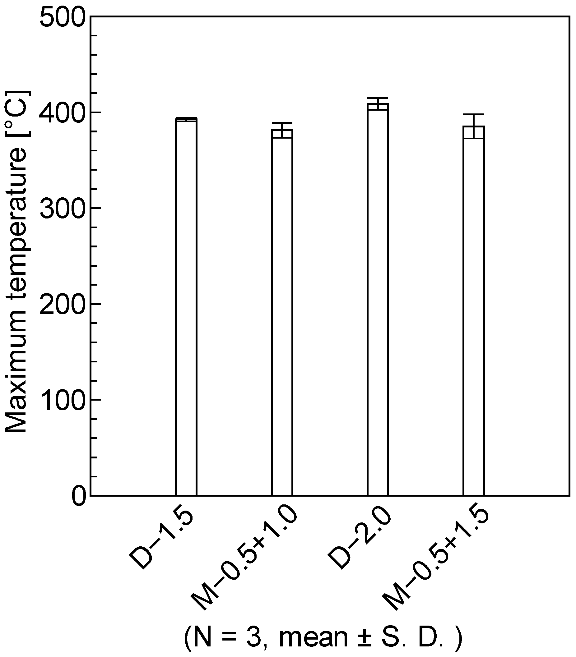
  • Compared to continuous heating, multi-stage heating can suppress excessive heating under the tool and reduce the temperature difference between the center and surrounding area, thereby moderating the temperature gradient formed during FSSW. For multi-stage heating, the pyrolysis area and maximum temperature were reduced by up to 37% and 6%, respectively, compared to continuous heating. Differences in temperature properties were caused by heat diffusion during the non-heating time and decreased frictional heat in the second stage.
  • The welded area for multi-stage heating joints increased by 27% compared to that for continuous heating joints. This difference is attributed to heat diffusion to the surrounding area during the non-heating time.
  • The use of multi-stage heating resulted in 210% longer fatigue life and up to 5% improvement in the tensile shear strength. The application of multi-stage heating increased tensile shear strength by suppressing void formation within the PA12 resin layer. Furthermore, the suppression of epoxy resin decomposition changed the crack propagation behavior and extended the fatigue life.

Author Contributions

Conceptualization, K.T.; data curation, Y.A.; funding acquisition, K.T.; investigation, Y.A.; methodology, K.T.; project administration, K.T.; resources, K.T.; supervision, K.T.; validation, K.T. and Y.A.; visualization, Y.A.; writing—original draft, Y.A.; writing—review and editing, K.T. All authors have read and agreed to the published version of the manuscript.

Funding

This research was partially supported by Individual Research Allowances, Doshisha University.

Data Availability Statement

Data are contained within this article.

Conflicts of Interest

The authors declare no conflicts of interest.

References

  1. Czerwinski, F. Current Trends in Automotive Lightweighting Strategies and Materials. Materials 2021, 14, 6631. [Google Scholar] [CrossRef] [PubMed]
  2. Wan, Y.; Takahashi, J. Development of Carbon Fiber-Reinforced Thermoplastics for Mass-Produced Automotive Applications in Japan. J. Compos. Sci. 2021, 5, 86. [Google Scholar] [CrossRef]
  3. Nagatsuka, K.; Xiao, B.; Wu, L.; Nakata, K.; Saeki, S.; Kitamoto, Y.; Iwamoto, Y. Dissimilar Materials Joining of Metal/carbon Fibre Reinforced Plastic by Resistance Spot Welding. Weld. Int. 2018, 32, 505–512. [Google Scholar] [CrossRef]
  4. Balle, F.; Wagner, G.; Eifler, D. Ultrasonic Metal Welding of Aluminium Sheets to Carbon Fibre Reinforced Thermoplastic Composites. Adv. Eng. Mater. 2009, 11, 35–39. [Google Scholar] [CrossRef]
  5. Yang, Y.; Liu, Z.; Wang, Y.; Li, Y. Numerical Study of Contact Behavior and Temperature Characterization in Ultrasonic Welding of CF/PA66. Polymers 2022, 14, 683. [Google Scholar] [CrossRef] [PubMed]
  6. Xia, H.; Ma, Y.; Chen, C.; Su, J.; Zhang, C.; Tan, C.; Li, L.; Geng, P.; Ma, N. Influence of Laser Welding Power on steel/CFRP Lap Joint Fracture Behaviors. Compos. Struct. 2022, 285, 115247. [Google Scholar] [CrossRef]
  7. Han, S.; Guang, X.; Li, Z.; Li, Y. Joining Processes of CFRP-Al Sheets in Automobile Lightweighting Technologies: A Review. Polym. Compos. 2022, 43, 8622–8633. [Google Scholar] [CrossRef]
  8. Mourad, A.H.I.; Harib, K.; El Domiaty, A. Fracture Behavior of Friction Stir Spot Welded Joint. ASME Press. Vessel. Pip. Div. 2010, 49255, 205–215. [Google Scholar] [CrossRef]
  9. RMishra, S.; Ma, Z.Y. Friction Stir Welding and Processing. Mater. Sci. Eng. R Rep. 2005, 50, 1–78. [Google Scholar] [CrossRef]
  10. Goushegir, S.M.; Scharnagl, N.; Santos, J.F.D.; Amancio-Filho, S.T. Durability of Metal-Composite Friction Spot Joints under Environmental Conditions. Materials 2020, 13, 1144. [Google Scholar] [CrossRef] [PubMed]
  11. Ogawa, Y.; Akebono, H.; Tanaka, K.; Sugeta, A. Effect of Welding Time on Fatigue Properties of Friction Stir Spot Welds of Al to Carbon Fibre-Reinforced Plastic. Sci. Technol. Weld. Join. 2019, 24, 235–242. [Google Scholar] [CrossRef]
  12. Geng, P.; Ma, N.; Ma, H.; Ma, Y.; Murakami, K.; Liu, H.; Aoki, Y.; Fujii, H. Flat Friction Spot Joining of Aluminum Alloy to Carbon Fiber Reinforced Polymer Sheets: Experiment and Simulation. J. Mater. Sci. Technol. 2022, 107, 266–289. [Google Scholar] [CrossRef]
  13. Goushegir, S.M.; Santos, J.F.D.; Amancio-Filho, S.T. Influence of Process Parameters on Mechanical Performance and Bonding Area of AA2024/carbon-Fiber-Reinforced Poly (phenylene Sulfide) Friction Spot Single Lap Joints. Mater. Des. 2015, 83, 431–442. [Google Scholar] [CrossRef]
  14. Tanaka, K.; Teramura, T.; Katayama, T.; Nishiguchi, K. Friction Stir Spot Welding of CFRP and Aluminum Alloy with Themoplastic Adhesive. In WIT Transactions on the Built Environment; WIT Press: Southampton, UK, 2016; Volume 166, pp. 391–401. ISBN 9781784661434. [Google Scholar]
  15. Tanaka, K.; Niwa, K.; Katayama, T.; Nishiguchi, K. Friction stir spot welding for CFRP/Al with polyamide resin. J. Soc. Mater. Sci. 2020, 69, 379–385. [Google Scholar] [CrossRef]
  16. Tanaka, K.; Kawakami, M.; Nishiguchi, K. Friction Stir Spot Welding for CFRP/Al Using Laminated Composites with an Outermost Layer of Thermoplastic Resin. J. Soc. Mater. Sci. 2022, 71, 453–460. [Google Scholar] [CrossRef]
  17. Japanese Industrial Standard(JIS) Z 3140:2017; Method of Inspection and Acceptance Levels for Resistance Spot Welds. Japanese Industrial Standards Committee: Tokyo, Japan, 2017.
  18. Schieler, O.; Beier, U. Induction Welding of Hybrid Thermoplastic-Thermoset Composite Parts. Appl. Sci. Eng. Prog. 2016, 9, 27–36. [Google Scholar] [CrossRef]
  19. Cai, B.P.; Liu, Y.H.; Ren, C.K.; Liu, Z.K.; Tian, X.J.; Abulimiti, A.B.B. Experimental Study of Galvanic Corrosion Behaviour of Carbon Fibre Composite Coupled to Aluminium in Artificial Seawater. Corros. Eng. Sci. Technol. 2012, 47, 289–296. [Google Scholar] [CrossRef]
  20. Zou, P.; Zhang, H.; Lei, M.; Cheng, D.; Huang, S.; Yang, F. Interfacial Microstructure and Formation of Direct Laser Welded CFRP/Ti-6Al-4V Joint. Metals 2021, 11, 1398. [Google Scholar] [CrossRef]
  21. Villegas, I.F.; Rubio, P.V. On Avoiding Thermal Degradation during Welding of High-Performance Thermoplastic Composites to Thermoset Composites. Compos. Part A Appl. Sci. Manuf. 2015, 77, 172–180. [Google Scholar] [CrossRef]
  22. Choi, J.-W.; Morisada, Y.; Liu, H.; Ushioda, K.; Fujii, H.; Nagatsuka, K.; Nakata, K. Dissimilar Friction Stir Welding of Pure Ti and Carbon Fibre Reinforced Plastic. Sci. Technol. Weld. Join. 2020, 25, 600–608. [Google Scholar] [CrossRef]
Figure 1. Schematic drawing of the laminated configuration of CFRPs.
Jcs 08 00110 g001
Figure 2. Molding temperature of CFRPs.
Jcs 08 00110 g002
Figure 3. Surface of Al: (a) untreated; (b) electropolished; (c) anodized.
Jcs 08 00110 g003
Figure 4. Schematic view of FSSW: (a) construction of load cell, motor, and tool; (b) fixing and welding of specimens.
Jcs 08 00110 g004
Figure 5. FSSW conditions: (a) D-1.5; (b) M-0.5 + 1.0; (c) D-2.0; (d) M-0.5 + 1.5.
Jcs 08 00110 g005
Figure 6. Schematic drawing of the cross-section of the joint. The arrow shows the observed direction.
Jcs 08 00110 g006
Figure 7. Schematic drawing of thermography observation.
Jcs 08 00110 g007
Figure 8. Schematic drawing of the fracture surface of the joint.
Jcs 08 00110 g008
Figure 9. TGA results of epoxy and PA12 resin.
Jcs 08 00110 g009
Figure 10. Temperature distribution images: (a) original observed view; (b) melted area (>179 °C); (c) decomposed area (>350 °C).
Jcs 08 00110 g010
Figure 11. History of load and maximum temperature of joints: (a) D-2.0; (b) M-0.5 + 1.5.
Jcs 08 00110 g011
Figure 12. Calculated melted/decomposed areas based on temperature distribution results.
Jcs 08 00110 g012
Figure 13. Maximum temperature of joints.
Jcs 08 00110 g013
Figure 14. Fracture load and welded areas of tensile shear tests.
Jcs 08 00110 g014
Figure 15. Joint strength of tensile shear tests.
Jcs 08 00110 g015
Figure 16. Fracture surfaces of tensile shear tests: (a) D-1.5; (b) M-0.5 + 1.0; (c) D-2.0; (d) M-0.5 + 1.5.
Jcs 08 00110 g016aJcs 08 00110 g016b
Figure 17. Fatigue life of fatigue tests.
Jcs 08 00110 g017
Figure 18. Fracture surfaces of fatigue tests: (a) D-2.0; (b) M-0.5 + 1.5.
Jcs 08 00110 g018
Figure 19. SEM images of joint cross-section: (a) D-2.0; (b) M-0.5 + 1.5. The void areas are surrounded by yellow lines.
Jcs 08 00110 g019
Figure 20. Estimated schematic drawing of fatigue crack propagation.
Jcs 08 00110 g020
Disclaimer/Publisher’s Note: The statements, opinions and data contained in all publications are solely those of the individual author(s) and contributor(s) and not of MDPI and/or the editor(s). MDPI and/or the editor(s) disclaim responsibility for any injury to people or property resulting from any ideas, methods, instructions or products referred to in the content.

