Article

Mechanical and Thermal Properties of Multilayer-Coated 3D-Printed Carbon Fiber Reinforced Nylon Composites

The Future Lab, Tsinghua University, Beijing 100084, China
*
Author to whom correspondence should be addressed.
J. Compos. Sci. 2023, 7(7), 297; https://doi.org/10.3390/jcs7070297
Submission received: 29 June 2023 / Revised: 11 July 2023 / Accepted: 18 July 2023 / Published: 20 July 2023
(This article belongs to the Special Issue Carbon Fiber Composites, Volume II)

Abstract

:
This paper evaluates the mechanical and thermal properties of 3D-printed short carbon fiber reinforced composites (sCFRPs). A numerical analysis was developed to predict the mechanical and thermal properties of the sCFRPs, which were verified via experimental tests. In the experiments, a novel technique was adopted by coating the sCFRPs with carbon fiber fabric and copper mesh to further improve its mechanical and thermal performance. Various copper meshes (60-mesh, 100-mesh and 150-mesh) were integrated with carbon fiber fabric to form a multilayer structure, which was then coated on the surface of Nylon 12-CF composite material (base material) to form a composite plate. The effects of the copper mesh on the mechanical and thermal properties of the composite plate were studied theoretically and experimentally. The results show that the addition of different copper meshes had a significant influence on the mechanical and thermal properties of the composite plate, which contained carbon fiber fabric, copper mesh and the base material. Among them, the mechanical and thermal properties of the composite plate with the 60-mesh copper mesh were significantly improved, while the improvement effect slowly declined with the increase in the thickness of the base material. The composite plate with 100-mesh and 150-mesh copper meshes had improved mechanical properties, whereas the influence on its thermal conductivity was limited. For thermal conductivity calculation, both the thickness and length directions of the heat transfer were considered. The comparative analysis indicated that the calculated values and experimental results are in excellent agreement, meaning that this numerical model is a useful tool for guiding the design of surface lamination for 3D-printed sCFRPs.

1. Introduction

Carbon fiber reinforced composites (CFRPs) have the advantages of light weight, high strength, fatigue resistance, corrosion resistance and excellent designability, and are widely used in aerospace, wind power, sports and leisure, the automotive industry and bridge construction [1,2,3,4,5,6,7]. With 3D printing technology, the advantages of material properties and the process characteristics of the rapid forming of complex structures can be brought into play simultaneously. This combined application breaks the limitations of traditional winding, laying, lamination and other manufacturing methods on the design of composite materials [8,9,10,11,12,13,14,15]. The 3D printing of short carbon fiber reinforced nylon composites (sCFRPs) has been adopted extensively, and their application in service robots can help lighten the weight of the robots in terms of the aspects of material and structure optimization [16,17,18,19]. However, moderate mechanical performance and poor thermal conductivity limit its application in key links with bearing capacity and heat conduction requirements [20]. Therefore, further optimization of the mechanical and thermal performance of the 3D-printed sCFRPs is mandatory to enrich its application in various fields.
Much research has been conducted in the selection of printed raw materials and interface modification, such as the modification of carbon fiber surfaces [21,22,23], the metallization treatment in the process of composite material molding [24] and the selection of continuous carbon fiber as the reinforcement phase and polyether ether ketone and other high-thermal-performance thermoplastic resins as the matrix [25]. Since composite materials exhibit different characteristics compared with metal materials, the traditional metal surface treatment process may not be suitable for composite materials [26]. Therefore, in order to improve the electrical and thermal conductivity of composite components, surface metallization treatment is adopted [27]. A very thin and dense metal coating is formed on the surface of a composite matrix via chemical plating, magnetron sputtering, arc ion plating and vacuum evaporation, and this coating plays a conductive and protective role. Nevertheless, further investigation is needed for complex structural components. Therefore, in the existing commercial use of 3D-printed short carbon fiber composites, it is still necessary to explore a surface-strengthening treatment method that is straightforward and suitable for complex parts.
Carbon fiber fabric is an excellent reinforcing material which has been widely used in the bridge, construction, hydropower and other industries [28,29,30]. By applying fiber fabric on the surface of the component for reinforcement, the mechanical properties of the component can be improved without increasing the weight and cross-section size of the structural component [31]. In addition, copper mesh has been used as an antistatic surface layer for CFRPs due to its excellent electrical and thermal conductivity and ductility [32,33,34]. This paper combines carbon fiber fabric and copper mesh to form a multilayer coating on the surface of a 3D-printed carbon fiber reinforced nylon composite component, and investigates the effects on the mechanical and thermal properties of the component.

2. Materials and Methods

2.1. Materials

The Nylon 12-CF composite filament was purchased from Stratasys with a short carbon fiber content of 35%. Carbon fiber fabric (T300-3K) was a twill fabric purchased from Toray Corporation of Japan (Tokyo, Japan). Copper meshes (60-mesh, 100-mesh and 150-mesh) were purchased from Churui Hardware Products Ltd. (Hengshui, China). The base adhesive (Yini special covering adhesive for carbon fiber) and surface adhesive (Yini epoxy resin adhesive) were purchased from Yini Composite Materials Ltd. (Dongguan, China). The vacuum bag used was PE/PA copolymer purchased from Tang Zheng Machinery Co., Ltd. (Suzhou, China).

2.2. Sample Preparation

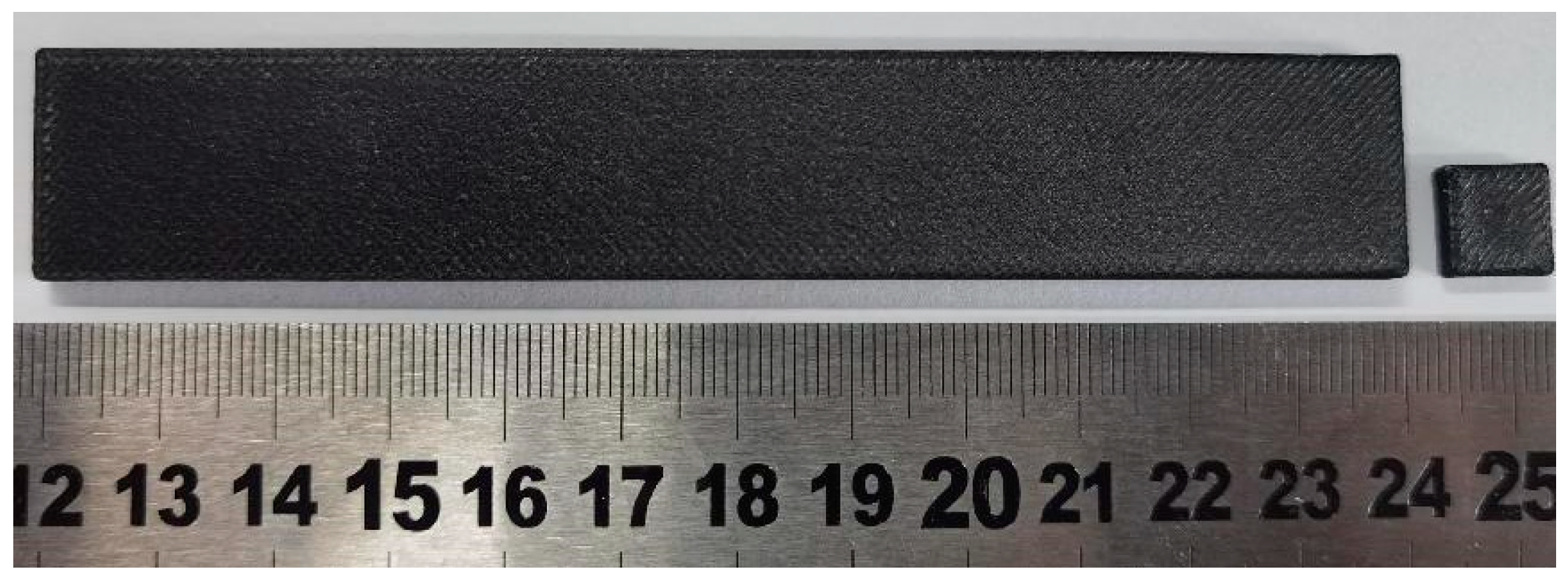
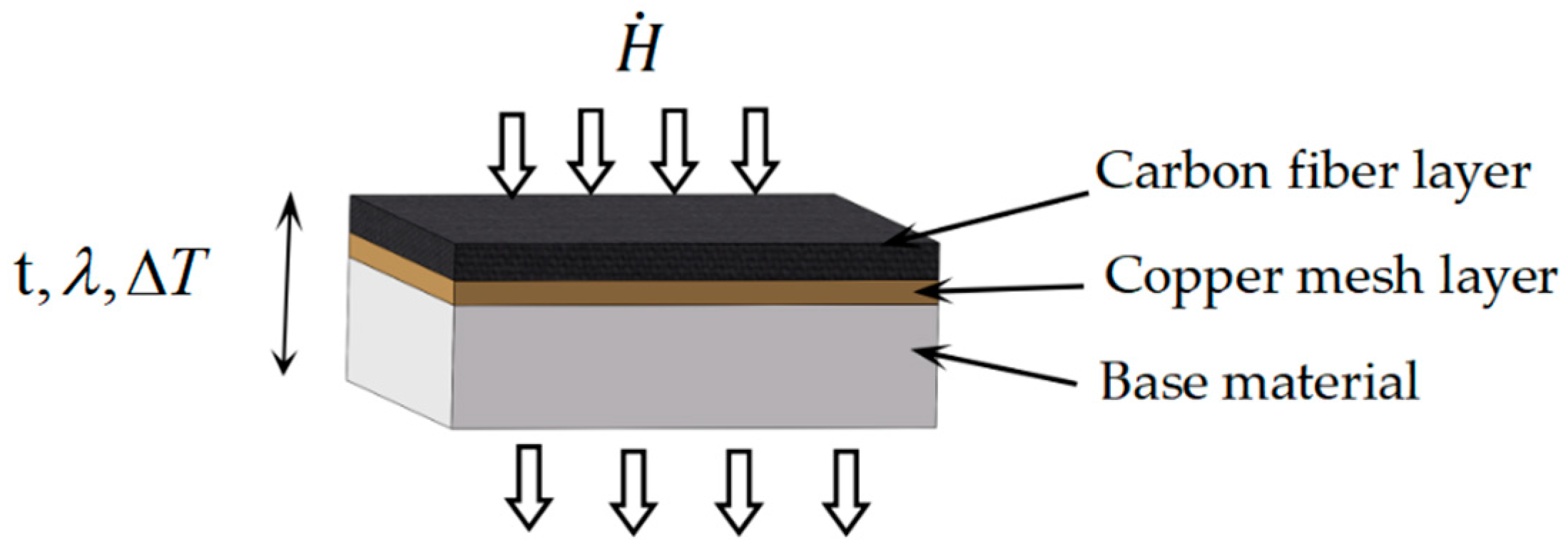
2.2.1. Preparation of the Base Material

Stratasys’ Fortus 380 mc Carbon Fiber FDM 3D printer was used to print the base material, with dimensions of 120 × 20 × 2.1 mm, 120 × 20 × 3.15 mm, 120 × 20 × 4.15 mm, 10 × 10 × 1 mm and 10 × 10 × 2 mm. An example of the specimens is shown in Figure 1. The 3D printing process parameters of the specimens are shown in Table 1.

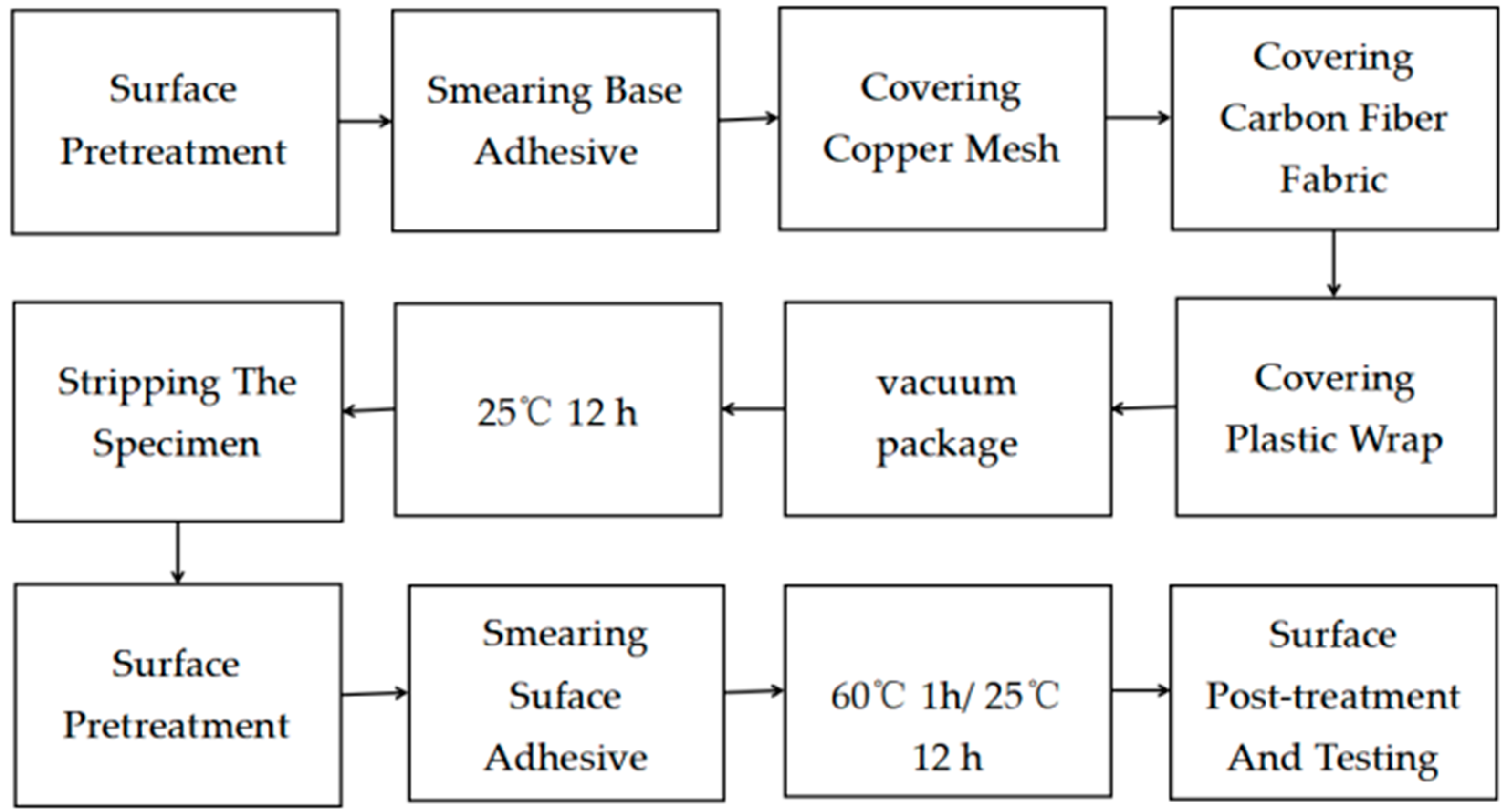
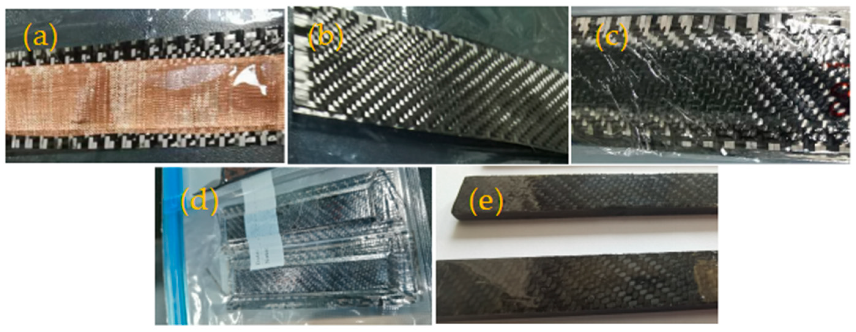
2.2.2. Coating Sample Preparation

The copper meshes, carbon fiber fabric and plastic film were first trimmed to a specified dimension (slightly larger than the base material). The surface of the base material was then polished with 180-mesh sandpaper and cleaned with alcohol. The two-part epoxy resin base adhesive was prepared according to the mass ratio of 1:1, and after slowly stirring evenly, the adhesive was evenly applied on the surface of the specimen with a nylon brush. The adhesive surface density was roughly 0.1 g/cm2. Then, the copper mesh and carbon fiber fabric were laid in turn, the whole sample was wrapped with polyethylene (PE) plastic film, and the sample was stored in vacuum bag at room temperature (not less than 25 °C). Once the base adhesive was completely cured, the specimen surface was then polished with 1500-mesh sandpaper, and cleaned with alcohol. The two-part epoxy resin surface adhesive was prepared according to the mass ratio of 1:2, and after stirring evenly, the adhesive was applied on the surface with a nylon brush, and the thickness of the adhesive layer was controlled at about 0.02–0.03 mm via the control of the adhesive amount applied. The sample was then transferred into an oven kept at 60 °C for 1 h, or at room temperature (not less than 25 °C) for 12 h. The adhesive was applied 3~4 times until the desired thickness was reached. The composite plates were cured and polished before the test. Both sides of the base material were coated for the bending test, while only one side of the base material was coated for the thermal conductivity test. The schematic diagram for the preparation of coated sCFRPs and the process illustration are shown in Figure 2 and Figure 3, respectively.
Four kinds of coated sCFRPs were prepared by using the base material with thicknesses of 2.1 mm, 3.15 mm and 4.15 mm: the surface only coated with carbon fiber fabric; the surface coated with 60-mesh copper mesh and carbon fiber fabric (#60); the surface coated with 100-mesh copper mesh and carbon fiber fabric (#100); and the surface coated with 150-mesh copper mesh and carbon fiber fabric (#150).

2.3. Sample Characterization

The sides of the #60, #100 and #150 composite plates were polished and cleaned with alcohol before being placed under a microscope (BX53M, Olympus, Toyko, Japan) to observe the microstructure of the sides of the coated sCFRPs.
Three-point bending properties of the base material (without coating) and four kinds of coated sCFRPs were tested using a mechanical testing machine (50ST, Tinius Olsen, Shanghai, China) according to the GB/T1449-2005 standard. The test span was 35 mm, and the loading speed was set at 1 mm/min. The bending modulus E was calculated using Equation (1).
E = L 3 × Δ P 4 bh 3 × Δ S
where E is the flexural elastic modulus, Pa; Δ P is the load increment in the initial straight section of the deflection curve, N; Δ S is the deflection increment at the midpoint of span corresponding to load increment Δ P , m; L is the span between two supports, m; and b and h are the width and thickness of the sample, respectively, m.
The thermal conductivity of the base material and four kinds of coated sCFRPs were tested using a laser thermal conductivity meter (LFA467, Netzsch, Selb; Germany). The test temperature was 70 °C, and the thermal conductivity was calculated using Equation (2).
λ = C p × D × ρ
where λ is the thermal conductivity, W/(m·K); C P is the specific heat capacity, J/(kg·K); D is the thermal diffusion coefficient, mm2/s; and ρ is the material density, kg/m3.

3. Results and Discussion

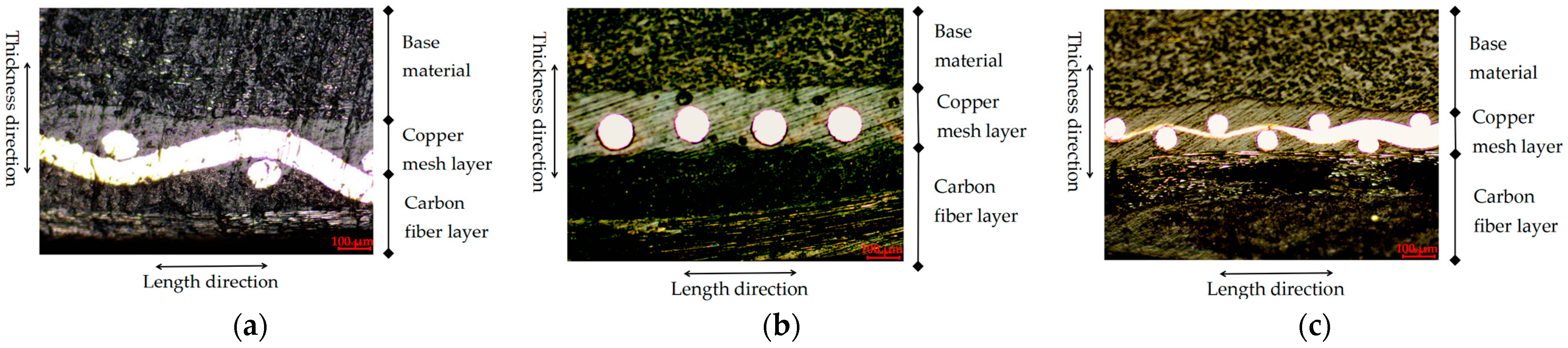
3.1. Microstructure Analysis

Figure 4 shows the microstructure of the coated sCFRPs with various copper meshes. As can be seen from Figure 4, the overall thickness is increased by about 0.5 mm, and the carbon fiber fabric forms a dense composite material with the base adhesive and the surface adhesive, which is recorded as the carbon fiber layer with a thickness of about 0.3 mm. The copper mesh and the base material form a dense composite material, which is referred to as the copper mesh layer with a thickness of about 0.2 mm.
At the interface between the carbon fiber layer and the copper mesh layer, it can be found that the carbon fiber fabric and copper mesh are interwoven together to form a composite skin containing carbon fiber fabric and copper mesh as the reinforcement phase and epoxy resin as the matrix. At the reinforcing phase, the volume fraction of the continuous copper wire in the copper mesh can affect the mechanical properties of the composite. The pore size of the copper mesh directly affects the structure of this composite material, which is because the pores of the slightly larger copper mesh can make more carbon fiber fabric interwoven in the larger copper mesh surface and pores, forming a composite material with a complex reinforced phase structure. On the interface between the copper mesh layer and the base material, the copper mesh layer and the base material are directly adhered together through the base adhesive.

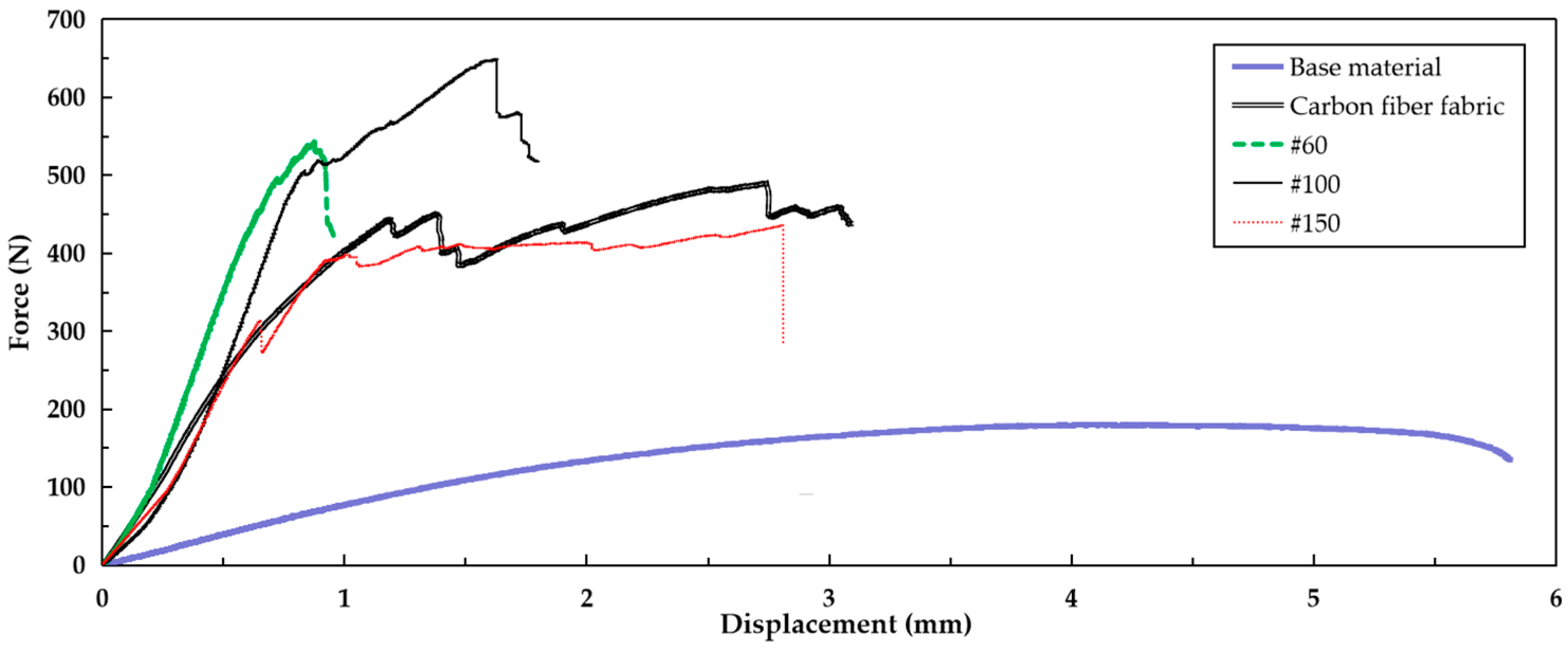
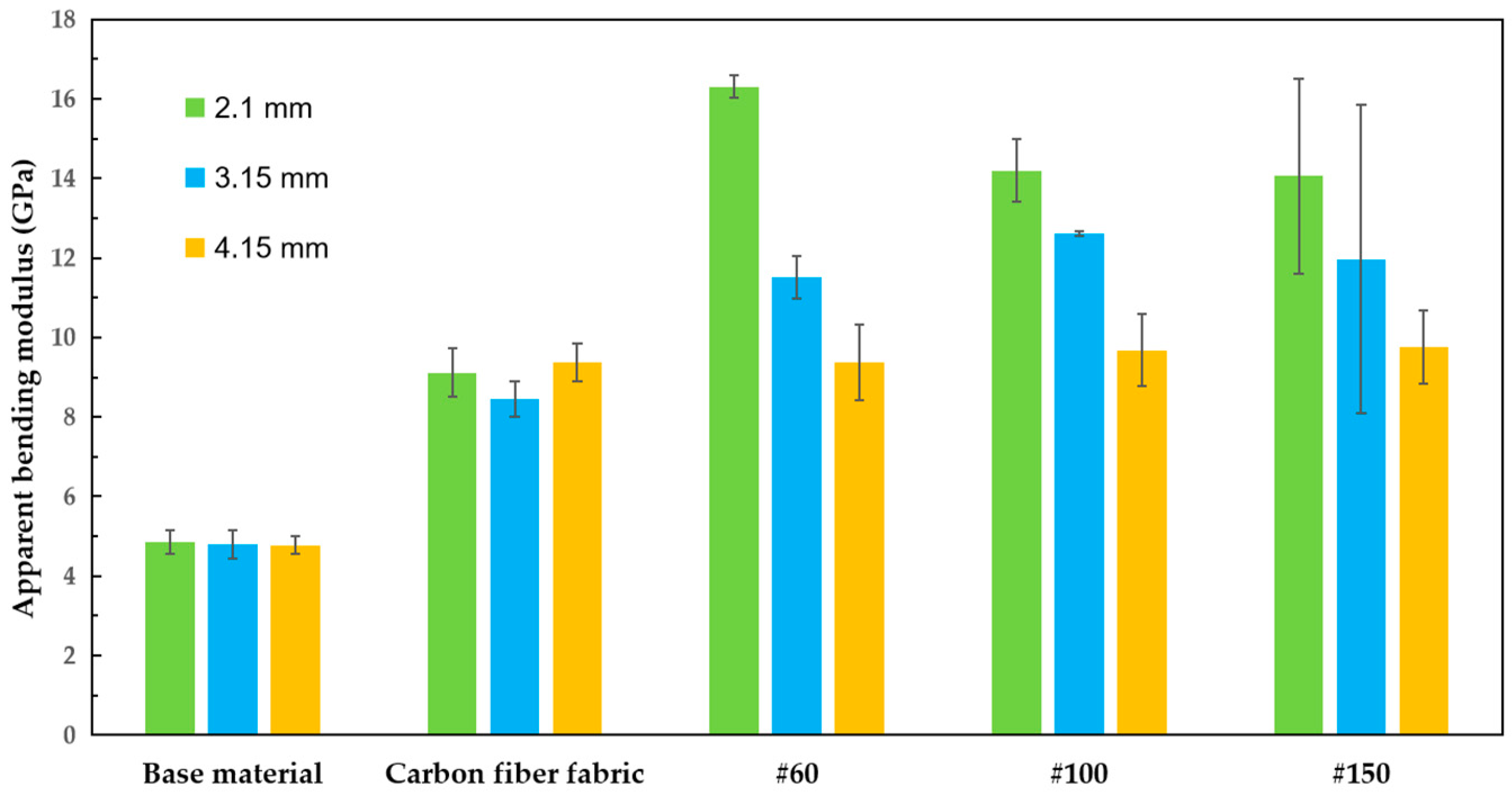
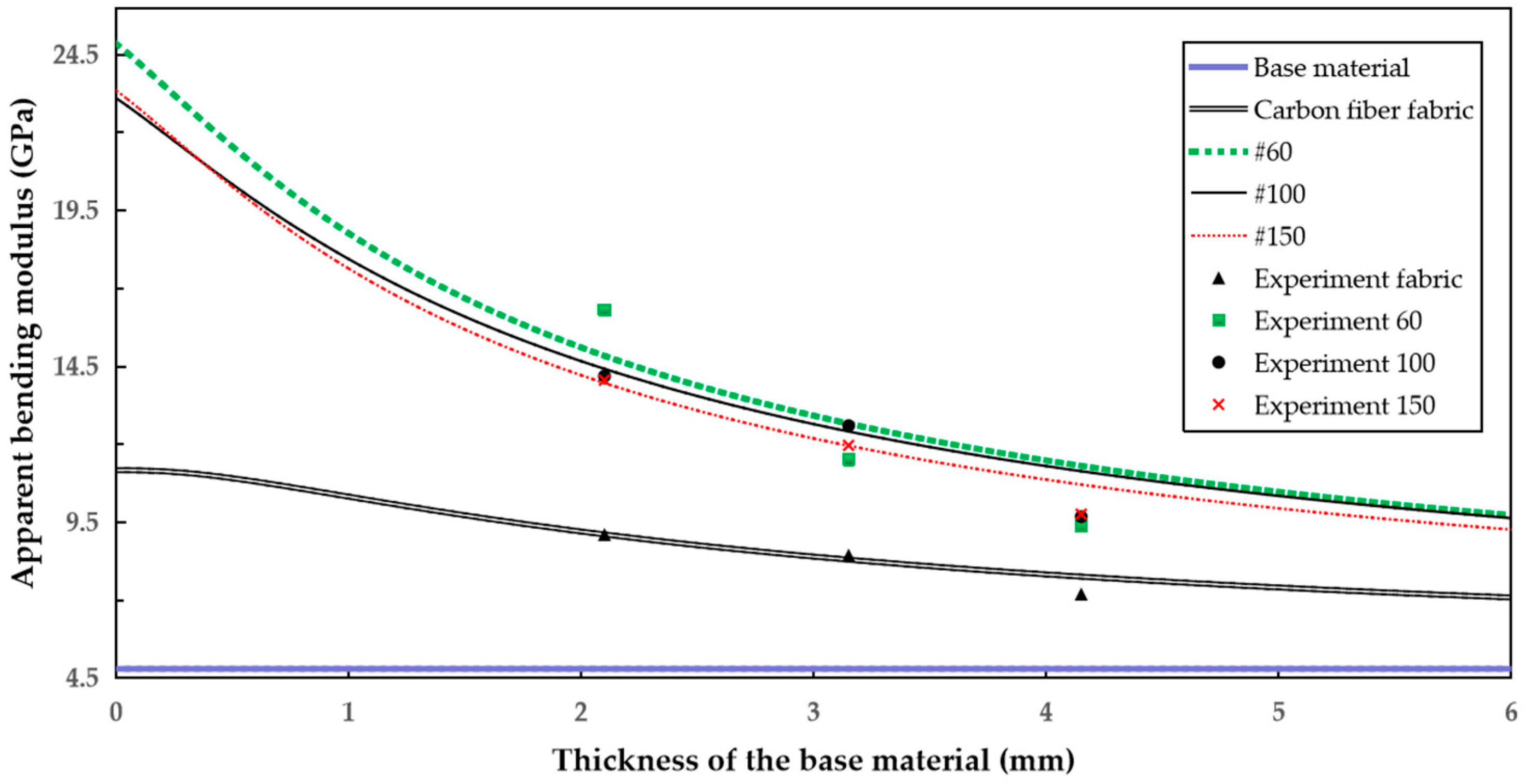
3.2. Bending Properties

In the bending process of the sample, the force–displacement curves are nonlinear, as shown in Figure 5. The coating film plays a major role in bearing the load, and the use of different copper meshes affects the bending performance of the sample. When the force is loaded to a certain extent, the curve first exhibits a slight fluctuation, which is a slight fold fracture of the carbon fiber layer on the extruded surface. With the increase in force, the carbon fiber layer and copper mesh layer on the stretched surface also gradually fold and fracture. When the maximum bending force is reached, the amplitude of the curve decreases rapidly, resulting in the obvious fracture of the carbon fiber layer and the copper mesh layer on the stretched surface, and at the same time, the debonding of the coating layer in the stressed area appears.
The maximum failure force of the specimen can be obtained through the bending test. The width and thickness of the sample measured before the test are substituted into Equation (1) to obtain the elastic modulus, and the calculated mean value of the three tests of each group of samples is taken. The mean value of the elastic modulus is shown in Figure 6. The results show that the bending property of carbon fiber fabric is greatly improved when the base material is coated with carbon fiber fabric. Moreover, with the addition of copper mesh, its bending property is further increased. When the thickness of the base material is 2.1 mm, the mean bending moduli of the #60, #100 and #150 composite plates are 16.31 GPa, 14.19 GPa and 14.06 GPa, respectively. The bending modulus of the #60 composite plate is the largest, as it is 240% and 79% higher than those of the base material and the sample coated with carbon fiber fabric only, respectively. Generally, the experiment results exhibit good repeatability, except for the #150 composite plate; its error is slightly larger. This may be because the pores of the 150-mesh copper mesh are very small, which is not conducive to the penetration of the base adhesive; the composite of the copper mesh layer and the carbon fiber layer is incomplete; the area of the copper mesh layer adhering to the base material is much smaller; and more of the base adhesive is retained on the surface of the base material, resulting in the thickness of the sample becoming much larger, and these factors cause instability in the performance of the sample. When the thickness of the base material is increased, the bending modulus of the coated sCFRPs decreases slightly.

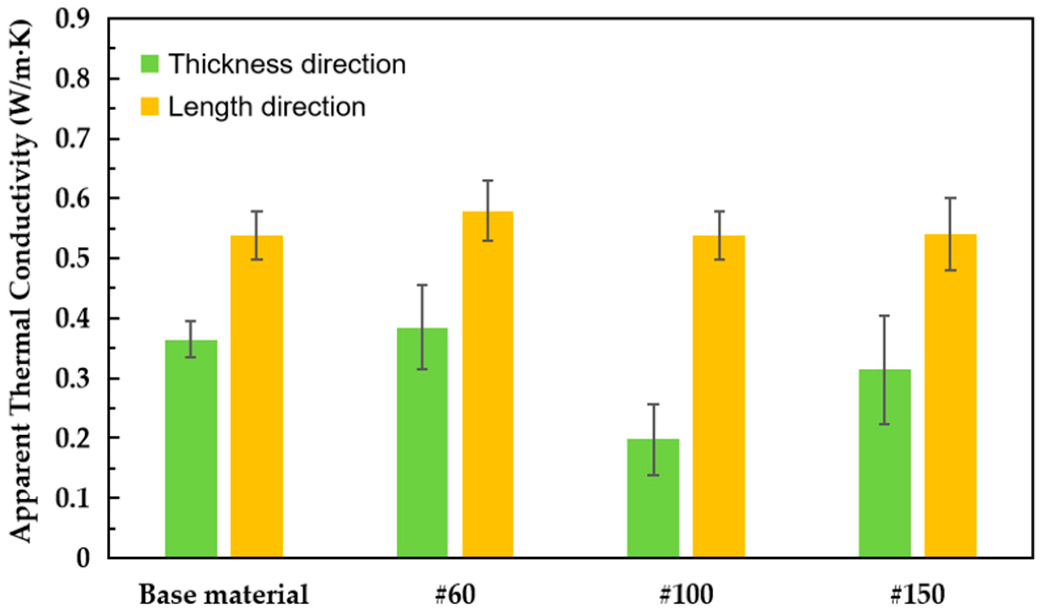
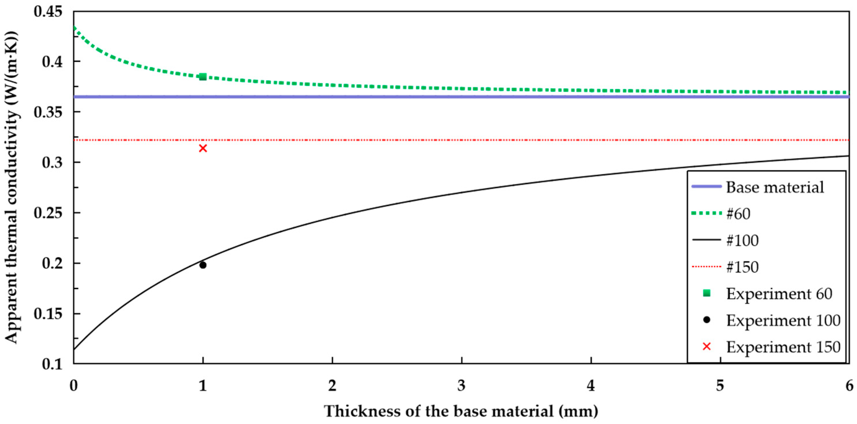
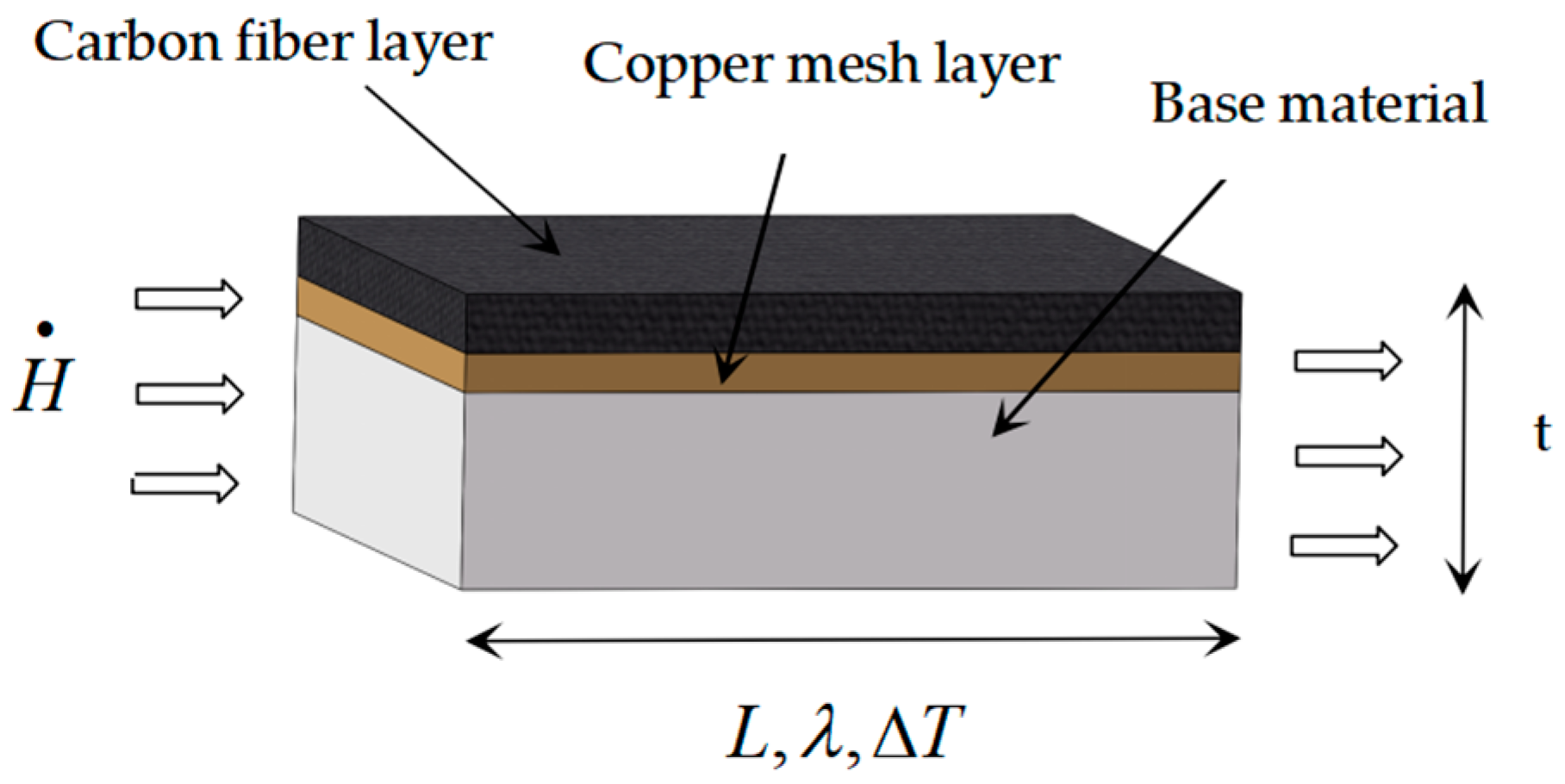
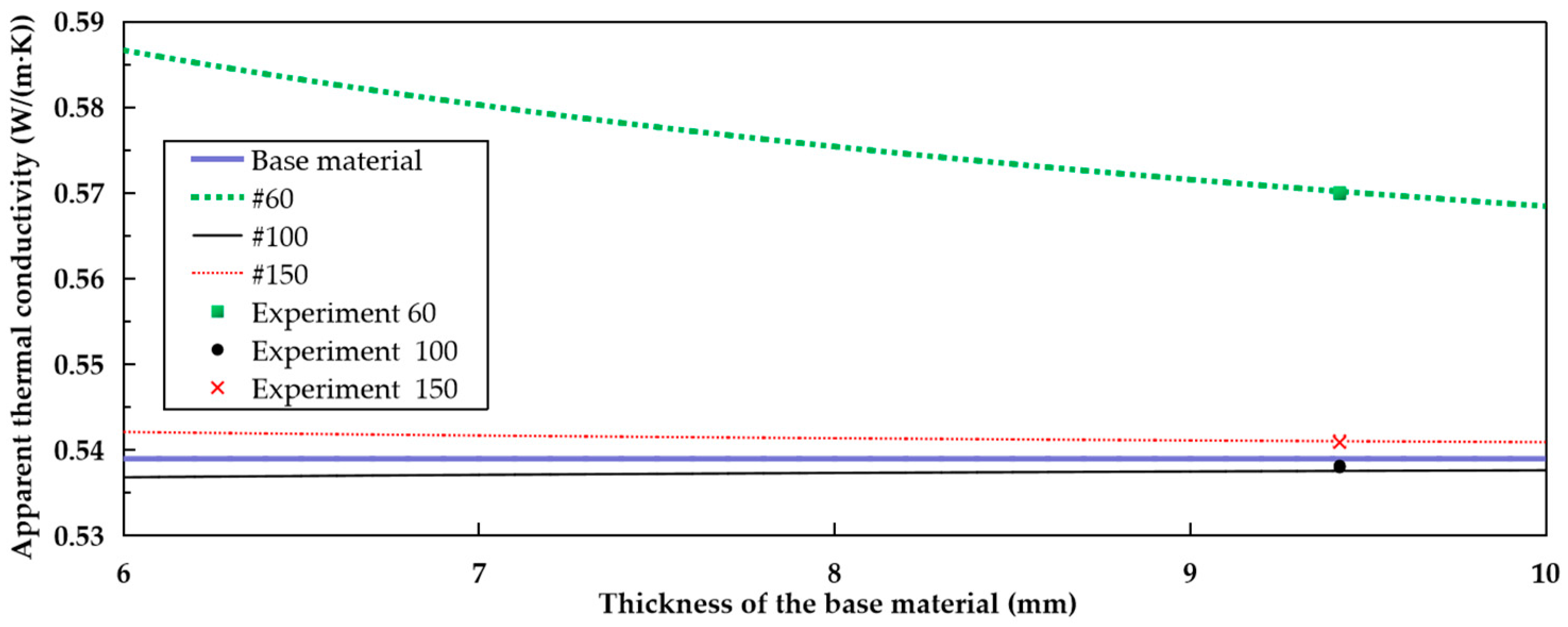
3.3. Thermal Conductivity
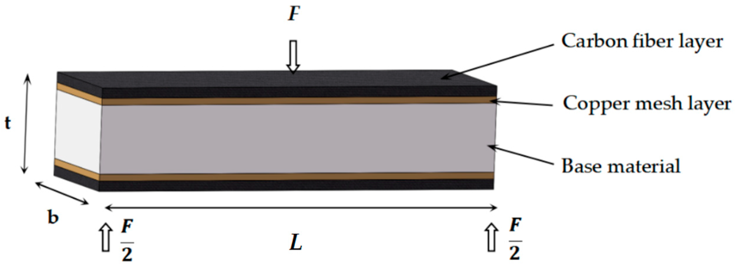
Figure 7 shows the influence of the addition of different copper meshes on the thermal conductivity of the coated sCFRPs in terms of thickness direction and length direction. The results indicate that only the thermal conductivity of the #60 composite plate is slightly improved. This may be because the pores of the copper mesh in #60 are slightly larger, which can make more carbon fiber fabric interweave with the copper mesh, forming a large area of a continuous heat transfer interface, resulting in higher thermal conductivity.
The thermal conductivity of the specimens in the thickness direction was also examined. The thickness of the base material was 1 mm, and the thermal conductivity of the #60 composite plate was increased by 5.5% compared with that of the base material. To test the thermal conductivity in the direction of length, the thickness of the base material is 9.42 mm, and the thermal conductivity of the #60 composite plate is increased by 7.4% compared with that of the base material.

4. Numerical Model

In order to predict the influence of copper mesh on the mechanical properties and thermal conductivity of composite plates with different thicknesses of base material, the appropriate thicknesses of the base material and copper mesh can be selected for multilayer surface coating to improve the mechanical properties and thermal conductivity of composite plates. For simplicity, several assumptions were made in this model. It was assumed that the interface between the copper mesh layer and the base material does not separate, and the heat loss in the interface is negligible. The composite plate can be simplified into a sandwich structure formed by the base material, the copper mesh layer and the carbon fiber layer; in addition, the interface between the layers is a plane.

4.1. Calculation of Bending Properties

By using Equations (3)–(5), the relationship between the bending modulus of the coated sCFRP and the thickness of the base material can be calculated, as shown in Figure 8
I = bt 3 12
E I = E 1 I 1 + E 2 I 2 + E 3 I 3
E = E 1 t 1 3 + E 2 [ ( t 1 + 2 t 2 ) 3 t 1 ] 3 + E 3 [ ( t 1 + 2 t 2 + 2 t 3 ) 3 ( t 1 + 2 t 2 ) 3 ] t 1 + 2 t 2 + 2 t 3
where I , I 1 , I 2 , I 3 are the moments of inertia of the composite plate, base material, copper mesh layer and carbon fiber layer, respectively, m 4 ; E , E 1 , E 2 , E 3 are the bending moduli of the composite plate, base material, copper mesh layer and carbon fiber layer, respectively, Pa; t , t 1 , t 2 , t 3 are the thicknesses of the composite plate, base material, copper mesh layer and carbon fiber layer, respectively, m; L is the distance between the two supports, m; and b is the width of the composite plate, m.
The experimental values of the specimens with three thicknesses of base material were substituted into Equation (5) to calculate E 1 and E 2 , and their average values were taken into Equation (5) to depict the relationship, as shown in Figure 9 and Table A1.
The bending modulus comparison between the calculated and experimental results. The bending modulus tends to decrease with the increase in the thickness of the base material. When the thickness of the base material is 2.1 mm, the #60 composite plate shows the highest modulus. As the thickness of the base material increases, the changes in the bending properties of the coated sCFRPs are negligible.
It is worth mentioning that the largest discrepancy between the calculated data of the #60, #100 and #150 composite plates and the test values is within 10%. When the thickness of the base material is small, the error between the simulated data and the test values is less than 10%, and the data are in good agreement. This can be used as a reference guide for actual production. However, when the thickness of the base material increases, the numerical model overestimates the bending modulus, and this is because the phenomenon of uneven film coating stripping occurs during bending, thus reducing the effect of the coating on the bending performance of the composite plate.

4.2. Calculation of Thermal Conductivity

In this calculation, it is assumed that each layer maintains a continuous form of aggregation to form a continuous block, and the heat flow is conducted in series or parallel mode [35].

4.2.1. Thickness Direction (Series Mode)

According to the series heat transfer, the heat flow through each layer is assumed to be constant, and the temperature difference between the top and bottom ends of the composite plate is equal to the sum of the temperature differences of each layer, as shown in Figure 10. Equation (8) can be derived using Equations (6) and (7). The relationship between the thermal conductivity of the composite plate along the thickness direction and the thickness of the matrix is calculated as shown in Figure 11 and Table A2.
H = λ Δ T t = λ 1 Δ T 1 t 1 = λ 2 Δ T 2 t 2 = λ 3 Δ T 3 t 3
Δ T = Δ T 1 + Δ T 2 + Δ T 3
λ = t 1 λ 1 + t 2 λ 2 + t 3 λ 3 t 1 + t 2 + t 3
where H is the load-rated heat flow, W; Δ T , Δ T 1 , Δ T 2 , Δ T 3 are the temperature differences between the beginning and end of the composite plate, base material, copper mesh layer and carbon fiber layer in the thickness direction, respectively, °C; λ , λ 1 , λ 2 , λ 3 are the thermal conductivities of the composite plate, base material, copper mesh layer and carbon fiber layer in the thickness direction, respectively, W/(m·K); and t , t 1 , t 2 , t 3 are the thicknesses of the composite plate, base material, copper mesh layer and carbon fiber layer, respectively, m.
Only the thermal conductivity of the #60 composite plate is slightly improved, and the improvement effect is negligible as the thickness of the base material increases. It is worth mentioning that the calculated values and experimental results are in excellent agreement, meaning that this numerical model is a useful tool for guiding the structure design of coated sCFRPs.

4.2.2. Length Direction (Parallel Mode)

According to the parallel heat transfer, theoretically, the total heat flow is equal to the sum of the heat flows of each layer, and the temperature difference between the beginning and the end of each layer is the same, as shown in Figure 12. Equation (11) can be derived by using Equations (9) and (10). The relationship between the thermal conductivity of the composite plate and the thickness of the base material at 70 °C is calculated as shown in Figure 13 and Table A2.
H = λ t Δ T L = λ 1 t 1 Δ T 1 L + λ 2 t 2 Δ T 2 L + λ 3 t 3 Δ T 3 L
Δ T = Δ T 1 = Δ T 2 = Δ T 3
λ = λ 1 t 1 + λ 2 t 2 + λ 3 t 3 t 1 + t 2 + t 3
where H is the load-rated heat flow, W; L is the length of the composite plate; Δ T , Δ T 1 , Δ T 2 , Δ T 3 are the temperature differences between the left and right ends of the composite plate, base material, copper mesh layer and carbon fiber layer in the length direction, respectively, m; λ , λ 1 , λ 2 , λ 3 are the thermal conductivities of the composite plate, base material, copper mesh layer and carbon fiber layer in the length direction, respectively, W/(m·K); and t , t 1 , t 2 , t 3 are the thicknesses of the composite plate, base material, copper mesh layer and carbon fiber layer, respectively, m.
Only the thermal conductivity of the #60 composite plate is significantly improved, and this improvement slowly decreases as the thickness of the base material increases. When the thickness of the base material is 1–10 mm, the thermal conductivity of the #60 composite plate can be increased by 5–38% compared with that of the base material. It is worth mentioning that the calculated values and experimental results are in excellent agreement, meaning that this numerical model is a useful tool for guiding the design of coated sCFRPs.

5. Conclusions

The mechanical and thermal properties of a coated carbon fiber reinforced composite were investigated using experimental measurement and numerical analysis. The effects of various copper meshes and thicknesses of the base material on the performance were discussed. The results show that the addition of different copper meshes had a significant influence on the mechanical and thermal properties of the composite plate, which contained carbon fiber fabric, copper mesh and the base material. This is because of the differences in the diameter and porosity of the copper mesh; the coated sCFRPs is mixed to different degrees at the interface. It is the existence of this composite material that directly affects the mechanical and thermal properties of the composite plate. The adhesive layer of the base adhesive on the base material directly affects the mechanical properties of the composite plate.
Among the plates, the mechanical and thermal properties of the composite plate with a 60-mesh copper mesh were significantly improved, while the improvement slowly declined with the increase in the thickness of the base material. The composite plate with 100-mesh and 150-mesh copper meshes had improved mechanical properties, whereas the influence on thermal conductivity was limited. For a thermal conductivity calculation, both the thickness and length directions of the heat transfer were considered. The comparative analysis indicated that the calculated values and experimental results are in excellent agreement, meaning that this numerical model is a useful tool for guiding the structure design of coated sCFRPs.

Author Contributions

Investigation, data curation, visualization, validation, formal analysis and writing—original draft preparation, H.C.; writing—review and editing, K.W. and Y.C.; conceptualization, methodology and writing—review and editing, H.L. All authors have read and agreed to the published version of the manuscript.

Funding

This research was funded by Tsinghua University-Foshan Advanced Manufacturing Research Institute and Foshan Longshen Robot Company through a joint research grant (2020THFS0307) and the Ministry of Science and Technology of China through a special grant (G2021102010L).

Institutional Review Board Statement

Not applicable.

Informed Consent Statement

Not applicable.

Data Availability Statement

Not applicable.

Acknowledgments

The financial support of Tsinghua University-Foshan Advanced Manufacturing Research Institute and Foshan Longshen Robot Company is acknowledged. The authors are grateful for the support of colleagues at the Future Materials & Design Research Center, The Future Lab, Tsinghua University. The assistance of the technical staff at the Micro-Nano Heat Transfer Laboratory of the School of Aeronautics, Tsinghua University, is also acknowledged.

Conflicts of Interest

The authors declare no conflict of interest.

Appendix A

Table A1. Apparent bending modulus (GPa) of the samples.
Thickness of the base material (mm)Base MaterialCarbon Fiber Fabric#60#100#150
2.14.85 ± 0.299.11 ± 0.6116.31 ± 0.2914.19 ± 0.7914.06 ± 2.45
3.154.80 ± 0.358.45 ± 0.4511.51 ± 0.5412.6 ± 0.0611.97 ± 3.87
4.154.78 ± 0.239.37 ± 0.489.37 ± 0.959.68 ± 0.919.76 ± 0.92
Table A2. Thermal conductivities of the sample.
Apparent Thermal Conductivity (W/m·K)Base Material#60#100#150
Thickness direction0.365 ± 0.030.385 ± 0.070.338 ± 0.060.314 ± 0.09
Length direction0.539 ± 0.040.579 ± 0.050.198 ± 0.040.541 ± 0.06

References

  1. Fan, X. Application status and development trend of carbon fiber composites. Chem. Ind. 2019, 37, 12–16+25. [Google Scholar]
  2. Zheng, X.B. Research on the application of carbon fiber composites in aircraft structures. China Plant Eng. 2023, 521, 92–94. [Google Scholar]
  3. Mou, S.X.; Chen, C.; Qiu, G.J.; Jia, Z.Y. Application of carbon fiber composite materials in wind power blades. Adv. Mater. Ind. 2012, 219, 25–29. [Google Scholar]
  4. Duan, W.; Kong, X.X. Progress in the application of carbon fiber composites in the field of automotive lightweight. Automob. Parts 2023, 178, 84–87. [Google Scholar]
  5. Chen, W.; Bai, Y.; Zhu, J.Q.; Meng, L.H. Application of carbon fiber composite material in sports equipment. Tech. Text. 2011, 29, 35–37+43. [Google Scholar]
  6. Pang, S.X. Application of carbon fiber composite materials in water conservancy and hydropower reinforcement engineering. Synth. Mater. Aging Appl. 2023, 52, 120–122. [Google Scholar]
  7. Zheng, H.; Zhang, W.J.; Li, B.; Zhu, J.J.; Wang, C.H.; Song, G.J.; Ma, L.C. Recent advances of interphases in carbon fiber-reinforced polymer composites: A review. Compos. Part B Eng. 2022, 233, 109639. [Google Scholar] [CrossRef]
  8. Ning, F.D.; Cong, W.L.; Qiu, J.J.; Wang, S.R. Additive manufacturing of carbon fiber reinforced thermoplastic composites using fused deposition modeling. Compos. Part B 2015, 80, 369–378. [Google Scholar] [CrossRef]
  9. Zhang, H.Q.; Zhang, K.; Aonan, L.; Wan, L.; Robert, C.; Brádaigh, C.M.Ó.; Yang, D.M. 3D printing of continuous carbon fibre reinforced powder-based epoxy composites. Compos. Commun. 2022, 33, 101239. [Google Scholar] [CrossRef]
  10. Wang, C.L. Development and Application of Carbon Fiber Composites for 3D Printing. Master’s Thesis, General Research Institute of Mechanical Sciences, Beijing, China, 2012. [Google Scholar]
  11. Chen, X.M.; Yao, L.J.; Guo, L.C.; Sun, Y. A review of the research status of 3D printing continuous fiber reinforced composites. Hangkong Xuebao 2021, 42, 174–198. [Google Scholar]
  12. Blok, L.G.; Longana, M.L.; Yu, H.; Woods, B.K.S. An investigation into 3D printing of fibre reinforced thermoplastic composites. Addit. Manuf. 2018, 04, 039. [Google Scholar] [CrossRef]
  13. Yavas, D.Z.; Zhang, Z.Y.; Liu, Q.Y.; Wu, D.Z. Fracture Behavior of 3D Printed Carbon Fiber-Reinforced Polymer Composites. Compos. Sci. Technol. 2021, 208, 108741. [Google Scholar] [CrossRef]
  14. Masahito, U.; Shun, K.; Masao, Y.; Antoine, L.D. 3D compaction printing of a continuous carbon fiber reinforced thermoplastic. Compos. Part A 2020, 139, 105985. [Google Scholar]
  15. Song, X.D.; Pang, L.S. Research progress of carbon fiber resin matrix composites and their forming technology and application. Packag. Eng. 2021, 42, 81–91. [Google Scholar]
  16. Dang, L.; Zhang, M.Y.; Cheng, Y.N.; Yan, C. Application and development of 3D printing technology in composite materials. Technol. Innov. Appl. 2022, 12, 166–169. [Google Scholar]
  17. Yu, C.T.; Zhang, J.Y.; Wu, Y.B. Research progress in the application of lightweight materials for robots. Adv. Mater. Ind. 2019, 313, 41–45. [Google Scholar]
  18. Chen, H.W.; Liu, G.; Wang, X.W.; Le, H.R. Application and prospect of lightweight composite materials and 3D printing technology in service robots. J. Eng. Stud. 2022, 14, 30–39. [Google Scholar] [CrossRef]
  19. Li, D.D.; Shi, X.M.; Deng, S.P.; Qi, Y.M.; Chen, W.; Zhou, Y.Y.; Zhou, W.F. A review of the technology and development trend of collaborative robot industry. Equip. Manuf. Technol. 2021, 320, 73–76. [Google Scholar] [CrossRef]
  20. Research Progress in 3D Printing of Fiber-Reinforced Thermoplastic Composites. Available online: http://kns.cnki.net/kcms/detail/10.1683.TU.20230425.1709.002.html (accessed on 25 May 2023).
  21. Xu, Y.; Chi, Y.B. Effect of surface modification methods of carbon fiber on properties of reinforced nylon composites. China Sci. Technol. Inf. 2015, 511, 15–16. [Google Scholar]
  22. Zhang, D.D.; Zhang, F.H.; Yang, J.X.; Li, X.F.; Li, Y.X.; Zeng, Y. Progress in surface modification of carbon fiber and its application in nylon composites. Eng. Plast. Appl. 2019, 47, 141–146. [Google Scholar]
  23. Chu, C.X. Surface Modification of Carbon Fiber and Properties of Resin Matrix Composites. Master’s Thesis, Jinan University, Jinan, China, 2020. [Google Scholar]
  24. Wu, S.H. Study on Surface Metallization and Membrane Base Interface of Resin Matrix Composites. Master’s Thesis, Lanzhou University, Lanzhou, China, 2013. [Google Scholar]
  25. 3D Printing Continuous Carbon Fiber/Polyether Ketone Ketone Composite Process and Its Performance Control. Available online: https://doi.org/10.13801/j.cnki.fhclxb.20221215.002 (accessed on 26 May 2023).
  26. Liu, Y.F. Surface treatment methods for mechanical engineering materials. Coal Technol. 2008, 170, 22–24. [Google Scholar]
  27. Dong, X.Y.; Guo, J.H. Progress in surface metallization of fiber reinforced resin matrix composites. Compos. Sci. Eng. 2017, 277, 93–99. [Google Scholar]
  28. Li, H.H.; Chen, H.X.; Deng, C.L. Engineering practice of repairing underwater cracks in concrete piles with carbon fiber. Build. Struct. 2021, 51, 2119–2121. [Google Scholar]
  29. Wang, P.; Wang, X.; Hu, J.Y. Application of high strength carbon fiber fabric in the reinforcement technology of pressure steel pipe in hydropower plant. Appl. IC 2023, 40, 38–43. [Google Scholar]
  30. Huang, Q.G.; Huang, Z.; Jiang, J.; Xue, X.D. Performances of Carbon Fiber Cloth Reinforced Bamboos. Appl. Mech. Mater. 2012, 1801, 174–177. [Google Scholar]
  31. Al-Mahfooz, M.J.; Mahdi, E. Bending behavior of glass fiber reinforced composite overwrapping pvc plastic pipes. Compos. Struct. 2020, 251, 112656. [Google Scholar] [CrossRef]
  32. Xiao, Y.; Li, S.L.; Yin, J.J.; Yao, X.L.; Zhang, X.H. Experimental study on direct effect of lightning current on copper mesh composites. J. Aeronaut. Mater. 2018, 04, 109–114. [Google Scholar]
  33. Tian, M.H.; Liu, X.Y.; Wu, T.; Shan, Z.Z.; Lu, X. Analysis of the influence of the protective layer structure of copper mesh on the ablation damage of composite laminates by lightning strike. Sci. Technol. Eng. 2022, 21, 9071–9080. [Google Scholar]
  34. Lu, W.B. Preparation and Properties of Layered Pantograph Slide Plate. Ph.D. Thesis, Shandong University, Jinan, China, 2012. [Google Scholar]
  35. Li, P.M. Preparation and Properties of Epoxy Resin Based Thermal Conductivity Composites. Master’s Thesis, University of Electronic Science and Technology of China, Chengdu, China, 2012. [Google Scholar]
Figure 1. An example of the specimens.
Jcs 07 00297 g001
Figure 2. Schematic diagram for the preparation of coated sCFRPs.
Jcs 07 00297 g002
Figure 3. Preparation of coated sCFRPs: (a) copper mesh laid flat, (b) carbon fiber fabric laid flat, (c) wrapped in plastic film, (d) stored in a vacuum bag at room temperature, and (e) final specimen.
Jcs 07 00297 g003
Figure 4. The microstructures of the coated sCFRPs: (a) #60 composite plate, (b) #100 composite plate, (c) #150 composite plate.
Jcs 07 00297 g004
Figure 5. The force–displacement curves of the specimens.
Jcs 07 00297 g005
Figure 6. The comparison of bending moduli of the prepared specimens.
Jcs 07 00297 g006
Figure 7. Thermal conductivities of base material and coated sCFRPs.
Jcs 07 00297 g007
Figure 8. Three-point bending diagram of the composite plate.
Jcs 07 00297 g008
Figure 9. Bending modulus comparison between the calculated and experimental results.
Jcs 07 00297 g009
Figure 10. Schematic diagram of heat conduction in series mode.
Jcs 07 00297 g010
Figure 11. Thermal conductivity comparison between the calculated and experimental results in series mode.
Jcs 07 00297 g011
Figure 12. Schematic diagram of heat conduction in parallel mode.
Jcs 07 00297 g012
Figure 13. Thermal conductivity comparison between the calculated and experimental results in parallel mode.
Jcs 07 00297 g013
Table 1. The 3D printing process parameters.
Process ParameterPaving Direction (°)Nozzle Diameter (mm)Height (mm)Fill Line Width (mm)Fill Overlap (mm)Nozzle Temperature (°C)Print Speed (mm/s)Filling Rate (%)
Value±450.50.2540.430.01355-100
Disclaimer/Publisher’s Note: The statements, opinions and data contained in all publications are solely those of the individual author(s) and contributor(s) and not of MDPI and/or the editor(s). MDPI and/or the editor(s) disclaim responsibility for any injury to people or property resulting from any ideas, methods, instructions or products referred to in the content.

