Review

There Are over 60 Ways to Produce Biocompatible Calcium Orthophosphate (CaPO4) Deposits on Various Substrates

by
Sergey V. Dorozhkin
Faculty of Physics, M.V. Lomonosov Moscow State University, Leninskie Gory 1-2, Moscow 119991, Russia
J. Compos. Sci. 2023, 7(7), 273; https://doi.org/10.3390/jcs7070273
Submission received: 5 June 2023 / Accepted: 28 June 2023 / Published: 1 July 2023
(This article belongs to the Section Biocomposites)

Abstract

:
A The present overview describes various production techniques for biocompatible calcium orthophosphate (abbreviated as CaPO4) deposits (coatings, films and layers) on the surfaces of various types of substrates to impart the biocompatible properties for artificial bone grafts. Since, after being implanted, the grafts always interact with the surrounding biological tissues at the interfaces, their surface properties are considered critical to clinical success. Due to the limited number of materials that can be tolerated in vivo, a new specialty of surface engineering has been developed to desirably modify any unacceptable material surface characteristics while maintaining the useful bulk performance. In 1975, the development of this approach led to the emergence of a special class of artificial bone grafts, in which various mechanically stable (and thus suitable for load-bearing applications) implantable biomaterials and artificial devices were coated with CaPO4. Since then, more than 7500 papers have been published on this subject and more than 500 new publications are added annually. In this review, a comprehensive analysis of the available literature has been performed with the main goal of finding as many deposition techniques as possible and more than 60 methods (double that if all known modifications are counted) for producing CaPO4 deposits on various substrates have been systematically described. Thus, besides the introduction, general knowledge and terminology, this review consists of two unequal parts. The first (bigger) part is a comprehensive summary of the known CaPO4 deposition techniques both currently used and discontinued/underdeveloped ones with brief descriptions of their major physical and chemical principles coupled with the key process parameters (when possible) to inform readers of their existence and remind them of the unused ones. The second (smaller) part includes fleeting essays on the most important properties and current biomedical applications of the CaPO4 deposits with an indication of possible future developments.

1. Introduction

All known materials have their own specific properties and, depending on the applications, those properties may or may not be desirable. That is, certain ones are aggressive, corrosive or biotoxic; others are sensitive to light, heat and oxidation; some are hydrophilic, transparent, slimy, etc. To eliminate the undesirable properties, the surfaces of improper materials need to be modified. This resulted in the appearance of a specialized sub-discipline of materials science called surface engineering, which modifies the surfaces of solid materials in various ways. In a broad sense, surface engineering has applications in chemistry, and mechanical and electrical engineering (especially in relation to semiconductor manufacturing) [1], which is beyond the scope of this review.
Generally, surface modifications can be broadly divided into three categories: (1) depositing a material onto a surface with desired function and properties; (2) transforming an existing surface into a more desirable composition, structure or morphology; (3) partially removing material from an existing surface to create a specific topography [2]. As can be seen from the list of the options, the first two categories involve the application of surface deposits (coatings, films and layers) to solve problems in traditional forms. Regarding biomaterials, their properties are likely to be important when they are implanted in the human body. That is, in the case of artificial bone grafts, synthetic materials used in vivo must have appropriate properties, both surface and bulk, to meet the dual requirements of biocompatibility and application-specific mechanical properties. That is why cytotoxic, genotoxic, allergic, neurotoxic, carcinogenic and mutagenic factors are considered when evaluating the biomedical properties of orthopedic implant materials [2]. To meet all these requirements, the surfaces of bioincompatible materials can be modified with appropriate deposits (coatings, films and layers) to create favorable surface conditions for adsorption of proteins from biological fluids and to promote cell–extracellular matrix interactions and production of growth factors. Otherwise, either fibrous tissue will surround implants made of bioincompatible materials or mechanically weak grafts will not function properly. Both types of defects prolong the healing time. Therefore, diverse surface treatments have been developed to improve the biocompatibility and osteoconductivity of artificial implants [3].
On the other hand, some compounds, such as calcium orthophosphates (abbreviated as CaPO4), are well suited to in vivo applications due to their chemical similarity to the inorganic substances found in mammalian bones and teeth [4,5,6]. A complete list of known CaPO4 is given in Table 1. However, since all types of CaPO4 are ceramic, they are all mechanically weak (brittle) and cannot be subjected to physiological loads (other than compressive ones) occurring in the human skeleton. For many years, therefore, the clinical applications of CaPO4 alone were largely limited to non-load-bearing areas of the body. However, investigations have continued and researchers have begun to deposit biocompatible CaPO4 on the surface of mechanically strong but biologically inert or biotoxic materials in order to combine the benefits of various materials [7,8]. For example, metal implants are used in artificial joints such as hip joints and artificial tooth roots as sufficient mechanical stability is required. Since no metal alone causes osseointegration, i.e., they do not create a mechanically stable connection between the implant and bone tissue, they are coated with CaPO4 to create osseointegration. However, the problem of osseointegration is not limited to metals. Biodegradable polymers are also generally not bioactive. Therefore, to overcome this disadvantage, the surface of those polymers is also coated with CaPO4 and can be replaced by autogenous bone after implantation, as CaPO4 is involved in the same bone regeneration response as natural bones [7,8,9,10,11,12,13,14,15].
However, in order to successfully fulfill the important functions (i.e., bioactive adaptation of biologically inert implants), all types of CaPO4 deposits (coatings, films and layers) must meet a number of requirements. The minimum requirements for HA coatings (Table 2) first appeared in the 1992 US guidelines of the Food and Drug Administration (FDA) [16] and sometime later in the International Organization for Standardization (ISO) standards [17]. Subsequently, the FDA guidelines were updated in 1997 [18] and the ISO standards in 2000 [19], 2008 [20] and 2018 [21]. In addition, there is a 2002 ISO standard for the determination of HA coating adhesion strength [22], which was revised in 2018 [23]. In short, important quality characteristics for CaPO4 deposits include thickness, phase composition, crystallinity, Ca/P ratio, microstructure, porosity, surface texture and roughness. All these parameters are likely to affect the mechanical properties of CaPO4 deposits such as cohesion, bond strength, tensile strength, shear strength, Young’s modulus, fatigue life and residual stress.

2. General Knowledge, Terminology and Definitions

Wikipedia describes the term coating as a covering applied to the surface of a substrate with the purpose of improving surface properties, such as wettability, adhesion and appearance, as well as corrosion, wear and scratch resistance [24]. Of course, this also applies to films, which are generally considered to be thinner coatings than coatings. Layer is one more significant definition, which means a single thickness of another material that covers a surface and/or forms a part or section on it. Lastly, deposition process is described as applying a coating, film or layer onto a surface.
Historically, the use of various coating materials dates back to the metal age. Animal fats, beeswax, gelatin, vegetable oils and various clay minerals are known to have protected the first metal tools and artifacts (iron, brass and silver). Water repellency, shine, corrosion protection, wear resistance and lubrication are examples of properties sought by early humans. Later, Egyptians painted on papyrus, tomb walls, coffin lids and many other places. The oldest surviving tomb murals at Hierakonpolis date from around 3400 BC. Consider also the gilding techniques that have been practiced continuously for at least four thousand years. These techniques are also thought to have been practiced earliest by the Egyptians. Many excellent surviving pieces, including statues, crowns and coffins, attest to this high level of skill. For example, 18th Dynasty (1567–1320 BC) leaf specimens from Luxor are thought to be about 0.3 µm thick. Such leaves were carefully glued and adhered to the smoothened wax or resin-coated wooden surface by mechanical (cold) gilding to produce the earliest veneers [25]. Returning to the subject of this review, the earliest research paper on CaPO4 coatings that I can find was published in 1965 [26]. Since then, more than 7500 papers have been published on various aspects of the subject, which is a good representation of the practicality of the topic.
The creation of coatings, films and layers is one of the oldest arts and at the same time one of the newest sciences, but the distinction between these terms is not yet well established and, moreover, can vary from one field of science or technology to another. Namely, in the food industry a coating is a thin layer of a material formed as a coating, while a film is a thin layer, prepared from a material, which can be placed on or between other components [27]. The main difference between them is that coatings are applied in liquid form, while films are molded as solid sheets and afterwards are applied as wrappings [28]. Thus, the term “layer” defines the terms “coating” and “film”.
To further clarify this theme, extensive searches of scientific databases (Scopus, ISI Web of Knowledge) revealed a large number of fixed collocations. For example, according to Scopus (as of April 2023), the combination of the terms “wear protection + coating” is used more frequently in the title of a publication than the terms “wear protection + film” (284 and 29 occurrences, respectively). Conversely, the combination “ferroelectric + film” is used much more frequently than the combination “ferroelectric + coating” (9524 and 127 entries respectively). The “apatite + coating” combination, the subject of this study, was found in 5290 publication titles, while the “apatite + film” and “apatite + layer” combinations were found in 848 and 765 publication titles, respectively. Similar correlations were found for “calcium + phosphate + coating”, “calcium + phosphate + film” and “calcium + phosphate + layer” combinations, which were found in 1595, 265 and 301 publication titles, respectively. As can be seen from these figures, CaPO4 deposits of all types are most commonly associated with coatings. However, to balance the impact of terminology, the term “CaPO4 deposits” will be used in this review instead of “CaPO4 coatings”, “CaPO4 film” or “CaPO4 layers”. Perhaps the facts mentioned above are just a matter of terminology or a matter of habit in each field of science and technology.
Since almost any type of material can be deposited and/or fabricated on both similar and dissimilar substrates, there are many possibilities to classify the known types of deposits (coatings, films and layers). For example, metallic, polymeric, ceramic and composite deposits can be classified according to their structural material. Similarly, they can be classified according to the state of the precursor material (gas, liquid or solid) and the temperature used for deposition. They can also be classified according to properties such as biodegradability, edibility, transparency, reflectivity, conductivity, hardness, porosity, solubility and permeability, as well as adhesion to the substrate. Furthermore, using a formation approach, all coating types can be divided into two broad categories: (i) transformation type (e.g., oxide film formation by surface oxidation) and (ii) deposition type (Figure 1) [29]. Furthermore, deposition can also be classified according to the deposition technique (Table 3) [30,31,32], which results in either line-of-sight (deposited on only one surface in front of the coater) or non-line-of-sight (deposited on all surfaces, resulting in coatings with complex structures). Importantly, coatings and films can consist of one or many individually deposited layers, all of which can be divided into single-layer deposition and multi-layer deposition. The former is done by a single process, while the latter is done by layer-by-layer deposition. Furthermore, the individual layers of a multilayer film or coating are either indistinguishable (in which case they behave like a thick single-layer one) or they can be distinguished from each other. In the latter case, there may be an opportunity (sometimes only hypothetically) to remove one or several individual layers from the surface, making the deposit thinner. Furthermore, in layer-by-layer deposition techniques, it is easily possible to change the composition of the deposited material and thus deposit multilayered structures with gradual changes in composition and/or properties. This allows for classification into graded and ungraded deposits. Furthermore, the deposit itself can completely cover the substrate or only partially cover the substrate, which is still another classification. Finally, any type of deposit can be thin or thick. These terms are relative and the distinction between them is not quite clear. Generally, researchers consider thin deposits to be those that are nanometers to a few micrometers thick. Therefore, all types of thick deposits have a thickness exceeding several micrometers. Interestingly, according to scientific databases, deposits of all kinds are more frequently “thin” than “thick”. That is, according to Scopus (as of April 2023), the combination of the terms “thin + coating” is used more often than “thick + coating” in the titles of research papers (with 10,097 and 4337 publications, respectively). Similarly, the combination “thin + film” in the title of research papers is more commonly used than the combination “thick + film” (265,246 and 23,571 publications, respectively), while a combination of terms “thin + layer” is used more repeatedly, when compared with that of “thick + layer” in the title of research papers (56,696 and 16,274 publications, respectively). As can be seen from the numbers, the combination “thin film” appears to be the most common and “thick coating” is the least common one.
It is also worth mentioning the reasons why surfaces of different materials are coated. There are many of them. These are:
  • The kernel contains substances that are toxic, cause adverse or allergic reactions, or have a bitter or unpleasant odor;
  • The coating protects the core material from its environment and increases its stability and shelf life;
  • The coating improves mechanical integrity, which means that coated products are more resistant to misuse (e.g., wear and tear);
  • Modification of the surface properties of the core, such as biocompatibility, light reflection, electrical conductivity, color, etc.;
  • Decoration (in cases where the core alone is tasteless);
  • The core contains material that can easily migrate and stain hands, clothes, etc.;
  • Changing the release profile of active ingredients, such as pharmaceuticals, from the core.
Reasons 1, 2, 3, 4 and 7 are generally applicable to the biomedical sector, while reasons 1, 2 and 4 are relevant to the subject of this review.
At the end of this section, it is worth noting that in a sense all types of cladding materials are functionally similar to graded ones, but both composition and properties at the core/coating interface have very high gradients.

3. Brief Knowledge on the Important Pre- and Post-Deposition Treatments

Since CaPO4 bioceramics have excellent biomedical properties but poor mechanical ones [4,5,6], extensive research has been focused on their spreading over the surfaces of materials possessing a better mechanical behavior. As a result, various deposition techniques of CaPO4 have been developed. Some of them are mentioned in Table 3. In most cases, however, the surface of substrates must be prepared before deposition. This preparation usually includes cleaning and degreasing to remove any surface contamination that may have occurred during production or storage. Depending on the nature and properties of the substrate, it can be cleaned with solvents such as acetone, alcohols, trichloroethylene and mixtures thereof, or distilled water [33,34,35,36,37,38,39,40,41,42,43]. In addition, various types of mechanical modifications of the surface are widely used to increase the mechanical fixation between CaPO4 deposits and substrates. Examples include sandblasting [41,44,45] or grit-blasting [33,35,36,46,47], abrading [37,48], polishing [39,40,43,49] and grinding [38]. In addition, the substrate surface can be chemically treated, modified and/or functionalized to promote chemical bonding between the deposit and the substrate [50,51]. Examples include chemical activation [36,48,52], acid [33,36,37,39,41,45,48,52,53] and/or alkali [34,35,36,37,39,41,48,54,55,56,57,58,59,60] treatments, anodizing [38,40,42,61], etching [35,36,52,53,60,62], chemical polishing [39,42], oxidation [36,39,42,58,59,60,63], pickling [48], passivation and/or discoloration, phosphorylation [64,65,66], grafting [67,68] and silanization [51]. For example, in the case of polymers, etching can be carried out with solvents [62]. In another study, a mixture of nitric, hydrochloric and sulfuric acid combined with hydrogen peroxide was used to functionalize the surface of carbon fibers [69]. All these processes seem to be particularly important when CaPO4 needs to be deposited on chemically inert surfaces such as carbon fibers [69], carbon nanotubes [70] and graphene nanosheets [71]. In the case of chemically active metals such as Mg and its alloys, boiling water treatment is sometimes applied to form Mg hydroxide layers on their surfaces [72]. Most such treatments are carried out by dipping, spraying, rinsing or immersion, depending on both the quality requirements and the limitations of the substrate to be coated.
In addition, there are physical treatments that result in various types of surface modifications. Examples include thermal treatments [36,37], glow discharge [73,74,75], ultraviolet [49,75,76,77], and high-energy low-current DC electron beam [78,79] irradiations, as well as electron cyclotron resonance plasma oxidation [80] and laser [81,82] treatments, which together produce very thin surface layers of the substrate with oxidation and/or partial degradation [49,73,74,75,76,77,78,79,80,81] or surface texturization [82]. More specifically, the surface of substrates can be coated with an interlayer of another compound [48,67,83,84,85,86,87,88,89,90,91,92,93,94,95,96,97,98] containing special binding agents [99,100,101] before the CaPO4 are deposited. That is, zinc orthophosphate [48], bioglass [88,89], titania [90,91,92], SiC [93], calcium carbonate [94], titanium [95,96] and diamond [97] coatings have been pre-deposited on the surface of various substrates onto which CaPO4 are subsequently deposited. Similarly, organophosphate polymers have been chemically bonded to chemically inert polyethylene via surface graft polymerization of phosphate-containing monomers [67]. For the same purpose, collagen was also immobilized by pre-deposition [83]. It was also found that pre-depositing Ti powder on the surface of the Ti-6Al-4V alloy substrate reduces residual stresses in the deposited HA and increases the adhesion strength of the interface (Figure 2). Thus, Ti appears to be a bonding layer between Ti-6Al-4V alloy and HA [95]. In other studies, Ti substrates were wet blasted with HA/Ti mixed powder and a bond layer was formed by embedding HA/Ti powder [102,103,104]. In addition, some studies used commercial inkjet printers to print a defined pattern on the titanium underlying oxide layer, which was then coated with a superhydrophobic coating. Furthermore, a commercial inkjet printer was used to print patterns on the titanium underlying oxide layer, which was then coated with a superhydrophobic coating, and the superhydrophobic molecules in some regions were decomposed by UV light to form superhydrophobic and superhydrophilic micropatterns. CaPO4 were then deposited on both superhydrophobic and superhydrophilic areas [98]. In addition, inert compounds can be pre-deposited to eliminate chemical interactions between the substrate surface and CaPO4 deposits. In other words, an intermediate FA layer was added to prevent chemical reactions between ZrO2 and HA during sintering [105,106]. In addition, ion implantation of calcium and phosphorus can alter the substrate surface, leading to partial CaPO4 formation [107,108,109,110]. Calcium or orthophosphate ions can also be pre-adsorbed or incorporated [53,60,111]. Furthermore, pre-immobilization of some biologically active compounds (biomolecules) such as alkaline phosphatase enzyme [112,113,114] to the substrate surface can be used to facilitate CaPO4 deposition. As can be seen from the references cited above, several sequential treatments of the substrate surface are widely used.
Furthermore, once CaPO4 deposits are produced, various sorts of post-deposition actions can be used to induce crystallization/recrystallization of various compounds, improve their anchorage and evaporate the trapped solvent traces. Namely, post-deposition heat treatments (annealing) transform the deposited amorphous (ACP) and non-apatite phases into more stable compounds such as HA, simultaneously increasing their crystallinity, improving corrosion resistance and further reducing residual stresses [44,47,115,116,117,118,119,120,121,122,123,124,125]. All these annealing processes are carried out at high temperatures as CaPO4 were deposited on thermally stable substrates. However, CaPO4 were also deposited onto various polymeric substrates that cannot withstand high temperatures. However, it has been found that CaPO4 deposits on polymers can be annealed by prolonged (~10 h) annealing at temperatures just below the melting point of the polymer [126,127]. Laser remelting [128] and laser-induced crystallization [129] can also be used.
The presence of water in the post-coating heat treatment also plays an important role in the conversion of ACP to HA [130,131,132,133,134]. Namely, the presence of water vapor caused a significant increase in the crystallinity of the coating compared to heat treatment at 450 °C in the dry state [132,133]. Self-healing of microstructural defects was also found [135,136]. It is also possible to chemically treat CaPO4 coated samples with alkaline aqueous solutions [43,124,137,138] or F-containing aqueous solutions [139,140] for the same purpose. Similarly, coated samples can be stored in boiling water or treated hydrothermally [10,63,141,142,143,144,145,146]. Both saturated steam treatment [147] and immersion in water at 37 °C [44] can be used. Sometimes this is performed to convert one type of CaPO4 deposit into another, such as converting DCPD deposits into HA [148,149,150,151,152]. In addition, various sorts of physical treatments can be used, as well. The examples comprise corona electrical charging [153], laser microstructuring [154], electron beam irradiation [36,155,156,157], oxygen plasma [62] and pulsed photon [158] treatments. Some of the results of such treatments are shown in Figure 3 and Figure 4. Besides changes in phase and composition (Figure 3), the post-deposition treatments cause changes in both the surface morphology and roughness of deposited CaPO4 (Figure 4). Finally, other compounds such as stearic acid [159], sodium bisphosphonate [160] and bioactive glasses [161] can be adsorbed or deposited onto the CaPO4 coatings to produce additional properties such as water repellency [159]. It should be emphasized that the use or not of post-deposition techniques has a significant impact on the structure and properties of CaPO4 deposits.
Part 1.
Methods to Produce Biocompatible CaPO4 Deposits

4. CaPO4 Deposited on Various Substrates

Since the majority of deposition processes are non-equilibrium, commonly the materials deposited will be different from those used for deposition. This means that the composition of the coatings, films and layers after deposition is not necessarily constrained by the phase diagram. Furthermore, the major parameters such as amorphization, crystallinity, microstructure and surface morphology depend on the deposition technique, as well as using or non-using of pre- and post-deposition actions. Moreover, different techniques produce deposits with dissimilar properties, morphologies and surface structures. This is due to specific formation mechanisms, most of the details of which are unknown. Furthermore, almost all deposition processes of CaPO4 can be realized under the simultaneous application of additional physical forces such as magnetic fields [162,163], UV light [164] or ultrasonic treatment [139,165,166]. In non-wetting techniques, the CaPO4 deposition process can be carried out in the presence of water to optimize moisture [167]. All these additional processing variables lead to further variations in the composition, structure, crystallinity, orientation, porosity, hardness, adhesion and other properties of CaPO4 deposits.

4.1. Thermal Spraying Deposition Techniques

Thermal spraying is the process of depositing a thermally melted or thermally softened material by spraying it onto a cold surface. The material, including the coating material or its precursors, can be heated by various methods, such as high-temperature flames or plasma jets, and thermal spraying is classified as flame spraying and plasma spraying, and the maximum achievable temperature is the main difference between them. In each case, the deposited material is fed into a jet stream, where it is melted or thermally softened, and the resulting droplets are flattened and pushed towards a substrate. As the temperature of the jet drops rapidly as a function of distance, the droplets quickly solidify to form a deposit. Typically, the deposit consists of a series of overlapping crepe-shaped lamellae, called “splats”, formed by the flattening of liquid or softened droplets [168]. These splats remain attached to the substrate and are a component of the deposits. Due to the very high process temperatures, thermal sputtering techniques are characterized by the high kinetic energy of the flux components, the monatomic to droplet uncertainty of the flux molecular composition even when the elemental composition is well defined (droplets may contain remnants of the crystalline phase) and the presence of ionization components. Moreover, very rapid (~106 K/s) cooling often leads to the formation of metastable and amorphous phases, morphologically and structurally heterogeneous phases, as well as deviations from the elemental composition of the initial powder due to the loss of volatile components. A high degree of instability is therefore predetermined in thermal spraying technology. In this context, the growth mechanism of the sputtered deposits has not yet been determined.
In general, the quality of thermal spray coatings improves with increasing particle velocity. Since the raw materials are usually powders of a few µm to 1 mm, the lamellae have µm thickness and transverse dimensions of a few µm to several hundred µm. Thermal spraying therefore always produces thicker deposits (from ~20 µm to several mm depending on the raw materials and process) over a larger area at a higher deposition rate than the other processes listed in Table 3 [169].
As far as I have discovered, the idea of deposition of CaPO4 by thermal spraying was introduced in Japan. So, on 3 April 1979, a patent was issued for “an improved bone, joint and root implant for bones, joints and teeth comprising a metal base material, an HA coating layer formed by thermal spraying of HA powder or a mixture of HA powder and ceramic powder around the periphery of the metal base material, and optionally a binding agent between the metal base material and the HA layer, and further ceramic layers” [170]. This patent application was filed on 29 December 1976, so that date can be considered as the earliest reference to thermal spraying of CaPO4.
Since thermal spraying is carried out at very high temperatures, the adhering hot droplets continuously heat the substrate. As a result, phase transformation and recrystallization can occur near the surface. For example, plasma-sputtered HA coatings on low modulus Ti-24Nb-4Zr-7.9Sn alloy substrates were found to undergo martensitic transformation and recrystallization near the surface. These two phenomena were attributed to a combination of temperature and cooling processes [171]. Indeed, such phenomena introduce additional uncertainties in both the mechanical properties and adhesion of the deposits. Moreover, the substrate temperature was found to play an important role in the splat morphology (Figure 5), which also affects the properties of the deposited CaPO4. Preheating of the substrate can be applied to influence its properties. Namely, deposition without preheating the substrate was found to result in HA coatings with a crystallinity gradient in the thickness direction, but this gradient practically disappeared when the substrate was preheated to 200 °C [172]. Furthermore, the substrate can be maintained at an optimum temperature with appropriate cooling techniques [173,174].
As a result, CaPO4 thermal spray deposits on implants are produced commercially. For example, APS Materials Inc. (Dayton, OH, USA) and Osstem Implant Co. (Seoul, Korea) manufacture Ti implants coated with HA.

4.1.1. Plasma Spraying

Commonly, plasma is referred to as the fourth state of matter because, unlike the gaseous, liquid and solid states, it does not obey the classical physical or thermodynamic laws. In industry, plasma is used for various processing techniques, including modification and activation of various surfaces [175]. Plasma spraying is one of the rapid solidification techniques and requires equipment that produces a hot jet of ionized gas in the form of a plasma. Such a device is called a plasmatron (plasma generator) and is powered by an electric arc or high-frequency discharge.
According to reference [8], plasma spray technology was accidentally discovered by a student in 1970, who used the equipment to study the melting and rapid solidification of aluminum oxide coatings on metal surfaces [176]. Plasma thermal spraying is a technique in which a direct current (DC) arc (synonyms: plasma torch, plasma gun) is created between two electrodes, through which a stream of gas (usually Ar, but He, H2 and N2 can also be used) passes. A high-voltage discharge between the cathode and anode in the arc causes these gases to become an ionized mixture (plasma) at very high (~20,000 K) temperatures and speeds as high as ~400 m/s. The material to be deposited (a raw material) is usually a powder, but it can also be added to the plasma jet as a liquid, suspension or wire. The temperature of the plasma jet drops rapidly as a function of distance; typical temperatures remain around 2000–3000 K only 6 cm outside the electrodes but they drop further with increasing distance. The injected particles are only exposed to high temperatures for a very short time (~10−3 to 10−4 s), but most become sufficiently heated to reach a molten, semi-melted or at least softened state, which is important for adhesion. Therefore, every sprayed surface (metal, ceramic or organic material such as paper) is coated. A single pass of the plasma gun produces a layer about 5–15 lamellae thick. Once the entire substrate has been coated with one layer, the gun returns to its initial position and another layer is applied [177]. Therefore, plasma-sprayed deposits frequently consist of several layers. By choosing the optimum relations between the size of the particles (molten deposits of a given thickness on bigger particles occupy a smaller relative volume than on small particles), the type of gas (the heat capacity of the plasma, and hence its ability to raise the temperature of the particles, is highly dependent on the gas used) and its pressure, the plasma velocity (the longer the particles stay within the plasma, the higher their temperature) and cooling process of the substrates, one prepares CaPO4 deposits with the desired crystallinity and composition. Typical current values used for thermal deposition of HA range from 350 A [131] to 1000 A [178]. An excellent schematic setup of the plasma sputtering process is available in the literature [29,32,177,178,179,180,181]. A typical image of plasma sputtered HA deposits is shown in Figure 6 [180].
Numerous variations of the plasma spray technique are available: atmospheric pressure [182,183], supersonic atmospheric pressure [184], vacuum and/or low pressure [185,186], axial [187], powder [10,141], suspension [188,189,190,191,192,193,194], liquid and/or solution [189], liquid and/or solution precursor [195,196,197], gases [198,199], gas tunneling [200,201,202], high frequency [203,204], low energy [205], high power [172,206], and pulse [207,208] plasma sputtering techniques can be used to deposit CaPO4. For example, compared with conventional atmospheric pressure plasma spraying, the low heat input to the plasma torch can avoid overheating and subsequent pyrolysis of powder particles and excessive local overheating of the coating/substrate [205]. Biphasic HA/β-TCP coatings were produced from a mixture of high purity DCPD and CaCO3 precursor powders with a Ca/P molar ratio of 1.67. The powders were formed into free-flowing aggregates of 105–300 µm and 300–500 µm in size and plasma sprayed onto sand-blasted Ti6Al4V coupons [209]. A similar approach uses a mixture of DCPD and CaCO3 powders to deposit HA with minor admixtures of TTCP and CaO [210]. In both cases, the reactions between the precursors were performed inflight. All these modifications have some specific advantages, for example coatings of 5–50 µm can be obtained, which are several times thinner than those obtained by dry powder processing [181]. In addition, there is microplasma spray technology [211,212,213,214,215], characterized by small dimensions, low noise (25–50 dB), almost no dust and low power consumption (e.g., 1–4 kW, c.f. 10–40 kW or more). These allow operation under normal working room conditions. CaPO4 deposition is possible on small parts and components containing thin sections, which is not possible with other methods. The low heat input of the microplasma jet reduces overheating of both the deposition material and the substrate. In addition, microplasma jetting generally reduces the formation of additives and/or amorphous phases, resulting in a higher degree of phase purity and crystallinity (e.g., >80%, c.f. ~70%), and a high degree of porosity (e.g., ~20%, c.f. ~2–10%) which facilitates the growth of bone tissue. The mechanical properties of the deposits are generally good [211,212,213,214,215]. This expands the field of application of plasma spraying to produce various functional coatings.
It is important to emphasize that small voids such as cracks and pores [216], as well as incomplete bonding areas, are present in the deposited lamellae. Due to this heterogeneous structure, plasma-sputtered deposits could possess properties significantly different from those of the initial bulk material [177]. Furthermore, due to very high processing temperatures (coupled with partial loss of volatile P2O5 at high temperatures, leading to incompatible melting of CaPO4 with complex dehydration, dehydrogenation and decomposition reactions) and subsequent rapid solidification, various inclusions and metastable phases are always formed in the deposits. For example, in the case of plasma sputtering of CaPO4, complex mixtures and/or solid solutions of various CaPO4 phases, such as α-TCP, β-TCP, HA, high-temperature ACP, OA, TTCP combined with other compounds such as calcium pyrophosphate, calcium metaphosphate and CaO are obtained [44,47,217,218,219,220,221,222,223,224,225,226]. Of these, the presence of CaO causes the most serious problems because the hydration reaction that occurs during storage and after implantation in vivo converts CaO to Ca(OH)2, increasing the volume by about 50% and leading to significant internal deterioration and cracking, especially when CaO is present in large quantities [218]. Therefore, the chemical and phase compositions of the final deposit also depend on the thermal history of the powder particles. Thus, the solubility of the plasma sprayed deposits varies depending on the amounts of soluble phases such as CaO and ACP. Moreover, distribution of amorphous, metastable phases as well as by-products is always heterogeneous. For example, the crystallinity of the coating is reported to be lower at the interface with the Ti substrate than at the surface of the coating. This occurred due to the higher cooling rate of the first layer as the metal has a higher thermal diffusivity than CaPO4 [220]. Moreover, the influence of the presence of amorphous and metastable phases on the overall properties of the deposits depends on their location. That is, such phases present in the surface layer promote bone tissue growth due to their high bioabsorbability, whereas, near the coating/substrate interface, the rapid dissolution of amorphous and metastable phases reduces adhesion and the coating delaminates before bone tissue is formed. In addition, residual stresses (two types of stresses: compressive and tensile; see below) in plasma-sputtered CaPO4 are also a factor in the thermal expansion coefficient of CaPO4. Since the thermal expansion coefficient of metals exceeds that of CaPO4, compressive residual stresses were observed in metal substrates coated with CaPO4. The values range from –140 to –10 MPa, depending on the deposition conditions, as well as on an application or non-application of pre- and post-deposition techniques [95,213,227,228,229,230,231]. Furthermore, immersion in a simulated body fluid (SBF) was found to lead to zero compressive residual stresses and compression-to-stress redistribution [95]. Therefore, while the general regularities are the same, quantitative estimates of physical properties may vary between different studies.
There are many technical parameters that affect the interaction of the deposited CaPO4 particles with plasma jet and substrate; hence, the properties of the deposition. Those parameters include feedstock type, plasma gas composition, current, flow rate, energy input, torch offset distance, substrate cooling, etc. [232,233,234]. Ideally, only the thin outer layer of each powder particle should be heated to a molten plastic state where both chemical changes and phase transitions inevitably occur. This plastic state is necessary to obtain a dense and adhesive coating, but should be negligible as a volume fraction of the particles. By choosing the optimal relationship between the processing variables, CaPO4 can be deposited with the desired thickness and crystallinity [217,221,222,235].
It was also found that the size of deposited CaPO4 particles affects their melting properties in the plasma flame. That is, larger particles melt in the plasma flame to a lower degree than smaller particles [236,237,238]. Namely, during sputtering of HA particles with sizes exceeding ~55 µm, they were found to remain crystalline and showed little melting during plasma sputtering; HA particles between 30 and 55 µm were partially melted and consisted of a mixture of crystalline and amorphous (ACP) phases, while HA particles below ~30 µm were completely melted and contained large amounts of ACP and trace amounts of CaO [236]. Similar results were obtained in another study [238]. Schematically, both partially and completely melted splashes are shown in Figure 7 [239]. In yet another study, plasma spraying of 20–45 µm sized HA particles was found to produce more dense lamellar deposits than those obtained by plasma spraying of 45–75 and 75–125 µm sized HA particles. The deposits formed from 20–45 µm sized HA particles did not show the presence of voids but contained a smoother surface profile due to uniformly stacked disk-like spatters. In contrast, those composed of 45–75 and 75–125 µm sized HA particles contained a large number of unmelted particles, voids and macropores [237]. Interestingly, the roughness of the sputtered deposits can be used as a measure of the degree of particle melting. That is, as the deposited particles become more fluidized in the plasma flame, they become less viscous and can spread significantly over the substrate. This results in a smoother coating. Partially melted particles cannot be easily leveled on the surface. This leads to large ripples and coarse deposits [240,241].
A diagram of the formation of various phases during plasma sputtering of HA coatings is shown in Figure 8 [239]. According to the authors, if the outer shell of the HA particle is melted and the core remains unmelted, the heat transfer is insufficient to completely melt the particle. This model is modified to a fully melted hydroxyl-rich core, which further changes with heat transfer to the particles. The first condition describes a molten droplet with a hydroxyl-deficient skin. The core containing the hydroxyl-rich melt crystallizes during precipitation to form HA. By diffusion of the droplet, the dehydrogenated regions exposed to the substrate form ACP phases, while regions remote from the substrate crystallize to form OA. OA requires smaller atomic rearrangements to crystallize from the viscous melt and therefore crystallizes preferentially as a TCP and TTCP mixture. The growth starts in the hydroxyl-rich core and eventually transforms into OA in response to the depleted hydroxyl concentration in the upper part of the lamella. As molten particles flatten with increasing cooling rates, the entire particle becomes amorphous; TCP and TTCP are observed more frequently with higher heat conduction to the particles. If heat dissipation through the already solidified amorphous and crystalline layers is slow, TCP and TTCP can nucleate on the upper surface of the lamella; the growth of TCP and TTCP can slow the growth of OA by latent heat of fusion. As dehydrogenation in molten particles progresses, less HA and OA are produced, which means that a large amount of dehydrogenated material will contain more amounts of TCP and TTCP. If the droplet is fluid, the growth mechanism can start inside the droplet as diffusion is faster. When higher heating conditions are used, CaO is observed. In addition to the hydroxyl group deficiency, the outer shell of the molten particles also becomes phosphate group deficient [239,241]. Furthermore, a numerical simulation model of the behavior of HA powder in a plasma jet has been proposed [242]. In that model, the authors created a temperature field and estimated the phase composition within a single HA particle during plasma jetting (Figure 9). After the hot particles hit the substrate surface, the relatively clear phase separation shown in Figure 9 disappears [222]. Thus, a heterogeneous mixture of various compounds (e.g., ACP, α-TCP, β-TCP, HA, OA, TTCP, calcium pyrophosphate, calcium metaphosphate and CaO) is dispersed on a microcrystalline scale [242]. More details on this can be found in the subject reviews [225,226,243].
To finalize this section, plasma spray technology appears to be the most advanced CaPO4 (mainly HA) deposition process on an industrial scale. Examples include PureFix™ HA (Stryker Howmedica Osteonics, NJ, USA), Duofix® HA (DePuy Orthopedics, NJ, USA), Corail® uncemented stems coated with HA (DePuy Synthes, NJ, USA) [244], BIOTAL® HA (Plasma Biotal, Derbyshire, UK), Osteotite® HA coated bone screws (Orthofix, TX, USA), Osprovit® HA (Eurocoating, Trento, Italy), Landos Corail threaded cup (Landanger, France), Endosteal dental screw implants (Interpore Cross International, CA, USA), Margron femoral stem (Portrald Orthopedics, Australia), AQB Implant System (Advance Co. Ltd., Tokyo, Japan), contract manufacturers Medicoat (Mägenwil, Switzerland) and Orchid (MI, USA), among others. More complex technologies are also known. For example, Zimmer Biomet’s MP-1® HA coating (Zimmer Dental, Carlsbad, CA, USA) uses a pressurized hot water post plasma spraying process called MP-1 to convert plasma sprayed CaPO4 deposits into non-crystalline HA and ACP components into crystalline HA [245].
Furthermore, Cam Bioceramics (Leiden, The Netherlands), Plasma Biotal (Buxton, Derbyshire, UK), Bioceramed (Loures, Portugal) and MedicalGroup (Véran, France), in addition to their CaPO4-based business, also offer their customers contract manufacturers using plasma spiling to deposit CaPO4 (mainly HA) on specific implants. The popularity of CaPO4 plasma deposition technology is demonstrated by the fact that many manufacturers have adopted CaPO4 plasma deposition technology.

4.1.2. High Velocity Oxy-Fuel (HVOF) Spraying

In the 1990s, a new thermal spray process named HVOF spraying was created [246,247]. Various types of mixtures of gaseous (e.g., acetylene, propylene, propane, H2, CH4, natural gas) or liquid (e.g., paraffin) fuel and oxygen are fed into a combustion chamber, where it is ignited and burned continuously. The resulting hot (up to 3000 °C) gas with a pressure of 1 MPa is ejected through converging and diverging nozzles, and passes through a straight section. The injection velocity at the barrel exit (>1000 m/s) exceeds the sound speed. A CaPO4 powder is injected into the gas stream and its particles are accelerated to about 800 m/s. The hot gas and the powder stream are directed towards a substrate to be coated. The CaPO4 particles are partially melted and deposited in splashes on the substrate. The resulting CaPO4 have a low porosity and a high adhesion strength [246,247,248,249,250,251]. This deposition process is sometimes referred to as thermal printing [252]. Due to the high process temperatures, the deposited CaPO4 are also a complex mixtures of various phases (HA, OA, TTCP, high-temperature ACP, α-TCP and β-TCP), and other compounds such as calcium pyrophosphate, calcium metaphosphate and CaO [223].
Like the plasma spray results, in the case of HVOF spraying, larger particles were found to melt to a lower degree than smaller particles [248,249]. In other words, cross-sectional SEM examinations of 50 ± 10 µm sputtered HA particles showed that they only partially melted from the surface, while examinations of 30 ± 10 µm HA particles showed almost complete melting. The melting rate can therefore vary from 20% to 100% depending on the particle size [249]. The morphology of CaPO4 deposits shown in Figure 10 further demonstrates the influence of melting state on grain size. It clearly shows the interface region between the melted and unmelted portions within the HA splat. It indicates that the size of HA particles in the unmelted part is much larger than those in the molten part, explaining the effect of rapid cooling during coating formation on grain growth [248]. Furthermore, qualitative investigation of HA particles (partially molten) sputtered by HVOF by Raman spectroscopy showed that pyrolysis of HA occurs in the molten part rather than the unmelted part [249]. Therefore, careful selection of the appropriate powder size and proper HVOF spraying parameters is necessary to achieve high crystallinity of the deposit and reduce the amount of miscible phases.
At the end of this section, mention should be made of the existence of the High Velocity Suspension Flame Spraying (HVSFS) process, developed at the Institute for Manufacturing Technology of Ceramic Components and Composites at the University of Stuttgart, Germany, which appears to be an improvement on HVOF spraying. As the name suggests, a CaPO4-based suspension is sprayed [253,254,255]. In addition, some studies have used lower velocities (~300 m/s). These techniques have been called “low velocity oxyfuel (LVOF)” [256] or “flame spraying” [257]; in the case of LVOF spraying, the specific energy and power consumption required to melt the CaPO4 powder is lower than in HVOF; thus, LVOF is considered more economical.

4.2. Vapor Deposition Techniques

All vaporization techniques are broadly classified into two categories: physical vapor deposition (PVD) and chemical vapor deposition (CVD). Furthermore, PVD techniques are classified into (1) thermal evaporation, in which the material is heated until its vapor pressure becomes higher than the ambient pressure, and (2) ion sputtering, in which a high-energy ion or electron beam is applied to a solid target to pluck atoms from its surface [32,179]. PVD is a flexible deposition method, and atomic-scale or nanometer-scale thin film materials can be deposited with structure control. PVD is usually performed in a vacuum but can also be performed in the presence of various gases. The target is the material to be deposited (in this case CaPO4). The substrate is placed inside a chamber and evacuated to a predetermined pressure. The sputtering proceeds when ions and atoms from the target collide and exchange momentum. The displaced molecules and atoms are then deposited on a substrate placed in the vacuum chamber. A key advantage of the sputtering is that materials with very high melting points can be easily deposited. For effective momentum transfer, a sputtering gas must have an atomic weight close to that of the target; Ne or Ar is used to sputter light elements; Kr or Xe is used for heavy elements [258]. However, oxygen can also be used for deposition of CaPO4 bioceramics. Oxygen has several properties, one of which is better stoichiometry with respect to the HA of the deposited coating, film or layer [259].
Various types of techniques are used to sputter materials, including ion beams [260,261,262,263,264,265,266,267,268,269], radio frequency (RF) magnetrons [270,271,272,273,274,275,276,277,278,279,280,281,282], pulsed lasers [61,164,283,284,285,286,287,288,289,290,291,292,293,294,295,296,297,298], electron cyclotron resonance plasma [299,300,301,302], diode, direct current, reactive sputtering or deposition [303,304]. However, since all types of CaPO4 belong to electrical insulators, the latter three sputtering techniques cannot be used; besides, the physical and collective state of the CaPO4 source can affect the deposition rate. Namely, deposition rates of HA appeared to be much higher on solid plate targets than on powder pellet targets due to their apparent densities of 75% and 18%, respectively [273].
Depending on the processing parameters and type of sputtering equipment, the chemical composition and structure of the deposited CaPO4 can differ significantly from the initial material used for sputtering. It is suggested that the difference in the Ca/P ratio between the initial CaPO4 and the sputtered ones is likely due to preferential sputtering of calcium as orthophosphate ions can be pumped out before they are deposited on the substrate [305]. It has also been suggested that orthophosphate ions may be sputtered by incoming ions or electrons as they are weakly bound to the growing sediment [271]. However, all spraying techniques have the advantage of being able to place fine and compact coatings with strong adhesion.

4.2.1. Ion- and Electron-Beam Assisted (IBAD and EBAD) Depositions

IBAD is a PVD technique performed in a vacuum, where ions of the deposition material (in this case CaPO4) are generated from a source and deposited by impinging electrons. It is therefore also called EBAD. The sources can be both single-target and dual-target. In the former, a CaPO4 source is vaporized with a single electron gun [306], while in the latter it is an independent method in which Ca-containing (e.g., CaO) and P-containing (e.g., P2O5) sources are vaporized simultaneously with two electron guns (dual ion beam system) or an electron gun and resistance heater, respectively. CaO has a high melting point of 2572 °C and a relatively low vapor pressure, making it suitable for electron gun evaporation, while P2O5 has a low melting point of 500 °C and a high vapor pressure, making resistance heater evaporation possible. The latter is known as “simultaneous vapor deposition (SVD)” and allows fine-tuning of the Ca/P ratio of the deposit by selecting optimal parameters [307,308,309,310]. In all cases, however, the outgoing ions are accelerated towards the target by an electric field emitted from the grid. After ions leave the ion source, they are neutralized by electrons from a second external filament, forming neutral atoms. The pressure gradient between the ion source and the sample chamber is created by a gas inlet in the ion source, which is injected into the sample chamber through a tube [311]. A typical deposition system therefore consists of an electron or ion beam that vaporizes a CaPO4 bulk target to produce a cloud of elements directed towards the substrate surface, and a source that simultaneously irradiates the substrate with high-energy inert (e.g., Ar+) or reactive (e.g., O2+) gas ions to aid deposition. This technique, which consists of two main parts, is called “ion beam dynamic mixing” when Ca+ ions are used for irradiation [312,313]. Excellent illustrations of the IBAD technique can be found in these references [32,179,181].
In IBAD, a thin (several hundred atomic layers thick), amorphous (ACP) deposit is first produced. It is then crystallized by ion implantation with Ar+, N2+, O2+ and other ions [260,261,262,263,264,265,266,267,268,269]; the high bond strengths associated with IBAD technology appear to be a result of atomically mixed interface layers with thicknesses down to a few microns. Studies have shown that the chemical composition of ion-beam assisted deposits can be modified. For example, β-TCP was evaporated with an electron beam and CaPO4 were deposited on silicon wafers both with and without simultaneous Ar+ ion beam irradiation. The results confirmed that simultaneous Ar+ irradiation has a significant effect on both the morphology (Figure 11) and composition of the deposits. Namely, the ones formed without Ar+ irradiation had a Ca/P ratio of ~0.76 and reacted with moisture in the air immediately after they were removed from the chamber, while deposits formed with Ar+ bombardment had a Ca/P ratio of ~0.80 and a smooth, featureless surface topography [264]. The effect of Ar+ ion beam current on the binding strength of the coating and its dissolution in physiological solutions was investigated in another study. With increasing current, the bond strength between the substrate and the coating increased, but the dissolution rate in physiological solutions significantly decreased [262].
In one more study, CaPO4 were deposited onto silicon using simultaneous double ion beam deposition. In this method, electron beam heaters and resistance heaters vaporized P2O5 and CaO, respectively, while Ar+ ion beams were focused on the substrate to aid deposition. All deposits were found to be amorphous (ACP) regardless of the current density level of the ion beam. Therefore, a heat treatment was applied to crystallize them. The effect of ion beam current density on the phase composition of crystallized CaPO4 is shown in Figure 12. The Ca/P ratio was found to increase with increasing ion beam current density. This is probably due to the faster sputtering of P2O5 compared to CaO from the layers to be coated; as seen in Figure 12, a biphasic (HA + TCP) mixture was observed when the ion beam was used without or at a current density of 180 mA/cm2, while only the HA peak was observed at an ion beam current density of 260 mA/cm2 [308]. In another study, X-ray photoelectron spectroscopy (XPS) analysis of FA deposited on titanium revealed several distinct regions: (i) The environmentally exposed surfaces showed high carbon concentrations due to air pollution. (ii) The bulk region contained relatively constant concentrations of Ca, O, P and F, indicating chemical reactions of calcium fluoride (CaF2) and FA formation. (iii) The substrate region showed high concentrations of Ti and O photoelectron peaks, indicating the coexistence of CaPO4 in titanium oxide [261]. Other researchers have also found similar region structures [263]. Furthermore, when cross-sections of functionally graded HA deposits on silicon substrates obtained by dual IBAD and simultaneous heat treatment were examined, microstructural analysis of the deposits showed a gradual decrease in grain size and crystallinity towards the surface, leading to nanoscale grains and finally an amorphous layer on the surface [266].
Moreover, the substrate temperature was found to be important as well. Namely, a series of multilayer CaPO4 deposits were produced on Ti substrates being heated to various temperatures such as 650 °C, 550 °C and 450 °C. As seen in Figure 13, the CaPO4 deposits consisted of three different layers, distinguished by crystalline features corresponding to the various substrate temperatures during deposition [268]. Further details on the IBAD technique are available in the literature.

4.2.2. Pulsed Laser Deposition (PLD)

With a discovery of lasers in the late 1950s [314], researchers began to focus beams on materials to observe their interactions. Therefore, the PLD (synonym: laser ablation deposition) technique for making thin films became increasingly popular with the advent of lasers delivering nanosecond pulses in the 1970s [315]. However, the first papers on PLD of CaPO4 were published in 1992 using excimer and ruby lasers, respectively [283,284].
PLD is the thin-film version of PVD technology, where a high-power laser is used as an energy source to melt and vaporize the target (in this case CaPO4) material in a vacuum environment and condense its vapors on a substrate placed parallel to the target holder. Due to the high-power density of the focused pulsed laser, the ablated material thermally decomposes to form a plasma plume consisting of a gas cloud of highly excited molecules, molecular clusters, atoms, ions, electrons, and in some cases droplets or target fragments [294]. For ArF laser ablation of HA a comprehensive investigation of plasma plume expansion is well described in the literature [316]. Rotating the target prevents crater formation, rapid erosion of the target surface and plasma plume deflection. Therefore, the target is rotated during deposition to achieve a constant ablation rate. If the laser energy density is high enough, each laser pulse vaporizes or ablates a small amount of material, which is emitted from the target as a highly forward-directed plume. This plume becomes a flux of material deposited on the substrate. The substrate is usually placed at a fixed distance parallel to the target on a heated substrate holder. One of the main advantages of PLD technology is that the stoichiometry of the target can be maintained in the deposit. This is due to the simultaneous vaporization of all compounds and elements due to the high ablation rate.
Numerous schematic diagrams of experimental setups for PLD technology can be found in the literature [32,179,181,298,304]. The most basic setup consists of a vacuum chamber, a laser source, a focusing lens, a motorized target holder, a substrate placed on a heater to increase film adhesion and promote crystallinity, and a pump system. The substrate is usually placed in a plane parallel to the target with a distance of 2–10 cm between them. Ultraviolet (UV) excimer lasers with pulse durations of ~10 ns and power densities within 10–500 MW/cm2 are commonly used for ablation. Methods using two laser beams (so-called laser-assisted laser ablation methods) are also used. In the latter case, one laser beam of a KrF laser (ablation laser) is used to ablate the HA target. The other ArF laser beam (auxiliary laser) is used to irradiate the Ti substrate surface during deposition. The auxiliary laser is important for the formation of crystalline HA deposits and the improvement of the adhesion strength to the Ti substrate [317].
The PLD process can be carried out in ultra-high vacuum and in the presence of background gases such as oxygen, which is commonly used to fully oxygenate the deposited material for depositing oxides. Ar [318] and water vapor [319] can also be used. In addition, various types of lasers with different pulse repetition rates, energy streams, wavelengths, etc. are used. All these processing variables have been found to affect the structure, composition, properties, crystallinity, crystallographic orientation, morphology and roughness of the deposited CaPO4. For example, a significant difference was found between Nd:YAG and KrF lasers and CaPO4 deposits: KrF deposits have a columnar structure, while Nd:YAG ones are granular [287,288]. This example clearly shows that the mechanism of laser ablation of CaPO4 is very complex and it is described in reference [320].
A PLD method is characterized by high particle flux densities (up to 1020 cm−2s−1) and thus high condensation velocities (0.01–1.0 Å per pulse) and kinetic energies of 10–200 eV for particles in the flux [292]. Moreover, local temperatures reach ~104 K due to the laser vaporization mechanism, where an accelerated (>106 cm/s) flux is generated from the plasma resulting from the interaction between the laser beam and the target surface. These features determine the structure and properties of the deposit: the presence of amorphous phases (ACP), high hardness and bond strength, and the reproduction of the initial elemental composition of the target in the deposit. Mass transfer with preservation of composition is due to the high heating rate and thermal ablation of the target in the laser spot region [320].
The PLD process is used to deposit thin (0.05–5 μm) coatings of CaPO4 on various substrates [61,164,283,284,285,286,287,288,289,290,291,292,293,294,295,296,297,298]. The method includes ablation of a CaPO4 (usually HA) target using pulsed (typically 30 ns, 120 mJ pulses at a repetition rate of 10 Hz) KrF excimer laser light (λ = 248 nm) in a 0.3 Torr/H2O atmosphere and the removed HA material is heated (400–800 °C) for deposition on the substrate; the deposition rate of PLD is approximately 0.02–0.05 nm per laser pulse [8]. The effect of high laser fluence (2.4 J/cm2 to 29.2 J/cm2) on the properties of CaPO4 deposits was investigated. The deposits produced at 2.4 J/cm2 appeared to be partially amorphous (ACP) and had a rough surface containing many droplets. On the other hand, higher laser fluence was found to result in higher crystallinity and lower surface roughness. Moreover, higher laser fluence decreases the Ca/P ratio of the deposited films and possibly increases their density [295]. Substrate heating is necessary to guarantee the formation of highly crystalline and phase-pure deposits. Furthermore, the substrate temperature can be varied to form deposits with the desired fine texture and roughness [143,296,321].
PLD is usually performed at elevated temperatures of substrates, which can result in the formation of oxide layers on the surface of substrates prior to CaPO4 deposition and thus affect its adhesion to the substrate [286]. Like thermal spraying processes, PLD of CaPO4 always results in formation of complex mixtures of various compounds, including additives (e.g., CaO, calcium pyrophosphate) and amorphous phases [285,322]. Among the known CaPO4 compounds, HA, OCP (the process was carried out in hot steam flow) [289], calcined bone [323] and biphasic formulations such as HA + TTCP [324] have been deposited by PLD technique. It was also found that TTCP in the PLD deposits was not formed by partial conversion of previously deposited HA. Instead, it was formed by nucleation and growth of TTCP itself from the ablation products of the HA target [324]. Furthermore, CaPO4 deposited by PLD can be of various morphologies (e.g., granular and columnar) that differ in their resistance to exfoliation [285]. Moreover, various types of oriented structures can be produced [290,293,325]. Finally, it should be noted that various process improvements have also been introduced, such as in situ UV-irradiation-assisted PLD [164], discharge-assisted PLD [326], high-frequency plasma-coupled PLD [327] and eclipsed PLD [328] techniques.
Additional information on the PLD of CaPO4 is available in the references [181,292,304,329].

4.2.3. Magnetron Sputtering

Magnetron sputtering is a third example of PVD technology. As far as I have found, the idea of depositing CaPO4 using a magnetron was first introduced in the USA. On 11 October 1975, a patent (filed on 13 May 1974) was issued devoted to “a system of coating prostheses with ground bone particles” [330]. The patent describes the deposition of bone particles and there is no need to explain that bone particles are mainly composed of CaPO4 of a biological origin. However, the first deposition of CaPO4 by sputtering took place in 1992 [270].
Magnetrons are high-power vacuum tubes that generate microwaves through the interaction between electron flow and a magnetic field. Magnetron sputtering originated in the mid-1960s [331] and is considered a high-rate vacuum coating technique for depositing miscellaneous compounds up to 5 µm thick on various materials (Table 3). The process takes place in ambient conditions. The sputtering system consists of a magnetron, a wave generator, a vacuum chamber, a cooling system, a target and a substrate. A specially shaped magnetic field is applied to the sputtering target. When the substrate is placed in the vacuum chamber, the target CaPO4 material is released into the chamber as a gas. A strong magnet ionizes the particles of the target CaPO4. The negatively charged target material is then aligned on the substrate to form a deposit [332]. A deposition system involving two opposing magnetrons has also been proposed. The authors confirmed that when two opposing magnetrons are arranged such that the magnetic fields are additive to each other, low substrate recoil and high deposition rates can be achieved simultaneously due to the right-angled geometry. Using this system, HA thin films with desired stoichiometry and crystallinity could be produced by sputtering without the need for annealing [333]. Furthermore, a multi-target system was proposed to deposit CaPO4 with varying Ca/P ratios. The authors prepared three independent CaPO4 targets, each compacted with DCPA, α-TCP and HA powders in various combinations, in a set of three high vacuum sputtering sources mounted at 75° to the substrate surface normal at a distance of 100 mm from the substrate holder. These were fed into the system. As a result, CaPO4 deposits with Ca/P ratios of 1.82, 1.72, 1.47, 1.43 and 1.0 were formed after annealing [279]. Experimental details on preparation of HA targets are available elsewhere [334].
Magnetron sputtering can be performed in RF (radio frequency) or DC (direct current) modes, but RF mode is only used for CaPO4 deposition as DC mode is only possible with conductive materials. Typically, RF mode uses a sinusoidal generator operating at 13.56, 5.28 and 1.78 MHz. Discharge power, operating pressure, substrate temperature, gas flow rate, deposition time, thermal post-treatment and negative substrate bias are the key parameters directly affecting the integrity and quality of CaPO4 deposits [181]. Namely, the deposition rate increased with rising Ar gas pressure up to 2 Pa but significantly decreased with increasing pressure up to 5 Pa, with simultaneous decreasing of the Ca/P ratio at higher Ar gas pressures [335]. When the negative substrate bias, deposition time and RF power were varied, the Ca/P ratio changed from 1.53 to 3.88 and the structure of the deposited material was found to become crystalline or amorphous [276]. A schematic setup of the magnetron sputtering equipment can be found in the literature [32,179,181].
Magnetron sputtering is currently a viable method to deposit CaPO4 [270,271,272,273,274,275,276,277,278,279,280,281,282]. The advantages include high deposition rates, excellent adhesion and the ability to coat implants with difficult surface geometries (Table 3). Namely, deposition rates of 0.29–1.75 µm/h have been found in various studies [276]. However, to routinely deposit pure, crystalline CaPO4 on implants by magnetron sputtering, several issues such as durability and Ca/P ratio need to be resolved. Videlicet, both the mechanical properties and a microstructure of HA deposits on Ti-5Al-2.5Fe alloys produced by RF magnetron sputtering have been investigated [272]. Deposition was carried out from HA targets in low-pressure Ar or Ar+O2 mixtures at substrate temperatures within 70–550 °C. Smooth (coarseness ~50 nm) and homogeneous CaPO4 deposits were produced. Regarding the effect of temperature, the deposits grown at substrate temperatures below 300 °C appeared to be amorphous (ACP) and contained few crystalline phases. In contrast, the deposits produced at a substrate temperature of 550 °C or grown at ambient conditions and afterwards annealed at 550 °C were composed of HA [272]. Similar results were obtained in another study [282]. Remarkably, regardless of the type of CaPO4 source used (DCPA, α-TCP and HA were used), the sputtered deposits were found to be composed of ACP and transformed into apatite-like structures after annealing at 500 °C after deposition, with Ca/P ratios of 1.57, 1.84 and 2.14, respectively [278]. Thus, the Ca/P ratios of the deposits are always higher than that of the initial target. Furthermore, RF magnetron sputtering can be combined with other deposition techniques. Namely, plasma-assisted RF magnetron co-sputtering technology has been used to deposit CaPO4 on Ti-6Al-4V orthopedic alloys [336,337]. Magnetron sputtering of CaPO4 onto CaPO4 sub-coatings deposited by another method has been performed as well [338]. More details about this technology can be found in other reviews [181,339,340].
As a result, magnetron sputtered CaPO4 deposits on implants are produced commercially. An example is the BioComp HAVD (Hydroxy Apatite Vapour Deposition) implant (BioComp Industries BV, Netherlands). Also commercially available is the μ-ONE HA implant (Yamahachi Dental, Japan), in which a 1–2 µm thick film of HA is sprayed onto the surface of a titanium implant dental fixation device (implanted in the maxilla during surgery) using an undisclosed technology.

4.2.4. Electron-Cyclotron-Resonance (ECR) Plasma Sputtering

ECR plasma sputtering is the fourth example of PVD technology but was initially considered as a CVD process [341]. It is an off-axis low-temperature deposition method in which raw materials are supplied by sputtering with microwave ECR-excited plasma and the plasma flow is attracted to the sample by a divergent magnetic field. Using the microwave ECR method, highly ionized plasma is generated and a plasma stream is drawn in at gas pressures as low as 0.001–0.1 Pa. The sputtered gas molecules and particles are ionized by ions in the plasma stream and transported to the sample substrate with an energy of 10–30 eV without the need for substrate heating. Fully oxidized, dense, high-quality deposits are obtained at room temperature [341].
A schematic of the ECR plasma sputtering system is shown in Figure 14a [342]. Briefly, a 2.45 GHz microwave (500 W power) was split into two waves of equivalent magnitude and transmitted to the plasma source through two facing quartz glass windows; Ar or Xe gas (flow rate 8 cm3/min) was introduced into the plasma source and a magnetic field was generated simultaneously to produce ECR plasma. The plasma density was highest near the “ECR point” (Figure 14b). Afterwards the plasma was transported along the dispersive magnetic field to a cylindrical HA target. When an RF voltage (500 W) was applied to the target, Ar or Xe ions stroked the inner cylindrical surface of the HA target, and sputtered atoms and clusters accumulated on the substrate surface. The substrate was a Si(100) wafer that was not intended to be heated from the back side, but its surface temperature was raised to 70 °C by irradiation of the ECR plasma stream [342].
To produce cylindrical HA targets, HA powder was dispersed in a polyvinyl alcohol binder, formed into cylindrical shapes and sintered at temperatures between 400–800 °C. When the HA targets were placed in the sputtering chamber, the background pressure increased from 3 × 10⁻⁵ to ~10−3 Pa; it took more than a month for the background pressure to drop below 5 × 10⁻⁵ Pa, which was a very long time. Stainless steel bottles filled with distilled water were connected to the deposition chamber through a variable leak valve; water vapor was fed through the variable leak valve during spraying to supplement oxygen to produce PO43- and OH functional groups. The pressure range of water vapor was 10−4 to 10−1 Pa and the deposition rate was 1.3 nm/min. Crack-free ACP deposits with a thickness of 300–500 nm and smooth morphology were produced at room temperature and transformed into HA deposits when annealed in the presence of oxygen [299]. However, crack-free HA deposits with high hardness and specific crystallographic orientation were produced when Si(100) substrates were heated from the back surface to 450–500 °C using Xe gas [300]. Similar results have been obtained with sapphire substrates [301]. Alas, the biomedical properties of such deposits remain unreported [299,300,301,302].
In conclusion, productivity of ECR plasma sputtering technique is low. Therefore, it may be feasible in certain applications where epitaxial growth of thin CaPO4 deposits with a specific crystallographic orientation is sufficient. Nevertheless, ECR plasma sputtering can be followed by additional deposition by a variety of more productive methods.

4.2.5. Metalorganic Chemical Vapor Deposition (MOCVD)

As the name suggests, MOCVD is a CVD technology. Historically, this technology was developed to place deposits in the semiconductor industry and has demonstrated several advantages, including the ability to adjust precursor concentration during deposition with the purpose of creating functionally graded deposits. According to MOCVD technology, a heated gaseous stream of a carrier gas + organometallic precursors (including reactive components of the coating material) is directed onto the surface of a heated substrate, on which a reaction occurs to produce a solid deposit. Simultaneously, reaction byproducts are pumped out. After the desired thickness is reached, the process is terminated [343].
For the first time CaPO4 was deposited by MOCVD in 1996 [344], followed by other studies [345,346,347,348,349,350,351]. Deposition requires precursors containing Ca and P, and in many cases the inorganic metal precursors containing Ca have rather complex compositions. Examples include Ca(tmhd)2 (where tmhd = 2,2,6,6,-tetramethylheptane-3,5-dione) [344], Ca(hfpd)2(tetraglyme) (where hfpd = 1,1,1. 5,5,-hexafluoro-2,4-pentadione) [350], calcium dibenzoylmethane [346] and Ca(dpm)2 (where dpm = bis-dipivaloylmethanato) [347,349,351], but simpler compounds may also be used, such as calcium lactate [348,350]. Precursors containing P are P2O5 [344], trimethylphosphate [346,348,350] and triphenylphosphate [347,349,351]. Naturally, the precursors must be volatile at relatively low temperatures (<~600 °C), and pressures between 1 Torr and atmospheric pressure.
To perform MOCVD, precursors containing Ca and P are heated to evaporate and fed with a carrier gas (such as Ar) into a reactor in which a heated substrate is placed [344,345,346,347,348,349,350,351]. To accelerate oxidation of the precursor, oxygen may be separately introduced into the reactor and mixed with the precursor vapor. Commonly, the substrate is heated to 600–800 °C. Depending on the Ca/P ratio, α-TCP, HA or biphasic α-TCP + HA formulations are deposited [347].
The deposited CaPO4 are dense and homogeneous, but the grain dimensions of the deposits decrease as the substrate temperature decreases. Thus, the grain growth of CaPO4 crystals was found to be faster at higher temperatures. This temperature dependence of the microstructure allows for the deposition of CaPO4 with controlled surface properties. The main drawback of the MOCVD process is due to the precursors. That is, since organometallic precursors are used, carbon contamination can be a problem. Additional information on MOCVD is available in the literature [344,345,346,347,348,349,350,351].

4.2.6. Molecular Precursor and Thermal Decomposition Techniques

Since a thermal decomposition [352] and a molecular precursor [353,354,355,356,357] methods are similar, they have been combined in this section. Both technologies belong to CVD and have much in common with MOCVD, which was discussed earlier. That is, both techniques are based on the deposition of a mixture of Ca- and P-containing organic compounds with a desired Ca/P ratio (molecular precursors) on a substrate, followed by drying, firing and/or sintering. High temperatures burn off the organic components and the remaining Ca and P oxides combine to form solid CaPO4 deposits [353,354,355,356,357]. The difference between MOCVD and these techniques lies in the substrate temperature. In these methods, the substrate is coated at room temperature, followed by sintering to decompose the Ca- and P-containing precursors, whereas, in MOCVD, the substrate is heated, so formation of CaPO4 deposits occur in situ during deposition. Since the molecular precursor method is a wet process, even complex geometries can be coated.
To deposit HA, calcium 2-ethylhexanoate was stoichiometrically mixed with bis(2-ethylhexyl)phosphite in ethanol. The mixture was stirred for 2 days under ambient conditions, followed by dip coating. The coated substrates were then air-dried and calcined at 1000 °C in air [352]. Similarly, to deposit carbonate-containing CDHA, solid dibutylammonium metaphosphate salt was added to an ethanol solution of Ca-ethylenediamine-N,N,N′,N′-tetraacetic acid/amine complex (Ca-EDTA complex) in an amount that gave a Ca/P ratio of 1.67 [353,354,355,356,357]. The prepared molecular precursor solution was then dropped onto the Ti surface to cover the entire area of the substrate. The substrate was then dried at 60 °C for 20 min and then sintered at a temperature exceeding 500 °C for 2 h under atmospheric pressure. After calcination, carbonate-containing CDHA with a thickness of 0.44 μm was formed. After immersion in phosphate buffer solution (PBS), tensile bond strength measurements and scratch tests revealed excellent adhesion of the CaPO4 deposits [353,355]. Subsequently, in vivo experiments showed that coated implants exhibited significantly higher bone contact rates compared to uncoated implants [354,355,356]. Cell-based experiments have also shown good results [358].

4.3. Wet Techniques

As can be seen from this section sub-title, all types of wet deposition techniques occur from aqueous and non-aqueous solutions or suspensions at moderate temperatures [359]. Depending on the solution pH, various CaPO4 (Table 1) may be formed and deposited. Generally, the precipitation process usually occurs by means of heterogeneous nucleation, the kinetics of which depends on many parameters, including temperature, solution supersaturation, reagent concentrations, hydrodynamics, and the presence of nucleating agents, inhibitors and/or other admixtures. Regarding the precipitation mechanism of CaPO4 from aqueous solutions, the entire process is rather complex and, for biologically relevant CaPO4 (HA, CDHA, OCP), it seems to occur via the formation of one or several precursor CaPO4 compounds such as ACP, DCPD/DCPA and OCP [360,361]. To get further details on this specific topic, the interested reader is referred to the specialist literature [362,363,364].
Some types of wet techniques seem to require specific surface treatments. Namely, for biomimetic deposition of CaPO4 on Ti and its alloys, a surface layer of titanium oxide, hydroxide or titanate must be created prior to deposition [365]. This is done by thermal [366] or alkali [52,155,367,368] treatments, oxidation with H2O2 [155,368], micro-arc oxidation (MAO) [369], pre-calcification in boiling Ca(OH)2 solutions [370,371], under hydrothermal conditions [372] or using a water steam treatment [373], as well as by other oxidation techniques. The same is valid for other chemically inert metals such as Zr, Nb and Ta: prior to the biomimetic deposition of CaPO4, surface layers of zirconium hydroxide, niobium hydroxide, tantalum hydroxide or their Na- or K-containing salts should be formed on their surfaces [374,375]. Regarding CaPO4 deposition on Mg and its biodegradable alloys, detailed information on the surface treatment can be found in the literature [43]. For polymers, prior to CaPO4 deposition by the wet method, the surface of polyetheretherketone substrates was treated with 98 wt% H2SO4 followed by O2 plasma generated by a glow discharge system [376,377]. It is also known that the presence of hydrated silica [378], sodium ions [379] or both (i.e., sodium silicate) [380] has a positive effect on CaPO4 precipitation onto substrates. Additional details on this topic can be found in the literature [32,381,382,383], among which the newly growing integrated layer strategy [383] is outlined.

4.3.1. Electrophoretic Deposition (EPD)

As written in Wikipedia: “Electrophoretic deposition is a term for a broad range of industrial processes, which includes electrocoating, e-coating, cathodic electrodeposition and electrophoretic coating or electrophoretic painting” [384]. The process is characterized by the migration (electrophoresis) of charged colloidal particles suspended in a liquid under the influence of a DC electric field and their deposition on an oppositely charged conductive substrate. This entire process involves mass transport, accumulation of particles near the electrode and agglomeration of particles to form a deposit [385]. To my knowledge, the idea of using electrodeposition to deposit CaPO4 was first proposed in the United States. Explicitly, on 1 June 1975, the following patent (filed on 16 April 1974): “a method of improving orthopedic implant materials by the simultaneous electrodeposition of bone and collagen onto a prosthesis” was issued [386]. The patent describes a deposition of bone particles, and it is needless to explain that the bone particles contain biogenic CaPO4 as a major component. Thus, electrodeposition is the oldest technique for depositing CaPO4.
EPD is designed to apply the material to any conductive surface and is therefore used to deposit CaPO4 only onto metal substrates. This method is particularly useful for porous metal structures. Deposition involves suspending CaPO4 powder in water, alcohol or other suitable liquid to create a coating bath, which is then deposited on the metal surface [387,388,389,390,391,392,393,394,395,396]. Water is not recommended as a dispersion medium for CaPO4 because the suspension is not stable without the aid of a dispersing agent and precipitates quickly. Thus, alcohols are often used instead. Butanol is preferred over ethanol because it reduces the evaporation rate and subsequently reduces cracking of the CaPO4 precipitate when it dries. In addition, the appropriate particle size is very important because the powder must remain suspended during deposition. EPD usually involves submerging a metal substrate in a container holding a coating bath and applying electricity using electrodes, with the substrate being one of the electrodes (anode or cathode). The driving force of deposition is the applied electric field [385]. Depending on the mode and sequence of the applied voltage, EPD of CaPO4 can be performed with either alternating current (AC) or DC fields [393] and with either constant [391] or dynamic [392,394] voltage. Of these, AC deposition results in a denser and less cracked coating compared to DC deposition at similar thicknesses [393], while dynamic voltages are suitable for placing gradient deposits [392].
After deposition, the substrate is typically rinsed to remove the undeposited bath and then sintered at 850–950 °C in a high vacuum (10−6–10−7 Torr) [385]. The resulting deposit consists of several CaPO4 phases and various random admixtures. For example, in the case of deposited CDHA, sintering transforms it into a biphasic (HA + β-TCP) coating [387]. Its thickness can be varied by changing both the field intensity and the deposition time. In addition, various metal–phosphorus compounds may be formed at the coating/substrate interface due to interdiffusion of CaPO4 and metal substrate atoms. Unfortunately, densification during sintering can cause shrinkage and cracking of the deposit. In addition, thermal stresses caused by differences in the coefficient of thermal expansion of the core, and the deposit during sintering and cooling can lead to cracking [8].
A morphology of the deposited CaPO4 depends on the applied voltage [390], deposition time [392] and powder concentration [393]. That is, at 200 V dimensions of the deposited particles ranged from 0.20 to 0.35 μm, at 400 V the particle size range increased from 0.35 to 0.80 μm and at 800 V the particle size range increased from 0.80 to 1.20 μm. Furthermore, the amount of deposited CaPO4 increased with increasing voltage. Furthermore, porous and coarse deposits were obtained at higher electric fields, while denser deposits with finer particle size were obtained at lower electric fields. A similar effect was found for the deposition time, with shorter times resulting in smaller particles deposited [392]. With respect to the powder concentration in suspension, at low HA concentrations, the deposits were very coarse and showed large levels of agglomeration. At higher HA concentrations, they were uniform and crack-free, with less agglomeration. At very high HA concentrations, many cracks were seen [393]. Thus, deposition time and powder concentration, as well as applied potential, appear to influence the coating morphology.
This is a bit off subject, but certain types of CaPO4 bioceramics may be prepared by EPD [388,389,397,398]. Namely, hollow HA fibers of various diameters were prepared. First, submicron HA powder was deposited on individual carbon fibers, their bundles and felts. The carbon substrates were then oxidized and calcined to leave the corresponding CaPO4 replicas [388]. Similarly, uniform HA tubes were fabricated by EPD of HA powder on carbon rods, repeated deposition at room temperature and subsequent calcination [389]. In addition, the same approach was used to fabricate both porous CaPO4 scaffolds [397] and coatings [399]. In addition, various modified and hybrid techniques have also been developed, including plasma-assisted EPD [400], and combinations of micro-arc oxidation (MAO) and EPD [401]. Additional information on the EPD of CaPO4 is available in references [402,403].

4.3.2. Electrochemical (ECD) or Cathodic Deposition

As can be seen from the Wikipedia definition (see previous section), ECD (also called electrochemically assisted deposition [97,404]) appears to be a sub-division of EPD [384]. It uses electrical energy from a generator to trigger a series of chemical reactions in aqueous solution that result in CaPO4 deposition on conductive surfaces. To accomplish this, a supersaturated or metastable aqueous solution containing both calcium and orthophosphate ions is used. The solution is electrified using either a two-electrode system (galvanostatic ECD) or a three-electrode system (potentiostatic ECD). Typically, a platinum electrode (anode) and a metal implant (cathode) are connected to a current generator. The process is based on various electrochemical reactions that occur in the electrolyte, resulting in an increase in the pH of the solution around the cathode. This causes the acidic orthophosphate ions HPO42− and H2PO4 to change to PO43−, simultaneously producing CaPO4 with a low solubility. The electrochemical reactions among ions during CaPO4 deposition are described in the literature [405,406,407,408]. After the solution supersaturation reaches a critical value, CaPO4 crystals nucleate and grow on the cathode to form deposits. Thus, ECD occurs in three successive steps: electrochemical reactions, pH rise and CaPO4 deposition [407,408,409,410,411].
The crystal growth mechanism of CaPO4 deposits on Ti by ECD was studied [407]. It was found that the mechanism changed during precipitation, resulting in diverse morphologies depending on the precipitation stage. Namely, in the first stage (t = 1 min), the electrolyte was highly supersaturated and the first CaPO4 deposits formed consisted of randomly oriented and highly branched nanoplates of CDHA. In the second stage (t = 3 min), crystal growth progressed along the b- and c-axes and micro-sized plates were formed. In the third stage (t > 10 min), the supersaturation of the electrolyte decreased and the deposited crystals propagated along the c-axis to form ribbon-shaped single crystals [407].
The ECD process can be performed under constant current (galvanostatic), voltage or potential (potentiostatic) modes, while the choice of parameters strongly affects both the morphology and phase composition of the prepared deposits. However, the use of high current densities leads to the formation of large amounts of H2 bubbles in the vicinity of the cathode, resulting in the formation of non-uniform and weakly adherent coatings [412]. Although DC current has been in common use for more than 20 years, pulsed current [413,414,415,416,417,418,419,420,421], pulsed countercurrent [422] and cyclic voltammetry [417,418,423] deposition techniques have been proposed to overcome these problems. Since ECD always occurs on negatively charged electrodes, it might be referred to as cathodic deposition [83,424,425]. The earliest paper on the ECD of CaPO4 was published in 1991 [426].
The main advantage of ECD is that, when the ceramic film coats some portion of the metal substrate, the local current density is automatically reduced due to substantially higher resistance of the ceramics. Therefore, the current density is concentrated in the metal substrate. This negative feedback of the current density results in high uniformity in both the form and thickness of the coating, even for complex geometries. To compare ECD and EPD technologies, one can argue that the absence of electrochemical reactions in EPD is a major difference between them but both technologies can be used to coat only conductive materials. Also, because of the substantial dimensional difference between suspended particles and dissolved ions, EPD is mainly used for the preparation of thicker deposits, while ECD allows the formation of thinner deposits (Figure 15) [425].
ECD of CaPO4 occurs in aqueous solutions and may be performed at both room temperature [97,413,418,427,428,429,430] and at temperatures from 50 to 200 °C [35,36,40,155,416,417,423,431,432,433,434,435,436,437], for which autoclaves are used, and the method is called “hydrothermal electrochemical deposition” [434,435] or “hydrothermal electrodeposition” [436,437]. Regarding a choice of electrolytes, ECD may be performed in both a simple system of calcium nitrate and ammonium orthophosphate in water [155,423,424,427,428,429,430,431,432,433], and much more complicated simulating solutions, such as SBF [438,439,440]. In the latter case, ion-substituted forms of CaPO4 are deposited. Experimental parameters such as solution pH, electrolyte composition, temperature, and time were found to affect both the structure and properties of the deposits (Figure 16) [431]. For example, at solution pH = 3–5, DCPD can be deposited and then converted to HA by treatment with a 1 M NaOH solution at 80 °C for 1 h and to CDHA by treatment with SBF for 7–15 days under ambient conditions [421,429]. Coating thicknesses of less than 1 μm can be achieved. Reducing the thickness improves resistance to delamination frequently observed with thicker coatings [440]. Deposition of nano-sized crystals [441,442,443,444] and biphasic CDHA + DCPD formulations [445] are also possible. Natural materials such as shells have been tested as a source of calcium for ECD [446]. The magnetic field has been found to induce magnetohydrodynamic convection due to Lorentz forces, greatly reducing the formation of volcanic structures and producing more uniform deposits without changing the Ca/P ratio [447]. Unfortunately, ECD requires a sufficient amount of electrolyte for the surface area (20 mL of electrolyte is needed to coat 1 cm2 of an implant). In addition, the formation of hydrogen gas inhibits deposition due to the formation of bubbles on the metal surface, resulting in a non-uniform coating [180]. A modulated technique was proposed to overcome the latter problem [413].
According to the literature, nucleation of CaPO4 crystals in ECD can occur either instantaneously or progressively [448]. Nucleation is said to be instantaneous when the rate of nucleation at a site is expected to be at least 60 times faster than the expected rate of coverage of that site by growth alone. Nucleation is said to be progressive if the rate of coverage by growth at a site is expected to be at least 20 times the rate of coverage by nucleation at the same site. In any case, once formed, CaPO4 nuclei can grow in one, two or three dimensions, resulting in deposits of different shapes such as needles, discs and hemispheres, depending on the deposit/substrate binding energy and crystallographic misfit. In the case of CDHA, nucleation was instantaneous for the first 12 min, with two-dimensional growth. Subsequently, nucleation progressed and was accompanied by three-dimensional growth [448]. Experimental data indicate that the ECD of CDHA occurs via intermediate formation of the OCP precursor phase [360]. Perhaps this may be the reason why ECD formed CDHA coatings were found to consist of two distinct layers [449].
Commonly, ECD formed CaPO4 have a homogeneous structure because they are formed gradually through nucleation and growth processes at relatively low temperatures [8]. The deposits may be porous [410]. In addition, HA deposits can be produced by ECD from non-apatitic CaPO4 with subsequent additional processing [148,149,150]. The deposited CaPO4 would then be heat treated at 125 °C in water vapor [450] and further densified by sintering at temperatures up to 800 °C to improve bonding to the substrate. In addition, ECD can be combined with other deposition techniques. Namely, ECD has been used to deposit CaPO4 seeds, followed by secondary growth of CaPO4 crystals under hydrothermal conditions [451,452,453]. An electrical polarization of CaPO4 deposits has been found [453]. Further details on this topic can be found in references [340,408,454,455,456,457].
With regard to biomedical applications, ECD formed CaPO4 coatings on implants are commercially produced for clinical use. Examples include BONIT® (phase composition: >70% DCPD, <30% CDHA) (DOT GmbH, Rostock, Germany) and BoneMaster® (BIOMET Corp., Warsaw, IN, USA). In addition, MedicalGroup (Velin, France) and Lincotek Medical (Trento, Italy) are contract manufacturers, who, among other types of business, also use ECD to put down DCPD (trade name SALTINATM) and undisclosed CaPO4, respectively, onto customers’ orthopedic implants. Among others, BONIT® has been in use since 1995 and, to date, approximately 4.7 million orthopedic and dental implants have been implanted in patients of various ages [458].
To conclude this section, it should be emphasized that all the above applies to the ECD of CaPO4 onto metals. However, in 2019 the first paper on the successful ECD of CaPO4 (i.e., HA) on marble (i.e., CaCO3) was published. The results of that study showed that the ECD technique can promote and enhance the formation of HA coatings on marble surfaces, although the protective effect obtained was not perfect [459]. Although it is difficult to draw definitive conclusions, it should be noted that this approach seems to be a combination of ECD and chemical conversion deposition (see Section 6. Conversion-formed CaPO4 deposits for the details).

4.3.3. Sol–Gel Deposition

By classification, a sol is a biphasic suspension of colloidal particles in a liquid, while a gel is a composite because it consists of a solid skeleton or network that encloses a liquid or an excess of a solvent. Therefore, as the name suggests, sol–gel deposition is a wet chemical technique that involves a transition from the liquid “sol” phase to the solid “gel” phase. Since colloidal particles are between 1 and 1000 nm in size, the gravitational force on these particles is usually negligible. Interactions between particles are therefore governed by both short-range forces and surface charges.
The sol–gel processes date back to the origins of modern chemistry and were first recognized as an applied technology in 1846 when Ebelmen observed a hydrolysis and a polycondensation of tetraethyl orthosilicate [460]. In the preparation of sols, inorganic salts and/or organic elemental compounds such as alkoxides are usually used as precursors. For example, when synthesizing HA, orthophosphate precursors consist of H3PO4, P2O5, P(OC2H5)3 and (NH4)3PO4 dissolved in ethanol, while calcium precursors are Ca(CH3COO)2·H2O and Ca(NO3)2·4H2O [320,461]. In addition, Ca glycosides and Ca(OC2H5)2 precursors can also be used, but the latter must be dissolved in a non-aqueous solvent. In any case, a homogeneous solution of Ca- and P-containing precursors in an organic solvent should be prepared so that they can be mixed with the reagents or water used in the next step. After mixing, sols are formed by hydrolysis or condensation reactions. Sol can also be prepared by dispersing colloidal particles in a liquid and then destabilizing the sol to produce a particulate gel. The sol then condenses into a continuous liquid gel phase. Further drying and heat treatment transforms the gel into a dense ceramic or glass material [462]. The deposited gel forms a CaPO4 coating, film or layer, typically using dip coating technique [463,464,465,466,467,468,469,470,471,472,473,474,475], but other deposition techniques such as spraying [466] and spin coating [475,476,477,478,479,480] are also used (details of these techniques are given below).
Sol–gel deposition of CaPO4 is therefore carried out by precipitating a sol containing Ca and P onto the substrate at a low reaction temperature. After a short time, the sol turns into a gel. After drying, a solid deposit remains on the surface. To produce a thick deposit consisting of several layers, the deposition and drying cycle is repeated several times. Sol–gel CaPO4 are porous, have a low density and a poor adhesion to the substrate. To improve their properties, the coated substrate is annealed at temperatures between 400 and 1000 °C [428,464,465,466,467,468,469,470,471,472,473,474,475,476,477,478,479,480]. Different CaPO4 compounds are obtained depending on both the Ca/P ratio and the firing temperature. The resulting deposits are very dense and can adhere strongly to the underlying substrate [8]. Two-phase deposits can also be prepared where particles of one type of CaPO4 are embedded in a continuous coating of another type of CaPO4 (Figure 17) [469]. To increase the bond strength between the deposit and the substrate, another layer of compound can also be applied in between before sol–gel deposition of CaPO4 [481,482]. More details on this topic can be found in references [454,461].
As a result, sol–gel deposited CaPO4 coatings on implants are commercially available. For example, NanoTite™ (BIOMET 3i, Palm Beach Gardens, FL, USA) is produced by dipping OSSEOTITE® Surface (BIOMET 3i, Palm Beach Gardens, FL, USA), dental substrates into alcohol-based sols containing dispersed colloidal particles of undisclosed CaPO4 of 20–100 nm in size. After removal, the substrates are dried at 100 °C. With this method, discrete crystalline deposits of nanosized CaPO4 particles cover about 50% of the substrate surface and the remaining surface is covered with a layer of TiO2.

4.3.4. Wet-Chemical and Biomimetic Deposition Techniques

By definition, biomimetics (synonyms: biomimicry, bionics) attempts to apply biological methods and natural systems. Therefore, biomimetic deposition is considered as a process of forming biologically active, bone-like CaPO4 deposits on a substrate by immersion in various artificial simulated solutions, such as Hank’s balanced salt solution (HBSS), SBF and PBS [37,39,54,59,72,73,75,76,366,369,483,484,485,486,487,488,489]. Wet chemical deposition is very similar to biomimetic deposition. The differences between the two are solution composition (wet chemical deposition solutions can contain any ions or additives, while biomimetic deposition solutions need to contain only biologically relevant ones), solution pH (wet chemical deposition can be performed at any pH value, while biomimetic deposition should be performed at pH values from ~5.0 to ~8.5) and temperature (wet chemical deposition can be performed at temperatures from 0 to 100 °C, while biomimetic deposition must be performed at temperatures from ~20 to ~40 °C). Therefore, common reagents such as Ca(NO3)2·4H2O may not be usable as a source of calcium for biomimetic deposition. As for deposition temperatures, their narrow range does not affect the deposition step in the case of biomimetic deposition but it really does in the case of wet chemical deposition. Namely, under similar experimental conditions, DCPD was found to be deposited at temperatures below 70 °C, DCPA at temperatures above 80 °C and a mixture of both phases at 75 °C [490]. The solution pH strongly influences the chemical composition of the deposited CaPO4. Obviously, any type of CaPO4 may be deposited by wet-chemical deposition (except those that cannot be deposited from aqueous solutions, see Table 1) but only CDHA (pure and ion-substituted, which depends only on the chemical composition of the solution) can be deposited by biomimetic deposition [490].
Historically, CaPO4 was first biomimetically deposited on substrates in 1990 [483]. This method includes heterogeneous nucleation and growth of bone-like CaPO4 (mainly, CDHA) crystals on the implant surface under physiological conditions (temperature 25 °C or 37 °C, solution pH 6–8) for several days to weeks. Furthermore, both OCP [14,438,488,489,491,492,493] and a thin layer of “apatite precursor”, i.e., ACP [376,377] can be deposited in a biomimetic manner. The thickness of such CaPO4 deposits is in the range of a few microns (Table 3) and, according to XRD measurements, most biomimetic deposits appear to be amorphous or poorly crystalline [8]. It should be noted that there have been studies where one type of CaPO4 (i.e., CDHA) was biomimetically deposited on the surface of another CaPO4 (i.e., β-TCP) [493].
The mechanism of bone-like apatite formation on the oxidized surface of Ti has been investigated in detail [494,495]. Fleetingly, the process is as follows. Initially, an amorphous sodium titanate layer is formed on the Ti surface due to an alkaline pretreatment. Afterwards, immediately after immersion into a simulating solution, the sodium titanate exchanges Na+ and H3O+ ions in solution to form Ti-OH groups on its surface. The Ti-OH groups then took up Ca2+ ions from the SBF, forming an amorphous calcium titanate layer. After a longer soaking time, the amorphous calcium titanate took up orthophosphate ions in the SBF and formed ACP precipitates with a Ca/P atomic ratio of about 1.4. ACP was then transformed into bone-like ion-substituted CDHA with a Ca/P ratio of about 1.65 [494]. A subsequent study clearly indicated that various titania gels can form after the exchange of Na+ ions with H3O+ ions, but only those with rutile or anatase structure persuaded CDHA formation [495]. Although Ti and Zr belong to the same group in the periodic table of elements, the surface reactions were found to differ between Ti and Zr substrates [496]. Concerning the influence of surface roughness, the in vitro deposition process of CaPO4 is preferentially initiated in surface cavities rather than in the plane of the sample, indicating that cavities have a strong template effect on deposition [376,377,497]. More specific details on this topic can be found in reference [498].
Biomimetic deposition of CaPO4 is time-consuming, so faster methods have been sought. The most popular option is using concentrated types of the simulation solutions. Namely, the time of apatite induction in 1.5-fold SBF was significantly reduced compared to standard SBF [39,59,487]. Therefore, the SBF concentration was further increased. That is, 2× [487,499,500,501], 5× [502,503,504,505], 7× [485] and even 10× [70,485,506,507,508,509] SBF solutions were used to accelerate precipitation and increase the amount of CaPO4 precipitates. Nevertheless, precipitation can be very rapid. To reduce the rate of the rapid precipitation from the concentrated SBF solution, acidification to pH ~5.8 by bubbling CO2 has been considered; as CO2 gas evaporates from the solution, the pH value slowly increases, causing CaPO4 precipitation on the substrate [438]. A similar effect can be achieved by the addition of a combination of urea and urease. Urease enzymatically converts urea to CO2 and NH3 and increases the pH [510]. Furthermore, HA powder can be dissolved in deionized water saturated with CO2 and precipitation starts due to CO2 exhalation [77]. In another study, stable solutions containing high amounts of dissolved calcium and orthophosphate ions were prepared. After the addition of NaHCO3 that solution became supersaturated and, after 24 h of immersion, a uniform deposit with a thickness of about 40 µm and adjustable composition from ion-substituted CDHA to DCPD was obtained [511]. However, it should be noted that the application of SBF concentrates changed the chemical composition of the precipitates, i.e., the carbonate concentration increased and the orthophosphate concentration decreased [512]. It has also been found that precipitates produced from low concentrations of SBF solutions have high initial Mg2+ uptake and form a relatively smooth surface profile, while high concentrations of SBF solutions lead to low Mg2+ uptake and form a very rough surface profile consisting of micrometer-sized plates [485]. The disadvantages of this method are the long processing time, the need for chemical activation of the surface and the need for daily renewal of the simulated solution.
The nucleation and growth of CaPO4 deposits on Ti-6Al-4V alloys with 5× SBF were studied in detail by both atomic force microscopy and circumferential scanning electron microscopy [504]. It was found that immersion in 5× SBF for only 10 min resulted in the appearance of dispersed precipitates with a diameter of about 15 nm. With increasing immersion time, the packing of CaPO4 precipitates of several tens of nanometers in diameter formed larger spheres, forming a continuous coating on the substrate. That coating consisted of nanodimensional crystals and direct contacts between CaPO4 and the metallic surface were observed [504].
Simplifying the ionic composition of standard simulated solutions is another option to improve deposition kinetics [491,492,510,513,514,515,516,517,518,519] and heating is an additional option [508,517,518,519,520]. For example, rapid (several hours instead of 14 days for SBF) biomimetic deposition of CDHA on Ti-6Al-4V alloy substrates can be achieved using slightly supersaturated CaPO4 solutions with a simpler ionic composition than SBF. Thin-film XRD showed that the deposits obtained after 3 h consisted of ion-substituted CDHA with low crystallinity and its content increased as the immersion time was extended to 3 days [513].
While somewhat off-topic, it is worth noting that some types of CaPO4 bioceramics can be prepared by wet chemical vapor deposition. For example, hollow CaPO4 tubes were synthesized by this method. First, CaPO4 was deposited on the surface of an anodic aluminum oxide membrane by mixing diluted H3PO4 and Ca(OH)2 solutions. To remove the membrane and collect the separated tubes, the coated membrane was soaked in an etching agent (NH3:H2O2:purified water = 1:1:3 by volume) for 15 days at pH = 11. A CaPO4 colloid was prepared, which afterwards was centrifuged for 20 min at 3500 rpm, followed by washing, drying and calcination [521].
At the end of this section, it should be noted that biomimetic and wet-chemical CaPO4 coatings, films and layers on implants are commercially available. Examples include Peri-Apatite™ HA (Stryker Corporation, NJ, USA) and HAnano Surface (Promimic AB, Sweden). According to the manufacturer, HAnano Surface with a thickness of 20 nm can be applied to substrates by spraying, dripping or dipping, and the excess coating solution is removed by a short heat treatment after spinning and compressed gas. Therefore, it can be said that techniques such as dip coating, spin coating and cold spraying (a description of these techniques is given below) are also used commercially for the deposition of CaPO4.

4.3.5. Dip Coating Technique

Dip coating is a common deposition technique suitable for a wide range of substrates due to its simplicity. Dip coating consists of a series of sequential steps. The substrate is immersed in a CaPO4 suspension at a constant rate. The wet precipitate spontaneously deposits on the substrate as the substrate is lifted up. The pull-up process is usually done at a constant speed to avoid vibrations. This speed determines the thickness (the faster, the thinner). The thickness also depends on the solids content and the viscosity of the liquid. Excess suspension is drained from the surface. At the same time, the solvent evaporates, making the deposit denser [522]. In the case of volatile solvents such as alcohol, evaporation has already started during the deposition and drainage phase. After drying, a solid deposit is obtained [523,524].
For dip coating there are two mechanisms governing the deposition. The first one is liquid entrainment. This occurs when the sample is pulled out of the slurry faster than it is removed from the surface, leaving a fine deposit [525]. Slip casting is the second mechanism, a filtration process in which the porous substrate is immersed in a suspension for a period of time and then removed from it. Due to capillary forces, the liquid phase is sucked out of the suspension (slip) and solid particles condense at the substrate–suspension interface, forming a wet film (cake) on the surface [526]. Therefore, the liquid entrainment mechanism is influenced by the draw velocity and the properties of the suspension (solid volume fraction, viscosity), while the slip casting mechanism is influenced by the surface microstructure of the substrate (porosity, pore size) and the suspension properties. CaPO4 deposits from 2 µm to 0.5 mm thickness can be formed by varying those parameters [525,526].
CaPO4 has been deposited on various substrates by immersion [55,62,105,106,523,524,525,526,527,528,529,530,531,532]. Examples of dip-coated substrates are shown in Figure 18 [55]. When the deposition is followed by sintering [523], this technique can be called “frit enameling” [8]. Moreover, immersion steps are also widely used in other deposition techniques (e.g., the sol–gel deposition mentioned above and some of the techniques described below), so the total number of studies on immersion coating exceeds the cited examples.
Finally, the method of immersing the substrate into molten CaPO4 should be briefly mentioned. Since the melting point of the thermally stable CaPO4 (HA, FA, α-TCP, TTCP) exceeds 1500 °C, substrates with higher melting points (Ti, Ta, Al2O3, ZrO2, etc.) can only be coated using this technique. Those experiments have been carried out and this technique has been called “immersion coating” to distinguish it from normal dip coating as it does not “wet” (“wet” means “moisture” and high temperature melts cannot contain moisture). As with the thermal spray techniques described above, the deposits obtained from the molten HA powder appears to be a complex mixture of various compounds, mainly β-TCP. Moreover, the adhesion of the deposits to the substrate was low and could be removed by light friction [523].

4.3.6. Spin Coating Technique

Spin coating is a method used to apply uniform thin deposits to a flat substrate such as a disk or a plate. It is very similar to dip coating. The process consists of four stages: deposition, spinning up, spinning off and vanishing. The substrate is immersed in a solution, suspension or sol, and pulled at a constant speed, usually by a motor. Since the substrate is first immersed and then rotated, such a method is sometimes referred to as the dip–spin method [533]. Alternatively, a solution, suspension or sol can be poured or dripped onto the flat surface of the spinning substrate [534]. The solution is expelled from the spinning substrate and the solvent evaporates, resulting in deposition (Figure 19). Deposition by spin coating is mainly driven by two independent parameters: viscosity and spin speed. The thickness of the deposited CaPO4 is indirectly proportional to the spin rate, h ∼ 𝜔−n, where h is the thickness, 𝜔 is the angular velocity and n is a parameter dependent on the solvent evaporation rate.
After drying, this procedure can be repeated to prepare thicker deposits. Afterwards, a final heat treatment is commonly performed to improve the physical properties of CaPO4 deposits. The machine used for spin-coating is called a spin-coater or simply spinner [535]; there are only a few publications on spin-coating of CaPO4 [475,476,477,478,479,480,533,534,535,536].

4.3.7. Hydrothermal Deposition Method

Hydrothermal deposition is one of the most cost-effective techniques. However, because the hydrothermal process is carried out at high temperatures (>80 °C) and for relatively long times (>1.5 h), CaPO4 deposits are usually crystalline.
Hydrothermal methods have been used for the deposition of CaPO4 on metallic [88,89,451,452,537,538,539,540,541,542,543,544,545], inorganic [546] and polymeric substrates [547,548], and even CaPO4 [549]. This method has sometimes been referred to as the “chemical solution deposition method” [550,551,552] or as the “chemical bath method” [553]. In most of these studies, the deposition process was based on the formation of EDTA-Ca2+ chelate compounds by co-dissolution of EDTA with Ca-containing salts under ambient temperature conditions. With increasing temperature, thermal decomposition of the EDTA-Ca2+ chelate compound occurs, providing a Ca2+ ion concentration high enough to allow precipitation in the presence of PO43− ions. In other words, hydrothermal treatment at 90 °C for 2 h successfully formed well crystalline precipitates of OCP and HA on both Mg and Mg-Al-Zn alloys from 0.25 M KH2PO4 and EDTA-Ca2+ treatment solutions in the pH range 5.9–11.9. The crystal phase and microstructure of those precipitates were found to vary with the pH of the treatment solution. That is, in the weakly acidic (pH = 5.9) solution, a two-layer deposit was formed with an outer coarse layer consisting of plate-like OCP crystals and a dense inner layer consisting mainly of HA crystals. A two-layer structure was also formed in weakly alkaline (pH = 8.9) solutions: the coarse outer layer contained rod-shaped HA crystals while the dense inner layer contained well-packed HA crystals. Both layers were observed to grow with increasing processing time. Needle-like HA crystals were formed in strongly alkaline (pH = 11.9) solutions. A thin layer of Mg(OH)2 was similarly formed at the boundary between the Mg substrate and the deposited CaPO4. OCP and HA improved the corrosion resistance of pure Mg and Mg-Al-Zn alloys in both HBSS and 3.5 wt% NaCl solutions. It was also found that the level of protection of the CaPO4 film varies with its crystal phase, microstructure and thickness. Moreover, at cyclic stresses below the fatigue limit, the films showed good adhesion under slight plastic deformation [539,540,541,551].
Furthermore, the hydrothermal treatment can be carried out without EDTA below a solution pH of ~4.0, resulting in DCPA deposition [554,555], and in the presence of ammonium citrate and ammonium fluoride below pH about 8.0, resulting in FA and fluoridated HA deposition [545]. In addition, hydrothermal deposition of CaPO4 can be realized both from SBF [88,89,547] and onto previously deposited CaPO4 seeds [451,452].

4.3.8. Thermal Substrate Deposition Technique

Thermal substrate deposition takes advantage of the difference in solubility between low and high temperatures. This means that solid deposits can be deposited directly on the substrate by heating the substrate in a suitable saturated aqueous solution. Various heating methods have been proposed. Namely, it can be heated by passing an electric current through a conductive substrate such as metal foil or wire. Materials with complex shapes can be heated by non-contact techniques such as induction heating deposition [63,165,556,557,558,559]. There is also ultra-high frequency induction heating deposition, referred to as “chemical liquid vaporization deposition” [560]. In both cases, crystallization can be achieved by heating a sample immersed in solution to 160 °C and achieving local supersaturation.
CaPO4 have been deposited on various substrates by thermal substrate deposition [63,165,556,557,558,559,560,561,562,563,564]. Namely, an alternating current was applied to Ti substrates immersed in an aqueous solution containing calcium and orthophosphate ions. Precipitation occurred at a solution pH of 4 to 8 and temperatures up to 160 °C for 10–30 min. The type of deposits varied according to the pH, temperature and ionic concentration of the solution. Namely, high quality precipitates were obtained on Ti consisting mainly of CDHA (pH > 6) or DCPA (pH = 4) [561,562,563,564]. Likewise, DCPA was deposited on carbon at solution pH ~4.5 [559] and subsequent hydrothermal treatment in alkaline solution converted DCPA to HA [63,165,557,558,559,560]. In all studies, the apatite content in the deposits increased with increasing heating time, solution pH and temperature.

4.3.9. Alternate Soaking Deposition

This method was developed in 1998 [565]. The process consists of several successive deposition cycles: in one cycle, the substrate is immersed in a Ca-containing solution, rinsed with water, then immersed in a PO4-containing solution and rinsed again [566]. After repeated applications, CaPO4 accumulates [567,568,569,570,571,572,573], using simple inorganic salts such as calcium chloride or nitrate as a Ca source and sodium or ammonium hydroorthophosphate as a PO4 source. The duration of each immersion step can vary from 1 min [569] to 2 h [571] depending on the substrate. For even shorter immersion times (<1 min), the deposition technique is referred to as “alternating dipping” [574] or “alternating immersion” [575]. With regard to examples, alternating immersion has been used to deposit CaPO4 on Ti substrates [569]. The pretreated substrate was immersed in 0.5 M CaCl2, washed with distilled water and then immersed in 0.1 M Na2HPO4 solution (Figure 20). The amount of CaPO4 deposited increased with the number of reaction cycles but was independent of solution temperature and immersion time [569], indicating that the deposition is dependent on ion exchange and adsorption on the pretreated surface [567,568,569,570,571,572,573,574,575]. Other studies confirmed those findings [567,568,569,570,571,572,573,574,575]. In 2011 the process was automated to deposit significant amounts of CaPO4 with minimal effort and energy [576]. Moreover, flower-like CaPO4 deposits were prepared on titanium surfaces by this technique [577].
At the end of this section, it should be noted that alternate soaking might be performed solely at the initial stages just to deposit precursors, such as ACP or CaPO4 seeds, followed by the deposition from SBF [34,74,81]. In addition, alternative soaking can be performed under hydrothermal conditions [42].

4.3.10. Micro-Arc Oxidation (MAO) Technique

MAO (synonyms: anodic spark deposition, micro-arc discharge oxidation, plasma electrolytic oxidation (PEO), anodic plasma chemical treatment, spark anodizing) is considered a combination of plasma chemical and electrochemical processes capable of producing ceramic coatings on various metals and alloys. The process combines electrochemical oxidation of metal surfaces with a high-voltage (up to 500 V, often AC) spark treatment carried out in aqueous electrolytic baths. However, in 2022, the first paper on the PEO process carried out in a molten salt electrolyte (the authors used molten nitrates) was published [578]. In addition, ultrasound might be applied during the MAO process (called UMAO = ultrasound MAO) [579]; there is also a more complicated hybrid UMAOH (=UMAO hybrid) process, which consists of two stages: UMAO with ultrasound treatment for 8 min and subsequent MAO without ultrasound for 2 min. The latter process produces CaPO4 deposits more suitable for drug delivery applications [580].
In the MAO process, sparks arise and move rapidly along the treated surface, while the temperature and pressure in the discharge channel are high enough to trigger thermochemical interactions between the substrate and the electrolyte, reaching ~104 K and ~103 MPa, respectively [581]. The electrolytic bath usually also contains modified elements in the form of dissolved salts (such as borates and silicates), which are incorporated into the deposits. Therefore, depending on the chemical composition of the electrolytic bath, MAO deposits represent complex mixtures of metal hydroxides and/or oxides with silicates, borates, etc. Moreover, the nature of the substrate material has been found to influence both the morphology and composition of MAO deposits [582]; while in the presence of Ca- and P-containing reagents, such deposits also contain various Ca- and P-containing compounds (but rarely CaPO4) [369,583,584,585,586]. Namely, MAO deposits on Ti were found to consist of a complex mixture of titanium oxides (rutile and anatase phases), CaTiO3, Ca2Ti5O12, β-Ca2P2O7 and α-TCP [369]. Other studies confirmed those findings [583,584,586]. Also, for the same purpose, nano-sized CaPO4 powder was dispersed in an electrolytic bath and thus the MAO process was carried out from an aqueous suspension [587]. Since formation of CaPO4 in the MAO coating was not detected or only appeared as a miscible phase, all these cases should be considered as another pre-deposition technique (see Section 3 above). A schematic setup of the MAO system can be found in references [32,179].
Further deposition of CaPO4 on the aforementioned types of MAO coatings can take place by continuous or hybrid processing routes. Namely, after MAO treatment of a metal, EPD [401,588,589,590], ECD [591,592,593], wet chemical and/or biomimetic (Figure 21) deposition [369,594,595], alternating immersion [575], electron beam evaporation [596] and sol–gel coating [597] are used to deposit CaPO4. In the case of EPD, CaPO4 could be incorporated in situ into growing MAO deposits if electrolytes contained suspended nanoparticles [588].
However, the MAO process can be carried out with aqueous electrolytes containing solely dissolved Ca- and PO4-containing salts [592,593,594,595,596,597,598,599,600,601,602,603,604]. In this case, CaPO4 is deposited in a single step. Namely, MAO deposition on Ti was carried out using DC power supply in an electrolyte containing calcium acetate and calcium glycerophosphate. As a result, porous, coarse deposits consisting of a homogeneous mixture of TiO2 and ACP were formed. The substrate was then subjected to hydrothermal treatment in an autoclave for 10 h at 190 °C in an aqueous solution with pH 7.0–11.0 (adjusted with NaOH). This treatment converted ACP precipitates into HA and the amount of HA precipitated increased with increasing solution pH. The researchers suggested that the hydrothermal treatment allowed ACP to diffuse from the inner layer to the surface, where it hydrolyzed and deposited as HA [598]. Similar findings were discovered for Ti alloys [601,602] and Mg alloys [604], although in the latter case the presence of MgO was also detected. However, when an aqueous electrolyte containing dissolved CaCl2 and KH2PO4 was used, CaPO4 was deposited without additional treatment [599]. Furthermore, the MAO process can be carried out with electrolytes representing suspensions of HA powder in aqueous KOH or KOH + K3PO4 solutions, and HA precipitation was observed in both cases [605]. As a modification, there is a study in which the following electrolyte was used: β-TCP 50 g/L, NaOH 10 g/L, NaF 5 g/L [157]. A list of available electrolytes can be found elsewhere [606].
The elemental composition of CaPO4 coatings deposited on Ti by MAO was studied (Figure 22). Those deposits consisted of a CDHA-based outer layer and a TiO2-based inner layer, with small amounts of α-TCP and CaCO3 in the outer layer, and CaTiO3 in the inner layer [600]. Similar results were obtained in another study [601]. Additional details on MAO accumulation of CaPO4 are available in recent reviews [607,608]. BioCera Medical Ltd. (Suffolk, UK) has initiated the production of such deposits on Ti, Mg and their alloys.

4.4. Other CaPO4 Deposition Techniques: Miscellaneous

Before discussing other types of CaPO4 deposition techniques, one must stress that a detailed description is not always possible as those techniques are rare and most of them are mentioned in a few papers only, sometimes just in one article.

4.4.1. Hot Isostatic Pressing (HIP)

HIP is a process used to reduce porosity and increase the density of various materials. The HIP process exposes the components to high temperatures and isotropic gas pressure in a high-pressure containment vessel. To accomplish deposition, the solid core is first coated with CaPO4 (usually HA) powder. Organic binders and other additives are often used to enhance stabilization. To remove these additives, a furnace is built in a high-pressure vessel and the coated substrate is placed inside. It is then heated at 700–1200 °C and simultaneously pressurized with a pressure of 20–100 MPa. The resulting deposits are usually thick (0.2–2.0 mm) and dense [609]. In addition, HIP can be used as a post-deposition technique to reduce the porosity of CaPO4 deposits made by other techniques [610].
The HIP method has been used to deposit CaPO4 on various substrates [9,523,611,612,613]. However, most of the CaPO4 deposits produced by the HIP method are contaminated with metal and SiO2 particles due to the use of glass-sealed tubes [8]. Moreover, it is difficult to coat complex substrates with this method. Furthermore, there is a thermal expansion mismatch between the substrate and the CaPO4 deposit due to the high temperatures and pressures required.

4.4.2. Implantation into the Surface of Superplastic Alloys

The implantation (or embedding) technique is likely to be similar to the HIP process described earlier. The main difference between the two is that in HIP CaPO4 powder is used whereas here CaPO4 granules are used and granule implantation requires the superplastic properties of substrates; therefore, the implantation technique is only used for CaPO4 deposition on the surface of superplastic alloys. In early studies in the 1990s [614,615], CaPO4 powder was granulated prior to deposition. The granules (32–50 µm in diameter) were then spread on the surface of a superplastic substrate and embedded in the substrate by hot pressing with a piston at 750 °C and 17 MPa for 10–180 min. Heating is required to reach the superplastic temperature, which depends on the material from which the substrate is produced. In the case of Ti alloys, after 10 min of treatment the implantation rate was ~20% and some granules were not on the substrate, while after 60 min of treatment the implantation rate was 100% and the upper region of the granules was exposed. Unfortunately, the CaPO4 deposits produced in the first study were discontinuous [614,615].
In the 2010s, however, this technique was significantly improved. Namely, the injection temperature was increased to between 875 °C and 925 °C, the pressure was increased to 60.3 MPa [616] or a strain rate of 1 × 10⁻⁴ s−1 was applied [617,618,619], and the particle size of CaPO4 was reduced below 10 μm. These modifications resulted in the formation of continuous CaPO4 deposits 10–25 µm thick with good adhesion properties.

4.4.3. A Double Layered Capsule Hydrothermal Hot Pressing

There are only a few publications on the subject and they are devoted to HA deposition on AZ31 Mg alloys [620] and Ti [9,621,622]. A double-layer capsule was used to create suitable hydrothermal conditions: the inner capsule encapsulated the deposited material and substrate, while the outer capsule was subjected to hydrostatic pressing under hydrothermal conditions. For the Mg alloys study, the alloy rods and DCPD + Ca(OH)2 mixed powder were placed in polyethylene tubes. The mixed powder was loaded into the tube with the Mg alloy rod concentric to the tube axis. Both ends of the tube were fixed with a paper stapler. The entire tube was then sealed with polyvinylidene chloride film. Alumina powder was then placed between the tube and the film. The entire structure was placed in a batch type high temperature, high pressure vessel and subjected to hydrothermal treatment. The vessel was then heated to 150 °C for three hours while the pressure was maintained at 40 MPa using a pressure regulator. After treatment, the vessel was cooled to room temperature and the HA-coated AZ31 sample was removed. A tensile test was then performed to determine the adhesion of the HA coating to the AZ31 substrate. The average maximum shear stress was measured to be 6.1 ± 1.0 MPa. It was found that HA remained on the surface of the Mg alloy after the tensile fracture test. Therefore, this technique allowed HA deposits to bond to Mg and its alloys with good adhesion [620].
In the Ti study, the authors demonstrated that 50 µm thick HA deposits can be deposited on the surface of Ti cylindrical rods at a temperature of 135 °C under a confining pressure of 40 MPa. The deposited HA had a porous microstructure with a relative density of about 60%. The results of tensile tests showed that the shear strength was in the range of 4.0–5.5 MPa. The results also showed that crack propagation occurred within the HA deposits but not along the HA/Ti interface. Therefore, the fracture properties of the HA/Ti interface were found to be higher than HA bioceramics alone [9,621,622].

4.4.4. Detonation Gun (D-Gun) Spraying

D-gun spraying is a high-velocity thermal spraying technique that provides a high degree of melting to the starting powder. Until recently, only three papers have been published on this subject [115,185,186], the most recent of which was published in 2001. The spraying equipment, as the name suggests, looks like a gun and consists of a 1.4 m long, water-cooled barrel. A mixture of acetylene and oxygen gases is fed into the barrel along with CaPO4 powder. The hot gases generated in the blasting chamber travel at high velocity along the barrel, heating the CaPO4 particles to the plasticization stage and a maximum velocity of 800 m/s. The high kinetic energy of the hot CaPO4 particles hitting the substrate resulted in the formation of a very dense and solid deposit with a high proportion of amorphous phase (ACP) and small amounts of β-TCP. The thickness formed on the substrate in a single shot depends on the combustion gas rate, carrier gas flow, dimensions of CaPO4 particles, frequency, and the distance between the barrel tip and the substrate. The D-gun spraying cycle can be repeated at a rate of 1–10 shots per second, depending on the thickness required. The low crystallinity and high residual stresses found in CaPO4 deposits have resulted in faster dissolution rates both in vitro and in vivo [115,185,186]. However, it should be noted that this technique was rediscovered in the 2010s by Ukrainian researchers under the name CaPO4 “gas detonation deposition” [623,624,625]. In recent publications, this process is referred to as “detonation spraying” [626,627].

4.4.5. Aerosol–Gel Deposition

Aerosols are colloidal suspensions of small solid particles or droplets in a gas. Since most droplets and solid particles are less than 1 µm in diameter, they are often called microdroplets and microparticles respectively. Various types of air pollution such as dust, clouds and smoke are examples of aerosols. Gels are considered complex because a solid skeleton or network covers the liquid phase or excess solvent. Thus, the aerosol–gel process appears to be a gas–chemical technology that makes a transition from gaseous aerosols to solid gel phases.
The aerosol–gel method has been applied to deposit highly porous CaPO4 deposits on the surface of various substrates [628,629,630,631]. Ca(NO3)2 and H3PO4 [628] or triethylphosphate dissolved in ethanol [629] were used as precursor solutions. Aerosols can be produced by ultrasonic pulverization of both solutions simultaneously and independently [629] or by pulverization after their previous mixing, resulting in the pulverization of CaPO4 suspensions [628]. In both cases, the microdroplets were fed into the deposition chamber by an air stream. After deposition, the coated substrates were fired at temperatures of 500–1000 °C. Multilayer deposition can be performed to produce thicker deposits [628]. The structure, morphology and composition of the final deposits were found to be consistent with highly porous polycrystalline HA. The adhesion strength measured by the indentation technique was approximately 100 MPa [628,629,630,631].

4.4.6. Aerosol Deposition (AD)

According to AD technology, fine (~0.1 µm to ~1 µm) CaPO4 powder is mixed with a high-speed (~100 m/s to 400 m/s) carrier gas stream to form an aerosol, which can be deposited on the substrate surface by impact adhesion. The impact due to the high kinetic energy of the particles results in the formation of dense deposits of CaPO4 and the deposits can exhibit high adhesion strength. Since deposition takes place at room temperature, the chemical composition of the starting powder and the deposit remains the same. Therefore, the composition of the deposits can be precisely controlled by changing the composition of the powder; thus, multicomponent deposits can be produced. This deposition technique is sometimes referred to as “a room temperature spray” process or method [632,633].
The AD technique has been used to deposit HA on the surfaces of dense zirconia [632], Ti [15,634,635], Ti alloys [636], MgF2 [84] or Mg pre-coated with poly(ε-caprolactone) (PCL) [637], and various polymers [638,639]. For example, to perform AD, HA powder was sputtered onto Mg samples in a deposition chamber containing oxygen carrier gas at a flow rate of 5 × 10⁻⁴ m3/s under a pressure of 9.2 Torr. SEM observations showed that, when HA was deposited on Mg with a PCL interlayer, HA was partially embedded in this interlayer and formed a complex-like structure [637], while no composite-like structure was observed when HA was deposited on Mg with a MgF2 interlayer [84]. Of these, HA deposits on Mg with PCL interlayer showed better stability during deformation compared to those on Mg without interlayer [637].
Depending on the ambient processing conditions, various CaPO4-based biocomposites can be deposited by AD [640,641,642,643,644]. For example, to deposit HA/chitosan biocomposites on AZ31 Mg alloy substrates, researchers used a slit-type nozzle with a rectangular aperture of 10 × 0.5 mm2 and air at a flow rate of 30 L/min as the carrier gas. A 5 µm thick HA/chitosan biocomposite was spread over the entire surface of the substrate by scanning with a motorized X-Y table at a scanning speed of 1 mm/s for 1 min. That biocomposite deposit was found to have good corrosion resistance with a high bond strength of 24.6–27.7 MPa [643].
To conclude, a study is available on the opposite process: aluminum oxide was deposited onto HA plates by means of the AD technique [645].

4.4.7. Cold Spraying (CS)

CS deposition (also called cold gas spraying [646,647,648], supersonic powder deposition and kinetic spraying) appears to be quite similar to AD described earlier. The main differences consist of coarser (size 1–50 µm) CaPO4 particles (particles of this size cannot form aerosols), higher velocities of the carrier gas (from ~300 m/s to supersonic ~1200 m/s) and higher (100–800 °C) deposition temperatures [649,650]. For gas pressure, low- and high-pressure cold spraying (LPCS and HPCS, respectively) technologies can be used: LPCG is limited to the use of air as propellant and operates at a maximum operating pressure of 10 bar and temperature of 600 °C, while HPCG operates at a maximum operating pressure and temperature of 40 bar and with nitrogen as a propellant [647]. However, it should be emphasized that, in contrast to thermal spraying techniques (Section 4.1), CS deposition can significantly reduce many of the risks associated with high-temperature techniques, such as thermal decomposition and phase transformation of CaPO4 compounds, since it is only carried out by deformation of solid particles, which occurs at temperatures well below the melting point. This is achieved due to the high kinetic energy of the particles when they hit the substrate. As for the requirements of the powder, it must exhibit excellent flowability to avoid fluctuations in feed rate and inhomogeneous deposition, and therefore particle shape and size distribution are considered to be very important. Regarding the substrate, the most important property seems to be its hardness. This is because hard substrates promote granular fracture by increasing the cohesion and deposition rate of the coating, whereas adhesion is a priority for softer substrates [650]. The proposed bonding mechanism for CaPO4 particles is shown in Figure 23 [646].
Like AD described above, in the CS process, atomized CaPO4 particles that experience both slight changes in microstructure and slight oxidation and/or decomposition are accelerated to a very high velocity by a supersonic jet of pressurized gas flow through a Laval-type nozzle. The stream of particles in the gas is propelled towards the deposition chamber where the substrate is located. The deposition system consists of a spray gun, a gas heater, a gas pressure regulator and a dust feeder. The particle temperature at impact depends on several factors such as a heat capacity of the particles, a nozzle design and a gas temperature. The fixation of CaPO4 particles to the substrate occurs through severe plastic deformation. This ensures that the original powder chemistry and phase composition in the deposit is maintained [649,650,651,652,653]. However, for successful adhesion, a speed of the deposited particles must exceed a critical velocity, which depends on the properties of the thermal spray material [649]. Composite materials containing CaPO4 has been shown to be good candidates for CS deposition [654,655,656].
To finalize this subtopic, it is necessary to mention the development of a new aerosol cold spray (ACS) CaPO4 deposition process that combines several advantages of AD and CS technologies. According to the authors, the disadvantages of AD technology, which takes place at ambient temperature, can be overcome by using radial injection into the divergent zone of a Laval-type nozzle, as used in a low-pressure CS. In this case, gas heating of 500–600 °C is possible and the parameters of the fluidized bed aerosol chamber (gas pressure, oscillation amplitude and frequency) can be controlled over a wide range [657].

4.4.8. Blast Coating

Abrasive blasting is the process of pressing abrasive material against a surface at high pressure to smooth rough surfaces, roughen smooth surfaces, shape surfaces or remove surface contaminants. Pressurized fluids (usually air) or centrifuges are used to propel the blasting material. Researchers who have studied this process in detail have discovered that blasting media can adhere to the surface. This is because when particles hit the surface of the substrate, both their momentum and kinetic energy are transferred. When this energy is absorbed by the substrate surface, it melts on a microscopic scale, immobilizing the particles. The area of lattice defects is also observed to increase. The sizes of the melted and lattice defect areas depend on the material properties of the substrate material and the energy of the detonated grains [658].
Therefore, the idea of using this property to deposit CaPO4 on metal (Ti and its alloys) substrates was introduced [659,660,661,662,663,664,665]. This process was carried out using a room temperature shot blasting machine and HA powder alone [659,660,662], or a mixture of HA powder and blasting media (CoBlastTM process developed by ENBIO (Dublin, Ireland)) [662,663,664,665]. Furthermore, blast coating can be realized with a composite ceramic consisting of an alumina core (carrier material) coated with a porous HA shell [661]. As a result, the surface of the metal substrate is completely and homogeneously coated with HA. The researchers noticed that the deposited HA particles stick together as if sintered at room temperature. The CaPO4 deposits were stable to sonication in water for at least 5 min and hard to remove by scratching with a fingernail. All coated surfaces showed higher adhesion strengths compared to plasma-sprayed HA, which can be attributed to a combination of mechanical and chemical bond formation. In addition, the composition of the HA deposits was found to match the composition of the raw HA, while the coated substrates showed promising in vivo results [659,660,662]. Similar findings were discovered with the CoBlastTM process [662,663,664,665]. Regarding known improvements, there is ball peening deposition, which differs from the CoBlastTM process only in the nature of the blasting medium (silica is used for ball peening, alumina for CoBlastTM) [666], and super-high-speed (SHS) blasting at high speed (100 m/s) resulting in finer HA particles for fragmentation on the substrate surface. The latter resulted in the formation of more uniform and finer HA deposits with improved roughness, crystallinity, wettability and bond strength [667].
Furthermore, BrainBase Corporation (Tokyo, Japan) introduced the development of an ABS process (ABS = Apatite Blasted Surface) in which Ti dental implants are blasted with biphasic CaPO4 (HA + β-TCP) bioceramic powder and ultrasonically cleaned in pure water for a long time. Although there is very little trace of CaPO4 on the Ti surface (chemical analysis of the blasted surface showed that less than 1% CaPO4 remained over the entire surface), this value seems to be sufficient to improve biocompatibility. The blasting of metallic dental implants with biphasic HA + β-TCP bioceramic powder (BCP® surface treatment) was also developed by Anthogyr (Sallanches, France) [668]. Both techniques produce a biocompatible rough surface free of contaminants, and guarantee fast and effective osseointegration. Finally, the Ossean® surface developed by Intra-Lock International (Boca Raton, FL, USA) is a resorbable intermediate blasting surface for metal implants and is also treated to contain low amounts of CaPO4 to form fractal structures.
To finalize, blast coating appears to be similar to the aforementioned CS and, perhaps, both techniques could be combined.

4.4.9. Direct Laser Melting

First, the starting CaPO4 powder is thoroughly mixed with a solvent to form a suspension. Afterwards, the suspension is deposited onto the substrate surface using any suitable technique such as spray, spin or dip coating techniques. The coated substrate is then air dried to remove moisture and the CaPO4 deposit is directly laser melted using a continuous wave or pulsed laser beam to form a strong bond between the deposit and the substrate. The surface texture of the resulting deposit can be controlled by varying the overlap of the laser dots while varying the speed of the laser movement. Unfortunately, due to the high process temperatures required to melt CaPO4, thermal decomposition of the latter occurs. Thus, the residue is always a complex mixture of various phases and/or compounds [179,669,670,671,672,673]. A schematic configuration of the direct laser melting system can be found in the literature [179].

4.4.10. Transmission Laser Coating

The transmission laser coating process appears to be analogous to the direct laser melting process described hitherto. The difference between them lies in the material melted. That is, while direct laser melting melts the CaPO4 deposit, transmission laser coating melts the substrate surface. The latter process is based on the significant difference in light interaction between ceramics and metals. That is, many ceramics, including CaPO4, appear opaque in UV and transparent in IR, while the laser absorption of metals is highest in the IR region. Thus, infrared laser beams can easily penetrate the deposited CaPO4 with little or no heating, and melt the surface of the metal substrate. After solidification, the CaPO4 particles appear to be squeezed by the metal. This process has been found to provide both strong coating/substrate interface strength and low processing temperatures to limit CaPO4 degradation [674]. When supersaturated CaPO4 solution is used instead of deposited CaPO4, this technique is referred to as laser-induced hydrothermal synthesis (Section 4.4.16. below).

4.4.11. Laser Cladding

This method has striking similarities with the aforementioned direct laser melting and transmission laser coating techniques. Depending on the powder feeding method, laser cladding can be classified as a pre-deposition process or a simultaneous feeding process. The former is similar to direct laser melting, while the latter is a technique in which CaPO4 particles or precursors are injected into a carrier gas stream. This powder stream is then injected into the area to be irradiated by the laser beam. The laser beam heats the deposition material, creating a molten pool on the metal substrate where the particles impact. A shielded inert gas is usually applied to prevent oxidation in the interaction area. Rapid quenching occurs as the molten pool leaves the laser irradiated area and deposits on the substrate [675,676,677]. Sometimes, this deposition process is called “laser surface alloying” [678].
Other than CaPO4 themselves [679], precursors such as DCPA/DCPD and CaCO3 mixed powders can be used for laser cladding [678,680,681,682,683,684,685,686]. Depending on the Ca/P ratio, well crystalline HA (when Ca/P ~ 1.67), α-TCP, β-TCP or their mixtures (when Ca/P ~ 1.50), and complicated mixtures of TTCP, α-TCP, β-TCP, ACP, HA, Ca2P2O7 and CaO can be prepared when the ratio deviates from both values. Furthermore, when deposited on metals (e.g., Ti), other mixtures such as CaTiO3 can be formed through oxidation. Porous deposits are also prepared due to the gaseous by-products (CO2 and water vapor) produced by the reactions between the precursors. As the laser power was increased, the amount of TTCP, HA and CaO in the deposits gradually decreased and eventually only α-TCP and CaTiO3 remained. However, since TTCP and α-TCP are completely converted to HA, the amount of HA can be significantly increased by sintering at 800 °C for 5 h after deposition followed by furnace cooling [680,681,682,683,684,685,686]. A computer-controlled version of the laser cladding technique called “laser rapid forming” has been able to deposit films on complex geometries [687]. Furthermore, materials containing ion-substituted CaPO4 [688] and CaPO4-based composites [686,689] can be deposited by this technique.

4.4.12. Laser-Engineered Net Shaping (LENS™)

LENS™ (Optomec, Albuquerque, NM, USA) is a commercially used rapid prototyping process developed in 1996 [690] and used to deposit CaPO4 on metal substrates [691,692,693]. It also has striking similarities to the direct laser melting, transmission laser coating and laser cladding techniques mentioned above; unfortunately, full details of this process have not been published. According to the known information on the LENS™ process, laser power is focused on the substrate, creating a molten layer on its surface. CaPO4 powder is then injected onto the molten metal layer from the deposition head using a carrier gas (Ar) to melt it. As the laser head advances, the molten metal and CaPO4 rapidly solidify. The CaPO4 particles solidified in this way appear to be embedded in the surface of the metal substrate and the biocomposites form. The entire substrate is scanned back and forth, creating a pattern of CaPO4 deposits with a finite thickness. This procedure is then repeated many times until the desired thickness is prepared. The deposition process can be controlled by varying the laser power, scanning speed and powder feed rate. CaPO4/metal composite deposits have been produced by this technique [691,692,693]. The formation of calcium titanate due to partial oxidation of the Ti metal was detected [691]. To limit oxidation, the LENS™ process can be performed in a controlled, oxygen-free atmosphere. In the case of stainless-steel substrates, a small amount of Fe3P phase was found on their surface [693]. A schematic setup of the LENS™ deposition system can be found in reference [691].
As good biocompatibility of deposited CaPO4-Ti biocomposites was found [691,693], the LENS™ deposition system was combined with an RF-induced plasma spray process [694]. The advantages of such a combination were clear: the laser-processed compositionally graded Ti-HA interlayer acted as a strong diffusion interface between the HA coating and the Ti substrate, eliminating problems associated with sharp interfaces, and improved the crystallinity of HA deposits due to lower cooling rates. In vitro biocompatibility studies with human fetal osteoblasts revealed a significant increase in cellular activity compared to LENS™-TCP coated titanium substrates [694].

4.4.13. Matrix Assisted Pulsed Laser Evaporation (MAPLE)

The MAPLE process was developed at the US Naval Research Laboratory in the late 1990s as a gentler pulsed laser vaporization process for functionalized polymers as an alternative to PLD. In the traditional MAPLE process, the laser target consists of a frozen matrix of polymeric compounds dissolved in a relatively volatile solvent. This is achieved by a cooling system in the chamber and instant freezing of the target by immersion in liquid nitrogen. The concentration of solvent and solute is chosen so that the target material is completely dissolved to form a dilute, homogeneous solution. The solvent is selected to absorb the tuned laser wavelength to prevent damage to the target, thus avoiding interaction between the laser and the material, and allowing undamaged, sensitive active material to be deposited on the substrate. As in conventional PLD, both solute and solvent molecules are released from the target region irradiated by the laser pulse and deposited on the substrate surface. Therefore, the MAPLE technique provides a smooth mechanism for the transport of various compounds, including species with large molecular weight, and is expected to provide improved stoichiometric migration, more precise thickness control and high homogeneity of the deposit. A schematic set-up of this process can be found in references [695,696].
Relevant to the topic of this review, the MAPLE technique has been used for the sensitive and accurate deposition of both CaPO4 alone [696,697], and CaPO4 and organic and/or biological materials (biocomposites) [698,699,700,701]. This example includes the deposition of CDHA hydrate [696] and ion-substituted OCP [697] as well as CaPO4-based biocomposites with sodium maleate [698], alendronic acid [699], silk fibroin [700] and chitosan [701].

4.4.14. Liquid Phase Laser Deposition

This technique involves the nucleation of CaPO4 precursors on the surface of various substrates by laser irradiation followed by wet chemical or biomimetic deposition. The latter is referred to as a “laser-assisted biomimetic process” (LAB process) [702,703]. This process has been applied to CaPO4 deposition on various inorganic [704,705], polymer [129,706,707,708], metal [709,710,711], HA [712] and ivory [702,703] substrates. The experimental setup was an open system in which supersaturated precursor aqueous solutions containing Ca2+ and PO43− ions (e.g., SBF) were poured into a container (Figure 24). The substrate was then immersed in the solution and irradiated with a laser beam at room temperature. The laser beam was focused through the solution onto the substrate surface. A scanning system generated a surface pattern of seven concentric squares with 200 µm intervals at the edges of the inorganic substrate, as seen in the upper left corner of Figure 24, while the center of the substrate was not irradiated and was used as a control. The processing mode of the pulsed laser can be both focused and defocused [713]. After irradiation, the substrates were immersed in SBF under physiological conditions for 24 h. The results showed that ion-substituted CDHA rapidly deposited from SBF to the irradiated area of the inorganic substrate and did not deposit on the surface of the non-irradiated area. This was due to the formation of small CaPO4 nuclei during irradiation, which promoted the growth of thicker deposits on the irradiated regions of the substrate [705]. Comparable consequences were obtained for polymeric [129,706,707,708], metal [709,710,711] and HA [712] substrates, indicating that CaPO4 deposition is due to laser absorption by the substrate surface, which causes modification of the substrate and increases the temperature of the surrounding solution. CaPO4 formation facility appeared to increase with increasing laser power and irradiation time. The overall deposition process was found to be simple, mild and site-specific [129,702,703,704,705,706,707,708,709,710,711,712,713].

4.4.15. Laser-Induced Forward Transfer with Optical Stamp (LIFTOP)

LIFTOP deposition technology appears to be a further development of the previously described LAB process. Initially, laser-induced forward transfer (LIFT) technology was developed in 1986 as a simple and unique additive manufacturing method [714]. The LIFT process usually involves the irradiation of a single laser pulse through a transparent support onto a donor material or sacrificial layer that absorbs laser light, which causes heating, melting and ablation, and other laser-induced phenomena. In general, laser-induced changes cause a transient excitation field at high temperature and/or high pressure, thereby moving the donor material toward the acceptor substrate placed against the donor [715]. In 2020, a novel LIFT process, a soft shock-absorbing polydimethylsiloxane-coated transparent support, which the authors called LIFT with OPtical stamp (LIFTOP), was developed to imprint fragile CaPO4 microchips onto a rigid acceptor substrate. The LIFTOP process was initially driven by a laser-induced process such as sacrificial layer ablation to drive the shock-absorbing layer. It was developed to enable the transfer of material from the optical stamp to the target substrate [715]. The description of LIFTOP deposition seems complicated, so let me quote the authors: “As an optical stamp, we used a transparent polyethylene terephthalate (PET) substrate coated with a polydimethylsiloxane (PDMS) shock-absorbing layer. In this work, a carbon sacrificial layer was deposited on the PDMS shock-absorbing layer; this sacrificial layer effectively absorbed the laser pulse in place of the apatite without absorbing light at the laser wavelength. Prior to the LIFTOP process, a thin apatite film was prepared as a raw material on the optical stamp by a conventional biomimetic process (immersion in a CaPO4 solution without laser irradiation). Then, the LIFTOP process was performed for the tooth substrate by irradiating the apatite film/carbon sacrificial layer/PDMS/PET (from the PET side) with a single laser pulse. As a result of the LIFTOP process, an apatite microchip with a shape corresponding to the laser beam spot was transferred onto the tooth substrate [715]. The processing time was fairly short; for example, about 80% of a 1-mm-square region was coated with apatite within about 0.1 s using a laser beam with a diameter of 100 mm, and a pulse repetition rate of 1 kHz. Cross-sectional observations showed that the transferred apatite microchip attached to the tooth surface without noticeable gaps” ([703] p. 220). To learn more about this deposition technique, interested readers are advised to read the publications mentioned above.

4.4.16. Laser-Induced Single-Step Coating (LISSC)

The LISSC deposition technique, also called laser-induced hydrothermal synthesis, appears to be a combination of liquid phase laser deposition and transmission laser coating, described earlier (Section 4.4.14 and Section 4.4.10, respectively). In other words, as in liquid phase laser deposition, LISSC uses CaPO4 supersaturated solutions (150 times higher than body fluids) and, as in transmission laser coating, the nanosecond laser beam melts the substrate surface. Thus, according to LISSC, CaPO4 synthesis and deposition occur simultaneously through melting of the substrate (i.e., Ti, Mg, polyetheretherketone, polycaprolactone), forming gradient CaPO4-substrate composite deposits (Figure 25) [716,717]. According to the authors: “The technique developed in this study shortened the existing multiple-step process to a single process, thus reducing the total process time from several days to a few minutes. By melting the substrate at the same time as HA nucleation by laser irradiation, a gradient HA–substrate intermediate layer in which HA penetrates into the substrate was observed. The coating thickness could be controlled from 20.3 ± 4.6 μm to 53.3 ± 11.5 μm, and it achieved a coating strength of 31.7–47.2 N, which is sufficient for application in medical implants.” ([716], Conclusions).

4.4.17. Electrostatic Spray Deposition (ESD) Technique

Electrostatic spray deposition (ESD, synonyms: electrohydrodynamic atomization (EHDA) spraying, electrostatic atomization, electrospraying) was developed in the early 1990s at the Institute of Inorganic Chemistry at Delft University of Technology (Netherlands) to produce fine porous ceramic deposits with controlled morphology for solid electrolytes and lithium batteries [718]. This method is based on producing an aerosol of an organic solvent comprising inorganic precursors under the influence of a high voltage. This is achieved by feeding a liquid through a nozzle. Micro-sized spherical droplets are usually formed at the nozzle’s tips but, when a high voltage is applied between the substrate and the nozzle, each droplet deforms into a cone and spreads out forming a spray of the charged droplets. As a result, the droplets from the nozzle are dispersed in a spray and this spray adheres to the substrate, which is grounded and heated by the applied potential difference. The droplets therefore appear to lose their charge as they hit the substrate. After the solvent has completely evaporated, a fine residue remains on the surface. Processing parameters such as flow rate, concentration, voltage, distance from the nozzle to the substrate and relative humidity can be adjusted to control the droplet size and hence the final properties of the deposit. An overview of the setup of ESD technology can be found in the literature [304,719,720,721,722,723].
To perform ESD, soluble calcium salts (acetate, chloride or nitrate) and phosphate compounds (H3PO4 or triethyl phosphate) are dissolved in alcohol. The resulting solution is pumped, rapidly stirred in front of a nozzle and electrostatically sprayed onto the substrate, which can be heated up to 300–450 °C [719,720,721,722,723,724]. Besides solutions, CaPO4 powder can also be suspended in alcohol and the resulting suspension electrosprayed [725,726,727,728,729]. Of these, the solution method allows the deposition of finer precipitates compared to the suspension method. The chemical and morphological properties of CaPO4 precipitates strongly depend on the composition of the precursor solution (absolute and relative concentration of the precursor, pH) and deposition parameters such as distance from nozzle to substrate, liquid flow rate, temperature and spray nozzle geometry. By varying those parameters, various phases and phase mixtures such as DCPA, α-TCP, β-TCP, carbonate apatite, β- and γ-calcium pyrophosphate, calcium metaphosphate, CaO and CaCO3 have been deposited by ESD techniques [722,723,724]. Since ESD can take place at room temperature, thermally unstable compounds can also be deposited. As seen in Figure 26, electrostatically sputtered CaPO4 deposits can be porous [723,724,725,726,729,730]. However, after deposition, the substrate can be calcined at high temperatures. The calcining step is necessary to agglomerate and/or melt the deposited CaPO4 particles to form a dense and homogeneous coating. Template-assisted electrohydrodynamic atomization (TAEA) appears to be a further development of the ESD technique, which allows the creation of patterned surfaces by using mask templates to selectively coat the substrates. Patterns of pillars and tracks of various dimensions of CaPO4 were created by application of the TAEA technique [731,732].
To finalize this section, several types of combined techniques, such as sol–gel assisted ESD [733] and ESD vapor deposition [734], were developed. Furthermore, CaPO4 deposits by ESD might be commercially available. For example, NanoMech (Springdale, AR, USA) patented a NanoSpray® coating system, which was developed based on ESD technology [735]. Further details on ESD can be found in the literature [304].

4.4.18. Spray Pyrolysis (Pyrosol) Technique

Spray pyrolysis (pyrosol) deposition is a CVD technique similar to MOCVD (Section 4.2.5). The difference between the two lies in the evaporation system of the precursor solution, which is ultrasonic in spray pyrolysis and thermal in MOCVD. In the former, an aerosol is created [736,737,738,739,740,741,742,743,744]. For this reason, spray pyrolysis is sometimes called “aerosol CVD” [739] or “ultrasonic spray pyrolysis” [741,742]. As in MOCVD, organic precursors containing Ca and P can be used. For example, a solution of calcium bis(2,2,6,6-tetramethyl-3,5-heptanedionate) dihydrate and triethylphosphate dissolved in di(ethylene glycol) dimethyl ether is evaporated by sonication and, as in MOCVD, the resulting aerosol is heated and pre-fed into a reactor with a substrate in a container [739]. Ca acetylacetonate hydrate solution in aqueous solution of N,N-dimethylformamide and H3PO4 has also been used in some studies [743]. In addition, colloids containing nano-sized CaPO4 can also be deposited [744]. Deposition can be carried out in both pulsed (intermittent) and continuous modes; the former reduce cracking and increase the binding strength of the CaPO4 deposits [742]. Homogeneous, flat and dense CaPO4 deposits were formed which could be continuous [742,743] and porous [736,737].

4.4.19. Polymeric Deposition Route

This is a CVD technique and quite similar to the molecular precursor and thermal decomposition method (Section 4.2.6), where a mixture of Ca- and P-containing organic precursors is deposited on a substrate in the desired Ca/P ratio, followed by drying, baking and sintering. The difference lies in the intermediate formation of a viscous polymer solution into which the substrate is immersed. In other words, for polymer deposition, phenyldichlorophosphine (C6H5PCl2) was first mixed with acetone and hydrolyzed with water. Then, the exact stoichiometric amount of Ca(NO3)2 solution dissolved in acetone was added. The resulting mixture was then oxidized with air bubbles; after 1 h, an increase in viscosity was observed, indicating polymerization. The viscous solution was used to dip-coat various thermally stable substrates and then dried and baked. As a result, thin, almost completely dense deposits were produced with X-ray diffraction patterns showing the presence of HA and β-TCP [745].

4.4.20. Atomic Layer Deposition (ALD)

ALD is a variant of conventional CVD methods where reactive precursors are fed sequentially; ALD is based on self-limiting growth. This technique is particularly suitable for the preparation of microelectronic and nanoscale materials and for coating 3D structures where precise film conformability is required. Ca(thd)2 (thd = 2,2,6,6-tetramethyl-3,5-heptanedione) and (CH3O)3PO were used as Ca and PO4 precursors, respectively, to deposit CaPO4 on Si (100) and corning (0211) substrates by ALD. CaPO4 were deposited in a commercial reactor at a pressure of 2–3 mbar; Ca(thd)2 was evaporated at 188 °C. One-second pulses and purges were used for all precursors. Ozone produced from O2 (99.999%) in an ozone generator was used as an oxygen source to oxidize Ca(thd)2 after each pulse. Nitrogen (99.999%) was used as a carrier gas and purge gas. Water vapor from a container of water kept at constant temperature was used as the oxygen source for (CH3O)3PO without any additional bubbling system. CaPO4 membranes contained high levels of CaCO3 impurities but annealing with a wet N2 stream reduced the carbonate content even at 400 °C. CaPO4 films were amorphous (ACP), but rapid heat treatment promoted the formation of carbonated CDHA [746]. Due to the large amount of by-product CaCO3 formed during ALD deposition, the technique was converted to a two-step process. First, pure CaCO3 was deposited by replacing the PO4 precursor with a CO3 precursor and then the CaCO3 deposit was converted to CaPO4 by immersion in 0.2 M (NH4)2HPO4 solution at 95 °C [747,748]. See Section 6. Conversion-formed CaPO4 deposits for additional examples.

4.4.21. Drop-On-Demand (DOD) Micro-Dispensing Technique

DOD micro-dispensing method was introduced in inkjet printers. According to this methodology, inkjet printheads digitally project tiny ink droplets (several picoliters) through nozzles to produce images directly on the substrate [749]. Lately, DOD microdispensing has been applied to deposit both pure and doped CaPO4 coatings on numerous substrates [750,751,752]. A schematic setup of this technique might be found elsewhere [752]. Briefly, the deposition system consists of a microvalve drive, a pneumatic system, a precision XYZ stage controller, a dispensing unit, a vision system and an external heating patch. A microvalve printhead with an inner diameter of 300 µm is necessary to generate droplets at an applied constant pressure of 2 bar and a run time of 500 µs. The precision XYZ stage controller is necessary to achieve a droplet movement. The results showed that the DOD microdispensing technique did not change the properties of CaPO4 powder during deposition. There was no observable change in the morphology of the powder after deposition. The deposits are phase pure, retain all functional groups and exhibit rod-like particles of ~60 nm in length and ~15 nm in width [751,752]. Uniform CaPO4 deposits with a thickness of 34.5 ± 1.0 µm and a critical load of 69 mN before fracture [752], and ~3.5 µm thickness and a critical load of 160 mN before fracture were produced [751].

4.4.22. Vapor Diffusion Sitting Drop Micro-Method (VDSDM)

A VDSDM was developed using a device called a “crystallization mushroom” (Figure 27) [753]. The deposition process was carried out on the surface of mica sheets at room temperature. In each experiment, 12 mica sheets were placed concentrically in the upper chamber of the crystallization mushroom; a droplet of a solution formed by mixing 20 µL 50 mM Ca(CH3COO)2 and 20 µL 30 mM (NH4)2HPO4 (Ca/P = 5/3) was placed on each sheet. Then, 3 mL of 40 mM NH4HCO3 solution was placed in the reservoir chamber. Both the glass lid and the upper reservoir of the corks were sealed with silicone grease. The experimental periods were 1, 7, 14 and 21 days. When the corks were closed and sealed, NH3 and CO2 released from the underlined NH4HCO3 solution slowly diffused into the upper chamber and dissolved in the solution droplets covering the mica layers, causing the pH to rise. This pH increase led to heterogeneous nucleation and crystallization of CaPO4 on the mica layer surface. After the experiment, the corks were opened, washed with deionized water and allowed to dry at room temperature or 120 °C for 1 day. As a result, a deposit containing a mixture of OCP and CDHA was prepared in which the amount of OCP increased with time. Similar experiments in the presence of polyacrylic acid resulted in the formation of ACP deposits [753].

4.4.23. Mechanochemical Synthesis or Ball Impact Method

A highly unusual mechanochemical deposition method of CaPO4 has been proposed in just two publications [754,755]. In both papers, the authors performed CaPO4 deposition on metal substrates using high-energy ball milling. In the first study, Ti powder (250 µm), HA powder and 10 × 8 × 2 mm Ti alloy substrates were used. The powders and substrates were placed in a vibrating steel flask (50 Hz) and processed for different times with an optimum ball-to-powder ratio of 40:1. The grinding process was carried out without any process control agents. The chamber was sealed to avoid contamination from the atmosphere. As a result, 50 µm thick deposits were obtained [754]. Similar results were obtained in the second study [755]. The authors discovered that the impacts of grinding balls significantly reduced the size of HA particles and activated the metal surface, resulting in tight cold welding of HA particles to the metal surface [754,755]. Nothing on the properties of the prepared CaPO4 deposits has been reported.

4.4.24. Mechanofusion

Similar to the mechanochemical synthesis described above, mechanofusion systems use strong mechanical energy to trigger mechanochemical interactions between particles to form composite or coated particles with new properties. In other words, when fine cohesive powders are mixed with coarser-grained materials, the structure of the resulting mixture consists of a layer of fine powder attached to the surface of the larger particles. The mechanofusion (mixer) equipment consists of stationary internal parts and an internally rotating housing. The raw material is fed into a rotor with a fixed press head. Due to the rotation of the rotor, the powder is pressed against the rotor wall by centrifugal forces. The powder is transported by the rotor wall to the stationary press head, where it is subjected to numerous compression and shear forces [756].
The process was applied to deposit HA particles on the surface of polymer (nylon, epoxy or polyethylene) beads (average particle size ~200 pm) [757]. Each mixture was processed in a mechanofusion system for 90 min. Among them, nylon beads showed the best coating efficiency with HA and a favorable specific gravity. To determine the optimum mixing ratio, HA coated beads with four different composition ratios were prepared from mixtures of nylon beads and HA powder with weight ratios of 100:0.5, 100:1, 100:2 and 100:3. Vero cells were cultured on them; HA-coated nylon beads with a weight ratio of 100:1 emerged as the most suitable cell carrier due to their specific gravity and the ability of Vero cells to grow effectively on them [757].

4.4.25. Autocatalytic Deposition

This deposition method appears to be a variant of the wet-chemical deposition method from supersaturated aqueous solutions (Section 4.3.4). The presence of PdCl2 as a catalyst and NaH2PO2·H2O as a reducing P-containing compound is a feature of autocatalytic deposition. Two types of Ca-containing solutions for autocatalytic CaPO4 coating were investigated: weakly alkaline (pH ~9.2) and weakly acidic (pH ~5.3). The process was based on the catalytic oxidation of hypophosphite ions to orthophosphate ions. Once produced, the latter ions reacted with dissolved Ca2+ ions to precipitate CDHA on the polymeric substrate [49,758,759]. Shortly afterwards, this process was applied to the precipitation of CaPO4 on metals [52,759]. In this case, the first authors used H3PO4 as P source and PdCl2 or AgCl as catalyst [52], while the second authors used only a weak acid bath [759]. The proposed autocatalytic deposition mechanism is shown schematically in Figure 28.
An autocatalytic precipitation method without the use of a catalyst was also developed [760]. The authors used CaCl2 and NaH2PO2 as Ca- and P-precursors, respectively, and sodium succinate C4H4Na2O4·6H2O as reducing agent. All chemicals were dissolved in distilled water and the solutions were treated at pH 5.5 and 6.0 (slightly acidic), temperatures of 80 and 90 °C, and two immersion times of 60 and 180 min. The deposits were found to be a three-phase mixture of carbonate-substituted CDHA, chlorapatite and CaCO3 [760].

4.4.26. Galvanic Deposition

Galvanic (synonym: sacrificial anode) deposition is based on a simple substitution reaction by galvanic contact of two metals with different redox potentials [761,762]. To perform deposition, two metals with different redox potentials are connected by a conductive wire and placed in an electrolyte to form a single galvanic cell. In this cell, the more active metal acts as the sacrificial anode and the less active metal as the cathode, while ions of calcium and orthophosphate must be present in the electrolyte for CaPO4 deposition to occur. The dissolution of the sacrificial anode generates electrons that flow to the cathode via an external ohmic junction. The reduction reaction occurring at the cathode causes a local increase in pH (a base electrogenesis) and the nucleation and precipitation of CaPO4 (Figure 29). The electrochemical reactions leading to an increase in pH and CaPO4 precipitation are well described in the literature [762]. Thus, galvanic deposition is similar to the constant current (galvanostatic) mode of conventional electrochemical deposition but, unlike the latter, galvanic deposition does not require an external power supply. Like electrochemical deposition, galvanic methods do not require expensive equipment or reagents, and can deliver the desired compound on the substrate surface in a short enough time.
Using an electrolyte containing 0.061 M Ca(NO3)2·4H2O, 0.036 M NH4H2PO4 and 0.1 M NaNO3, the authors carried out deposition at pH = 4.2 at three different temperatures (6 °C, room temperature and 50 °C) and three different deposition times (1, 3 and 7 days). Zn was chosen as the sacrificial anode and deposition was carried out on a commercial stainless steel 316LSS surface (Figure 29). At such an acidic pH, DCPD is in stable phase (Table 1) and its presence was detected in all deposits regardless of the deposition time and temperature. However, at 25 °C, traces of CDHA were detected only after a long deposition time and only after one day when deposited at 50 °C [762].

4.4.27. Anodization Technique

The anodization technique looks rather similar to ECD but, contrary to ECD, which is also called “cathodic deposition”, this is an anodic deposition technique. For example, anodic oxidation of a magnesium alloy AZ31B substrate was performed using a platinum cathode with SBF solution as the electrolyte. The process was carried out at a constant current of 30 mA and temperature of 20 °C. The initial pH of the electrolyte was 7.4 and the final pH after 15 min of anodic oxidation was 7.8. To maintain the same pH value, the electrolyte was renewed after each 15-min anodization [763]. When the same process was performed at higher temperatures of 37, 50, and 80 °C, the pH values of the electrolyte increased from an initial 7.4 to 11.5 after the temperature rose to 50 and 80 °C [764]. The anodized deposits were found to consist mainly of the MgO phase intermixed with ion-substituted CDHA.

4.4.28. Simultaneous Precipitation and Electrodeposition

As seen from the title, this deposition technique appears to be a combination of ECD with a wet-chemical deposition and both deposition processes occur simultaneously. Namely, according to this method, one of the two precursors (either Ca(NO3)2 or (NH4)2HPO4) is present in an electrolysis cell, while the other one is added drop-wise simultaneously with the application of an electrochemical potential. By alternating the addition order of the precursors and solution temperature, as well as the deposition time, CaPO4 deposits that display a higher crystallinity compared to those obtained via the standard ECD can be obtained [765]. With some exceptions, major advantages of using this method are: better crystallinity, a more uniform and continuous surface, greater roughness and potentially higher anti-corrosion capabilities [766].

4.4.29. Electrical Stimulation

Electrical stimulation appears to be one more variation of the ECD process, in which the anode consists of a bone specimen, while the cathode is a metal, such as Ti or a vascular specimen connected to Ti. PBS was used as an electrolyte (presumably, other Ca- and PO4-containing simulating solutions could be used as well). By this method, CaPO4 was deposited on a Ti surface by electrically extracting the mineral components from a bone placed on the anode and re-crystallizing them on the surface of Ti cathode. The prepared CaPO4 deposits were found to exhibit an XRD pattern resembling that of bone and, most importantly, contain trace elements. According to the authors: “This method requires only electrical stimulation and, therefore, it is a convenient method for collecting and supplying apatite as a biomaterial compared with conventional synthetic methods” [767].

4.4.30. Cyclic Electrodeposition

Cyclic electrodeposition (synonym: cyclic ECD) combines alternate soaking (Section 4.3.9) and ECD technology. It is based on independent cycles of electrodeposition of Ca2+ and PO43− ions. In this method, the substrate is alternately immersed in Ca- and PO4-containing solutions and the current is reversed accordingly, so that both species can be deposited during a certain number of cycles. The main advantage of cyclic electrodeposition is that the individual variables of each step can be independently controlled and studied. This means that basic ECD parameters such as current density, solution pH and reaction time can be adjusted independently in Ca- and PO4-containing baths [768,769].
Some 0.1 M aqueous solutions of CaCl2 (adjusted to pH 5.5) and Na2HPO4 (adjusted to pH 7.2) containing ethanol were used for cyclic ECD of CaPO4 on porous silicon. The silicon substrates were alternately immersed in Ca-containing and PO4-containing solutions under the following conditions: 1 mA/cm2 cathodic current density for Ca solutions and 1 mA/cm2 anodic current density for PO4 solutions, controlled for 30 s with a potentiostat. The substrate was washed with ethanol between each step for the total of 20 cycles of Ca and PO4 deposition. All processes were carried out in ambient conditions but were followed by thermal annealing at 800 °C for 1 h to increase the crystallinity [768,769].

4.4.31. Cyclic Spin Coating

Cyclic spin-coating, like cyclic ECD, represents a combination of alternate soaking deposition and spin-coating. The method involves sequential spin-coating of the substrate with Ca- and PO4-containing solutions based on independent coating cycles. CaPO4 deposition was carried out for 60 s at 2500 rpm using the solutions described for cyclic ECD. The deposition process took place at room temperature and was repeated for 10 consecutive cycles [769].

4.4.32. Biomediated Deposition Technique (Biosynthesis)

Biosynthesis of CaPO4 is based on the use of calcifying bacteria and there is only one publication on the subject [770]. To perform CaPO4 deposition, fresh saliva samples were collected and calcifying bacteria were isolated. The total number of viable bacteria was counted by the standard pour plate method by means of modified Mueller Hinton agar medium. The composition of the modified agar medium was casein acid hydrolysate 17.5 g/l, bovine tallow infusion 2.0 g/L, starch solubility 1.5 g/L, CaCl2 1 g/L and agar 20 g/L. To induce CaPO4 precipitation, 300 mL of broth was poured into a clean 500 mL conical flask and 10 mL of calcified bacterial culture was inoculated into the broth. The metal substrate was then immersed in the medium under sterile conditions and kept in an incubator at 37 °C for 48 h. After performing incubation, the substrate was removed from the medium, washed with distilled water to remove adhering bacteria and then gently heated to form CDHA precipitates. CDHA showed improved corrosion resistance and low passivation current density [770].

4.4.33. Emulsion Route

To realize the emulsion route, a stable oil-in-water emulsion containing CaPO4 particles should be prepared. For this purpose, aqueous dispersions of nano-sized HA particles with a solid content of 0.04 wt% were prepared by serial dilutions; 25 g of these dispersions were then manually agitated with poly(L-lactic acid) (PLLA) solutions in dichloromethane (total 2.5 g, 1.0–9.1 wt% solids) at 25 °C for 30 s. As dichloromethane is a volatile solvent, HA-coated PLLA microspheres were prepared by in situ evaporation from the emulsion at 25 °C (Figure 30, right). Cell-based experiments revealed that HA-coated PLLA microspheres promoted cell adhesion and spreading compared to uncoated PLLA microspheres [771]. HA-coated PCL microspheres were prepared by the same technique [772]. However, for polymers with lower melting points such as PCL (melting point ~60 °C), a solvent-free emulsion route was developed by preparing water-stable molten emulsions containing CaPO4 particles. To perform the deposition process by the emulsion route, an aliquot of the same dispersion of nano-sized HA particles was mixed with 0.125 g of PCL pellet in a glass tube. The tubes were then heated in a water bath at 80 °C for 1 h to dissolve PCL. To prepare the emulsion, the hot mixture was homogenized using a homogenizer at 20,500 rpm for 1 min. The emulsion was then cooled in air to the ambient conditions, resulting in the preparation of HA-coated PCL microspheres [773]. The same is possible with polymers with a melting point of 100–160 °C but in such cases a stainless-steel high-pressure reactor and oil bath should be used [773]. In addition, fillers such as nano-sized Fe3O4 can be incorporated into polymer microspheres prior to deposition of CaPO4 particles using the emulsion route to obtain additional properties such as magnetism [774].

4.4.34. Slurry Processing Technique

Slurry processing was carried out to deposit CaPO4 on Ti. As the name suggests, a CaPO4 slurry had to be prepared first: fine CaPO4 powder and distilled water were mixed in approximately equal proportions. A Ti substrate was then fully embedded in the slurry in a ceramic crucible and heated in air at 450–750 °C for 2 h. This heating oxidizes the Ti surface and promotes the inter-solid diffusion of titanium oxide and CaPO4, simultaneously fixing CaPO4 deposits on the surface. After heating, the substrate was removed from the slurry, sonicated in distilled water for 10 min and dried in air at 60 °C. Composite gradient deposits of HA and TiO2 with a thickness of 200–1000 nm were prepared on Ti substrates. At high temperatures, both the roughness and thickness of the TiO2 layer increased as oxygen diffused more easily into the substrate [775,776].

4.4.35. Slip Coating Technique

Slip-coating deposition is largely similar to dip- and spin-coating techniques and slurry processing. Briefly, a CaPO4 solution (suspension, slurry, etc.) is prepared and applied to the surface of a pre-sintered ceramic substrate with a soft brush, then dried and sintered to form deposits. Since the pre-sintered substrate has good water absorption, it is easy to form thicker CaPO4 deposits. Numerous additives such as surfactants, dispersants and binders can be added to the CaPO4 slips to improve adhesion. As with dip and spin coating, this process can be repeated several times to create thicker deposits. As a result, microporous CaPO4 deposits with good adhesion strength can be produced [777,778,779].

4.4.36. Deposition by Solvent Evaporation

This simple and elegant method is based on dissolving HA in an “apatite dissolution solution” followed by evaporation of the solvent. First, an “apatite dissolved solution” should be prepared. To do this, 1 g HA powder was dispersed in 1000 mL of deionized water and with simultaneous bubbling of CO2 gas for 1 h. CO2 sparkling facilitated HA dissolution by lowering the pH from 11.6 to 5.6. The substrates (the authors used graphite [780] and polyetheretherketone [77]) were then immersed in the “apatite dissolved solution” and the whole system was heated with an external heater (90 °C for 1 h) or microwave oven (100 °C for 5–10 min) to simultaneously evaporate water and remove CO2 by an external heater [780], and microwave heating to remove only CO2 [77,780]. The combination of microwave and external heating techniques appeared to be effective in depositing large amounts of CaPO4. This was due to the seed crystals formed by evaporation of solvent from the “apatite dissolution solution” by external heating facilitating CaPO4 deposition by microwave heating. The deposit formed by 4.9 µm thick stacking of plate-like crystals was identified as carbonate-containing CDHA with a Ca/P ratio of 1.72. After implantation in the femur and tibia of Japanese white rabbits for four months, calcified bone formed at the interface and showed excellent biocompatibility [780].

4.4.37. Discrete Crystalline Deposition

This deposition technique appears to be quite similar to dip coating. Pure Ti or Ti-based alloy samples were immersed in an alcohol-based colloidal suspension of stoichiometric HA nanosized particles (size 20–100 nm, >95% crystalline, ACP was not detected) at room temperature. After removal from the solution, the samples were dried in an oven at 100 °C. As a result, about 50% of the metal surface was covered with CaPO4 crystals, while the remaining surface was covered with metal oxides. Treatment of implant surfaces of titanium and its alloys with CaPO4 impurity crystals was found to bond to bone [781]. Further surgical studies revealed that bone conduction was significantly enhanced when discrete nano-sized HA particles were deposited on Ti [782]. Unfortunately, it is still unclear why this technique results in discrete deposition of CaPO4 crystals.

4.4.38. Powder Mixed Electrical Discharge Machining (PMEDM)

Electrical discharge machining (EDM, synonyms: wire burning, die sinking, spark eroding, spark machining, burning, wire erosion) is a material removal process that uses electrical discharge (sparks) to achieve the desired shape. Since electrical discharge machining involves no direct contact between the tool and the workpiece, conductive materials can be machined regardless of their hardness, shape or strength. The material is removed from the workpiece by a series of rapidly repeated current discharges between two electrodes separated by a dielectric fluid. The electric spark causes a localized increase in surface temperature and pressure above the boiling point of the material (up to 2000 °C and 200 bar respectively), creating a cratered surface. In addition, the dielectric liquid as coolant, brightener and insulator decomposes locally, its components react with the substrate components and the high-temperature generation simultaneously provides molten compounds. The addition of fine powder to the dielectric fluid is a relatively new development in the process known as PMEDM [783].
Several studies have been conducted on PMEDM treatment of various substrate surfaces by adding fine HA powder to water (dielectric fluid) [784,785,786,787], and it was found that the addition of HA significantly changes both the surface morphology and the chemical composition of the treated substrate, indicating that HA powder has a significant effect on the overall process. Furthermore, EDS analysis of the substrate surface clearly showed the presence of strong Ca and P peaks due to HA deposition. The authors therefore concluded that the PMEDM technique can be used for CaPO4 deposition [784]. Other studies have also shown positive results. Namely, other researchers deposited CaPO4-containing coatings on Ti-Ta alloys, which were converted into HA-containing coatings after hydrothermal treatment in an autoclave [785].
However, as with the MAO process (see Section 4.3.10. above), due to local extremes, the CaPO4 deposits obtained from the PMEDM process are always a complex mixture of various products. In other words, to enhance the bioactivity of β-phase Ti-35Nb-7Ta-5Zr alloy, the PMEDM process was carried out in dielectric solutions containing fine (0.5–1 µm) HA powder. As a result, 18–20 µm thick deposits of Ti, Nb, Ta, Zr, O, Ca and P elements were formed and biocompatible phases such as TCP, CaZrO3, Nb8P5, CaO, TiP, Nb4O5, TiO2 and TiH were formed [786]. Similar complex mixed phases (CaZrO3, ZrO2, HA, ZrC and TiC) were also detected in Zr-based metallic glasses processed by PMEDM in dielectric solutions containing HA powder [787]. Regarding biomedical properties, bioactivity analyses have always shown that the CaPO4-containing deposits produced by PMEDM promote cell attachment and high cell proliferation. More details on this technique can be found in a recent review [788].
To finalize this section, there is a gas-assisted electrical discharge coating technique, which appears to be a modification of the PMEDM through a combination of PMEDM, gas-assisted perforated electrodes and electrode rotation [789].

4.4.39. Investment Casting

This method is used for CaPO4 deposition, as metal prostheses are usually produced by investment casting, where molten metal is poured into molds made of high-temperature resistant and chemically inert inorganic compounds (e.g., zirconia, silica, graphite and alumina) [790,791,792,793]. The technique is quite simple: the mold cavities must be coated with CaPO4 before the molten metal is poured. Thus, an aqueous suspension of HA powder was prepared and applied to the cavity using a paint brush. When the water was completely dry, HA particles adhered to the cavity walls [790,791,792]. However, a more complex HA deposition technique has also been invented in which a wax pattern is used to deposit HA on the cavity walls followed by dewaxing [793]. The molten metal was then poured into a mold coated with HA, followed by cooling, demolding and recovery of the metal sample. This method appeared to be feasible and the cast samples were easily removed from the mold. CaPO4 uptake was detected on the surface of the metal castings and analysis of the deposits showed that they consisted of a mixture of various compounds, including α-TCP, β-TCP, HA and CaO [790]. Other studies have obtained the similar results [791,792,793].

4.4.40. Brush Painting

CaPO4 deposition by brush painting is known as well. Namely, the coating process of Ti substrates with HA was carried out using a suspension of HA in oil of turpentine. The solid-to-liquid proportion was 1 to 3 (g/mL) and mixing was performed using a spatula. Then, the suspension was applied to the surface of Ti with a brush. Afterwards, the painted samples were heat treated in a furnace at 800 °C for 30 min [794].

4.4.41. Photocatalytic Deposition

This method is based on the photolysis of water-soluble orthophosphate anion precursors such as triethylphosphate, which takes place on the semiconductor surface in the presence of water-soluble Ca2+ ions. Therefore, CaPO4 can be deposited as a photocatalyst on surfaces with photocatalytic activity only when irradiated with UV light in aqueous solution. This activity was found to be possessed by TiO2 in the form of highly ordered nanotubes. Therefore, to deposit CaPO4 on the surface of the Ti substrate, this photocatalytic layer was first anodized. The deposition process was carried out using an electrochemical cell with a three-electrode setup. Platinum wire served as the counter electrode and an Ag/AgCl (saturated KCl solution) electrode served as the reference electrode. A Ti plate with a nanotubular TiO2 layer grown on it was used as the working electrode. An aqueous solution containing triethylphosphate and calcium nitrate or calcium chloride was poured into the cell. The pH of the solution was adjusted with an aqueous solution of ammonia. The cell was equipped with a quartz window to irradiate the working electrode with UV light. The UV light focused from a high-pressure mercury lamp (250 W) irradiated the surface of the working electrode. As a result, CDHA was deposited [92].

4.4.42. Adsorption

Moreover, the deposition of CaPO4 on specific substrates can be realized by adsorption. For example, to adsorb nano-sized HA crystals on the surface of PLLA microspheres, the microspheres were first treated with alkali (pH = 11.0, adjusted with 25% ammonia solution) for 1 h at room temperature, adding carboxyl groups to the surface, washed with water and dried under reduced pressure. The alkali treated and dried PLLA microspheres were then washed with ethanol and immersed in a 1.0% ethanol dispersion of nano-sized HA for 1 h at room temperature under shaking. The HA-coated microspheres were then washed five times with ethanol for 3 min under ultrasonic treatment and dried under reduced pressure. Due to the ionic interaction between the calcium ions of HA and the surface carboxyl groups of the alkali treated PLLA, the surface of the PLLA microspheres was found to be uniformly coated by HA [56].

4.4.43. Sonocoating

Sonocoating involves a physical interaction between the nanosized particles and the surface of the material, and creates a chemical bond between the particles and the substrate. To perform the deposition process, the substrate was immersed in a container containing a colloidal aqueous suspension of nano-sized HA at a concentration of 0.1 wt%. An ultrasonic horn (VCX750, 20 kHz, amplitude 50%) was placed 15 mm away from the substrate. The high-power ultrasound causes the growth of cavitation bubbles in the liquid, which implode at a critical size. This implosion energy pushes the nano-sized HA particles towards the surface of the material, where they adhere to the substrate. The process temperature was set at 30 ± 1 °C. The coating time varied between 1 and 8 min. After deposition, the samples were rinsed with demineralized water and dried [795]. A schematic of the method is shown in Figure 31 [796]. The sonocoating method allows homogeneous deposition under ambient conditions, in a short time and in water. It is a green technological process and has potential applications in bone tissue regeneration.

4.4.44. Ultrasonic Mechanical Coating and Armoring (UMCA)

To deposit HA on Ti [797] and NiTi shape memory alloy [798] substrates, a high frequency ball bombardment method called the UMCA process has been developed. The deposition requires an ultrasonic device that delivers vibrations at frequencies above 20 kHz that rapidly induces the powder/ball effect on the substrate surface. The UMCA process involves the preparation of the HA slurry, pre-coating of the HA slurry onto the Ti plate and balling of the substrate to fix the pre-coating: impact treatment. Let me quote: “HA slurry obtained by mixing HA powder (1 μm) and ethanol was dropped onto Ti plates (Gr. 2, 10 × 10 × 1 mm3) and dried in air. Before pre-coating, the Ti plates were polished using #800 silicon carbide (SiC) paper, cleaned ultrasonically with ethanol for 10 min, and dried in air. The pre-coated Ti plates were fixed at the ceiling of the ultrasonic chamber, with the polished surfaces faced downward. The deposition process was performed using an ultrasonically assisted peening equipment supplied by SONATS. ZrO2 balls with a diameter and weight of 1 mm and 1.5 g, respectively, were loaded into a Ti chamber. The bombardment of the ZrO2 balls was initiated by a vibration generator at vibration frequencies and amplitudes of 20 kHz and 50 μm, respectively. The effects of the UMCA duration and pre-coating time on the deposition state were investigated. Pre-coating several times implies that both the pre-coating and ball-impact steps were repeated several times. After completing the UMCA process, the specimens were rinsed with alcohol and distilled water to remove the weakly attached powder” ([797], p. 5000).

4.4.45. Osteomimetic Deposition

Osteomimetic deposition appears to be a modification of biomimetic deposition (Section 4.3.4.) but using alkaline phosphatase (ALP) instead of SBF. Initially, in 2019, Polish researchers developed a CaPO4 deposition technique on polycaprolactone (PCL) by means of its incubation with bovine intestinal ALP in sodium glycerophosphate and calcium chloride medium. To get an effective attachment of CaPO4 deposits, the hydrophobic surface of PCL was modified by incubation at 50 °C (thermal activation) or at 37 °C after short exposition to lipase (lipase activation). An enzymatic hydrolysis of sodium glycerophosphate in the presence of calcium chloride was found to lead to a rapid formation of CaPO4 deposits [114]. However, that method from 2019 did not contain HCO3 ions in the media. In 2023, the same authors added HCO3 ions to the phosphatase incubation medium and called it “osteomimetic deposition” [799]. The addition of NaHCO3 to the incubation medium produced A and B types of carbonate substituted CDHA. The authors concluded that “After further development, osteomimetic method will enable studies on the influence of bone specific phosphatases and various phosphorylated substrates on the HAP crystals formation and their deposition on the artificial scaffolds or collagen fibrils” (Ref. [799], p. 12).

4.4.46. Surface-Induced Mineralization (SIM)

Similarly to the osteomimetic deposition, SIM is also a modification of biomimetic deposition (Section 4.3.4.). There were just three papers on this topic published in 1996–2000 [800,801,802]; however, the basic paper on this approach was published in Science in 1994 [50]. SIM deposition is based on the observation that in nature organisms use various macromolecules to control the nucleation and growth of the mineral phase. Therefore, the SIM process mimics the idea of Nature’s template-mediated mineralization by chemically modifying substrates to produce surfaces that are able to induce heterogeneous nucleation from aqueous solutions. After the surfaces of substrates have been chemically modified, they are placed into aqueous solutions containing soluble precursors of the desired ceramic material [50]. Namely, after several pre-deposition treatments, the authors performed surface modifications of Ti and its alloys with self-assembled monolayers by placing the substrates in a 1% si1ane solution in cyclohexane for 30 min, followed by rinsing in 2-propanol to remove residual silanes. Afterwards, the substrates were sonicated in chloroform for 5 min to produce mirror-bright surfaces and soaked in supersaturated aqueous CaPO4-containing solutions, consisted of KH2PO4 and CaCl2 with the addition of 0.01 M KOH to adjust the solution pH [800].

4.4.47. Ionized Jet Deposition (IJD)

IJD represents one more PVD technique based on pulsed electron ablation and seems to be a modification of EBAD (Section 4.2.1). IJD equipment was developed by Noivion Srl (Rovereto, (TN), Italy) and it employs a special pulsed electron source able to generate in vacuum ultra-short and electric discharges in the MW range. The discharge is supported by a gas jet and directed into a solid target, generating a superficial explosion and consequent emission of very energetic material in the form of plasma with the same composition as the target. The plasma emitted by the target produces a dense coating on any object it finds on its path with the same composition as the target or combined with a reactive background gas (reactive mode). To perform CaPO4 deposition, three types of targets (HA, β-TCP and DCPD) were mounted on a rotating target holder and ablated by a fast pulse (100 ns) of high energy (10 J) and high-density (109 W/cm2) electrons. To ensure uniformity of deposition, the substrates were kept rotating during the whole process. The vacuum chamber was kept at a pressure of 2 × 10⁻⁴ mbar and deposition was carried out in an oxygen flow. The working voltage and electron beam frequency were set to 18 kV and 7 Hz, respectively, and the deposition time was set to 30 min. The results showed that IJD provides tunable CaPO4 deposits, the compositions of which resemble those of the deposition targets. All deposits were nanostructured comprising grains of about 80 nm in aggregate clusters up to 1.5 μm [803].

4.4.48. Undisclosed Proprietary Deposition Techniques

The IonTiteTM method was developed by Spire Biomedical, Inc. (Bedford, MA, USA) in the mid-2000s. According to the literature: “The proprietary IonTiteTM coating process was conducted at room temperature without additives and creates a uniform coating ~5–15 µm thick in less than 1 h. The IonTiteTM process allows a coating to be applied conformably onto a wide range of substrates used for orthopedic, dental, and spinal applications” ([804], p. 266). In another publication, it is written that IonTiteTM is a multi-step process [805]. In addition, there is a “transonic particle acceleration deposition process” also developed by Spire Biomedical, Inc. (Bedford, MA, USA) to deposit nanodimensional HA onto Mg substrates [806], a description of which contains even less detail, when compared with that for the IonTiteTM process.

4.4.49. Additive Manufacturing Techniques

Finally, any type of additive manufacturing techniques, including its subsets 3D printing and rapid prototyping, may be applied for CaPO4 deposition as well [807]. As its name implies, additive manufacturing adds a material to create an object; therefore, these techniques are widely used to grow 3D objects by deposition of one superfine layer at a time. Here, each successive layer bonds to the preceding layer of a melted, partially melted or self-curing material. As the material cools or is cured, all layers fuse together to form a 3D object. Nevertheless, since all types of these techniques apply layer by layer deposition, one can take a substrate and put one or several layers of CaPO4 onto it. However, to the best of my findings, nobody ever tried to deposit CaPO4 onto a substrate by this approach.

5. Deposition of Ion-Substituted CaPO4 and CaPO4-Containing Biocomposites

Since bioceramics consisting from chemically pure CaPO4 have some severe mechanical limitations [4,5,6], ion-substituted CaPO4 [183,323,808,809,810,811,812,813] and CaPO4-containing biocomposites [814,815,816,817,818,819,820,821,822] have been deposited on various substrates to improve their properties. Generally, such deposits can be prepared by two approaches: (i) direct deposition of the ion-substituted CaPO4 and biocomposites or their precursors, and (ii) incorporation of the desired compounds and/or dopants into the already deposited CaPO4. All of the above-mentioned techniques for deposition of the pure CaPO4 can likewise be used for the deposition of ion-substituted CaPO4 and biocomposites, although the real applicability of each technique is highly dependent on the nature and properties of the desired dopants and/or compounds. Namely, in the case of inorganic dopants, carbonates are thermally unstable, while chlorapatite is thermally stable. Therefore, it seems that no thermal sputtering technique is applicable for the deposition of carbonate apatite, which can be easily deposited by wet techniques, while the former can be easily deposited by plasma sputtering [823]. Furthermore, wet deposition techniques can also involve thermally stable additives. For example, consider the deposition of CaPO4 doped with Ag or other metals. Namely, Ag-doped CaPO4 has been deposited using sol–gel [824,825], electrochemical [826], electrophoretic [827,828] depositions, magnetron sputtering [829,830,831], thermal [832], plasma [833,834] and cold [835] spray, IBAD [836], PLD [837] and thermal substrate [838] techniques, while Sr [486,839], Zn [840] and Si [486,841] doped CaPO4 were deposited using biomimetic techniques. However, this in no way implies that CaPO4 doped with Sr, Zn, Si and other dopants can only be deposited by biomimetic techniques [833,842,843,844]. The same approach applies to the deposition of other calcium phosphate species such as calcium metaphosphate, calcium pyrophosphate and calcium polyphosphate [845]. CaPO4-containing biocomposites can be produced by electrodeposition [846], dip coating [847], biomimetic methods ([848] and references therein) and hydrothermal-electrochemical co-deposition [849], as well as pulsed electrodeposition aided injection chemical vapor deposition [850]. In addition, MAO, MAPLE and AD techniques offer opportunities for the deposition of various composites. Namely, CaPO4/hydrated titania biocomposites were deposited on Ti by MAO in combination with EPD [851] and nanocomposites containing diopside, bredigite and fluoride HA were coated on the surface of AZ91 Mg alloy treated by MAO using EPD technology [852]. Furthermore, various types of reinforcements can be added to CaPO4 deposits [853]. However, due to the large number of possible dopants and/or additives and limited space, the deposition of both ion-substituted CaPO4 and CaPO4-based biocomposites will not be further elaborated, and interested readers are referred to the original publications.
For the incorporation of desired dopants into previously deposited CaPO4 coatings, films and layers, sorption and ion exchange methods appear to be the most common ones. Electrodeposition can also be used [692]. For doping, CaPO4-coated substrates are immersed in the solution for some time and then various post-deposition treatments are applied. However, this method has several limitations. Namely, the incorporated dopants are usually located on the outer surface of the CaPO4 deposit and are rapidly depleted both in vitro and in vivo without any long-term effects [692,843,854,855,856,857,858]. To improve fixation of dopants on the surface of CaPO4 deposits, the process of depositing additional compounds can be carried out before the dopant deposition process [859].

6. Conversion-Formed CaPO4 Deposits

Owing to a definite creation mechanism of the conversion-formed deposits, they can only form on the surface of substrates containing calcium or orthophosphate ions in their initial chemical composition. Therefore, for CaPO4 to form on the surface, it must be treated with soluble chemicals containing the missing ions. Thus, Ca-containing solids are treated with an aqueous solution containing dissolved PO4 ions. In other words, it has been found that the surface of marble (i.e., CaCO3) samples treated gently and for a long time (72 h) with a dilute (1 g/L) aqueous solution of MCPM is coated with CDHA, possibly carbonate-containing CDHA [857]. Aqueous solutions of (NH4)2HPO4 [746,747,748,860,861,862,863,864,865,866], (NH4)3PO4 [865], NH4H2PO4 [865], K2HPO4 [867,868], KH2PO4 [869] and others can be used instead of MCPM for similar purposes. Sometimes, a mixture of OCP and CDHA can be deposited on marble [865]. Interestingly, the well-known preparation process of coralline HA by hydrothermal conversion of the CaCO3 skeleton of marine corals [870,871,872] appears to produce CDHA deposits of varying thickness on corals if stopped at intermediate stages. CDHA deposition on CaSO4·2H2O (gypsum) has also been produced by the same technique [873,874].
Techniques combining deposition and conversion are also known. That is, the surface of the substrate can be coated with CaCO3 using any possible deposition technique and then the CaCO3 deposit can be converted into CaPO4 ones using any PO4-containing conversion solution [747,748,875,876]. Namely, carbonate apatite/chitosan composites were deposited on Ti-6Al-4V alloy according to the following sequential steps: (i) deposition of CaCO3 coating on the substrate by EPD; (ii) conversion to carbonate apatite in PBS; and (iii) modification of the coating with chitosan to form composites [875]. Similar results were obtained with ALD [747,748]. The same deposition-conversion approach is valid for CaPO4: one can deposit one type of CaPO4 (e.g., ACP, DCPD, OCP, etc.) and further convert it to another type of CaPO4 (e.g., DCPA, CDHA, HA, etc.) by thermal treatments or soaking in alkaline or simulating solutions [63,148,149,150,151,152,163,421,429,494,557,558,559,560,785].
Mention should also be made of the possibility of the conversional formation of CaPO4 deposits on the surface of another CaPO4. For example, there have been studies in which α-TCP porous beads were prepared. Then, HA deposits were formed on their surface by hydraulic hydrolysis in ultrapure water at 120 °C in a heat-resistant pressure vessel. As a result, functionally graded porous beads consisting of α-TCP inside and HA on the surface were produced [877]. In addition, a slightly decalcified surface layer was created on porous HA bioceramics by a short soaking in phosphoric acid solution [878]. A similar approach was used to create surface conductivity for natural FA crystals to study their microtopography by scanning electron microscopy [879]. In both cases, thin layers of undisclosed acidic CaPO4 were formed on the surfaces.
Moreover, for the same purpose CaPO4 treatment by supercritical CO2 in the presence of water might be used as well. Namely, biphasic (BCP = HA + β-TCP) CaPO4 ceramics were immersed into deionized water and the mixture was inserted into a cell. The cell was filled at 5 °C with liquid CO2 at the bottle pressure, before being heated to 37 °C. Upon this temperature rise, the pressure increased to ~80 bar. The system was maintained at 37 °C/80 bar for 4 h to allow for BCP surface dissolution/reprecipitation, then slowly depressurized for 30 min. After this treatment, the BCP/water mixture was extracted from the device and left to equilibrate for 1 h at room temperature, while still in contact with the medium. The samples were then retrieved, washed with deionized water and oven-dried 24 h at 50 °C. The surface of BCP samples was found to be composed of a mixture of OCP and carbonate-containing CDHA [880].
To finalize this section, it is worth noting that CDHA has been found to form spontaneously on ancient marble surfaces [881,882] and that CaPO4 deposits formed by transformation have been proposed both to strengthen carbonate stone [861,862,863] and for the protection of outdoor marble artworks and artifacts [860,862,864].
Part 2.
Properties and Applications

7. A Brief Description of the Most Important Properties

First, one should remember that the goal of this review is to inform readers of a large number of techniques and experimental approaches to produce CaPO4 deposits (coatings, films and layers) on the surfaces of numerous substrates. Even cataloguing them with a brief description of their physical and chemical principles coupled with the key process parameters appears to be rather long. Second, although all techniques have been developed and/or adapted solely to deposit CaPO4, the differences in physical and chemical principles commonly provide deposits, whose properties are difficult to compare (Figure 32) [883]. More to the point, application or non-application of various pre- and post-deposition treatments, as well as application of additional processing techniques such as a magnetic field [162,163], UV light [164] or ultrasonics [139,165,166] during deposition complicates the comparison even more. Therefore, let me limit myself just by brief descriptions of the most important properties of CaPO4 deposits and their biomedical applications.

7.1. Introduction

Obviously, CaPO4 deposition on substrates significantly changes their surface composition, structure and morphology, thereby improving the biofunctional properties of the surface such as bone bonding, corrosion and degradation performance. Therefore, such deposition is sometimes referred to as biofunctionalization [884,885] or (multi)functionalization [886]. However, the biomedical application of CaPO4 deposits involves a number of important conditions. For example, non-absorbable or slow-release deposits with high crystallinity have been recommended to maintain bond strength with the implant. Nevertheless, this contradicts the statement that the ideal interface between the implant and the surrounding tissue should coincide with the tissue being replaced. Namely, the crystallinity and bioactivity of HA are inversely proportional [887]. Therefore, in terms of bioactivity, CaPO4 deposits should have low crystallinity and preferably contain numerous bone-mimicking dopants such as carbonate, Na and Mg. Therefore, deposits prepared from less crystalline and/or better absorbable CaPO4 may be more beneficial for initial bone formation when compared with ones prepared from more crystalline HA, since a partial dissolution of the coating appears to be one of the first steps of binding [32]. Nevertheless, soluble CaPO4 deposits will weaken the bond strength with the substrate. Namely, a comparative study was conducted on the biological stability and osteoconductivity of HA deposits on Ti produced by plasma spraying and PLD. After 24 weeks of implantation, plasma-sprayed HA showed significant instability and reduced thickness, but were not statistically different from the uncoated Ti control. In contrast, those of PLD remained largely intact but showed significantly higher bone attachment [888]. Therefore, the stability of CaPO4 deposits outweighed their solubility. Furthermore, excessive amounts of ions leaching from soluble deposits can cause localized inflammatory reactions. Therefore, ideal deposits should be complex in both composition and structure. That is, the rapidly resorbing ACP phase should be located primarily on the surface where it can support the growth of bone-like apatite, while crystalline, slow dissoluble HA should be localized towards the implant/deposit interface to ensure long-term survival and provide adequate bond strength. However, some crystalline phase needs to be incorporated into the ACP phase so that when the other phase components dissolve, bone-like apatite becomes the base.
Additionally to inducing quicker bone regeneration and better bonding between the implants and the newly formed bones, the CaPO4 deposits should adhere well without releasing particles that could damage other components of the implant. Furthermore, to reduce the intrinsic residual stresses at implant placement, ideally, its elastic modulus should have a value between those for substrate and bone. Besides the processing conditions and preparation techniques, which directly affect the structure, crystallinity, morphology and chemical composition, there are several factors that influence the mechanical, chemical and physical properties of CaPO4 deposits. These include thickness (which affects adhesion and fixation, and currently accepted optimum values appear to be between 50–100 µm), fatigue resistance, adhesion, chemical and phase purity, and porosity [8,221]. Wear resistance may also be important [200]. Standard specifications for CaPO4 deposits for implant materials are available [889].

7.2. Elastic Modulus and Hardness

Hardness is a property related to yield strength and is useful for predicting the strength of deposits, the stress state within the deposit and the wear resistance of the deposit surface. To minimize the stress shield effect (resulting from the mismatch between bone stiffness and implant stiffness), the mechanical properties of the CaPO4 deposits should ideally be between bone and substrate. Therefore, a number of studies have been conducted on the mechanical performance of CaPO4 deposits [33,58,174,211,212,213,214,215,228,252,285,477,890,891,892,893,894,895,896] but the values obtained seem to vary widely. This is due to several important reasons, such as the anisotropic behavior of CaPO4 deposits, different properties and types of substrates, different techniques used for precipitation, various precipitation conditions, the use or non-use of additives (binders, surfactants, porous materials, etc.), and the application or non-application of pre- and post-deposition treatments. Due to those variables, the mechanical properties of CaPO4 deposits prepared by different researchers under different conditions using different techniques (Table 3) seem to be largely incomparable. Furthermore, the measurement technique itself may also have an influence. For example, dynamic nanoindentation with a Vickers tester was used to measure elastic modulus and hardness of magnetron-sputtered CaPO4. The immersion rate of the Vickers diamond pyramid with an angle of 136° between the opposing surfaces was 5 mN/min and the duration of the loading/unloading cycle was 2 min. The numerical values of nanohardness and Young’s modulus were ~10 GPa and ~110 GPa, respectively. The authors also noticed that nanohardness decreased with increasing indentation penetration depth, a phenomenon known as the indentation size effect [276]. In other studies, nanohardness values of 3.4–4 GPa and Young’s modulus values of 122–150 GPa were measured [272,891]. Comparable numerical values were found for microplasma sprayed HA [211,212,213,214,215]. Correspondingly, the numerical values of Young’s modulus, and hardness for crystalline and amorphous CaPO4 deposits produced by PLD on both Ti and Si substrates were ~93 GPa (on Ti), ~127 GPa (on Si), ~1.6 GPa (Ti) and ~2.3 GPa (Si), while the values for amorphous coatings were 74–107 GPa (Ti), ~68.5 GPa (Si), 0.55–1.06 GPa (Ti) and ~0.40 GPa (Si) [890]. Nanoindentation tests have shown that the Young’s modulus of IBAD coatings is higher than 91.7 ± 3.6 GPa and the microhardness is higher than 5.27 ± 0.32 GPa [268]. Moreover, thick plasma-sputtered HA deposits showed higher microhardness values on the top surface compared to those in the center of the cross-section [893]. However, plasma-sputtered HA coatings on tungsten were found to have Young’s modulus values below 6 GPa in both tension and compression, as assessed by cantilever bending tests [31]. It has been found that the hardness of CaPO4 deposits depends on the substrate temperature during deposition and the correlation between the two parameters is complex. For example, in one study, the hardness of CaPO4 deposits increased with increasing substrate temperature, reaching values as low as 5 GPa at 30 °C and as high as 28 GPa at 700 °C [296], while in another study both the hardness and modulus of CaPO4 deposits decreased with increasing substrate temperature [282]. This is probably due to the different deposition techniques used in these studies.
The numerical data on hardness and Young’s modulus for CaPO4 deposited by the wet method appear to be low. Namely, the values for HA deposited by sol–gel method are ~0.25 and ~28 GPa, respectively [477]. In contrast, Young’s modulus values for CaPO4 deposited by the biomimetic method were found to be ~4.5 GPa [485]. More details on mechanical testing methods for CaPO4 deposits can be found in the literature [897].

7.3. Fatigue Properties

Several studies have shown that cyclic loading of CaPO4-coated samples leads to fatigue failure of CaPO4 deposits [102,103,549]. Furthermore, the combination of aqueous environment and stress can cause accelerated exfoliation or dissolution of deposited CaPO4, affecting the long-term stability of the implants [186,898,899,900,901,902,903,904,905]. For instance, different types of CaPO4-coated substrates were mechanically tested under either dry or wet (SBF [900,901,902,903,904], HBSS [905], Ringer’s [186] solution) conditions. The results indicate that the fatigue properties of amorphous (ACP) and crystalline CaPO4 deposits appear to be different. Furthermore, fatigue behavior revealed substantial differences when tested under either dry or wet conditions [900,901,902,903,904,905]. Nevertheless, some studies have not detected fatigue effects [906,907]. Namely, repeated fatigue testing of HA-deposited samples in lactate Ringer’s solution for up to 5 million cycles showed no change in response to fatigue loading [906]. Other researchers found that, after up to 10 million cycles of bending in air and SBF, there were no significant microcracks or delamination of the plasma-sprayed HA deposits, nor significant changes in crystallinity, weight, residual stress or thickness [907]. All these large differences in fatigue properties can be attributed to a number of processing variables, including the nature of the substrate material, the deposition technique used, and the application or non-application of pre- and post-deposition treatments.
Surface modification of substrates is commonly used to improve the fatigue stability of CaPO4 deposition. For example, we have found that HA/Ti bond coating on the surface of Ti substrates prior to CaPO4 deposition extends fatigue life [102,103].

7.4. Thickness

As clearly shown in Table 3, the thickness of the CaPO4 deposits varies from nanometer size to several millimeters depending on the manufacturing technique and this parameter seems to be very important. That is, if the CaPO4 coatings are too thick, they are more fragile. Moreover, the outer layer may easily detach from the inner layer, eventually compromising the mobility of the implant. Conversely, the resorbability of HA (Table 1), the second least soluble CaPO4, is approximately 15–30 μm per year under physiological conditions so, if too thin, the deposits are more likely to dissolve [908]. Obviously, other CaPO4, except FA, dissolve faster. Therefore, the optimal thickness of the CaPO4 deposits is a reasonable compromise between the mechanical properties and dissolution. Furthermore, the choice of thickness with respect to absorption also depends on the phase and chemical composition, the atomic structure (crystalline or amorphous) and dispersion degree of the grain structure. To complicate matters further, the failure mechanism seems to be different for thin and thick films. For example, the failure mode of thinner (~50 μm) HA deposits on Ti alloys was conclusively found to be at or near the coating/bone interface, while that of thicker (~200 μm) HA deposits was found to be at the coating/bone interface, inside the HA lamella splat layer, and deposit/substrate interface [909,910]. Similar conclusions were reached in another study comparing the mechanical behavior of 0.1, 1, and 4 μm thick CaPO4 deposits [911]. Furthermore, the thickness of CaPO4 deposits was found to affect both mechanical fatigue behavior [912] and implant fixation in vivo [913]. Nevertheless, there were no statistically significant differences in the bone formation degree related to the thickness of HA deposits [914]. Furthermore, the corrosion resistance of metal substrates was found to depend on both grain size and thickness of the CaPO4 deposits they protect [471,532]. Considering these points, commercially available plasma-sprayed HA coatings are typically 50–200 μm thick [221], but since cells and tissues interact only with the top surface, a thickness of ~10 nm is sufficient for cell activity.
The following examples can be mentioned to demonstrate the complex correlation between the thickness of CaPO4 deposits, and their structure and chemical composition. Various thicknesses of CaPO4 deposits were deposited by PLD, ranging from 170 nm to 1.5 μm [287] and from 40 nm to 5 μm [288], depending on the deposition time. Regarding the results of the first publication, the morphology was found to be granular particles and droplets. During growth, the granular particles grew larger and partially covered the droplets, forming a columnar structure. The thinnest deposits (~170 nm) consisted mainly of ACP, those 350 nm thick also contained HA and the thicker ones in addition to HA also contained α-TCP. All types of deposits failed in the scratch test due to spalling from the diamond tip but the failure load increased with decreasing thickness, and only plastic deformation and cohesive failure were observed for the thinnest coatings [287]. Comparable data were obtained in the second study [288]. Thus, both the phase composition and the structure of CaPO4 deposits may depend on their thickness.

7.5. Adhesion and Cohesion

The performance and durability of an adhesive on a substrate is largely supported by two fundamental properties: adhesion and cohesion. Adhesion is considered bond strength, meaning the ability of an adhesive or coating to adhere to a surface and then bond the two surfaces together, and cohesion represents the internal strength of the material, which is the attraction of particles or other materials within the adhesive to hold the adhesive together [915].
In surgical procedures, when delamination of the coating occurs, both implant failure and undesirable tissue reactions occur. This leads to implant micromotion, increased fretting and debris particle formation [916]. A typical morphology of a fracture surface after CaPO4 delamination is shown in Figure 33 [808]. Thus, both adhesive and cohesive fractures were present. Thus, CaPO4 deposits of all types, regardless of their intended function, must be both strong enough to maintain cohesion and satisfactorily adhere to the underlying substrate. Since neither the substrate nor the CaPO4 deposits is perfectly flat, the bottom of the deposits will never be in complete contact with a substrate. The area of contact is called the “welding points” or “active zones”. There are voids of various dimensions and shapes between them. Commonly, the larger the contact area, the better the adhesion [917]. Since chemical bonding between the deposited CaPO4 and the substrate is rare, mechanical fixation is the main mechanism involved in adhesion. Thus, the size and shape of the grains in close contact with the substrate affect the adhesion of HA deposits, with hexagonal grains of increasing size (up to 250 nm side length) deteriorating adhesion and granular nano-sized grains improving interlocking by the substrate and increasing deposit adhesion [250]. Furthermore, adhesion strength has been found to be a linear function of average surface roughness [918] and, thus, when compared to smooth substrate surfaces, highly roughened substrate surfaces exhibit higher adhesion strength [372,919]. The schematic in Figure 34 [187] illustrates three possible cases for the interaction of plasma-sprayed CaPO4 splats with the first few layers of substrate asperities, depending on the splat dimension/substrate roughness (SD/SR) ratio: for SD/SR >> 1 (case A) each splat covers several substrate asperities at once, improving interlocking, which may be advantageous for bond strength. However, some unfilled gaps remain; the SD/SR ~ 1 case (Case-B) appears to be better because the deposition of small splats can fill the gaps and improve interlocking. Finally, in the case of SD/SR << 1 (Case-C), the deposition of small spherical particles does not significantly fill the gaps between the particles, resulting in poor adhesion and weak cohesion near the substrate coating interface [187].
Therefore, surface preparation methods such as sandblasting and abrasion are used to increase roughness and improve adhesion strength before spraying (Section 3. Brief knowledge on the important pre- and post-deposition treatments). In contrast, if a large amount of shrinkage occurs during particle solidification, the amount of mechanical fixation is reduced [182]. As the strength of human bone is about 18 MPa, all types of CaPO4 deposits adhering to the implant surface should have either higher or, at least, comparable bond strength values. Therefore, according to ISO guidelines, the adhesion strength of CaPO4 deposits should be equal to or exceed 15 MPa [19,20,21,22,23].
In particular, the adhesion of the CaPO4 deposits must be enough to maintain its biological activity after implantation. In general, tensile adhesion tests according to ASTM C633 [920] and ASTM F-1147-05 [921] standards are the most frequent procedures to determine quantitative adhesion values. An illustrative sketch of the procedure is shown in Figure 35. In addition, fatigue [181,922], scratch [890,892,923,924,925,926,927,928] and tensile [923] tests as well as an abrasion resistance test [925] are among the most valuable methods providing supplementary information on the mechanical properties of CaPO4 deposits. Moreover, there are scratch tests, which are performed with reference to ISO 20502:2005 [929]. Changes in surface topography can give an indication of abrasion resistance. Namely, CaPO4 deposits with higher adhesion to the substrate show less variation in surface roughness and studies on different parameters have shown that deposition time is the most influential factor on wear behavior [925]. The latter parameter is correlated with the thickness of the coating. The load at which complete removal of the coating occurs is often taken as an indicator of adhesion strength.
Like other properties, the adhesion strength of CaPO4 deposits depends on many parameters [915]. First, it is highly dependent on the deposition technique (Figure 36) [930]. For example, PLD-deposited HA showed higher adhesion strength to titanium alloys compared to plasma sprayed HA [931]. Furthermore, the adhesion strength may depend on the thickness and chemical composition of the deposit. Namely, 50 µm thick deposits showed higher adhesion strength than 240 µm thick deposits [932]. On the other hand, scratch tests showed that the adhesion of sol–gel fluorinated HA (FHA) to titanium alloy substrates improved up to 35% with increasing fluorine concentration [468]. In another study on FHA deposits containing different amounts of fluorine, it was found that the adhesion strength increased up to 40% and fracture toughness increased up to 200–300% with increasing degrees of fluorination [470]. In addition, the structure, chemical composition and nature of the substrate surface also play an important role [36]. It was also found that the adhesion strength of plasma-bent deposits decreased with decreasing plate power (from 28 kW to 22 kW) or increasing working distance (from 90 mm to 130 mm) [224]. Furthermore, the adhesion strength of HA deposits was found to increase with increasing magnetic field strength [163]. The adhesion strength of CaPO4 deposits on Ti plates pretreated with alkaline solution and then heat treated in air (600 °C, 1 h) was higher (~35 MPa) compared to those heat treated in a vacuum (~21 MPa). That can be attributed to differences in the structure and composition of the interfacial layer of sodium titanate [933]. Moreover, a correlation between adhesion and residual stress was found [227]. For the plasma-assisted deposition technique, a good overview of the adhesion strength values for CaPO4 is given in Table 3 of reference [181].
Nevertheless, the application of various intermediate coatings (synonym: buffer layers) is the most important method to influence the adhesion strength of CaPO4 deposits [915]. The great diversity of available deposition techniques described in Section 4, multiplied by the large selection of different substrates, results in a large number of potentially suitable chemistries used as an intermediate layer between the substrate and the deposited CaPO4. For example, chemicals such as TiO2 [934], TiN [286,935,936,937], ZrO2 [286] or Al2O3 [286] have been used as buffer layers in plasma-assisted deposition. TiO2 [938,939] and TiN [272] have also been used as base layers for RF magnetron sputtering. Similarly, the formation of interlayers of hydrated titanium dioxide on Ti [365,372,477,940] and polar hydrophilic groups on polymers [54,56,63,73,74,75,76] is essential to improve the adhesion of wet-deposited CaPO4. Namely, pretreatment of polyethylene terephthalate, polymethyl methacrylate and polyamide 6 polymer surfaces with NaOH increased the adhesion strength of the deposited apatite from 3.5 to 8.6 MPa, 1.1 to 3.4 MPa and 0.6 to 5.3 MPa, respectively [54]. Favorable effects were also found with glow discharge [73,74,75] and UV [49,75,76] pretreatment of the same polymers. Additional types of pretreatments of various surfaces have been found to have a similar effect [36]. To complicate things further, it should be noted that interdiffusion of atoms, ions and molecules of the deposited CaPO4 on the one hand and atoms, ions and molecules of the deposited substrate on the other hand can occur. This is particularly useful for high-temperature technology but mutual diffusion is not a good solution for post-deposition annealing. As a result, various types of non-stoichiometric interlayers are formed. Namely, the width of such an interlayer between the HA coating and Mg substrate formed by IBAD technology was found to be ~3 µm [941]. This interlayer can reduce the mismatch in thermal expansion coefficients between the coating and the substrate, affect surface area, wettability and thermal conductivity, and thus improve adhesion strength without affecting biocompatibility. As the topic of interlayers is very broad, no further details are provided.
Finally, a few more examples should be mentioned. In dense CaPO4 deposits under tensile loading, the cohesive strength was higher than the bond strength, so that fracture occurred at the interface between the substrate and the deposit. For porous CaPO4 deposits, the cohesive strength is low and fracture occurs in them [150]. Amorphous CaPO4 deposits (ACP) appeared to have more brittle properties and less adhesion than their crystalline counterparts [285]. The adhesion strength between apatite layers and Ti metal surfaces has been reported to be 10–30 MPa [942,943]. Comparable data were obtained in another study where CaPO4 was deposited on Ti substrates by a biomimetic method from two types of SBFs. The data showed that both a surface roughness of the substrate and an ionic concentration of SBF have a significant effect on the morphology, formation and binding strength of CaPO4 deposits. The maximum value of bond strength for the deposited coatings was ~15.5 MPa [944].
At the end of this section, it should be noted that, besides adhesive failures, cohesive ones could also happen with CaPO4 deposits [46]. More information on this topic is available in the literature [915].

7.6. Surface Characteristics: Crystallinity, Morphology and Roughness

Although all these parameters influence the behavior of CaPO4 deposits after implantation, the surface characteristics of the coated implants appear to be indistinguishable from those of bulk CaPO4 bioceramics with the same composition, crystallinity, morphology and roughness [945]. Namely, the crystallinity affects their solubility in the physiological environments: the higher the crystallinity, the more stable CaPO4 deposits are in the solution [946]. The degree of crystallinity can be controlled by various types of post-deposition treatments (Section 3. Brief knowledge on the important pre- and post-deposition treatments for details). The international standard ISO 13779-2:2018 recommends a crystallinity of 45% or higher for thermally sprayed HA coatings for bone implants [21], while the detailed description of determining the degree of crystallinity and the amount of secondary phase in CaPO4 deposits are given in the international standard ISO 13779-3 [947].
Regarding the surface morphology of CaPO4, it affects bone cell attachment, growth, proliferation and differentiation [948,949]. By the functions of deposition techniques, experimental conditions and application/non-application of post-deposition treatments, the surface morphology of the CaPO4 deposits can be modified. Normally, smooth surfaces are more effective than sharp morphologies for osteocyte adhesion [950].
Finally, roughness higher than 2 µm is not desirable because the long distance between valleys and peaks prevents the formation of osteoblast pseudopodia, which is necessary for osteocyte adhesion [951].

7.7. Biodegradation

Biodegradation (synonyms: biological degradation, abiotic degradation) is the chemical dissolution of materials by cells, bacteria or other biological means. As the chemical composition of all body fluids is considered to be constant, the biodegradation of any type of deposit is only controlled by the properties of CaPO4, including purity, Ca/P ratio, crystal structure, chemical and phase composition, crystallinity, porosity, lattice defects and particle size [8,952]. Thus, until the CaPO4 deposit becomes fine enough for body fluids to access the substrate surface, its biodegradation is likely to be similar to CaPO4 bulk bioceramics [953,954] with the same structure, composition and properties (porosity, roughness, topography, etc.).
Generally, the biodegradability requirements of CaPO4 deposits seem to be controversial. That is, which quality is optimal? Should it remain permanently on the implant surface or should it be a temporary property? There are two possible directions in this regard. One is to create a stable deposit to increase its bonding strength with the implant and the other is to create a resorbable deposit to increase its bioactivity.
Thus, studies on the behavior of CaPO4 deposits in various solutions have been continued. Namely, the dissolution rate of deposited HA was studied using a binary constant composition method in which the dissolution rate decreases with increasing crystallinity of HA [955]. Comparable data have been obtained in vivo. After implantation, HA deposits with ~55% crystallinity degraded faster than those with ~98% crystallinity and were found to have superior osteoinductive properties [946]. Although various in vitro simulations have been widely studied, biodegradation is thought to be an in vivo process. However, to more closely approximate in vivo conditions, SBF [191,192,325,939,956,957,958,959,960,961], HBSS [275,937,962], saline [963,964], Ringer’s solution [965,966], PBS [275,967,968], Eagle’s minimum essential medium (EMEM) [969] and various other simulation solutions are used to assess the biodegradability of CaPO4 deposits. Medium containing osteoclast-like cells has also been used [970]. The simulated solutions often contain dissolved calcium and orthophosphate ions, resulting in both partial dissolution and recrystallization of CaPO4 deposits [192,957,958,959,969]. This is evidenced by the following quote: “The soaking in SBF homogenizes the morphology of coatings. The sintered zone disappears and the pores get filled by the reprecipitated calcium phosphates” [192]. It should be emphasized that ion-substituted CaPO4 crystallizes in all cases due to the presence of other ions in the chemical composition of the simulated solution.
Commonly, the biodegradation rate of deposited CaPO4 is proportional to the solubility values of the individual CaPO4 compounds listed in Table 1. Namely, both bone union and osteogenesis of plasma-sprayed α-TCP, HA and TTCP were evaluated by histological observations and mechanical extrusion tests after 3, 5, 15 and 28 months of implantation. Of these, the most soluble phase α-TCP showed the most significant degradation ~3 months after implantation, while HA and TTCP showed the first significant degradation signs ~5 months after implantation [971]. The authors of another study got comparable results [961]. The results showed that implants coated with α-TCP had lower mechanical push-out test values compared to those coated with HA or TTCP [972]. Plasma-sprayed HA deposits appeared to dissolve faster than the stoichiometric HA. This is due to the dissolution of HA powder at elevated temperatures and its partial decomposition into more soluble compounds such as hot ACP, TTCP and OA [973]. Likewise, magnetron-sputtered CaPO4 deposits were found to be almost amorphous (ACP) and therefore completely dissolved after only 24 h exposure to PBS, while the dissolution rate of the same deposits after annealing (crystallization) was more restricted [967]. Furthermore, HA deposits were found to be less stable than those of FA and similar in stability to Mg-whitlockite (i.e., Mg-substituted β-TCP) [974,975,976].
On the other hand, there are also cases where the biodegradation rate of CaPO4 deposits is not fully correlated with the solubility values of the individual compounds listed in Table 1 [908,977,978,979,980]. Namely, three types of CaPO4 (ACP, β-TCP and HA) deposited by laser ablation techniques were immersed in SBF to investigate their behavior. The results showed that HA and ACP were insoluble, while β-TCP was slightly solubilized. Precipitation of the apatite phase was found to favor both HA and β-TCP, but not ACP [979]. Furthermore, the degradation rate of dental implants containing HA, FA and fluorohydroxyapatite (FHA) bonded at thicknesses of 50 and 100 microns was studied [908]. Implants were placed in the jaws of dogs and retrieved for histological analysis after 3, 6 and 12 months. The results revealed that HA and FA (even at 100 micron thickness) were mostly degraded during the implantation period, while FHA deposits showed no significant degradation over the same period [908]. FHA with 25% fluorine substitution appeared to degrade less in SBF than HA and FHA with 60% fluorine substitution [980].
A model for the development of CaPO4 splats immersed in SBF and the influence of their structure on formation of bone-like deposits is presented in Figure 37 [956]. The molten part of the HA splat shows a higher dissolution rate compared to HA due to the complex mixture of different phases (α-TCP, β-TCP, high-temperature ACP, TTCP, OA, calcium pyrophosphate, calcium metaphosphate and CaO), while the unmelted splat centers are composed of the original raw powder of the crystalline HA, which has a slower dissolution rate. Thus, the molten portion of the HA splat rapidly disappeared without forming bone-like apatite and, in contrast, the remaining core provided a surface for the biomimetic precipitation of ion-substituted CDHA. Thus, to provide a basis for bone-like apatite precipitation, the ideal CaPO4 deposits should be a mixture of rapidly dissolving phases and crystalline structures, e.g., those evolving from the unmelted core [956]. A comprehensive scheme describing the various possibilities that occur in aqueous solutions containing plasma-sputtered CaPO4 deposits is shown in Figure 38 [225].

7.8. Interaction with Cells and Tissue Responses

The interaction of CaPO4 deposits with both cells in vitro and surrounding tissues in vivo has been widely studied [36,137,160,281,303,354,355,356,438,612,629,639,981,982,983,984,985,986,987,988,989,990,991,992,993]. As before, until CaPO4 deposits become thin enough for cells and tissues to have direct access to the substrate surface, any interactions of cells are similar to those with CaPO4 bulk bioceramics of the same structure, composition and surface properties [953,954]. In other words, in vitro studies with different cell lines have shown that in most cases CaPO4 deposits promote cell adhesion, proliferation and differentiation, and in vivo studies have shown that they promote bone regeneration. Namely, the combination of surface topography and CaPO4 deposits was found to be beneficial for implant–bone reactions during the healing phase [994]. CaPO4 deposits immobilized with sodium bisphosphonate were found to be effective in promoting bone formation on the surface of dental implants [160]. Ti implants coated with CaPO4 had a higher bone contact length at 3 and 12 weeks after implant placement compared to uncoated controls [995]. Similar results were obtained in other studies [996,997,998]. It is clear that the wettability of CaPO4-coated substrates promotes adhesion and proliferation of various cell types compared to uncoated controls (Figure 39) [394]. Furthermore, the electrical polarization of the CaPO4 deposits further enhanced the biomedical properties of the coated substrates [10,141,202].
In cell-based experiments, adhesion, diffusion, extracellular matrix formation and focal adhesion plaque formation of human gingival fibroblasts were investigated on commercially available Ti, HA-coated Ti and porous TCP/HA-coated Ti. On the surfaces of TCP/HA and HA deposits, the number of adherent cells and cell proliferation area were higher in TCP/HA deposits than in pure Ti and focal adhesion plaques formed faster than on uncoated substrates: TCP/HA deposits had higher adherent cell number and type I collagen formation than HA deposits [999]. OCP [291], CDHA [970,1000,1001] and HA [47,291,1002] deposits successfully proliferated osteoblasts and osteoblast-like cells on their surfaces, indicating that all types of deposits promoted cell proliferation, metabolic activation and differentiation. Moreover, in vitro studies with MG63 osteoblast-like cells were performed on CaPO4 deposited by sol–gel, plasma spray and sputtering methods. The studies demonstrated an ability of the cells to proliferate on the tested materials. Among others, sol–gel coatings were found to promote better cell growth, greater alkaline phosphatase activity and higher osteocalcin production when compared with the sputtered and plasma spray deposits [303]. In one more study, CaPO4 deposition significantly induced higher levels of cell differentiation when compared with uncoated controls [1003].
Furthermore, the surface topography of the coated substrate was found to influence the nature and scale of the reaction. That is, CaPO4 was deposited on substrates with different topographies. A layer of fibronectin from the solution was then deposited on each surface and the response of MG63 osteoblast-like cells was investigated. The cells on fibronectin-coated CaPO4 with regular topography in the nanometer range were found to show statistically significant differences in osteocalcin expression, alkaline phosphatase activity and focal adhesion assembly when compared with CaPO4 deposits without these topographies [988]. Thus, both the adsorbed bioorganic material and the surface topography of the substrate are able to influence the cell adhesion and differentiation.
Regarding in vivo studies, the osseointegration rate of Ti-6Al-4V implants with porous surfaces was compared between control (unmodified sintered coating) and implants with porous surfaces modified by deposition of CaPO4 in the form of inorganic or organic root sol–gel processes. The grafts were implanted in the rabbit condyle of the distal femur and, after a 9-day healing period, the fixation strength of the implants was evaluated by a tensile test. Both types of CaPO4 deposition significantly increased the initial bone growth rate and fixation, as evidenced by higher tensile strength and interface stiffness compared to the control [1004].
To finalize this section, it should be noted that, unfortunately, the positive clinical benefits of CaPO4 deposits have not always been established [1005]. Namely, studies using both in vitro and in vivo tests have been conducted to evaluate the processes involved in the biological response of HA-coated Ti-6Al-7Nb alloys. The results of coated samples were found to be similar to those obtained with uncoated samples [1006,1007,1008,1009,1010]. Similarly, there are studies in which, over periods of 8 years [1011], 8–12 years [1012,1013], 10 years [1014], 13 years [1015,1016], 15 years [1017], 15–16 years [1018], 15–18 years [1019], 22–27 years [1020] and undated [1021,1022], no influence of HA deposition was detected. For instance, the following conclusions were reached in 2017: “HA-coated cups have a similar risk of aseptic loosening as uncoated cups, thus the use of HA coating seems to not confer any added value in terms of implant stability. The risk of infection seemed higher in THA (total hip arthroplasty) with use of HA-coated cups, an observation that must be investigated further.” ([1016], Abstract). That conclusion was confirmed in both 2021: “With the limitations of the present review, Ca-P-coated Ti surfaces have similar osseointegration performance to conventional etched surfaces.” ([1023], Abstract) and 2022: “HA coating did not improve THA implant survival in our veteran population. Although HA-coated versions of hip implants tend to be more costly than their noncoated counterparts, these results do not support their general use.” ([1013], Abstract); “In large animals, there does not seem to be much effect of TCP-coated or HA-coated implants over uncoated rough titanium implants in the short term.” ([1010], Abstract).
Furthermore, one study found that implants coated with CaPO4 were advantageous in the short term (4 weeks) but after 6 months there was no significant difference from uncoated specimens [1024]. Moreover, BoneMaster® (BIOMET Corp., Warsaw, IN, USA) surfaces had significantly higher osteocalcin production and alkaline phosphatase activity when compared to uncoated controls. Nevertheless, no differences were found between the uncoated and gold-coated BoneMaster® samples, indicating that the topography of BoneMaster® is the main factor and not the nature of CaPO4 [1025]. Furthermore, cases of inflammatory tissue reactions have been identified [1026,1027]. More importantly, adverse events associated with these deposits have been reported [1017,1028,1029,1030], which can lead to fragmentation, migration and even increased polyethylene wear due to the third body abrasive wear. It is worth mentioning that a short-term inflammatory response to HA deposits on Ti was lower when compared with DCPD deposits; the differences observed between Ti-HA and Ti-DCPD implants were attributed to their dissolution properties: HA deposits had higher stability and thus reduced the inflammatory response [1025]. Also, HA deposits could be a risk factor for cup revision due to aseptic loosening [1031]. Therefore, measures to prevent contamination (aseptic technique) and infection (perioperative antibiotics) seem to be more important for CaPO4-coated implants when compared with the uncoated controls [1032].

8. Biomedical Applications of CaPO4 Deposits

The first patent for development of thermal sprayed HA deposits on metal implants was issued in 1979 [170]. The results of the first clinical trials were published in 1987 [1033]. Shortly thereafter two leading surgeons in the field of orthopedic surgery, Furlong and Osborn, began implanting plasma-spray-deposited HA stems in patients [1034]. Other clinicians followed their lead [1035,1036]. Since then, many scientific publications have been reported on the benefits of CaPO4-coated implants. Summarizing the available information on the biomechanical and biomedical properties of CaPO4-deposited implants, the following data can be claimed. Compared to uncoated controls, deposited CaPO4 improved bone-implant contact [639,964,965,1037,1038,1039,1040,1041,1042,1043], initial stability [1044], implant fixation [910,1045,1046,1047,1048,1049] and nanomechanical properties of adjacent bone [1050], higher torque values [1038,1039,1049,1051] and extrusion strength [1052], protecting the interface from wear particles [1053], closing small gaps [1054,1055], reducing ion emissions from metal substrate [963,1056,1057,1058], retarding metal degradation and corrosion [38,43,78,79,465,941,1059,1060,1061], bone growth [1062,1063,1064], remodeling [1065,1066], osteointegration [35,486,914,1067,1068,1069,1070], improving biocompatibility [1071], osteoconductivity [465,639,782,997,1004,1072,1073,1074,1075], osteoinductivity [1076], bone immunomodulation [1077], osteogenesis [160,1042,1049,1078,1079], early bone [486,1048,1079,1080,1081] and healing [1082] responses, prevention of fibrous tissue formation (Figure 40) [180,1083], ectopic bone formation [507], osteoblast density [1084] and osteoblast proliferation [759], and improvement of the clinical performance of orthopedic hips. Furthermore, the antimicrobial properties of deposited CaPO4 have been detected in several studies [38,1084]. Remarkably, to improve osteoinductive properties, biphasic formulations HA + β-TCP were coated with nanosized HA [1085,1086]. It should be emphasized that all those cases represent a range of positive effects of CaPO4 deposition by different techniques but comparative studies have revealed that these effects are highly dependent on the deposition technique. That is, compared to uncoated controls, electrochemically deposited CaPO4 was found to contribute to bone-implant fixation, while biomimetic deposition had little effect on fixation [1087].
As briefly mentioned in Section 5 above, CaPO4 can be deposited as various biocomposites with numerous additives. Among them, drugs, amino acids, and other biologically active compounds such as hormones, peptides, genes, growth factors and DNA are present [61,580,843,845,1088,1089,1090,1091,1092,1093,1094,1095,1096,1097]. Antibiotic-containing CaPO4 deposits were found to show significant in vivo improvements in infection prevention when compared to just CaPO4 deposits [1089,1094,1095,1096,1097]. Similar effects were also seen in Ag-doped deposits [824,825,826,827,828,829,830,831,832,833,834,835]. These bioactive molecule delivery methods extend the function of CaPO4 deposits to promote new bone formation in orthopedic implants. However, there are still many open questions regarding the incorporation method and optimal release kinetics of antibiotics.
In the case of porous implants, the deposited CaPO4 facilitate bone penetration within the pores [1098]. Furthermore, one study concluded that there was significantly less pin loosening in the CaPO4-treated group [1099]. Thus, many clinical studies are optimistic about the in vivo performance of CaPO4-stored implants. Nevertheless, for the sake of objectivity, it is also necessary to mention the studies in which no positive effects were found [1100,1101]. Furthermore, the presence or absence of the positive effects may depend on the deposition method [1087,1102,1103] and the coating supplier [996]. Moreover, the application or non-application of post-deposition treatments also affects the biological response of CaPO4 deposits [1104]. These uncertainties may be due to several reasons, including variations in chemical and phase composition, porosity and additives, as well as various surgeon and patient factors that often confound clinical trials.
In biomedical applications, bone grafts are usually much thicker than the CaPO4 deposits applied on them. Thus, the coated implants combine the surface biocompatibility and bioactivity of CaPO4 with the core strength of a strong substrate (Figure 41) [1105]. Clinical results of coated implants reveal a much longer post-implantation lifetime than uncoated devices and are therefore particularly beneficial for younger patients [1106]. Their biomedical properties approach those of bioactive glass-coated implants [1107,1108].
Among the available CaPO4 compounds, HA seems to be the most popular deposition material, so most of the clinical studies have been performed with HA. Namely, HA coatings as an in vivo fixation system for hip implants have been found to perform well in the short to medium term: 2 years [1109], 5 years [1110], 6 years [1111], 8 years [1112,1113], 9 to 12 years [1114], 10 years [1115,1116,1117], 10 to 13 years [1117], 10 to 15.8 years [1118], 10 to 17 years [1119], 13 to 15 years [1120], 15 years [1121], 15 to 21 years [1122], 16 years [1123], 17 years [1124], 17 to 25 years [1125], 18 years [1126], 19 years [1127], 25–30 years [244] and 30–35 years [1128]. Similar data have been obtained for HA-coated [1129,1130,1131,1132,1133] and biphasic HA + TCP coated [1134] dental implants. Longer-term clinical results are still awaited with great interest. Additional details on this topic can be found in the references [32,179,304,340,1135,1136].
At the end of this section, it should be emphasized that many in vivo studies on CaPO4 deposits have shown stronger and faster fixations, more bone growth at the interface, etc., but not all types of CaPO4 deposits give the same results [884,885]. Furthermore, negative results should always be kept in mind and the reasons for this should be carefully investigated and understood. Thus, the clinical applications of CaPO4 deposits are still far from faultlessness. The main areas of concern are listed below [981,982,983]:
In vivo degradation and resorption of CaPO4 deposits can lead to a loss of bond strength between the substrate and the coating, which can hinder implant fixation.
Delamination and delamination of deposits can induce the formation of particle debris.
CaPO4 deposited on polymers may also alleviate osteolysis problems by causing increased polymer wear from the acetabular cup.
In addition, in vivo studies are still scarce in the literature. The limitations of such experiments can be attributed to the following reasons:
It is difficult to select an appropriate animal model to simulate the actual mechanical loading and unloading states to which an implant may be subjected in a human environment.
Normally, experiments require the sacrificing of many animals because of the statistical analysis needed to validate the results.
These experiments demand high costs and long clinical trial durations.
The lack of collaboration between materials scientists and biologists has led to a lack of understanding of this interdisciplinary topic.
The use of animals in experiments raises serious ethical issues because of the painful procedures and exposure to poisons that occur during experiments.
To complete this section, one should briefly mention some non-biomedical applications of CaPO4 deposits. For example, β-TCP was deposited on Mg alloys and further tested as anodes in biocompatible and degradable batteries [1137]. In addition, alginate coatings charged by a complex of CDHA with lactoferrin and quercetin were found to enhance the shelf life of pork [1138].

9. Future Directions

A potential drawback of most deposition techniques is their relatively high cost for large-scale production. Therefore, to reduce the processing time and make their production commercially viable, it is desirable to process the finest CaPO4 deposits that can significantly enhance the biological response [1139]. The need for and effectiveness of CaPO4 deposits at anatomic sites, their robustness in withstanding physiologic loading without fragmentation and issues related to wear of the semicircular canals limit their wider use. Further research to answer these requests will improve the mechanical and biological behavior of CaPO4 deposits, and optimize their safety and efficacy. More attention should be paid to biomimetic-like functionally graded CaPO4 deposits with an unstructured top layer and a crystalline bottom layer. This will allow the resorption rate adjustment to the values at which new bone grows at the initial stages, which is most important for successful mineralization [1140]. In addition, the therapeutic potential of CaPO4 deposits as patterns for in situ delivery of drugs and bone inducers (growth factors, peptides and hormones) at the required time should also be further elucidated. Those biomedical credentials could be further enhanced by the addition of growth factors and other molecules to provide truly osteoinductive properties [1141]. Furthermore, the surface functionalization of some inorganic compounds, such as calcium carbonates, by CaPO4 deposition seems to be very promising [1142].
In the future, the goal will be to create therapeutic deposits with dual beneficial effects by combining osteoconductivity with the ability to directly deliver therapeutic drugs, proteins and growth factors. Such new types of CaPO4 deposition technologies could offer the ability to stimulate bone growth, fight infections and ultimately extend the life of implants. Furthermore, such deposits may be useful for non-viral transfection of stem cells [1143]. Finally, using CaPO4 deposits as the templates for cells seems to be the most promising biomedical direction [1144].

10. Conclusions

As clearly written in the Abstract, the main aim of this article is to collect, summarize and systematize the literature on known deposition methods to prepare CaPO4 coatings, films and/or layers on various types of substrates with the purpose of imparting or improving their biocompatibility and/or bioactivity. Careful search in the literature revealed the presence of more than 60 different deposition techniques (this number is doubled, if all known modifications are counted) and new techniques are constantly being introduced. Since no technique can provide the perfect deposition, each deposition method requires its own equipment, reagents and conditions resulting in specific advantages and disadvantages (Table 3); in addition, various types of defects such as secondary phases, pores, cracks, adhesion defects and residual stresses will always be present regardless of the chosen deposition procedure. All these defects reduce the durability of the CaPO4 deposits and can lead to partial or complete breakdown, while contacting with body fluids after implantation. Therefore, standardized guidelines for the placement of CaPO4 deposits on implant surfaces do not yet exist. Furthermore, the solubility requirements of CaPO4 deposits remain debatable, because, on the one hand, a partial dissolution of CaPO4 deposits improves osseointegration of the implant and is a fundamental requirement for bioactivity. Nonetheless, this dissolution reduces implant stability and increases the potential for loosening on the other hand. Thus, CaPO4 deposits with lower solubilities and higher stabilities are desirable for the long-term performance of implants because they promote faster initial bone fixation, fill large gaps in the mismatch and degrade at a controlled rate. This results in the necessity of biomimetic-like functionally graded CaPO4 deposits with an amorphous top layer and a crystalline bottom layer.
Many animal studies and in vitro investigations have reported the benefits of using implants coated with CaPO4, but most did not consider the chemical and structural properties of the deposits. In this context, it is difficult to make meaningful comparisons between the various reports and studies. Therefore, much research is still needed to clarify the influence of certain parameters of CaPO4 deposits (such as thickness, Ca/P ratio, phase composition, porosity, surface topography and roughness) that depend on the deposition approach used for bone formation. In addition, future research will require clinical trials to better understand bone response to coated implant surfaces and extensive studies on the binding of CaPO4 deposits to drugs, growth factors and cells. Also, further development of ion-substituted, multilayered, graded and composite CaPO4 deposits is required, including those reinforced with metal, ceramic and polymer particles, as well as carbon nanotubes and natural biopolymers, such as collagen and chitosan. For example, a recent study describes deposition of a double-layer DCPD sandwiched siloxane composite coating on the surface of Mg alloy via three successive techniques: chemical conversion and dip-coating, followed by biomimetic method. That DCPD/polymethyltrimethoxysilane/DCPD-chitosan biocomposite coating successfully achieved a surface functionalization of Mg alloy, which provided an application and promising potential for implantable medical devices and bone tissue engineering [1145].
While it has been generally accepted that CaPO4 deposits increase bone strength and early osteointegration rates, the optimum properties required for maximal bone response have not yet been reported. Therefore, additional cell culture experiments, animal and clinical studies with well-characterized CaPO4 deposits should be performed and well documented to avoid controversial conclusions. Moreover, standardization regarding both the characterization of CaPO4 deposits and in vivo models would be very helpful to facilitate appropriate comparisons between different preclinical studies [1005].
Finally, clinicians need to consider that CaPO4-coated implants are more susceptible to bacteria compared to uncoated controls. Therefore, CaPO4 deposits possessing antibacterial properties are demanded [1146,1147]. Also, the possibility of degradation of the CaPO4 deposits due to interface disruption between them and the substrate should be considered. It is also important that clinical investigators become familiar with the material properties of the CaPO4-deposited implants.

Funding

This research received no external funding.

Data Availability Statement

Not applicable.

Conflicts of Interest

The authors declare no conflict of interest.

References

  1. Available online: https://en.wikipedia.org/wiki/Surface_engineering (accessed on 20 April 2023).
  2. Biesiekierski, A.; Wang, J.; Gepreel, M.A.H.; Wen, C. A new look at biomedical Ti-based shape memory alloys. Acta Biomater. 2012, 8, 1661–1669. [Google Scholar] [CrossRef] [PubMed]
  3. Duan, K.; Wang, R. Surface modifications of bone implants through wet chemistry. J. Mater. Chem. 2006, 16, 2309–2321. [Google Scholar] [CrossRef]
  4. LeGeros, R.Z. Calcium Phosphates in Oral Biology and Medicine, Monographs in Oral Science; Myers, H.M., Ed.; Karger: Basel, Switzerland, 1991; Volume 15, 201p. [Google Scholar]
  5. Dorozhkin, S.V. Calcium Orthophosphates: Applications in Nature, Biology, and Medicine; Pan Stanford: Singapore, 2012; 854p. [Google Scholar]
  6. Dorozhkin, S.V. Calcium Orthophosphate-Based Bioceramics and Biocomposites; Wiley-VCH: Weinheim, Germany, 2016; 405p. [Google Scholar]
  7. Ong, J.L.; Chan, D.C.N. Hydroxyapatite and their use as coatings in dental implants: A review. Crit. Rev. Biomed. Eng. 1999, 28, 667–707. [Google Scholar] [CrossRef] [PubMed]
  8. de Groot, K.; Wolke, J.G.C.; Jansen, J.A. Calcium phosphate coatings for medical implants. Proc. Inst. Mech. Eng. Part H J. Eng. Med. 1998, 212, 137–147. [Google Scholar] [CrossRef]
  9. Onoki, T.; Hashida, T. New method for hydroxyapatite coating of titanium by the hydrothermal hot isostatic pressing technique. Surf. Coat. Tech. 2006, 200, 6801–6807. [Google Scholar] [CrossRef]
  10. Kobayashi, T.; Itoh, S.; Nakamura, S.; Nakamura, M.; Shinomiya, K.; Yamashita, K. Enhanced bone bonding of hydroxyapatite-coated titanium implants by electrical polarization. J. Biomed. Mater. Res. A 2007, 82A, 145–151. [Google Scholar] [CrossRef]
  11. Epinette, J.A.M.D.; Geesink, R.G.T. Hydroxyapatite Coated Hip and Knee Arthroplasty; Elsevier: Amsterdam, The Netherlands, 1995; 394p. [Google Scholar]
  12. Willmann, G. Coating of implants with hydroxyapatite–material connections between bone and metal. Adv. Eng. Mater. 1999, 1, 95–105. [Google Scholar] [CrossRef]
  13. Epinette, J.A.; Manley, M.T. (Eds.) Fifteen Years of Clinical Experience with Hydroxyapatite Coatings in Joint Arthroplasty; Springer: Paris, France, 2004; 452p. [Google Scholar]
  14. Habibovic, P.; Li, J.; van der Valk, C.M.; Meijer, G.; Layrolle, P.; van Blitterswijk, C.A.; de Groot, K. Biological performance of uncoated and octacalcium phosphate-coated Ti6Al4V. Biomaterials 2005, 26, 23–36. [Google Scholar] [CrossRef]
  15. Hahn, B.D.; Park, D.S.; Choi, J.J.; Ryu, J.; Yoon, W.H.; Kim, K.H.; Park, C.; Kim, H.E. Dense nanostructured hydroxyapatite coating on titanium by aerosol deposition. J. Am. Ceram. Soc. 2009, 92, 683–687. [Google Scholar] [CrossRef]
  16. Callahan, T.J.; Gantenberg, J.B.; Sands, B.E. Calcium phosphate (Ca-P) coating draft guidance for preparation of Food and Drug Administration (FDA) submissions for orthopedic and dental endosseous implants. In Characterization and Performance of Calcium Phosphate Coatings for Implants; Horowitz, E., Parr, J.E., Eds.; ASTM STP 1196: Philadelphia, PA, USA, 1994; pp. 185–197. [Google Scholar]
  17. Implants for Surgery: Coating for Hydroxyapatite Ceramics; ISO: Geneva, Switzerland, 1996; pp. 1–8.
  18. 510(K) Information Needed for Hydroxyapatite Coated Orthopedic Implants. March 10, 1995 (revised 2/20/97). Available online: http://www.fda.gov/MedicalDevices/DeviceRegulationandGuidance/GuidanceDocuments/ucm080224.htm (accessed on 20 April 2023).
  19. ISO 13779-2:2000; Implants for Surgery—Hydroxyapatite—Part 2: Coatings of Hydroxyapatite. ISO: Geneva, Switzerland, 2000. Available online: https://www.iso.org/standard/26841.html (accessed on 20 April 2023).
  20. ISO 13779-2:2008; Implants for Surgery—Hydroxyapatite—Part 2: Coatings of Hydroxyapatite. ISO: Geneva, Switzerland, 2008. Available online: https://www.iso.org/standard/43827.html (accessed on 20 April 2023).
  21. ISO 13779-2:2018; Implants for Surgery—Hydroxyapatite—Part 2: Thermally Sprayed Coatings of Hydroxyapatite. ISO: Geneva, Switzerland, 2018. Available online: https://www.iso.org/standard/64617.html (accessed on 20 April 2023).
  22. ISO 13779-4:2002; Implants for Surgery—Hydroxyapatite—Part 4: Determination of Coating Adhesion Strength. ISO: Geneva, Switzerland, 2002. Available online: https://www.iso.org/standard/30723.html (accessed on 20 April 2023).
  23. ISO 13779-4:2018; Implants for Surgery—Hydroxyapatite—Part 4: Determination of Coating Adhesion Strength. ISO: Geneva, Switzerland, 2002. Available online: https://www.iso.org/standard/64619.html (accessed on 20 April 2023).
  24. Available online: https://www.wikiwand.com/en/Coating (accessed on 20 April 2023).
  25. Ohring, M. Materials Science of Thin Films, 2nd ed.; Academic Press: San Diego, CA, USA, 2002; 794p. [Google Scholar]
  26. Kibardin, S.A.; Lazurkin, V.B. Thin-layer chromatography of proteins on plates coated with hydroxylapatite. Biochemistry 1965, 30, 483–487. [Google Scholar]
  27. McHugh, T.H. Protein-lipid interactions in edible films and coatings. Nahrung 2000, 44, 148–151. [Google Scholar] [CrossRef] [PubMed]
  28. Falguera, V.; Quintero, J.P.; Jiménez, A.; Muñoz, J.A.; Ibarz, A. Edible films and coatings: Structures, active functions and trends in their use. Trends Food Sci. Tech. 2011, 22, 292–303. [Google Scholar] [CrossRef]
  29. Cabañas, M.V. Bioceramic coatings for medical implants. In Bio-Ceramics with Clinical Applications; Vallet-Regí, M., Ed.; Wiley: Chichester, UK, 2014; pp. 249–289. [Google Scholar]
  30. Yang, Y.; Kim, K.H.; Ong, J.L. A review on calcium phosphate coatings produced using a sputtering process—An alternative to plasma spraying. Biomaterials 2005, 26, 327–337. [Google Scholar] [CrossRef]
  31. Narayanan, R.; Seshadri, S.K.; Kwon, T.Y.; Kim, K.H. Calcium phosphate-based coatings on titanium and its alloys. J. Biomed. Mater. Res. B Appl. Biomater. 2008, 85B, 279–299. [Google Scholar] [CrossRef]
  32. Narayanan, R.; Kim, K.H.; Rautray, T.R. Surface Modification of Titanium for Biomaterial Applications; Nova Science: Hauppauge, NY, USA, 2010; p. 352. [Google Scholar]
  33. Tsui, Y.C.; Doyle, C.; Clyne, T.W. Plasma sprayed hydroxyapatite coatings on titanium substrates: Part 1: Mechanical properties and residual stress levels. Biomaterials 1998, 19, 2015–2029. [Google Scholar] [CrossRef]
  34. Oyane, A.; Uchida, M.; Choong, C.; Triffitt, J.; Jones, J.; Ito, A. Simple surface modification of poly(ε-caprolactone) for apatite deposition from simulated body fluid. Biomaterials 2005, 26, 2407–2413. [Google Scholar] [CrossRef] [PubMed]
  35. Lakstein, D.; Kopelovitch, W.; Barkay, Z.; Bahaa, M.; Hendel, D.; Eliaz, N. Enhanced osseointegration of grit-blasted, NaOH-treated and electrochemically hydroxyapatite-coated Ti–6Al–4V implants in rabbits. Acta Biomater. 2009, 5, 2258–2269. [Google Scholar] [CrossRef] [PubMed]
  36. Eliaz, N.; Ritman-Hertz, O.; Aronov, D.; Weinberg, E.; Shenhar, Y.; Rosenman, G.; Weinreb, M.; Ron, E. The effect of surface treatments on the adhesion of electrochemically deposited hydroxyapatite coating to titanium and on its interaction with cells and bacteria. J. Mater. Sci. Mater. Med. 2011, 22, 1741–1752. [Google Scholar] [CrossRef]
  37. Pattanayak, D.K.; Yamaguchi, S.; Matsushita, T.; Nakamura, T.; Kokubo, T. Apatite-forming ability of titanium in terms of pH of the exposed solution. J. R. Soc. Interface 2012, 9, 2145–2155. [Google Scholar] [CrossRef] [Green Version]
  38. El-Rab, S.M.F.G.; Fadl-allah, S.A.; Montser, A.A. Improvement in antibacterial properties of Ti by electrodeposition of biomimetic Ca–P apatite coat on anodized titania. Appl. Surf. Sci. 2012, 261, 1–7. [Google Scholar] [CrossRef]
  39. Ajami, E.; Aguey-Zinsou, K.F. Calcium phosphate growth at electropolished titanium surfaces. J. Funct. Biomater. 2012, 3, 327–348. [Google Scholar] [CrossRef] [PubMed] [Green Version]
  40. Zhao, X.; Li, H.; Chen, M.; Li, K.; Wang, B.; Xu, Z.; Cao, S.; Zhang LDeng, H.; Lu, J. Strong-bonding calcium phosphate coatings on carbon/carbon composites by ultrasound-assisted anodic oxidation treatment and electrochemical deposition. Appl. Surf. Sci. 2012, 258, 5117–5125. [Google Scholar] [CrossRef]
  41. Ágreda, C.G.; Mendes, M.W.D.; Bressiani, J.C.; Bressiani, A.H.A. Apatite coating on titanium samples obtained by powder metallurgy. Adv. Sci. Technol. 2013, 86, 28–33. [Google Scholar]
  42. Xiao, X.; Yu, J.; Tang, H.; Mao, D.; Wang, C.; Liu, R. TiO2 nanotube arrays induced deposition of hydroxyapatite coating by hydrothermal treatment. Mater. Chem. Phys. 2013, 138, 695–702. [Google Scholar] [CrossRef]
  43. Dorozhkin, S.V. Calcium orthophosphate coatings on magnesium and its biodegradable alloys. Acta Biomater. 2014, 10, 2919–2934. [Google Scholar] [CrossRef]
  44. Lu, Y.P.; Xiao, G.Y.; Li, S.T.; Sun, R.X.; Li, M.S. Microstructural inhomogeneity in plasma-sprayed hydroxyapatite coatings and effect of post-heat treatment. Appl. Surf. Sci. 2006, 252, 2412–2421. [Google Scholar] [CrossRef]
  45. Khalili, V.; Naji, H. Developing a mechanochemical surface pretreatment to increase the adhesion strength of hydroxyapatite electrophoretic coating on the NiTi alloy as a bone implant. Surf. Coat. Tech. 2020, 397, 125985. [Google Scholar] [CrossRef]
  46. Mohammadi, Z.; Ziaei-Moayyed, A.A.; Mesgar, A.S.M. Adhesive and cohesive properties by indentation method of plasma-sprayed hydroxyapatite coatings. Appl. Surf. Sci. 2007, 253, 4960–4965. [Google Scholar] [CrossRef]
  47. Lu, Y.P.; Chen, Y.M.; Li, S.T.; Wang, J.H. Surface nanocrystallization of hydroxyapatite coating. Acta Biomater. 2008, 4, 1865–1872. [Google Scholar] [CrossRef]
  48. Zhang, X.; Xiao, G.Y.; Liu, B.; Jiang, C.C.; Li, N.B.; Lu, Y.P. The formation of hydroxyapatite layer onto hopeite coating on stainless steel substrate. Corr. Sci. 2016, 111, 216–229. [Google Scholar] [CrossRef]
  49. Leonor, I.B.; Reis, R.L. An innovative auto-catalytic deposition route to produce calcium-phosphate coatings on polymeric biomaterials. J. Mater. Sci. Mater. Med. 2003, 14, 435–441. [Google Scholar] [CrossRef] [Green Version]
  50. Bunker, B.C.; Rieke, P.C.; Tarasevich, B.J.; Campbell, A.A.; Fryxell, G.E.; Graff, G.L.; Song, L.; Liu, J.; Virden, J.W.; McVay, G.L. Ceramic thin-film formation on functionalized interfaces through biomimetic processing. Science 1994, 264, 48–55. [Google Scholar] [CrossRef]
  51. Zheng, Y.; Xiong, C.; Zhang, S.; Li, X.; Zhang, L. Bone-like apatite coating on functionalized poly(etheretherketone) surface via tailored silanization layers technique. Mater. Sci. Eng. C 2015, 55, 512–523. [Google Scholar] [CrossRef] [PubMed]
  52. Le, V.Q.; Pourroy, G.; Cochis, A.; Rimondini, L.; Abdel-Fattah, W.I.; Mohammed, H.I.; Carradò, A. Alternative technique for calcium phosphate coating on titanium alloy implants. Biomatter 2014, 4, e28534. [Google Scholar] [CrossRef] [PubMed] [Green Version]
  53. Hoppe, A.; Will, J.; Detsch, R.; Boccaccini, A.R.; Greil, P. Formation and in vitro biocompatibility of biomimetic hydroxyapatite coatings on chemically treated carbon substrates. J. Biomed. Mater. Res. A 2014, 102A, 193–203. [Google Scholar] [CrossRef]
  54. Tanahashi, M.; Yao, T.; Kokubo, T.; Minoda, M.; Miyamoto, T.; Nakamura, T.; Yamamuro, T. Apatite coated on organic polymers by biomimetic process: Improvement in its adhesion to substrate by NaOH treatment. J. Appl. Biomater. 1994, 5, 339–347. [Google Scholar] [CrossRef] [PubMed]
  55. Duan, K.; Tang, A.; Wang, R. Accelerating calcium phosphate growth on NaOH-treated poly-(lactic-co-glycolic acid) by evaporation-induced surface crystallization. Appl. Surf. Sci. 2008, 255, 2442–2448. [Google Scholar] [CrossRef]
  56. Okada, M.; Furuzono, T. Hydroxyapatite nanocrystal coating on biodegradable microspheres. Mater. Sci. Eng. B 2010, 173, 199–203. [Google Scholar] [CrossRef]
  57. Wu, M.; Wang, Q.; Liu, X.; Liu, H. Biomimetic synthesis and characterization of carbon nanofiber/hydroxyapatite composite scaffolds. Carbon 2013, 51, 335–345. [Google Scholar] [CrossRef]
  58. Peng, F.; Shaw, M.T.; Olson, J.R.; Wei, M. Influence of surface treatment and biomimetic hydroxyapatite coating on the mechanical properties of hydroxyapatite/poly(L-lactic acid) fibers. J. Biomater. Appl. 2013, 27, 641–649. [Google Scholar] [CrossRef]
  59. Hashizume, M.; Maeda, M.; Iijima, K. Biomimetic calcium phosphate coating on polyimide films by utilizing surface-selective hydrolysis treatments. J. Ceram. Soc. Jpn. 2013, 121, 816–818. [Google Scholar] [CrossRef] [Green Version]
  60. Kramer, E.; Kunkemoeller, B.; Wei, M. Evaluation of alkaline pre-treatment of PLLA fibers for biomimetic hydroxyapatite coating. Surf. Coat. Tech. 2014, 244, 23–28. [Google Scholar] [CrossRef]
  61. Rajesh, P.; Mohan, N.; Yokogawa, Y.; Varma, H. Pulsed laser deposition of hydroxyapatite on nanostructured titanium towards drug eluting implants. Mater. Sci. Eng. C 2013, 33, 2899–2904. [Google Scholar] [CrossRef] [PubMed]
  62. Riau, A.K.; Mondal, D.; Setiawan, M.; Palaniappan, A.; Yam, G.H.F.; Liedberg, B.; Venkatraman, S.S.; Mehta, J.S. Functionalization of the polymeric surface with bioceramic nanoparticles via a novel, nonthermal dip coating method. ACS Appl. Mater. Interfaces 2016, 8, 35565–35577. [Google Scholar] [CrossRef]
  63. Xiong, X.B.; Zeng, X.R.; Zou, C.L.; Zhou, J.Z. Strong bonding strength between HA and (NH4)2S2O8-treated carbon/carbon composite by hydrothermal treatment and induction heating. Acta Biomater. 2009, 5, 1785–1790. [Google Scholar] [PubMed]
  64. Mucalo, M.R.; Yokogawa, Y.; Toriyama, M.; Suzuki, T.; Kawamoto, Y.; Nagata, F.; Nishizawa, K. Growth of calcium phosphate on surface-modified cotton. J. Mater. Sci. Mater. Med. 1995, 6, 597–605. [Google Scholar] [CrossRef]
  65. Yokogawa, Y.; Paz Reyes, J.; Mucalo, M.R.; Toriyama, M.; Kawamoto, Y.; Suzuki, T.; Nishizawa, K.; Nagata, F.; Kamayama, T. Growth of calcium phosphate on phosphorylated chitin fibres. J. Mater. Sci. Mater. Med. 1997, 8, 407–412. [Google Scholar] [CrossRef]
  66. Li, K.; Wang, J.; Liu, X.; Xiong, X.; Liu, H. Biomimetic growth of hydroxyapatite on phosphorylated electrospun cellulose nanofibers. Carbohyd. Polym. 2012, 90, 1573–1581. [Google Scholar] [CrossRef]
  67. Tretinnikov, O.N.; Kato, K.; Ikada, Y. In vitro hydroxyapatite deposition onto a film surface-grated with organophosphate polymer. J. Biomed. Mater. Res. 1994, 28, 1365–1373. [Google Scholar] [CrossRef]
  68. Kim, H.M.; Uenoyama, M.; Kokubo, T.; Minoda, M.; Miyamoto, T.; Nakamura, T. Biomimetic apatite formation on polyethylene photografted with vinyltrimethoxysilane and hydrolyzed. Biomaterials 2001, 22, 2489–2494. [Google Scholar] [CrossRef]
  69. Wang, X.; Zhao, X.; Wang, W.; Zhang, J.; Zhang, L.; He, F.; Yang, J. Controllable preparation of a nano-hydroxyapatite coating on carbon fibers by electrochemical deposition and chemical treatment. Mater. Sci. Eng. C 2016, 63, 96–105. [Google Scholar] [CrossRef] [PubMed]
  70. Xiao, Y.; Gong, T.; Zhou, S. The functionalization of multi-walled carbon nanotubes by in situ deposition of hydroxyapatite. Biomaterials 2010, 31, 5182–5190. [Google Scholar] [CrossRef]
  71. Neelgund, G.M.; Oki, A.; Luo, Z. In situ deposition of hydroxyapatite on graphene nanosheets. Mater. Res. Bull. 2013, 48, 175–179. [Google Scholar] [CrossRef] [Green Version]
  72. Waterman, J.; Pietak, A.; Birbilis, N.; Woodfield, T.; Dias, G.; Staiger, M.P. Corrosion resistance of biomimetic calcium phosphate coatings on magnesium due to varying pretreatment time. Mater. Sci. Eng. B 2011, 176, 1756–1760. [Google Scholar] [CrossRef]
  73. Tanahashi, M.; Yao, T.; Kokubo, T.; Minoda, M.; Miyamoto, T.; Nakamura, T.; Yamamuro, T. Apatite coated on organic polymers by biomimetic process: Improvement in its adhesion to substrate by glow-discharge treatment. J. Biomed. Mater. Res. 1995, 29, 349–357. [Google Scholar] [CrossRef] [PubMed]
  74. Yabutsuka, T.; Fukushima, K.; Kidokoro, Y.; Matsunaga, T.; Takai, S.; Yao, T. Fabrication of bioactive fiber reinforced polyetheretherketone by the function of apatite nuclei. Key Eng. Mater. 2017, 720, 246–251. [Google Scholar] [CrossRef]
  75. Baker, K.C.; Drelich, J.; Miskioglu, I.; Israel, R.; Herkowitz, H.N. Effect of polyethylene pretreatments on the biomimetic deposition and adhesion of calcium phosphate films. Acta Biomater. 2007, 3, 391–401. [Google Scholar] [CrossRef] [PubMed]
  76. Liu, G.J.; Miyaji, F.; Kokubo, T.; Takadama, H.; Nakamura, T.; Murakami, A. Apatite-organic polymer composites prepared by a biomimetic process: Improvement in adhesion of the apatite layer to the substrate by ultraviolet irradiation. J. Mater. Sci. Mater. Med. 1998, 9, 285–290. [Google Scholar] [CrossRef]
  77. Suzuki, N.; Umeda, T.; Sumi, T.; Horikoshi, S.; Kuwahara, H.; Toyama, T.; Musha, Y.; Itatani, K. Rapid formation of hydroxyapatite layer on polyetheretherketone by vacuum ultraviolet irradiation and microwave heating techniques. J. Ceram. Soc. Jpn. 2016, 124, 49–54. [Google Scholar] [CrossRef] [Green Version]
  78. Gopi, D.; Sherif, E.S.M.; Rajeswari, D.; Kavitha, L.; Pramod, R.; Dwivedi, J.; Polaki, S.R. Evaluation of the mechanical and corrosion protection performance of electrodeposited hydroxyapatite on the high energy electron beam treated titanium alloy. J. Alloys Compd. 2014, 616, 498–504. [Google Scholar] [CrossRef]
  79. Gopi, D.; Karthika, A.; Rajeswari, D.; Kavitha, L.; Pramod, R.; Dwivedi, J. Investigation on corrosion protection and mechanical performance of minerals substituted hydroxyapatite coating on HELCDEB-treated titanium using pulsed electrodeposition method. RSC Adv. 2014, 4, 34751–34759. [Google Scholar] [CrossRef]
  80. Orii, Y.; Masumoto, H.; Honda, Y.; Anada, T.; Goto, T.; Sasaki, K.; Suzuki, O. Enhancement of octacalcium phosphate deposition on a titanium surface activated by electron cyclotron resonance plasma oxidation. J. Biomed. Mater. Res. B Appl. Biomater. 2010, 93B, 476–483. [Google Scholar] [CrossRef] [PubMed]
  81. Mutsuzaki, H.; Yokoyama, Y.; Ito, A.; Oyane, A. Formation of apatite coatings on an artificial ligament using a plasma- and precursor-assisted biomimetic process. Int. J. Mol. Sci. 2013, 14, 19155–19168. [Google Scholar] [CrossRef] [PubMed] [Green Version]
  82. Faria, D.; Henriques, B.; Souza, A.C.; Silva, F.S.; Carvalho, O. Laser-assisted production of HAp-coated zirconia structured surfaces for biomedical applications. J. Mech. Behav. Biomed. Mater. 2020, 112, 104049. [Google Scholar] [CrossRef]
  83. Roguska, A.; Hiromoto, S.; Yamamoto, A.; Woźniak, M.J.; Pisarek, M.; Lewandowska, M. Collagen immobilization on 316L stainless steel surface with cathodic deposition of calcium phosphate. Appl. Surf. Sci. 2011, 257, 5037–5045. [Google Scholar] [CrossRef]
  84. Jo, J.H.; Kang, B.G.; Shin, K.S.; Kim, H.E.; Hahn, B.D.; Park, D.S.; Koh, Y.H. Hydroxyapatite coating on magnesium with MgF₂ interlayer for enhanced corrosion resistance and biocompatibility. J. Mater. Sci. Mater. Med. 2011, 22, 2437–2447. [Google Scholar] [CrossRef]
  85. Chi, M.H.; Tsou, H.K.; Chung, C.J.; He, J.L. Biomimetic hydroxyapatite grown on biomedical polymer coated with titanium dioxide interlayer to assist osteocompatible performance. Thin Solid Films 2013, 549, 98–102. [Google Scholar] [CrossRef]
  86. Wu, J.; Hirata, I.; Zhao, X.; Gao, B.; Okazaki, M.; Kato, K. Influence of alkyl chain length on calcium phosphate deposition onto titanium surfaces modified with alkylphosphonic acid monolayers. J. Biomed. Mater. Res. A 2013, 101A, 2267–2272. [Google Scholar] [CrossRef] [PubMed]
  87. Zheng, Y.; Xiong, C.; Zhang, L. Formation of bone-like apatite on plasma-carboxylated poly(etheretherketone) surface. Mater. Lett. 2014, 126, 147–150. [Google Scholar] [CrossRef]
  88. Chen, W.; Long, T.; Guo, Y.J.; Zhu, Z.A.; Guo, Y.P. Hydrothermal synthesis of hydroxyapatite coatings with oriented nanorod arrays. RSC Adv. 2014, 4, 185–191. [Google Scholar] [CrossRef]
  89. Chen, W.; Tian, B.; Lei, Y.; Ke, Q.F.; Zhu, Z.A.; Guo, Y.P. Hydroxyapatite coatings with oriented nanoplate and nanorod arrays: Fabrication, morphology, cytocompatibility and osteogenic differentiation. Mater. Sci. Eng. C 2016, 67, 395–408. [Google Scholar] [CrossRef] [PubMed]
  90. Kizuki, T.; Matsushita, T.; Kokubo, T. Apatite-forming PEEK with TiO2 surface layer coating. J. Mater. Sci. Mater. Med. 2015, 26, 5359. [Google Scholar] [CrossRef] [PubMed]
  91. Sidane, D.; Chicot, D.; Yala, S.; Ziani, S.; Khireddine, H.; Iost, A.; Decoopman, X. Study of the mechanical behavior and corrosion resistance of hydroxyapatite sol-gel thin coatings on 316 L stainless steel pre-coated with titania film. Thin Solid Films 2015, 593, 71–80. [Google Scholar] [CrossRef] [Green Version]
  92. Ulasevich, S.A.; Poznyak, S.K.; Kulak, A.I.; Lisenkov, A.D.; Starykevich, M.; Skorb, E.V. Photocatalytic deposition of hydroxyapatite onto a titanium dioxide nanotubular layer with fine tuning of layer nanoarchitecture. Langmuir 2016, 32, 4016–4021. [Google Scholar] [CrossRef] [PubMed]
  93. Azem, F.A.; Birlik, I.; Braic, V.; Toparli, M.; Celik, E.; Parau, A.; Kiss, A.; Titorencu, I.; Vladescu, A. Effect of SiC interlayer between Ti6Al4V alloy and hydroxyapatite films. Proc. Inst. Mech. Eng. H 2015, 229, 307–318. [Google Scholar] [CrossRef] [PubMed]
  94. Cruz, M.A.E.; Ruiz, G.C.M.; Faria, A.N.; Zancanela, D.C.; Pereira, L.S.; Ciancaglini, P.; Ramos, A.P. Calcium carbonate hybrid coating promotes the formation of biomimetic hydroxyapatite on titanium surfaces. Appl. Surf. Sci. 2016, 370, 459–468. [Google Scholar] [CrossRef]
  95. Yang, Y.C.; Yang, C.Y. Mechanical and histological evaluation of a plasma sprayed hydroxyapatite coating on a titanium bond coat. Ceram. Int. 2013, 39, 6509–6516. [Google Scholar] [CrossRef]
  96. Sawaguchi, H.; Xu, J.; Kawai, T.; Mineta, T.; Nonomura, Y. Formation process of apatite layer on titanium-coated silicon wafer surfaces. J. Ceram. Soc. Jpn. 2016, 124, 753–756. [Google Scholar] [CrossRef] [Green Version]
  97. Strąkowska, P.; Beutner, R.; Gnyba, M.; Zielinski, A.; Scharnweber, D. Electrochemically assisted deposition of hydroxyapatite on Ti6Al4V substrates covered by CVD diamond films—coating characterization and first cell biological results. Mater. Sci. Eng. C 2016, 59, 624–635. [Google Scholar] [CrossRef]
  98. Lin, Z.; Zhou, D.; Zhou, J.; Huang, M.; Zhang, X. Construction of different morphology of calcium phosphate film on titanium base oxidation layer superhydrophobic-superhydrophilic pattern. Mater. Lett. 2016, 180, 309–312. [Google Scholar] [CrossRef]
  99. Oyane, A.; Kawashita, M.; Nakanishi, K.; Kokubo, T.; Minoda, M.; Miyamoto, T.; Nakamura, T. Bonelike apatite formation on ethylene-vinyl alcohol copolymer modified with silane coupling agent and calcium silicate solutions. Biomaterials 2003, 24, 1729–1735. [Google Scholar] [CrossRef]
  100. Shirosaki, Y.; Kubo, M.; Takashima, S.; Tsuru, K.; Hayakawa, S.; Osaka, A. In vitro apatite formation on organic polymers modified with a silane coupling reagent. J. R. Soc. Interface 2005, 22, 335–340. [Google Scholar] [CrossRef] [PubMed] [Green Version]
  101. Balas, F.; Kawashita, M.; Nakamura, T.; Kokubo, T. Formation of bone-like apatite on organic polymers treated with a silane-coupling agent and a titania solution. Biomaterials 2006, 27, 1704–1710. [Google Scholar] [CrossRef]
  102. Rakngarm, A.; Mutoh, Y. Characterization and fatigue damage of plasma sprayed HAp top coat with Ti and HAp/Ti bond coat layers on commercially pure titanium substrate. J. Mech. Behav. Biomed. Mater. 2009, 2, 444–453. [Google Scholar] [CrossRef] [PubMed]
  103. Laonapakul, T.; Otsuka, Y.; Nimkerdphol, A.R.; Mutoh, Y. Acoustic emission and fatigue damage induced in plasma-sprayed hydroxyapatite coating layers. J. Mech. Behav. Biomed. Mater. 2012, 8, 123–133. [Google Scholar] [CrossRef] [PubMed]
  104. Nimkerdphol, A.R.; Otsuka, Y.; Mutoh, Y. Effect of dissolution/precipitation on the residual stress redistribution of plasma-sprayed hydroxyapatite coating on titanium substrate in simulated body fluid (SBF). J. Mech. Behav. Biomed. Mater. 2014, 36, 98–108. [Google Scholar] [CrossRef]
  105. Kim, H.W.; Lee, S.Y.; Bae, C.J.; Noh, Y.J.; Kim, H.E.; Kim, H.M.; Ko, J.S. Porous ZrO2 bone scaffold coated with hydroxyapatite with fluorapatite intermediate layer. Biomaterials 2003, 24, 3277–3284. [Google Scholar] [CrossRef] [PubMed]
  106. Kim, H.W.; Yoon, B.H.; Koh, Y.H.; Kim, H.E. Processing and performance of hydroxyapatite/fluorapatite double layer coating on zirconia by the powder slurry method. J. Am. Ceram. Soc. 2006, 89, 2466–2472. [Google Scholar] [CrossRef] [Green Version]
  107. Pham, M.T.; Reuther, H.; Matz, W.; Mueller, R.; Steiner, G.; Oswald, S.; Zyganov, I. Surface induced reactivity for titanium by ion implantation. J. Mater. Sci. Mater. Med. 2000, 11, 383–391. [Google Scholar] [CrossRef]
  108. Baumann, H.; Bethge, K.; Bilger, G.; Jones, D.; Symietz, I. Thin hydroxyapatite surface layers on titanium produced by ion implantation. Nucl. Instrum. Meth. B 2002, 196, 286–292. [Google Scholar] [CrossRef]
  109. Krupa, D.; Baszkiewicz, J.; Kozubowski, J.A.; Barcz, A.; Sobczak, J.W.; Biliński, A.; Lewandowska-Szumieł, M.; Rajchel, B. Effect of dual ion implantation of calcium and phosphorus on the properties of titanium. Biomaterials 2005, 26, 2847–2856. [Google Scholar] [CrossRef] [PubMed]
  110. Rautray, T.R.; Narayanan, R.; Kwon, T.Y.; Kim, K.H. Accelerator based synthesis of hydroxyapatite by MeV ion implantation. Thin Solid Films 2010, 518, 3160–3163. [Google Scholar] [CrossRef]
  111. Coreño-Alonsoa, J.; Coreño-Alonsob, O.; Martínez-Rosalesc, J.M. Apatite formation on alumina: The role of the initial adsorption of calcium and phosphate ions. Ceram. Int. 2014, 40, 4909–4915. [Google Scholar] [CrossRef]
  112. Ferraris, S.; Spriano, S.; Bianchi, C.L.; Cassinelli, C.; Vernè, E. Surface modification of Ti-6Al-4 V alloy for biomineralization and specific biological response: Part II, alkaline phosphatase grafting. J. Mater. Sci. Mater. Med. 2011, 22, 1835–1842. [Google Scholar] [CrossRef] [Green Version]
  113. Aminian, A.; Pardun, K.; Volkmann, E.; Li Destri, G.; Marletta, G.; Treccani, L.; Rezwan, K. Enzyme-assisted calcium phosphate biomineralisation on an inert alumina surface. Acta Biomater. 2015, 13, 335–343. [Google Scholar] [CrossRef]
  114. Jaroszewicz, J.; Idaszek, J.; Choinska, E.; Szlazak, K.; Hyc, A.; Osiecka-Iwan, A.; Swieszkowski, W.; Moskalewski, S. Formation of calcium phosphate coatings within polycaprolactone scaffolds by simple, alkaline phosphatase based method. Mater. Sci. Eng. C 2019, 96, 319–328. [Google Scholar] [CrossRef] [PubMed]
  115. Erkmen, Z.E. The effect of heat treatment on the morphology of D-gun sprayed hydroxyapatite coatings. J. Biomed. Mater. Res. Appl. Biomater. 1999, 48, 861–868. [Google Scholar] [CrossRef]
  116. Lynn, A.K.; DuQuesnay, D.L. Hydroxyapatite-coated Ti–6Al–4V. Part 2: The effects of post-deposition heat treatment at low temperatures. Biomaterials 2002, 23, 1947–1953. [Google Scholar] [CrossRef]
  117. Yang, Y.; Agarwal, C.M.; Kim, K.H.; Martin, H.; Schul, K.; Bumgardner, J.M.; Ong, J.L. Characterization and dissolution behavior of sputtered calcium phosphate coatings after different postdeposition heat treatment temperatures. J. Oral Implant. 2003, 29, 270–277. [Google Scholar] [CrossRef]
  118. Lee, Y.P.; Wang, C.K.; Huang, T.H.; Chen, C.C.; Kao, C.T.; Ding, S.J. In vitro characterization of post heat-treated plasma-sprayed hydroxyapatite coatings. Surf. Coat. Tech. 2005, 197, 367–374. [Google Scholar] [CrossRef]
  119. Johnson, S.; Haluska, M.; Narayan, R.J.; Snyder, R.L. In situ annealing of hydroxyapatite thin films. Mater. Sci. Eng. C 2006, 26, 1312–1316. [Google Scholar] [CrossRef]
  120. Cannillo, V.; Lusvarghi, L.; Sola, A.; Barletta, M. Post-deposition laser treatment of plasma sprayed titania-hydroxyapatite functionally graded coatings. J. Eur. Ceram. Soc. 2009, 29, 3147–3158. [Google Scholar] [CrossRef]
  121. Drevet, R.; Fauré, J.; Benhayoune, H. Thermal treatment optimization of electrodeposited hydroxyapatite coatings on Ti6Al4V substrate. Adv. Eng. Mater. 2012, 14, 377–382. [Google Scholar] [CrossRef]
  122. Berkin, A.B.; Deryabina, V.V.; Sharafutdinov, M.R.; Karmanov, N.S. Structural changes in calcium phosphate thin films on titanium during heat treatment. Russ. Phys. J. 2014, 56, 1124–1129. [Google Scholar] [CrossRef]
  123. Azis, S.A.A.; Kennedy, J.; Cao, P. Effect of annealing on microstructure of hydroxyapatite coatings and their behaviours in simulated body fluid. Adv. Mater. Res. 2014, 922, 657–662. [Google Scholar] [CrossRef]
  124. Shirdar, M.R.; Izman, S.; Taheri, M.M.; Assadian, M.; Kadir, M.R.A. Effect of post-treatment techniques on corrosion and wettability of hydroxyapatite-coated Co–Cr–Mo alloy. Arab. J. Sci. Eng. 2015, 40, 1197–1203. [Google Scholar] [CrossRef]
  125. Jaber, N.B.; Drevet, R.; Fauré, J.; Demangel, C.; Potiron, S.; Tara, A.; Larbi, A.B.C.; Benhayoune, H. A new process for the thermal treatment of calcium phosphate coatings electrodeposited on Ti6Al4V substrate. Adv. Eng. Mater. 2015, 17, 1608–1615. [Google Scholar] [CrossRef]
  126. Hontsu, S.; Nakamori, M.; Tabata, H.; Ishii, J.; Kawai, T. Pulsed laser deposition of bioceramic hydroxyapatite thin films on polymer materials. Jpn. J. Appl. Phys. 1996, 35, L1208–L1210. [Google Scholar] [CrossRef]
  127. Hontsu, S.; Nakamori, M.; Kato, N.; Tabata, H.; Ishii, J.; Matsumoto, T.; Kawai, T. Formation of hydroxyapatite thin films on surface-modified polytetrafluoroethylene substrates. Jpn. J. Appl. Phys. 1998, 37, L1169–L1171. [Google Scholar] [CrossRef]
  128. Chen, C.; Wang, D.; Bao, Q.; Zhang, L.; Lei, T. Influence of laser remelting on the microstructure and phases constitution of plasma sprayed hydroxyapatite coatings. Appl. Surf. Sci. 2005, 250, 98–103. [Google Scholar] [CrossRef]
  129. Feddes, B.; Vredenberg, A.M.; Wehner, M.; Wolke, J.C.G.; Jansen, J.A. Laser-induced crystallization of calcium phosphate coatings on polyethylene (PE). Biomaterials 2005, 26, 1645–1651. [Google Scholar] [CrossRef]
  130. dos Santos, E.A.; Moldovan, S.; Mateescu, M.; Faerber, J.; Acosta, M.; Pelletier, H.; Anselme, K.; Werckmann, J. Physical–chemical and biological behavior of an amorphous calcium phosphate thin film produced by RF-magnetron sputtering. Mater. Sci. Eng. C 2012, 32, 2086–2095. [Google Scholar] [CrossRef] [PubMed]
  131. Cao, Y.; Weng, J.; Chen, J.; Feng, J.; Yang, Z.; Zhang, X. Water vapor-treated hydroxyapatite coatings after plasma spraying and their characteristics. Biomaterials 1996, 17, 419–424. [Google Scholar] [CrossRef] [PubMed]
  132. Yang, Y.; Kim, K.H.; Agarwal, C.M.; Ong, J.L. Effect of post-deposition heating temperature and the presence of water vapor during heat treatment on crystallinity of calcium phosphate coatings. Biomaterials 2003, 24, 5131–5137. [Google Scholar] [CrossRef]
  133. Yang, C.W.; Lee, T.M.; Lui, T.S.; Chang, E. A comparison of the microstructural feature and bonding strength of plasma-sprayed hydroxyapatite coatings with hydrothermal and vacuum post-heat treatment. Mater. Trans. 2005, 46, 709–715. [Google Scholar] [CrossRef] [Green Version]
  134. Li, H.; Khor, K.A.; Cheang, P. Effect of steam treatment during plasma spraying on the microstructure of hydroxyapatite (HA) splats and coatings. J. Therm. Spray Tech. 2006, 15, 610–616. [Google Scholar] [CrossRef]
  135. Yang, C.W.; Lui, T.S. Microstructural self-healing effect of hydrothermal crystallization on bonding strength and failure mechanism of hydroxyapatite coatings. J. Eur. Ceram. Soc. 2008, 28, 2151–2159. [Google Scholar] [CrossRef]
  136. Yang, C.W.; Lui, T.S. Kinetics of hydrothermal crystallization under saturated steam pressure and the self-healing effect by nanocrystallite for hydroxyapatite coatings. Acta Biomater. 2009, 5, 2728–2737. [Google Scholar] [CrossRef]
  137. Huang, Y.; Qu, Y.; Yang, B.; Li, W.; Zhang, B.; Zhang, X. In vivo biological responses of plasma sprayed hydroxyapatite coatings with an electric polarized treatment in alkaline solution. Mater. Sci. Eng. C 2009, 29, 2411–2416. [Google Scholar] [CrossRef]
  138. Chen, H.T.; Wang, M.C.; Chang, K.M.; Wang, S.H.; Shih, W.J.; Li, W.L. Phase transformation and morphology of calcium phosphate prepared by electrochemical deposition process through alkali treatment and calcinations. Metall. Mater. Trans. A 2014, 45, 2260–2269. [Google Scholar] [CrossRef]
  139. Wang, C.; Li, K.Z.; Zhai, Y.Q.; Li, H.J.; Wang, J.L.; Jiao, G.S. Study of fluorhydroxyapatite coatings on carbon/carbon composites. Surf. Coat. Tech. 2009, 203, 1771–1775. [Google Scholar] [CrossRef]
  140. Su, Y.; Lu, Y.; Su, Y.; Hu, J.; Lian, J.; Li, G. Enhancing the corrosion resistance and surface bioactivity of a calcium-phosphate coating on a biodegradable AZ60 magnesium alloy via a simple fluorine post-treatment method. RSC Adv. 2015, 5, 56001–56010. [Google Scholar] [CrossRef]
  141. Kato, R.; Nakamura, S.; Katayama, K.; Yamashita, K. Electrical polarization of plasma-spray-hydroxyapatite coatings for improvement of osteoconduction of implants. J. Biomed. Mater. Res. A 2005, 74A, 652–658. [Google Scholar] [CrossRef] [PubMed]
  142. Yang, C.W.; Lui, T.S.; Chen, L.H. Hydrothermal crystallization effect on the improvement of erosion resistance and reliability of plasma-sprayed hydroxyapatite coatings. Thin Solid Films 2009, 517, 5380–5385. [Google Scholar] [CrossRef]
  143. Saju, K.K.; Reshmi, R.; Jayadas, N.H.; James, J.; Jayaraj, M.K. Polycrystalline coating of hydroxyapatite on TiAl6V4 implant material grown at lower substrate temperatures by hydrothermal annealing after pulsed laser deposition. Proc. Inst. Mech. Eng. H 2009, 223, 1049–1057. [Google Scholar] [CrossRef]
  144. Ozeki, K.; Aoki, H.; Masuzawa, T. Influence of the hydrothermal temperature and pH on the crystallinity of a sputtered hydroxyapatite film. Appl. Surf. Sci. 2010, 256, 7027–7031. [Google Scholar] [CrossRef]
  145. Hahn, B.D.; Lee, J.M.; Park, D.S.; Choi, J.J.; Ryu, J.; Yoon, W.H.; Choi, J.H.; Lee, B.K.; Kim, J.W.; Kim, H.E.; et al. Enhanced bioactivity and biocompatibility of nanostructured hydroxyapatite coating by hydrothermal annealing. Thin Solid Films 2011, 519, 8085–8090. [Google Scholar] [CrossRef]
  146. Ubele, D.; Pluduma, L.; Gross, K.A.; Viksna, A. Hydrothermal processing for increasing the hydroxyl ion concentration in hydroxyl depleted hydroxyapatite. Key Eng. Mater. 2018, 762, 42–47. [Google Scholar] [CrossRef]
  147. Tian, Y.S.; Qian, X.L.; Chen, M.Q. Effect of saturated steam treatment on the crystallinity of plasma-sprayed hydroxyapatite coatings. Surf. Coat. Tech. 2015, 266, 38–41. [Google Scholar] [CrossRef]
  148. Han, Y.; Xu, K.; Lu, J. Morphology and composition of hydroxyapatite coatings prepared by hydrothermal treatment on electrodeposited brushite coatings. J. Mater. Sci. Mater. Med. 1999, 10, 243–248. [Google Scholar] [CrossRef]
  149. Kumar, M.; Dasarathy, H.; Riley, C. Electrodeposition of brushite coatings and their transformation to hydroxyapatite in aqueous solutions. J. Biomed. Mater. Res. 1999, 45, 302–310. [Google Scholar] [CrossRef]
  150. Han, Y.; Fu, T.; Lu, J.; Xu, K. Characterization and stability of hydroxyapatite coatings prepared by an electrodeposition and alkaline-treatment process. J. Biomed. Mater. Res. 2001, 54, 96–101. [Google Scholar] [CrossRef] [PubMed]
  151. Su, Y.; Li, G.; Lian, J. A chemical conversion hydroxyapatite coating on AZ60 magnesium alloy and its electrochemical corrosion behavior. Int. J. Electrochem. Sci. 2012, 7, 11497–11511. [Google Scholar] [CrossRef]
  152. da Rocha, D.N.; de Oliveira Cruz, L.R.; de Campos, J.B.; Marçal, R.L.S.B.; Mijares, D.Q.; Coelho, P.G.; da Silva, M.H.P. Mg substituted apatite coating from alkali conversion of acidic calcium phosphate. Mater. Sci. Eng. C 2017, 70, 408–417. [Google Scholar] [CrossRef]
  153. Prezas, P.R.; Soares, M.J.; Borges, J.P.; Silva, J.C.; Oliveira, F.J.; Graça, M.P.F. Bioactivity enhancement of plasma-sprayed hydroxyapatite coatings through non-contact corona electrical charging. Nanomaterials 2023, 13, 1058. [Google Scholar] [CrossRef]
  154. Zhang, J.; Yu, Z.; Hu, J. A study of bionics micro-textures on the surface of HA bio-coatings prepared by nanosecond laser. Ceram. Int. 2023, 49, 11999–12011. [Google Scholar] [CrossRef]
  155. Eliaz, N.; Shmueli, S.; Shur, I.; Benayahu, D.; Aronov, D.; Rosenman, G. The effect of surface treatment on the surface texture and contact angle of electrochemically deposited hydroxyapatite coating and on its interaction with bone-forming cells. Acta Biomater. 2009, 5, 3178–3191. [Google Scholar] [CrossRef]
  156. Gregor, M.; Plecenik, T.; Tofail, S.A.M.; Zahoran, M.; Truchly, M.; Vargova, M.; Laffir, F.; Plesch, G.; Kus, P.; Plecenik, A. Hydrophobicity of electron beam modified surface of hydroxyapatite films. Appl. Surf. Sci. 2015, 337, 249–253. [Google Scholar] [CrossRef]
  157. Sedelnikova, M.B.; Ivanov, K.V.; Ugodchikova, A.V.; Kashin, A.D.; Uvarkin, P.V.; Sharkeev, Y.P.; Tolkacheva, T.V.; Tolmachev, A.I.; Schmidt, J.; Egorkin, V.S.; et al. The effect of pulsed electron irradiation on the structure, phase composition, adhesion and corrosion properties of calcium phosphate coating on Mg0.8Ca alloy. Mater. Chem. Phys. 2023, 294, 126996. [Google Scholar] [CrossRef]
  158. Kostuchenko, A.V.; Kannykin, S.V.; Kuschev, S.B.; Dybov, V.A. Synthesis of composite calcium-phosphate coatings via pulsed photon processing. Bull. Russ. Acad. Sci. Phys. 2016, 80, 1161–1164. [Google Scholar] [CrossRef]
  159. Zhang, L.; Jiang, Y.; Zai, W.; Li, G.; Liu, S.; Lian, J.; Jiang, Z. Fabrication of superhydrophobic calcium phosphate coating on Mg-Zn-Ca alloy and its corrosion resistance. J. Mater. Eng. Perform. 2017, 26, 6117–6129. [Google Scholar] [CrossRef]
  160. Yoshinari, M.; Oda, Y.; Inoue, T.; Matsuzaka, K.; Shimono, M. Bone response to calcium phosphate-coated and bisphosphonate-immobilized titanium implants. Biomaterials 2002, 23, 2879–2885. [Google Scholar] [CrossRef] [PubMed]
  161. Cattini, A.; Bellucci, D.; Sola, A.; Pawłowski, L.; Cannillo, V. Functional bioactive glass topcoats on hydroxyapatite coatings: Analysis of microstructure and in-vitro bioactivity. Surf. Coat. Tech. 2014, 240, 110–117. [Google Scholar] [CrossRef] [Green Version]
  162. Yanovska, A.; Kuznetsov, V.; Stanislavov, A.; Danilchenko, S.; Sukhodub, L. Calcium–phosphate coatings obtained biomimetically on magnesium substrates under low magnetic field. Appl. Surf. Sci. 2012, 258, 8577–8584. [Google Scholar] [CrossRef]
  163. Liu, C.; Tian, A.; Yang, H.; Xu, Q.; Xue, X. Electrodeposited hydroxyapatite coatings on the TiO2 nanotube in static magnetic field. Appl. Surf. Sci. 2013, 287, 218–222. [Google Scholar] [CrossRef]
  164. Nelea, V.; Pelletier, H.; Iliescu, M.; Werckmann, J.; Craciun, V.; Mihailescu, I.N.; Ristoscu, C.; Ghica, C. Calcium phosphate thin film processing by pulsed laser deposition and in situ assisted ultraviolet pulsed laser deposition. J. Mater. Sci. Mater. Med. 2002, 13, 1167–1173. [Google Scholar] [CrossRef]
  165. Xiong, X.B.; Zeng, X.R.; Zou, J.Z.; Xie, S.H. Preparation of improved hydroxyapatite coating on HT-C/C by modified induction heating deposition/hydrothermal treatment technologies. Surf. Eng. 2011, 27, 591–594. [Google Scholar] [CrossRef]
  166. Zhao, X.; Li, H.; Chen, M.; Li, K.; Lu, J.; Zhang, L.; Cao, S. Nano/micro-sized calcium phosphate coating on carbon/carbon composites by ultrasonic assisted electrochemical deposition. Surf. Interface Anal. 2012, 44, 21–28. [Google Scholar] [CrossRef]
  167. Yamamoto, E.; Kato, N.; Hatoko, Y.; Hontsu, S. Optimization of humid conditions using an ultrasonic nebulizer for the fabrication of hydroxyapatite film with the Er:YAG laser deposition method. Key Eng. Mater. 2017, 720, 269–274. [Google Scholar] [CrossRef]
  168. Mostaghimi, J.; Passandideh-Fard, M.; Chandra, S. Dynamics of splat formation in plasma spray coating process. Plasma Chem. Plasma P 2002, 22, 59–84. [Google Scholar] [CrossRef]
  169. Fauchais, P.; Vardelle, A.; Dussoubs, B. Quo Vadis thermal spraying? J. Therm. Spray Tech. 2001, 10, 44–66. [Google Scholar] [CrossRef]
  170. Aoyagi, M.; Hayashi, M.; Yoshida, Y.; Yao, Y. Implants for Bones, Joints and Tooth Roots. U.S. Patent US4146936, 3 April 1979. [Google Scholar]
  171. Zhao, G.L.; Wen, G.; Song, Y.; Wu, K. Near surface martensitic transformation and recrystallization in a Ti–24Nb–4Zr–7.9Sn alloy substrate after application of a HA coating by plasma spraying. Mater. Sci. Eng. C 2011, 31, 106–113. [Google Scholar] [CrossRef]
  172. Gligorijević, B.R.; Vilotijević, M.; Šćepanović, M.; Vuković, N.S.; Radović, N. Substrate preheating and structural properties of power plasma sprayed hydroxyapatite coatings. Ceram. Int. 2016, 42, 411–420. [Google Scholar] [CrossRef]
  173. Saber-Samandari, S.; Alamara, K.; Saber-Samandari, S.; Gross, K.A. Micro-Raman spectroscopy shows how the coating process affects the characteristics of hydroxylapatite. Acta Biomater. 2013, 9, 9538–9546. [Google Scholar] [CrossRef]
  174. Saber-Samandari, S.; Alamara, K.; Saber-Samandari, S. Calcium phosphate coatings: Morphology, micro-structure and mechanical properties. Ceram. Int. 2014, 40, 563–572. [Google Scholar] [CrossRef]
  175. Freidberg, J.P. Plasma Physics and Fusion Energy; Cambridge University Press: Cambridge, UK, 2007; 692p. [Google Scholar]
  176. Herman, H. Plasma-sprayed coatings. Sci. Am. 1988, 9, 112–117. [Google Scholar] [CrossRef]
  177. Fauchais, P. Understanding plasma spraying. J. Phys. D Appl. Phys. 2004, 37, R86–R108. [Google Scholar] [CrossRef]
  178. Quek, C.H.; Khor, K.A.; Cheang, P. Influence of processing parameters in the plasma spraying of hydroxyapatite/Ti–6Al–4V composite coatings. J. Mater. Process. Tech. 1999, 89–90, 550–555. [Google Scholar] [CrossRef]
  179. Paital, S.R.; Dahotre, N.B. Calcium phosphate coatings for bio-implant applications: Materials, performance factors, and methodologies. Mater. Sci. Eng. R 2009, 66, 1–70. [Google Scholar] [CrossRef]
  180. Layrolle, P. 1.16 Calcium phosphate coatings. In Comprehensive Biomaterials II; Ducheyne, P., Healy, K., Hutmacher, D.W., Grainger, D.W., Kirkpatrick, C.J., Eds.; Elsevier: Amsterdam, The Netherlands, 2017; Volume 1, pp. 360–367. [Google Scholar]
  181. Surmenev, R.A. A review of plasma-assisted methods for calcium phosphate-based coatings fabrication. Surf. Coat. Tech. 2012, 206, 2035–2056. [Google Scholar] [CrossRef]
  182. Heimann, R.B. Thermal spraying of biomaterials. Surf. Coat. Tech. 2006, 201, 2012–2019. [Google Scholar] [CrossRef]
  183. Xu, J.L.; Joguet, D.; Cizek, J.; Khor, K.A.; Liao, H.L.; Coddet, C.; Chen, W.N. Synthesis and characterization on atmospheric plasma sprayed amorphous silica doped hydroxyapatite coatings. Surf. Coat. Tech. 2012, 206, 4659–4665. [Google Scholar] [CrossRef]
  184. Su, Y.; Li, K.; Guan, K.; Zhu, X.; Sun, J. Mechanical properties of the supersonic atmospheric plasma sprayed Ca–P coating post-processed by a microwave-hydrothermal method. Mater. Sci. Eng. C 2019, 95, 49–56. [Google Scholar] [CrossRef] [PubMed]
  185. Gledhill, H.C.; Turner, I.G.; Doyle, C. Direct morphological comparison of vacuum plasma sprayed and detonation gun sprayed hydroxyapatite coatings. Biomaterials 1999, 20, 315–322. [Google Scholar] [CrossRef]
  186. Gledhill, H.C.; Turner, I.G.; Doyle, C. In vitro fatigue behavior of vacuum plasma and detonation gun sprayed hydroxyapatite coatings. Biomaterials 2001, 22, 1233–1240. [Google Scholar] [CrossRef]
  187. Ganvir, A.; Nagar, S.; Markocsan, N.; Balani, K. Deposition of hydroxyapatite coatings by axial plasma spraying: Influence of feedstock characteristics on coating microstructure, phase content and mechanical properties. J. Eur. Ceram. Soc. 2021, 41, 4637–4649. [Google Scholar] [CrossRef]
  188. Gross, K.A.; Saber-Samandari, S. Revealing mechanical properties of a suspension plasma sprayed coating with nanoindentation. Surf. Coat. Tech. 2009, 203, 2995–2999. [Google Scholar] [CrossRef]
  189. Pawłowski, L. Suspension and solution thermal spray coatings. Surf. Coat. Tech. 2009, 203, 2807–2829. [Google Scholar] [CrossRef]
  190. Podlesak, H.; Pawłowski, L.; D’Haese, R.; Laureyns, J.; Lampke, T.; Bellayer, S. Advanced microstructural study of suspension plasma sprayed hydroxyapatite coatings. J. Therm. Spray Tech. 2010, 19, 657–664. [Google Scholar] [CrossRef]
  191. Łatka, L.; Pawłowski, L.; Chicot, D.; Pierlot, C.; Petit, F. Mechanical properties of suspension plasma sprayed hydroxyapatite coatings submitted to simulated body fluid. Surf. Coat. Tech. 2010, 205, 954–960. [Google Scholar] [CrossRef]
  192. d’Haese, R.; Pawłowski, L.; Bigan, M.; Jaworski, R.; Martel, M. Phase evolution of hydroxapatite coatings suspension plasma sprayed using variable parameters in simulated body fluid. Surf. Coat. Tech. 2010, 204, 1236–1246. [Google Scholar] [CrossRef]
  193. Pateyron, B.; Pawłowski, L.; Calve, N.; Delluc, G.; Denoirjean, A. Modeling of phenomena occurring in plasma jet during suspension spraying of hydroxyapatite coatings. Surf. Coat. Tech. 2013, 214, 86–90. [Google Scholar] [CrossRef]
  194. Xu, H.; Geng, X.; Liu, G.; Xiao, J.; Li, D.; Zhang, Y.; Zhu, P.; Zhang, C. Deposition, nanostructure and phase composition of suspension plasma-sprayed hydroxyapatite coatings. Ceram. Int. 2016, 42, 8684–8690. [Google Scholar] [CrossRef]
  195. Huang, Y.; Song, L.; Liu, X.; Xiao, Y.; Wu, Y.; Chen, J.; Wu, F.; Gu, Z. Hydroxyapatite coatings deposited by liquid precursor plasma spraying: Controlled dense and porous micorstructures and osteoblastic cell responses. Biofabrication 2010, 2, 045003. [Google Scholar] [CrossRef] [PubMed]
  196. Candidato, R.T.; Sokołowski, P.; Pawłowski, L.; Denoirjean, A. Preliminary study of hydroxyapatite coatings synthesis using solution precursor plasma spraying. Surf. Coat. Tech. 2015, 277, 242–250. [Google Scholar] [CrossRef]
  197. Candidato, R.T.; Sokołowski, P.; Pawłowski, L.; Lecomte-Nana, G.; Constantinescu, C.; Denoirjean, A. Development of hydroxyapatite coatings by solution precursor plasma spray process and their microstructural characterization. Surf. Coat. Tech. 2017, 318, 39–49. [Google Scholar] [CrossRef]
  198. Morks, M.F.; Kobayashi, A. Effect of gun current on the microstructure and crystallinity of plasma sprayed hydroxyapatite coatings. Appl. Surf. Sci. 2007, 253, 7136–7142. [Google Scholar] [CrossRef]
  199. Wu, G.M.; Hsiao, W.D.; Kung, S.F. Investigation of hydroxyapatite coated polyether ether ketone composites by gas plasma sprays. Surf. Coat. Tech. 2009, 203, 2755–2758. [Google Scholar] [CrossRef]
  200. Morks, M.F.; Kobayashi, A.; Fahim, N.F. Abrasive wear behavior of sprayed hydroxyapitite coatings by gas tunnel type plasma spraying. Wear 2007, 262, 204–209. [Google Scholar] [CrossRef]
  201. Kobayashi, A.; Subramanian, B. Hydroxyapatite and YSZ reinforced hydroxyapatite coatings by gas tunnel type plasma spraying. Key Eng. Mater. 2013, 529–530, 213–216. [Google Scholar] [CrossRef]
  202. Nakamura, M.; Kobayashi, A.; Nozaki, K.; Horiuchi, N.; Nagai, A.; Yamashita, K. Improvement of osteoblast adhesion through polarization of plasma-sprayed hydroxyapatite coatings on metal. J. Med. Biol. Eng. 2014, 34, 44–48. [Google Scholar] [CrossRef]
  203. Inagaki, M.; Yokogawa, Y.; Kameyama, T. Formation of highly oriented hydroxyapatite in hydroxyapatite/titanium composite coating by radio-frequency thermal plasma spraying. J. Mater. Sci. Mater. Med. 2003, 14, 919–922. [Google Scholar] [CrossRef] [PubMed]
  204. Inagaki, M.; Kameyama, T. Phase transformation of plasma-sprayed hydroxyapatite coating with preferred crystalline orientation. Biomaterials 2007, 28, 2923–2931. [Google Scholar] [CrossRef] [PubMed]
  205. Demnati, I.; Parco, M.; Grossin, D.; Fagoaga, I.; Drouet, C.; Barykin, G.; Combes, C.; Braceras, I.; Goncalves, S.; Rey, C. Hydroxyapatite coating on titanium by a low energy plasma spraying mini-gun. Surf. Coat. Tech. 2012, 206, 2346–2353. [Google Scholar] [CrossRef] [Green Version]
  206. Gligorijević, B.R.; Vilotijević, M.; Šćepanović, M.; Vidović, D.; Radović, N.A. Surface structural heterogeneity of high power plasma-sprayed hydroxyapatite coatings. J. Alloys Compd. 2016, 687, 421–430. [Google Scholar] [CrossRef]
  207. Boi, M.; Bianchi, M.; Gambardella, A.; Liscio, F.; Kaciulis, S.; Visani, A.; Barbalinardo, M.; Valle, F.; Iafisco, M.; Lungaro, L.; et al. Tough and adhesive nanostructured calcium phosphate thin films deposited by the pulsed plasma deposition method. RSC Adv. 2015, 5, 78561–78571. [Google Scholar] [CrossRef]
  208. Gambardella, A.; Bianchi, M.; Kaciulis, S.; Mezzi, A.; Brucale, M.; Cavallini, M.; Herrmannsdoerfer, T.; Chanda, G.; Uhlarz, M.; Cellini, A.; et al. Magnetic hydroxyapatite coatings as a new tool in medicine: A scanning probe investigation. Mater. Sci. Eng. C 2016, 62, 444–449. [Google Scholar] [CrossRef]
  209. Jinawath, S.; Hengst, M.; Heimann, R.B. Plasma-sprayed DCPD/CaCO3 coatings on Ti6Al4V substrates. J. Sci. Res. Chula Univ. 2004, 29, 33–43. [Google Scholar]
  210. Chahal, H.K.; Matthews, S.; Jones, M.I. Fabrication of calcium phosphate coatings by the inflight reaction of precursor feedstocks using plasma spraying. J. Therm. Spray Tech. 2023, 32, 1465–1481. [Google Scholar] [CrossRef]
  211. Dey, A.; Mukhopadhyay, A.K. Anisotropy in nanohardness of microplasma sprayed hydroxyapatite coating. Adv. Appl. Ceram. 2010, 109, 346–354. [Google Scholar] [CrossRef]
  212. Dey, A.; Nandi, S.K.; Kundu, B.; Kumar, C.; Mukherjee, P.; Roy, S.; Mukhopadhyay, A.K.; Sinha, M.K.; Basu, D. Evaluation of hydroxyapatite and β-tri calcium phosphate microplasma spray coated pin intra-medullary for bone repair in a rabbit model. Ceram. Int. 2011, 37, 1377–1391. [Google Scholar] [CrossRef]
  213. Dey, A.; Mukhopadhyay, A.K. Evaluation of residual stress in microplasma sprayed hydroxyapatite coating by nanoindentation. Ceram. Int. 2014, 40, 1263–1272. [Google Scholar] [CrossRef]
  214. Dey, A.; Mukhopadhyay, A.K. Microplasma Sprayed Hydroxyapatite Coatings; CRC Press: Boca Raton, FL, USA, 2015; 234p. [Google Scholar]
  215. Liu, X.; He, D.; Zhou, Z.; Wang, G.; Wang, Z.; Guo, X. Effect of post-heat treatment on the microstructure of micro-plasma sprayed hydroxyapatite coatings. Surf. Coat. Tech. 2019, 367, 225–230. [Google Scholar] [CrossRef]
  216. Lu, Y.P.; Jiao, Y.; Wang, J.H.; Xu, W.H.; Xiao, G.Y.; Zhu, R.F. A further insight into pores in plasma sprayed hydroxyapatite coating. Surf. Coat. Tech. 2012, 206, 3550–3553. [Google Scholar] [CrossRef]
  217. de Groot, K.; Geesink, R.G.T.; Klein, C.P.A.T.; Serekian, P. Plasma sprayed coatings of hydroxylapatite. J. Biomed. Mater. Res. 1987, 21, 1375–1381. [Google Scholar] [CrossRef]
  218. Gross, K.A.; Berndt, C.C. Thermal processing of hydroxyapatite for coating production. J. Biomed. Mater. Res. 1998, 39, 580–587. [Google Scholar] [CrossRef]
  219. Gross, K.A.; Berndt, C.C.; Stephens, P.; Dinnebier, R. Oxyapatite in hydroxyapatite coatings. J. Mater. Sci. 1998, 33, 3985–3991. [Google Scholar] [CrossRef]
  220. Gross, K.A.; Berndt, C.C.; Herman, H. Amorphous phase formation in plasma-sprayed hydroxyapatite coatings. J. Biomed. Mater. Res. 1998, 39, 407–414. [Google Scholar] [CrossRef]
  221. Sun, L.; Berndt, C.C.; Gross, K.A.; Kucuk, A. Material fundamentals and clinical performance of plasma sprayed hydroxyapatite coatings: A review. J. Biomed. Mater. Res. Appl. Biomater. 2001, 58, 570–592. [Google Scholar] [CrossRef]
  222. Sun, L.; Berndt, C.C.; Grey, C.P. Phase, structural and microstructural investigations of plasma sprayed hydroxyapatite coatings. Mater. Sci. Eng. A 2003, 360, 70–84. [Google Scholar] [CrossRef]
  223. Li, H.; Ng, B.S.; Khor, K.A.; Cheang, P.; Clyne, T.W. Raman spectroscopy determination of phases within thermal sprayed hydroxyapatite splats and subsequent in vitro dissolution examination. Acta Mater. 2004, 52, 445–453. [Google Scholar] [CrossRef]
  224. Roy, M.; Bandyopadhyay, A.; Bose, S. Induction plasma sprayed nano hydroxyapatite coatings on titanium for orthopaedic and dental implants. Surf. Coat. Tech. 2011, 205, 2785–2792. [Google Scholar] [CrossRef] [PubMed] [Green Version]
  225. Demnati, I.; Grossin, D.; Combes, C.; Rey, C. Plasma-sprayed apatite coatings: Review of physical-chemical characteristics and their biological consequences. J. Med. Biol. Eng. 2014, 34, 1–7. [Google Scholar] [CrossRef]
  226. Heimann, R.B. Structural changes of hydroxylapatite during plasma spraying: Raman and NMR spectroscopy results. Coatings 2021, 11, 987. [Google Scholar] [CrossRef]
  227. Yang, Y.C.; Chang, E. Influence of residual stress on bonding strength and fracture of plasma-sprayed hydroxyapatite coatings on Ti–6Al–4V substrate. Biomaterials 2001, 22, 1827–1836. [Google Scholar] [CrossRef]
  228. Yang, Y.C.; Chang, E.; Lee, S.Y. Mechanical properties and Young’s modulus of plasma-sprayed hydroxyapatite coating on Ti substrate in simulated body fluid. J. Biomed. Mater. Res. A 2003, 67A, 886–899. [Google Scholar] [CrossRef]
  229. Yang, Y.; Chang, E. Measurements of residual stresses in plasma-sprayed hydroxyapatite coatings on titanium alloy. Surf. Coat. Tech. 2005, 190, 122–131. [Google Scholar] [CrossRef]
  230. Carradò, A. Structural, microstructural, and residual stress investigations of plasma-sprayed hydroxyapatite on Ti–6Al–4V. ACS Appl. Mater. Interf. 2010, 2, 561–565. [Google Scholar] [CrossRef]
  231. Yang, Y.C. Investigation of residual stress generation in plasma-sprayed hydroxyapatite coatings with various spraying programs. Surf. Coat. Tech. 2011, 205, 5165–5171. [Google Scholar] [CrossRef]
  232. Cizek, J.; Khor, K.A.; Prochazka, Z. Influence of spraying conditions on thermal and velocity properties of plasma sprayed hydroxyapatite. Mater. Sci. Eng. C 2007, 27, 340–344. [Google Scholar] [CrossRef]
  233. Cizek, J.; Khor, K.A. Role of in-flight temperature and velocity of powder particles on plasma sprayed hydroxyapatite coating characteristics. Surf. Coat. Tech. 2012, 206, 2181–2191. [Google Scholar] [CrossRef] [Green Version]
  234. Levingstone, T.J.; Ardhaoui, M.; Benyounis, K.; Looney, L.; Stokes, J.T. Plasma sprayed hydroxyapatite coatings: Understanding process relationships using design of experiment analysis. Surf. Coat. Tech. 2015, 283, 29–36. [Google Scholar] [CrossRef] [Green Version]
  235. Hasan, M.F.; Wang, J.; Berndt, C.C. Effect of power and stand-off distance on plasma sprayed hydroxyapatite coatings. Mater. Manuf. Process. 2013, 28, 1279–1285. [Google Scholar] [CrossRef]
  236. Cheang, P.; Khor, K.A. Thermal spraying of hydroxyapatite (HA) coatings: Effects of powder feedstock. J. Mater. Process. Tech. 1995, 48, 429–436. [Google Scholar] [CrossRef]
  237. Kweh, S.W.K.; Khor, K.A.; Cheang, P. Plasma-sprayed hydroxyapatite (HA) coatings with flame-spheroidized feedstock: Microstructure and mechanical properties. Biomaterials 2000, 21, 1223–1234. [Google Scholar] [CrossRef]
  238. Singh, T.P.; Singh, H.; Singh, H. Characterization of thermal sprayed hydroxyapatite coatings on some biomedical implant materials. J. Appl. Biomater. Funct. Mater. 2014, 12, 48–56. [Google Scholar] [CrossRef]
  239. Liu, X.; He, D.; Zhou, Z.; Wang, Z.; Wang, G. The influence of process parameters on the structure, phase composition, and texture of micro-plasma sprayed hydroxyapatite coatings. Coatings 2018, 8, 106. [Google Scholar] [CrossRef]
  240. Gross, K.A.; Petzold, C.; Pluduma-LaFarge, L.; Kumermanis, M.; Haugen, H.J. Structural and chemical hierarchy in hydroxyapatite coatings. Materials 2020, 13, 4447. [Google Scholar] [CrossRef]
  241. Khor, K.A.; Cheang, P. Characterization of plasma sprayed hydroxyapatite powders and coatings. In Thermal Spray Coatings: Research, Design and Applications; Berndt, C.C., Bernecki, T.F., Eds.; ASM International: Novelty, OH, USA, 1993; pp. 347–352. [Google Scholar]
  242. Dyshlovenko, S.; Pateyron, B.; Pawłowski, L.; Murano, D. Numerical simulation of hydroxyapatite powder behaviour in plasma jet. Surf. Coat. Tech. 2004, 179, 110–117, Erratum in Surf. Coat. Tech. 2004, 187, 408–409. [Google Scholar] [CrossRef]
  243. Heimann, R.B. Plasma-sprayed hydroxylapatite-based coatings: Chemical, mechanical, microstructural, and biomedical properties. J. Therm. Spray Tech. 2016, 25, 827–850. [Google Scholar] [CrossRef] [Green Version]
  244. Jacquot, L.; Bonnin, M.P.; Machenaud, A.; Chouteau, J.; Saffarini, M.; Vidalain, J.P. Clinical and radiographic outcomes at 25–30 years of a hip stem fully coated with hydroxylapatite. J. Arthroplast. 2018, 33, 482–490. [Google Scholar] [CrossRef] [PubMed]
  245. Burgess, A.V.; Story, B.J.; La, D.; Wagner, W.R.; LeGeros, J.P. Highly crystalline MP-1 hydroxylapatite coating. Part I: In vitro characterization and comparison to other plasma-sprayed hydroxylapatite coatings. Clin. Oral Implant. Res. 1999, 10, 245–256. [Google Scholar] [CrossRef] [PubMed]
  246. Oguchi, H.; Ishikawa, K.; Ojima, S.; Hirayama, Y.; Seto, K.; Eguchi, G. Evaluation of a high-velocity flame-spraying technique for hydroxyapatite. Biomaterials 1992, 13, 471–477. [Google Scholar] [CrossRef]
  247. Sobolev, V.V.; Guilemany, J.M. Dynamic processes during high velocity oxyfuel spraying. Int. Mater. Rev. 1996, 41, 13–32. [Google Scholar] [CrossRef]
  248. Khor, K.A.; Li, H.; Cheang, P. Processing-microstructure-property relations in HVOF sprayed calcium phosphate based bioceramic coatings. Biomaterials 2003, 24, 2233–2243. [Google Scholar] [CrossRef]
  249. Khor, K.A.; Li, H.; Cheang, P. Significance of melt-fraction in HVOF sprayed hydroxyapatite particles, splats and coatings. Biomaterials 2004, 25, 1177–1186. [Google Scholar] [CrossRef]
  250. Li, H.; Khor, K.A.; Cheang, P. Adhesive and bending failure of thermal sprayed hydroxyapatite coatings: Effect of nanostructures at interface and crack propagation phenomenon during bending. Eng. Fract. Mech. 2007, 74, 1894–1903. [Google Scholar] [CrossRef]
  251. Ramdan, R.D.; Prawara, B.; Suratman, R.; Pradana, I.A.; Rinaldi, A. Development of HVOF coating of hydroxy apatite on titanium alloy with carbon nano tube intermediate layer. Appl. Mech. Mater. 2014, 660, 937–941. [Google Scholar] [CrossRef]
  252. Saber-Samandari, S.; Gross, K.A. The use of thermal printing to control the properties of calcium phosphate deposits. Biomaterials 2010, 31, 6386–6393. [Google Scholar] [CrossRef]
  253. Stiegler, N.; Bellucci, D.; Bolelli, G.; Cannillo, V.; Gadow, R.; Killinger, A.; Lusvarghi, L.; Sola, A. High-velocity suspension flame sprayed (HVSFS) hydroxyapatite coatings for biomedical applications. J. Therm. Spray Tech. 2012, 21, 275–287. [Google Scholar] [CrossRef]
  254. Bolelli, G.; Bellucci, D.; Cannillo, V.; Gadow, R.; Killinger, A.; Lusvarghi, L.; Müller, P.; Sola, A. Comparison between suspension plasma sprayed and high velocity suspension flame sprayed bioactive coatings. Surf. Coat. Technol. 2015, 280, 232–249. [Google Scholar] [CrossRef]
  255. Blum, M.; Sayed, M.; Mahmoud, E.M.; Killinger, A.; Gadow, R.; Naga, S.M. In vitro evaluation of biologically derived hydroxyapatite coatings manufactured by high velocity suspension spraying. J. Therm. Spray Tech. 2021, 30, 1891–1904. [Google Scholar] [CrossRef]
  256. Tiwari, S.; Mishra, S.B. Post annealing effect on corrosion behavior, bacterial adhesion, and bioactivity of LVOF sprayed hydroxyapatite coating. Surf. Coat. Tech. 2021, 405, 126500. [Google Scholar] [CrossRef]
  257. Taqriban, R.B.; Fitriyana, D.F.; Ismail, R.; Jamari, J.; Bayuseno, A.P. Flame spray coating of α-tricalcium phosphate on AISI 316L alloy. Cogent Eng. 2022, 9, 2113014. [Google Scholar] [CrossRef]
  258. Cuerno, R.; Barabási, A.L. Dynamic scaling of ion-sputtered surfaces. Phys. Rev. Lett. 1995, 74, 4746–4749. [Google Scholar] [CrossRef] [PubMed] [Green Version]
  259. van Dijk, K.; Verhoeven, J.; Marée, C.H.M.; Habraken, F.H.P.M.; Jansen, J.A. Study of the influence of oxygen on the composition of thin films obtained by r.f. sputtering from a Ca5(PO4)3OH target. Thin Solid Films 1997, 304, 191–195. [Google Scholar] [CrossRef]
  260. Barthell, B.L.; Archuleta, T.A.; Kossowsky, R. Ion beam deposition of calcium hydroxyapatite. Mater. Res. Soc. Symp. Proc. 1989, 110, 709–715. [Google Scholar] [CrossRef]
  261. Ong, J.L.; Harris, L.A.; Lucas, L.C.; Lacefield, W.R.; Rigney, D. X-ray photoelectron spectroscopy characterization of ion beam sputter deposited calcium phosphate coatings. J. Am. Ceram. Soc. 1991, 74, 2301–2304. [Google Scholar] [CrossRef]
  262. Choi, J.M.; Kim, H.E.; Lee, I.S. Ion-beam-assisted deposition (IBAD) of hydroxyapatite coating layer on Ti-based metal substrate. Biomaterials 2000, 21, 469–473. [Google Scholar] [CrossRef]
  263. Wang, C.X.; Chen, Z.Q.; Guan, L.M.; Wang, M.; Liu, Z.Y.; Wang, P.L. Fabrication and characterization of graded calcium phosphate coatings produced by ion beam sputtering/mixing deposition. Nucl. Instr. Methods Phys. Res. B 2001, 179, 364–372. [Google Scholar] [CrossRef]
  264. Lee, I.S.; Whang, C.N.; Lee, G.H.; Cui, F.Z.; Ito, A. Effects of ion beam assist on the formation of calcium phosphate film. Nucl. Instr. Methods Phys. Res. B 2003, 206, 522–526. [Google Scholar] [CrossRef]
  265. Lee, E.J.; Lee, S.H.; Kim, H.W.; Kong, Y.M.; Kim, H.E. Fluoridated apatite coatings on titanium obtained by electron-beam deposition. Biomaterials 2005, 26, 3843–3851. [Google Scholar] [CrossRef] [PubMed]
  266. Rabiei, A.; Thomas, B.; Jin, C.; Narayan, R.; Cuomo, J.; Yang, Y.; Ong, J.L. A study on functionally graded HA coatings processed using ion beam assisted deposition with in situ heat treatment. Surf. Coat. Tech. 2006, 200, 6111–6116. [Google Scholar] [CrossRef]
  267. Blalock, T.; Bai, X.; Rabiei, A. A study on microstructure and properties of calcium phosphate coatings processed using ion beam assisted deposition on heated substrates. Surf. Coat. Tech. 2007, 201, 5850–5858. [Google Scholar] [CrossRef]
  268. Bai, X.; Sandukas, S.; Appleford, M.R.; Ong, J.L.; Rabiei, A. Deposition and investigation of functionally graded calcium phosphate coatings on titanium. Acta Biomater. 2009, 5, 3563–3572. [Google Scholar] [CrossRef] [PubMed]
  269. Jeong, Y.H.; Choe, H.C.; Brantley, W.A.; Sohn, I.B. Hydroxyapatite thin film coatings on nanotube-formed Ti–35Nb–10Zr alloys after femtosecond laser texturing. Surf. Coat. Tech. 2013, 217, 13–22. [Google Scholar] [CrossRef]
  270. Cooley, D.R.; van Dellen, A.F.; Burgess, J.O.; Windeler, S. The advantages of coated titanium implants prepared by radiofrequency sputtering from hydroxyapatite. Prosthet. Dent. 1992, 67, 93–100. [Google Scholar] [CrossRef]
  271. van Dijk, K.; Schaeken, H.G.; Wolke, J.G.C.; Jansen, J.A. Influence of annealing temperature on RF magnetron sputtered calcium phosphate coatings. Biomaterials 1996, 17, 405–410. [Google Scholar] [CrossRef]
  272. Nelea, V.; Morosanu, C.; Iliescu, M.; Mihailescu, I.N. Microstructure and mechanical properties of hydroxyapatite thin films grown by RF magnetron sputtering. Surf. Coat. Tech. 2003, 173, 315–322. [Google Scholar] [CrossRef]
  273. Wan, T.; Aoki, H.; Hikawa, J.; Lee, J.H. RF-magnetron sputtering technique for producing hydroxyapatite coating film on various substrates. Bio-Med. Mater. Eng. 2007, 17, 291–297. [Google Scholar]
  274. Ozeki, K.; Fukui, Y.; Aoki, H. Influence of the calcium phosphate content of the target on the phase composition and deposition rate of sputtered films. Appl. Surf. Sci. 2007, 253, 5040–5044. [Google Scholar] [CrossRef]
  275. Ueda, K.; Narushima, T.; Goto, T.; Taira, M.; Katsube, T. Fabrication of calcium phosphate films for coating on titanium substrates heated up to 773 K by RF magnetron sputtering and their evaluations. Biomed. Mater. 2007, 2, S160–S166. [Google Scholar] [CrossRef]
  276. Pichugin, V.F.; Surmenev, R.A.; Shesterikov, E.V.; Ryabtseva, M.A.; Eshenko, E.V.; Tverdokhlebov, S.I.; Prymak, O.; Epple, M. The preparation of calcium phosphate coatings on titanium and nickel-titanium by RF-magnetron sputtered deposition: Composition, structure and micromechanical properties. Surf. Coat. Tech. 2008, 202, 3913–3920. [Google Scholar] [CrossRef]
  277. Snyders, R.; Bousser, E.; Music, D.; Jensen, J.; Hocquet, S.; Schneider, J.M. Influence of the chemical composition on the phase constitution and the elastic properties of RF-sputtered hydroxyapatite coatings. Plasma Process. Polym. 2008, 5, 168–174. [Google Scholar] [CrossRef]
  278. O’Kane, C.; Duffy, H.; Meenan, B.J.; Boyd, A.R. The influence of target stoichiometry on the surface properties of sputter deposited calcium phosphate thin films. Surf. Coat. Tech. 2008, 203, 121–128. [Google Scholar] [CrossRef]
  279. Boyd, A.R.; O’Kane, C.; Meenan, B.J. Control of calcium phosphate thin film stoichiometry using multi-target sputter deposition. Surf. Coat. Tech. 2013, 233, 131–139. [Google Scholar] [CrossRef]
  280. López, E.O.; Mello, A.; Sendão, H.; Costa, L.T.; Rossi, A.L.; Ospina, R.O.; Borghi, F.F.; Filho, J.G.S.; Rossi, A.M. Growth of crystalline hydroxyapatite thin films at room temperature by tuning the energy of the RF-magnetron sputtering plasma. ACS Appl. Mater. Interfaces 2013, 5, 9435–9445. [Google Scholar] [CrossRef]
  281. Surmeneva, M.A.; Surmenev, R.A.; Nikonova, Y.A.; Selezneva, I.I.; Ivanova, A.A.; Putlyaev, V.I.; Prymak, O.; Epple, M. Fabrication, ultra-structure characterization and in vitro studies of RF magnetron sputter deposited nano-hydroxyapatite thin films for biomedical applications. Appl. Surf. Sci. 2014, 317, 172–180. [Google Scholar] [CrossRef]
  282. Bramowicz, M.; Braic, L.; Azem, F.A.; Kulesza, S.; Birlik, I.; Vladescu, A. Mechanical properties and fractal analysis of the surface texture of sputtered hydroxyapatite coatings. Appl. Surf. Sci. 2016, 379, 338–346. [Google Scholar] [CrossRef]
  283. Cotell, C.M.; Chrisey, D.B.; Grabowski, K.S.; Sprague, J.A.; Gosset, C.R. Pulsed laser deposition of hydroxylapatite thin films on Ti–6Al–4V. J. Appl. Biomater. 1992, 3, 87–93. [Google Scholar] [CrossRef]
  284. Baeri, P.; Torrisi, L.; Marino, N.; Foti, G. Ablation of hydroxyapatite by pulsed laser irradiation. Appl. Surf. Sci. 1992, 54, 210–214. [Google Scholar] [CrossRef]
  285. Cleries, L.; Martinez, E.; Fernandez-Pradas, J.M.; Sardin, G.; Esteve, J.; Morenza, J.L. Mechanical properties of calcium phosphate coatings deposited by laser ablation. Biomaterials 2000, 21, 967–971. [Google Scholar] [CrossRef] [PubMed]
  286. Nelea, V.; Ristoscu, C.; Chiritescu, C.; Ghica, C.; Mihailescu, I.N.; Pelletier, H.; Mille, P.; Cornet, A. Pulsed laser deposition of hydroxyapatite thin films on Ti–5Al–2.5Fe substrates with and without buffer layers. Appl. Surf. Sci. 2000, 168, 127–131. [Google Scholar] [CrossRef]
  287. Fernández-Pradas, J.M.; Clèries, L.; Martinez, E.; Sardin, G.; Esteve, J.; Morenza, J.L. Influence of thickness on the properties of hydroxyapatite coatings deposited by KrF laser ablation. Biomaterials 2001, 22, 2171–2175. [Google Scholar] [CrossRef]
  288. Fernández-Pradas, J.M.; Clèries, L.; Sardin, G.; Morenza, J.L. Characterization of calcium phosphate coatings deposited by Nd:YAG laser ablation at 355 nm: Influence of thickness. Biomaterials 2002, 23, 1989–1994. [Google Scholar] [CrossRef]
  289. Socol, G.; Torricelli, P.; Bracci, B.; Iliescu, M.; Miroiu, F.; Bigi, A.; Werckmann, J.; Mihailescu, I.N. Biocompatible nanocrystalline octacalcium phosphate thin films obtained by pulsed laser deposition. Biomaterials 2004, 25, 2539–2545. [Google Scholar] [CrossRef]
  290. Kim, H.; Vohra, Y.K.; Louis, P.J.; Lacefield, W.R.; Lemons, J.E.; Camata, R.P. Biphasic and preferentially oriented microcrystalline calcium phosphate coatings: In vitro and in vivo studies. Key Eng. Mater. 2005, 284–286, 207–210. [Google Scholar] [CrossRef]
  291. Bigi, A.; Bracci, B.; Cuisinier, F.; Elkaim, R.; Fini, M.; Mayer, I.; Mihailescu, I.N.; Socol, G.; Sturba, L.; Torricelli, P. Human osteoblast response to pulsed laser deposited calcium phosphate coatings. Biomaterials 2005, 26, 2381–2389. [Google Scholar] [CrossRef]
  292. Koch, C.F.; Johnson, S.; Kumar, D.; Jelinek, M.; Chrisey, D.B.; Doraiswamy, A.; Jin, C.; Narayan, R.J.; Mihailescu, I.N. Pulsed laser deposition of hydroxyapatite thin films. Mater. Sci. Eng. C 2007, 27, 484–494. [Google Scholar] [CrossRef]
  293. Kim, H.; Camata, R.P.; Lee, S.; Rohrer, G.S.; Rollett, A.D.; Vohra, Y.K. Crystallographic texture in pulsed laser deposited hydroxyapatite bioceramic coatings. Acta Mater. 2007, 55, 131–139. [Google Scholar] [CrossRef] [Green Version]
  294. Dinda, G.P.; Shin, J.; Mazumder, J. Pulsed laser deposition of hydroxyapatite thin films on Ti–6Al–4V: Effect of heat treatment on structure and properties. Acta Biomater. 2009, 5, 1821–1830. [Google Scholar] [CrossRef]
  295. Tri, L.Q.; Chua, D.H.C. An investigation into the effects of high laser fluence on hydroxyapatite/calcium phosphate films deposited by pulsed laser deposition. Appl. Surf. Sci. 2009, 256, 76–80. [Google Scholar] [CrossRef]
  296. Rau, J.V.; Generosi, A.; Laureti, S.; Komlev, V.S.; Ferro, D.; Cesaro, S.N.; Paci, B.; Albertini, V.R.; Agostinelli, E.; Barinov, S.M. Physicochemical investigation of pulsed laser deposited carbonated hydroxyapatite films on titanium. ACS Appl. Mater. Interfaces 2009, 1, 1813–1820. [Google Scholar] [CrossRef] [PubMed]
  297. Gomes, G.C.; Borghi, F.F.; Ospina, R.O.; López, E.O.; Borges, F.O.; Mello, A. Nd:YAG (532 nm) pulsed laser deposition produces crystalline hydroxyapatite thin coatings at room temperature. Surf. Coat. Tech. 2017, 329, 174–183. [Google Scholar] [CrossRef]
  298. González-Estrada, O.A.; Comas, A.D.P.; Ospina, R. Characterization of hydroxyapatite coatings produced by pulsed-laser deposition on additive manufacturing Ti6Al4V ELI. Thin Solid Films 2022, 763, 139592. [Google Scholar] [CrossRef]
  299. Akazawa, H.; Ueno, Y. Growth of preferentially c-axis oriented hydroxyapatite thin films on Si(100) substrate by electron-cyclotron-resonance plasma sputtering. Appl. Surf. Sci. 2013, 276, 217–222. [Google Scholar] [CrossRef]
  300. Akazawa, H.; Ueno, Y. Control of composition and crystallinity in hydroxyapatite films deposited by electron cyclotron resonance plasma sputtering. J. Phys. Chem. Solids 2014, 75, 94–99. [Google Scholar] [CrossRef]
  301. Akazawa, H.; Ueno, Y. Distinct crystallinity and orientations of hydroxyapatite thin films deposited on C- and A-plane sapphire substrates. J. Cryst. Growth 2014, 404, 241–245. [Google Scholar] [CrossRef]
  302. Akazawa, H.; Ueno, Y. Low-temperature crystallization and high-temperature instability of hydroxyapatite thin films deposited on Ru, Ti, and Pt metal substrates. Surf. Coat. Tech. 2015, 266, 42–48. [Google Scholar] [CrossRef]
  303. Massaro, C.; Baker, M.A.; Cosentino, F.; Ramires, P.A.; Klose, S.; Milella, E. Surface and biological evaluation of hydroxyapatite-based coatings on titanium deposited by different techniques. J. Biomed. Mater. Res. 2001, 58, 651–657. [Google Scholar] [CrossRef]
  304. León, B.; Jansen, J.A. (Eds.) Thin Calcium Phosphate Coatings for Medical Implants; Springer: New York, NY, USA, 2009; 326p. [Google Scholar]
  305. Zalm, P.C. Quantitative sputtering. In Handbook of Ion Beam Processing Technology; Cuomo, J.J., Rossnagel, S.M., Kaufman, H.R., Eds.; Noyes Publications: Park Ridge, NJ, USA, 1989; pp. 78–111. [Google Scholar]
  306. Elayaraja, K.; Chandra, V.S.; Joshy, M.I.A.; Suganthi, R.V.; Asokan, K.; Kalkura, S.N. Nanocrystalline biphasic resorbable calcium phosphate (HAp/β-TCP) thin film prepared by electron beam evaporation technique. Appl. Surf. Sci. 2013, 274, 203–209. [Google Scholar] [CrossRef]
  307. Hamdi, M.; Hakamata, S.; Ektessabi, A.M. Coating of hydroxyapatite thin film by simultaneous vapor deposition. Thin Solid Films 2000, 377–378, 484–489. [Google Scholar] [CrossRef]
  308. Hamdi, M.; Ide-Ektessabi, A. Preparation of hydroxyapatite layer by ion beam assisted simultaneous vapor deposition. Surf. Coat. Tech. 2003, 163–164, 362–367. [Google Scholar] [CrossRef]
  309. Hamdi, M.; Ide-Ektessabi, A. Calcium phosphate coatings: A comparative study between simultaneous vapor deposition and electron beam deposition techniques. Surf. Coat. Tech. 2006, 201, 3123–3128. [Google Scholar] [CrossRef]
  310. Hamdi, M.; Ide-Ektessabi, A. Dissolution behavior of simultaneous vapor deposited calcium phosphate coatings in vitro. Mater. Sci. Eng. C 2007, 27, 670–674. [Google Scholar] [CrossRef]
  311. Ali, M.Y.; Hung, W.; Yongqi, F. A review of focused ion beam sputtering. Int. J. Precision Eng. Manuf. 2010, 11, 157–170. [Google Scholar] [CrossRef]
  312. Yoshinari, M.; Ohtsuka, Y.; Dérand, T. Thin hydroxyapatite coating produced by the ion beam dynamic mixing method. Biomaterials 1994, 15, 529–535. [Google Scholar] [CrossRef]
  313. Yoshinari, M.; Ohtsuka, Y.; Dérand, T. The biocomatibility (cell culture and histologic study) of hydroxyapatite-coated implants created by ion beam dynamic mixing method. Clin. Oral Impl. Res. 1996, 7, 96–100. [Google Scholar] [CrossRef]
  314. Amy, R.L.; Storb, R. Selective mitochondrial damage by a ruby laser microbeam: An electron microscopic study. Science 1955, 122, 756–758. [Google Scholar] [CrossRef]
  315. Singh, R.K.; Narayan, J. Pulsed-laser evaporation technique for deposition of thin films: Physics and theoretical model. Phys. Rev. B 1990, 41, 8843–8859. [Google Scholar] [CrossRef]
  316. Jedynski, M.; Hoffman, J.; Mroz, W.; Szymanski, Z. Plasma plume induced during ArF laser ablation of hydroxyapatite. Appl. Surf. Sci. 2008, 255, 2230–2236. [Google Scholar] [CrossRef]
  317. Katayama, H.; Katto, M.; Nakayama, T. Laser-assisted laser ablation method for high-quality hydroxyapatite coating onto titanium substrate. Surf. Coat. Tech. 2009, 204, 135–140. [Google Scholar] [CrossRef]
  318. Bao, Q.; Chen, C.; Wang, D.; Lei, T.; Liu, J. Pulsed laser deposition of hydroxyapatite thin films under Ar atmosphere. Mater. Sci. Eng. A 2006, 429, 25–29. [Google Scholar] [CrossRef]
  319. Fernandez-Pradas, J.M.; Cleries, L.; Martinez, E.; Sardin, G.; Esteve, J.; Morenza, J.L. Calcium phosphate coatings deposited by laser ablation at 355 nm under different substrate temperatures and water vapour pressures. Appl. Phys. A 2000, 71, 37–42. [Google Scholar] [CrossRef]
  320. Ievlev, V.M. Coatings based on calcium phosphates for metallic medical implants. Russ. Chem. Rev. 2013, 82, 131–149. [Google Scholar] [CrossRef]
  321. Rau, J.V.; Smirnov, V.V.; Laureti, S.; Generosi, A.; Varvaro, G.; Fosca, M.; Ferro, D.; Cesaro, S.N.; Albertini, V.R.; Barinov, S.M. Properties of pulsed laser deposited fluorinated hydroxyapatite films on titanium. Mater. Res. Bull. 2010, 45, 1304–1310. [Google Scholar] [CrossRef]
  322. Koch, B.; Wolke, J.G.C.; de Groot, K. X-ray diffraction studies on plasma-sprayed calcium phosphate-coated implants. J. Biomed. Mater. Res. 1990, 24, 655–667. [Google Scholar] [CrossRef]
  323. Duta, L.; Oktar, F.N.; Stan, G.E.; Popescu-Pelin, G.; Serban, N.; Luculescu, C.; Mihailescu, I.N. Novel doped hydroxyapatite thin films obtained by pulsed laser deposition. Appl. Surf. Sci. 2013, 265, 41–49. [Google Scholar] [CrossRef]
  324. Kim, H.; Camata, R.P.; Vohra, Y.K.; Lacefield, W.R. Control of phase composition in hydroxyapatite/tetracalcium phosphate biphasic thin coatings for biomedical applications. J. Mater. Sci. Mater. Med. 2005, 16, 961–966. [Google Scholar] [CrossRef] [Green Version]
  325. Kim, H.; Camata, R.P.; Chowdhury, S.; Vohra, Y.K. In vitro dissolution and mechanical behavior of c-axis preferentially oriented hydroxyapatite thin films fabricated by pulsed laser deposition. Acta Biomater. 2010, 6, 3234–3241. [Google Scholar] [CrossRef] [Green Version]
  326. Jiménez, E.; Arias, J.L.; León, B.; Pérez-Amor, M. Electric discharge assisted pulsed laser deposition of hydroxylapatite. Thin Solid Films 2004, 453–454, 422–426. [Google Scholar] [CrossRef]
  327. Solla, E.L.; Borrajo, J.P.; González, P.; Serra, J.; Liste, S.; Chiussi, S.; León, B.; Pérez-Amor, M. Plasma assisted pulsed laser deposition of hydroxylapatite thin films. Appl. Surf. Sci. 2005, 248, 360–364. [Google Scholar] [CrossRef]
  328. Yashiro, H.; Kakehata, M. High crystalline hydroxyapatite coating by eclipse type pulsed-laser deposition for low annealing temperature. Appl. Phys. Lett. 2022, 120, 131602. [Google Scholar] [CrossRef]
  329. Duta, L.; Popescu, A.C. Current status on pulsed laser deposition of coatings from animal-origin calcium phosphate sources. Coatings 2019, 9, 335. [Google Scholar] [CrossRef] [Green Version]
  330. Shaw, B.J.; Miller, R.P. Sputtering of Bone on Prostheses. U.S. Patent US3918100, 11 October 1975. [Google Scholar]
  331. Gill, W.D.; Kay, E. Efficient low pressure sputtering in a large inverted magnetron suitable for film synthesis. Rev. Scientif. Instrum. 1965, 36, 277–282. [Google Scholar] [CrossRef]
  332. Kelly, P.J.; Arnell, R.D. Magnetron sputtering: A review of recent developments and applications. Vacuum 2000, 56, 159–172. [Google Scholar] [CrossRef]
  333. Hong, Z.; Luan, L.; Paik, S.B.; Deng, B.; Ellis, D.E.; Ketterson, J.B.; Mello, A.; Eon, J.G.; Terra, J.; Rossi, A. Crystalline hydroxyapatite thin films produced at room temperature—An opposing radio frequency magnetron sputtering approach. Thin Solid Films 2007, 515, 6773–6780. [Google Scholar] [CrossRef]
  334. Lai, H.C.; Tsai, H.H.; Hung, K.Y.; Feng, H.P. Fabrication of hydroxyapatite targets in radio frequency sputtering for surface modification of titanium dental implants. J. Intell. Mater. Syst. Struct. 2015, 26, 1050–1058. [Google Scholar] [CrossRef]
  335. Boyd, A.R.; Duffy, H.; McCann, R.; Cairns, M.L.; Meenan, B.J. The influence of argon gas pressure on co-sputtered calcium phosphate thin films. Nucl. Instrum. Methods Phys. Res. B 2007, 258, 421–428. [Google Scholar] [CrossRef]
  336. Long, J.; Sim, L.; Xu, S.; Ostrikov, K. Reactive plasma-aided RF sputtering deposition of hydroxyapatite bio-implant coatings. Chem. Vapor Depos. 2007, 13, 299–306. [Google Scholar] [CrossRef]
  337. Marchenko, E.S.; Dubovikov, K.M.; Baigonakova, G.A.; Gordienko, I.I.; Volinsky, A.A. Surface structure and properties of hydroxyapatite coatings on niti substrates. Coatings 2023, 13, 722. [Google Scholar] [CrossRef]
  338. Kozelskaya, A.; Dubinenko, G.; Vorobyev, A.; Fedotkin, A.; Korotchenko, N.; Gigilev, A.; Shesterikov, E.; Zhukov, Y.; Tverdokhlebov, S. Porous CaP coatings formed by combination of plasma electrolytic oxidation and RF-magnetron sputtering. Coatings 2020, 10, 1113. [Google Scholar] [CrossRef]
  339. Shi, J.Z.; Chen, C.Z.; Yu, H.J.; Zhang, S.J. Application of magnetron sputtering for producing bioactive ceramic coatings on implant materials. Bull. Mater. Sci. 2008, 31, 877–884. [Google Scholar] [CrossRef]
  340. Zhang, S. (Ed.) Hydroxyapatite Coatings for Biomedical Applications; CRC Press: Boca Raton, FL, USA, 2013; 469p. [Google Scholar]
  341. Matsuo, S.; Kiuchi, M. Low temperature chemical vapor deposition method utilizing an electron cyclotron resonance plasma. Jpn. J. Appl. Phys. 1983, 22, 210–212. [Google Scholar] [CrossRef]
  342. Akazawa, H. Highly conductive, undoped ZnO thin films deposited by electron-cyclotron-resonance plasma sputtering on silica glass substrate. Thin Solid Films 2009, 518, 22–26. [Google Scholar] [CrossRef]
  343. Tracton, A.A. Coatings Technology Handbook, 3rd ed.; CRC Press: Boca Raton, FL, USA, 2005; 936p. [Google Scholar]
  344. Allen, G.C.; Ciliberto, E.; Fragala, I.; Spoto, G. Surface and bulk study of calcium phosphate bioceramics obtained by Metal Organic Chemical Vapor Deposition. Nucl. Instrum. Methods Phys. Res. B 1996, 116, 457–460. [Google Scholar] [CrossRef]
  345. Darr, J.A.; Guo, Z.X.; Raman, V.; Bououdina, M.; Rehman, I.U. Metal organic chemical vapour deposition (MOCVD) of bone mineral like carbonated hydroxyapatite coatings. Chem. Commun. 2004, 6, 696–697. [Google Scholar] [CrossRef]
  346. Hartshorn, R.; Stockwell, S.; Lebedev, M.; Krumdieck, S. Precursor system for bio-integration ceramics and deposition onto tantala scaffold bone interface surfaces. Surf. Coat. Tech. 2007, 201, 9413–9416. [Google Scholar] [CrossRef]
  347. Sato, M.; Tu, R.; Goto, T. Preparation of hydroxyapatite and calcium phosphate films by MOCVD. Mater. Trans. 2007, 48, 3149–3153. [Google Scholar] [CrossRef] [Green Version]
  348. Clearwater, D.J.; Hartshorn, R.M.; Krumdieck, S.P. Exploring multiple precursors in pulsed pressure-MOCVD. ECS Transact. 2009, 25, 973–977. [Google Scholar] [CrossRef]
  349. Tsutsumi, H.; Niinomi, M.; Nakai, M.; Gozawa, T.; Akahori, T.; Saito, K.; Tu, R.; Goto, T. Fabrication of hydroxyapatite film on Ti–29Nb–13Ta–4.6Zr using a MOCVD technique. Mater. Trans. 2010, 51, 2277–2283. [Google Scholar] [CrossRef] [Green Version]
  350. Krumdieck, S.P.; Reyngoud, B.P.; Barnett, A.D.; Clearwater, D.J.; Hartshorn, R.M.; Bishop, C.M.; Redwood, B.P.; Palmer, E.L. Deposition of bio-integration ceramic hydroxyapatite by pulsed-pressure MOCVD using a single liquid precursor solution. Chem. Vap. Deposit. 2010, 16, 55–63. [Google Scholar] [CrossRef]
  351. Nakai, M.; Niinomi, M.; Tsutsumi, H.; Saito, K.; Goto, T. Calcium phosphate coating of biomedical titanium alloys using metal-organic chemical vapour deposition. Mater. Tech. 2015, 30, B8–B12. [Google Scholar] [CrossRef]
  352. Jiang, G.; Shi, D. Coating of hydroxyapatite on porous alumina substrate through a thermal decomposition method. J. Biomed. Mater. Res. 1999, 48, 117–120. [Google Scholar] [CrossRef]
  353. Takahashi, K.; Hayakawa, T.; Yoshinari, M.; Hara, H.; Mochizuki, C.; Sato, M.; Nemoto, K. Molecular precursor method for thin calcium phosphate coating on titanium. Thin Solid Films 2005, 484, 1–9. [Google Scholar] [CrossRef]
  354. Hayakawa, T.; Takahashi, K.; Yoshinari, M.; Okada, H.; Yamamoto, H.; Sato, M.; Nemoto, K. Trabecular bone response to titanium implants with a thin carbonate-containing apatite coating applied using the molecular precursor method. Int. J. Oral Maxillofac. Implant. 2006, 21, 851–858. [Google Scholar]
  355. Ueno, D.; Sato, M.; Hayakawa, T. Guided bone regeneration using hydroxyapatite-coated titanium fiber web in rabbit mandible: Use of molecular precursor method. J. Hard Tiss. Biol. 2013, 22, 329–336. [Google Scholar] [CrossRef] [Green Version]
  356. Hirota, M.; Hayakawa, T.; Ohkubo, C.; Sato, M.; Hara, H.; Toyama, T.; Tanaka, Y. Bone responses to zirconia implants with a thin carbonate-containing hydroxyapatite coating using a molecular precursor method. J. Biomed. Mater. Res. B Appl. Biomater. 2014, 102B, 1277–1288. [Google Scholar] [CrossRef]
  357. Hayakawa, T.; Sato, M. Molecular precursor method for thin carbonate-containing apatite coating on dental implants. Dent. Mater. J. 2020, 39, 181–186. [Google Scholar] [CrossRef] [Green Version]
  358. Kaneko, H.; Sasaki, H.; Honma, S.; Hayakawa, T.; Sato, M.; Yajima, Y.; Yoshinari, M. Influence of thin carbonate-containing apatite coating with molecular precursor method to zirconia on osteoblast-like cell response. Dent. Mater. J. 2014, 33, 39–47. [Google Scholar] [CrossRef] [Green Version]
  359. Nijhuis, A.W.G.; Leeuwenburgh, S.C.G.; Jansen, J.A. Wet-chemical deposition of functional coatings for bone implantology. Macromol. Biosci. 2010, 10, 1316–1329. [Google Scholar] [CrossRef]
  360. Eliaz, N.; Kopelovitch, W.; Burstein, L.; Kobayashi, E.; Hanawa, T. Electrochemical processes of nucleation and growth of calcium phosphate on titanium supported by real-time quartz crystal microbalance measurements and X-ray photoelectron spectroscopy analysis. J. Biomed. Mater. Res. A 2009, 89A, 270–280. [Google Scholar] [CrossRef]
  361. Metoki, N.; Baik, S.I.; Isheim, D.; Mandler, D.; Seidman, D.N.; Eliaz, N. Atomically resolved calcium phosphate coating on a gold substrate. Nanoscale 2018, 10, 8451–8458. [Google Scholar] [CrossRef] [PubMed] [Green Version]
  362. Kim, H.M.; Himeno, T.; Kokubo, T.; Nakamura, T. Process and kinetics of bonelike apatite formation on sintered hydroxyapatite in a simulated body fluid. Biomaterials 2005, 26, 4366–4373. [Google Scholar] [CrossRef] [PubMed]
  363. Wang, L.; Nancollas, G.H. Calcium orthophosphates: Crystallization and dissolution. Chem. Rev. 2008, 108, 4628–4669. [Google Scholar] [CrossRef] [Green Version]
  364. Wang, L.J.; Lu, J.W.; Xu, F.S.; Zhang, F.S. Dynamics of crystallization and dissolution of calcium orthophosphates at the near-molecular level. Chin. Sci. Bull. 2011, 56, 713–721. [Google Scholar] [CrossRef] [Green Version]
  365. Wang, X.J.; Li, Y.C.; Lin, J.G.; Hodgson, P.D.; Wen, C.E. Apatite-inducing ability of titanium oxide layer on titanium surface: The effect of surface energy. J. Mater. Res. 2008, 23, 1682–1688. [Google Scholar] [CrossRef]
  366. Gu, Y.W.; Tay, B.Y.; Lim, C.S.; Yong, M.S. Biomimetic deposition of apatite coating on surface-modified NiTi alloy. Biomaterials 2005, 26, 6916–6923. [Google Scholar] [CrossRef]
  367. Liang, F.; Zhou, L.; Wang, K. Apatite formation on porous titanium by alkali and heat-treatment. Surf. Coat. Tech. 2003, 165, 133–139. [Google Scholar] [CrossRef]
  368. Wang, X.X.; Hayakawa, S.; Tsuru, K.; Osaka, A. A comparative study of in vitro apatite deposition on heat-, H2O2-, and NaOH-treated titanium surfaces. J. Biomed. Mater. Res. 2000, 52, 172–178. [Google Scholar]
  369. Song, W.H.; Jun, Y.K.; Han, Y.; Hong, S.H. Biomimetic apatite coatings on micro-arc oxidized titania. Biomaterials 2004, 25, 3341–3349. [Google Scholar] [CrossRef]
  370. Wen, H.B.; Wolke, J.G.C.; de Wijn, J.R.; Liu, Q.; Cui, F.Z. Fast precipitation of calcium phosphate layers on titanium induced by simple chemical treatments. Biomaterials 1997, 18, 1471–1478. [Google Scholar] [CrossRef] [PubMed]
  371. Chen, X.B.; Li, Y.C.; Plessis, J.D.; Hodgson, P.D.; Wen, C. Influence of calcium ion deposition on apatite-inducing ability of porous titanium for biomedical applications. Acta Biomater. 2009, 5, 1808–1820. [Google Scholar] [CrossRef] [PubMed]
  372. Dinçer, M.; Teker, D.; Sağ, C.P.; Öztürk, K. Enhanced bonding of biomimetic apatite coatings on surface-modified titanium substrates by hydrothermal pretreatment. Surf. Coat. Tech. 2013, 226, 27–33. [Google Scholar] [CrossRef]
  373. Feng, B.; Chen, Y.; Zhang, X.D. Effect of water vapor treatment on apatite formation on precalcified titanium and bond strength of coatings to substrates. J. Biomed. Mater. Res. 2002, 59, 12–17. [Google Scholar] [CrossRef]
  374. Kokubo, T.; Kim, H.M.; Kawashita, M. Novel bioactive materials with different mechanical properties. Biomaterials 2003, 24, 2161–2175. [Google Scholar] [CrossRef]
  375. Tsutsumi, Y.; Nishimura, D.; Doi, H.; Nomura, N.; Hanawa, T. Cathodic alkaline treatment of zirconium to give the ability to form calcium phosphate. Acta Biomater. 2010, 6, 4161–4166. [Google Scholar] [CrossRef] [PubMed]
  376. Yabutsuka, T.; Fukushima, K.; Hiruta, T.; Takai, S.; Yao, T. Effect of pores formation process and oxygen plasma treatment to hydroxyapatite formation on bioactive PEEK prepared by incorporation of precursor of apatite. Mater. Sci. Eng. C 2017, 81, 349–358. [Google Scholar] [CrossRef]
  377. Masamoto, K.; Fujibayashi, S.; Yabutsuka, T.; Hiruta, T.; Otsuki, B.; Okuzu, Y.; Goto, K.; Shimizu, T.; Shimizu, Y.; Ishizaki, C.; et al. In vivo and in vitro bioactivity of a “precursor of apatite” treatment on polyetheretherketone. Acta Biomater. 2019, 91, 48–59. [Google Scholar] [CrossRef]
  378. Li, P.; Ohtsuki, C.; Kokubo, T.; Nakanishi, K.; Soga, N.; de Groot, K. The role of hydrated silica, titania, and alumina in inducing apatite on implants. J. Biomed. Mater. Res. 1994, 28, 7–15. [Google Scholar] [CrossRef]
  379. Pham, M.T.; Matz, W.; Grambole, D.; Herrmann, F.; Reuther, H.; Richter, E.; Steiner, G. Solution deposition of hydroxyapatite on titanium pre-treated with a sodium ion implantation. J. Biomed. Mater. Res. 2002, 59, 716–724. [Google Scholar] [CrossRef]
  380. Oliveira, A.L.; Malafaya, P.B.; Reis, R.L. Sodium silicate gel as a precursor for the in vitro nucleation and growth of a bone-like apatite coating in compact and porous polymeric structures. Biomaterials 2003, 24, 2575–2584. [Google Scholar] [CrossRef]
  381. Liu, X.; Chu, P.K.; Ding, C. Surface modification of titanium, titanium alloys, and related materials for biomedical applications. Mater. Sci. Eng. R 2004, 47, 49–121. [Google Scholar] [CrossRef] [Green Version]
  382. Variola, F.; Brunski, J.B.; Orsini, G.; de Oliveira, T.P.; Wazen, R.; Nanci, A. Nanoscale surface modifications of medically relevant metals: State-of-the art and perspectives. Nanoscale 2011, 3, 335–353. [Google Scholar] [CrossRef] [PubMed] [Green Version]
  383. Huang, C.H.; Yoshimura, M. Biocompatible hydroxyapatite ceramic coating on titanium alloys by electrochemical methods via Growing Integration Layers [GIL] strategy: A review. Ceram Int. 2023, 49, 24532–24540. [Google Scholar] [CrossRef]
  384. Available online: https://www.wikiwand.com/en/Electrophoretic_deposition (accessed on 20 April 2023).
  385. Besra, L.; Liu, M. A review on fundamentals and applications of electrophoretic deposition (EPD). Prog. Mater. Sci. 2007, 52, 1–61. [Google Scholar] [CrossRef]
  386. Phillips, D.C.; Shaw, B.J. Electrochemical Deposition of Bone. U.S. Patent US3892648, 1 June 1975. [Google Scholar]
  387. Han, Y.; Xu, K.W.; Lu, J.; Wu, Z. The structural characteristics and mechanical behaviors of nonstoichiometric apatite coatings sintered in air atmosphere. J. Biomed. Mater. Res. 1999, 45, 198–203. [Google Scholar] [CrossRef]
  388. Zhitomirsky, I. Electrophoretic hydroxyapatite coatings and fibers. Mater. Lett. 2000, 42, 262–271. [Google Scholar] [CrossRef]
  389. Wang, C.; Ma, J.; Cheng, W.; Zhang, R. Thick hydroxyapatite coatings by electrophoretic deposition. Mater. Lett. 2002, 57, 99–105. [Google Scholar] [CrossRef]
  390. Mondragón-Cortez, P.; Vargas-Gutiérrez, G. Electrophoretic deposition of hydroxyapatite submicron particles at high voltages. Mater. Lett. 2004, 58, 1336–1339. [Google Scholar] [CrossRef]
  391. Meng, X.; Kwon, T.Y.; Kim, K.H. Different morphology of hydroxyapatite coatings on titanium by electrophoretic deposition. Key Eng. Mater. 2006, 309–311, 639–642. [Google Scholar] [CrossRef]
  392. Meng, X.; Kwon, T.Y.; Kim, K.H. Hydroxyapatite coating by electrophoretic deposition at dynamic voltage. Dent. Mater. J. 2008, 27, 666–671. [Google Scholar] [CrossRef] [Green Version]
  393. Kollatha, V.O.; Chen, Q.; Closset, R.; Luyten, J.; Traina, K.; Mullens, S.; Boccaccini, A.R.; Cloots, R. AC vs. DC electrophoretic deposition of hydroxyapatite on titanium. J. Eur. Ceram. Soc. 2013, 33, 2715–2721. [Google Scholar] [CrossRef] [Green Version]
  394. Rad, A.T.; Solati-Hashjin, M.; Osman, N.A.A.; Faghihi, S. Improved bio-physical performance of hydroxyapatite coatings obtained by electrophoretic deposition at dynamic voltage. Ceram. Int. 2014, 40, 12681–12691. [Google Scholar]
  395. Kumar, R.M.; Kuntal, K.K.; Singh, S.; Gupta, P.; Bhushan, B.; Gopinath, P.; Lahiri, D. Electrophoretic deposition of hydroxyapatite coating on Mg-3Zn alloy for orthopaedic application. Surf. Coat. Tech. 2016, 287, 82–92. [Google Scholar] [CrossRef]
  396. Muthaiah, V.M.S.; Rajput, M.; Tripathi, A.; Suwas, S.; Chatterjee, K. Electrophoretic deposition of nanocrystalline calcium phosphate coating for augmenting bioactivity of additively manufactured Ti-6Al-4V. ACS Mater. Au 2022, 2, 132–142. [Google Scholar] [CrossRef]
  397. Ma, J.; Wang, C.; Peng, K.W. Electrophoretic deposition of porous hydroxyapatite scaffold. Biomaterials 2003, 24, 3505–3510. [Google Scholar] [CrossRef]
  398. Ustundag, C.B.; Kaya, F.; Kamitakahara, M.; Kaya, C.; Ioku, K. Production of tubular porous hydroxyapatite using electrophoretic deposition. J. Ceram. Soc. Jpn. 2012, 120, 569–573. [Google Scholar] [CrossRef] [Green Version]
  399. Farrokhi-Rad, M.; Loghmani, S.K.; Shahrabi, T.; Khanmohammadi, S. Electrophoretic deposition of hydroxyapatite nanostructured coatings with controlled porosity. J. Eur. Ceram. Soc. 2014, 34, 97–106. [Google Scholar] [CrossRef]
  400. Nie, X.; Leyland, A.; Matthews, A.; Jiang, J.C.; Meletis, E.I. Effects of solution pH and electrical parameters on hydroxyapatite coatings deposited by a plasma-assisted electrophoresis technique. J. Biomed. Mater. Res. 2001, 57, 612–618. [Google Scholar] [CrossRef]
  401. Nie, X.; Leyland, A.; Matthews, A. Deposition of layered bioceramic hydroxyapatite/TiO2 coatings on titanium alloys using a hybrid technique of micro-arc oxidation and electrophoresis. Surf. Coat. Tech. 2000, 125, 407–414. [Google Scholar] [CrossRef]
  402. Boccaccini, A.R.; Keim, S.; Ma, R.; Li, Y.; Zhitomirsky, I. Electrophoretic deposition of biomaterials. J. R. Soc. Interface 2010, 7, S581–S613. [Google Scholar] [CrossRef] [PubMed] [Green Version]
  403. Pani, R.; Behera, R.R.; Roy, S. Electrophoretic deposition of hydroxyapatite coating: A state of art. Mater. Today Proc. 2022, 62, 4086–4093. [Google Scholar] [CrossRef]
  404. Łosiewicz, B.; Osak, P.; Maszybrocka, J.; Kubisztal, J.; Bogunia, S.; Ratajczak, P.; Aniołek, K. Effect of temperature on electrochemically assisted deposition and bioactivity of CaP coatings on CpTi grade 4. Materials 2021, 14, 5081. [Google Scholar] [CrossRef] [PubMed]
  405. Kuo, M.C.; Yen, S.K. The process of electrochemical deposited hydroxyapatite coatings on biomedical titanium at room temperature. Mater. Sci. Eng. C 2002, 20, 153–160. [Google Scholar] [CrossRef]
  406. Yen, S.K.; Lin, C.M. Cathodic reactions of electrolytic hydroxyapatite coating on pure titanium. Mater. Chem. Phys. 2002, 77, 70–76. [Google Scholar] [CrossRef]
  407. Mokabber, T.; Lu, L.Q.; van Rijn, P.; Vakis, A.I.; Pei, Y.T. Crystal growth mechanism of calcium phosphate coatings on titanium by electrochemical deposition. Surf. Coat. Tech. 2018, 334, 526–535. [Google Scholar] [CrossRef]
  408. Drevet, R.; Benhayoune, H. Electrodeposition of calcium phosphate coatings on metallic substrates for bone implant applications: A review. Coatings 2022, 12, 539. [Google Scholar] [CrossRef]
  409. Manso, M.; Jimenez, C.; Morant, C.; Herrero, P.; Martinez-Duart, J.M. Electrodeposiiton of hydroxyapatite coatings in basic conditions. Biomaterials 2000, 21, 1755–1761. [Google Scholar] [CrossRef]
  410. Duan, K.; Fan, Y.; Wang, R. Electrochemical deposition and patterning of calcium phosphate bioceramic coating. Ceram. Trans. 2003, 147, 53–61. [Google Scholar]
  411. Lu, X.; Zhao, Z.; Leng, Y. Calcium phosphate crystal growth under controlled atmosphere in electrochemical deposition. J. Cryst. Growth 2005, 284, 506–516. [Google Scholar] [CrossRef]
  412. Wang, S.H.; Shih, W.J.; Li, W.L.; Hon, M.H.; Wang, M.C. Morphology of calcium phosphate coatings deposited on a Ti–6Al–4V substrate by an electrolytic method under 80 Torr. J. Eur. Ceram. Soc. 2005, 25, 3287–3292. [Google Scholar] [CrossRef]
  413. Lin, S.; LeGeros, R.Z.; LeGeros, J.P. Adherent octacalciumphosphate coating on titanium alloy using modulated electrochemical deposition method. J. Biomed. Mater. Res. A 2003, 66A, 819–828. [Google Scholar] [CrossRef] [PubMed]
  414. Drevet, R.; Velard, F.; Potiron, S.; Laurent-Maquin, D.; Benhayoune, H. In vitro dissolution and corrosion study of calcium phosphate coatings elaborated by pulsed electrodeposition current on Ti6Al4V substrate. J. Mater. Sci. Mater. Med. 2011, 22, 753–761. [Google Scholar] [CrossRef]
  415. Utku, F.S.; Seckin, E.; Goller, G.; Tamerler, C.; Urgen, M. Carbonated hydroxyapatite deposition at physiological temperature on ordered titanium oxide nanotubes using pulsed electrochemistry. Ceram. Int. 2014, 40, 15479–15487. [Google Scholar] [CrossRef]
  416. Utku, F.S.; Seckin, E.; Goller, G.; Tamerler, C.; Urgen, M. Electrochemically designed interfaces: Hydroxyapatite coated macro-mesoporous titania surfaces. Appl. Surf. Sci. 2015, 350, 62–68. [Google Scholar] [CrossRef]
  417. Etminanfar, M.R.; Khalil-Allafi, J.; Parsa, A.B. On the electrocrystallization of pure hydroxyapatite nanowalls on Nitinol alloy using a bipolar pulsed current. J. Alloys Compd. 2016, 678, 549–555. [Google Scholar] [CrossRef] [Green Version]
  418. Chakraborty, R.; Sengupta, S.; Saha, P.; Das, K.; Das, S. Synthesis of calcium hydrogen phosphate and hydroxyapatite coating on SS316 substrate through pulsed electrodeposition. Mater. Sci. Eng. C 2016, 69, 875–883. [Google Scholar] [CrossRef] [PubMed]
  419. Drevet, R.; Fauré, J.; Sayen, S.; Marle-Spiess, M.; El Btaouri, H.; Benhayoune, H. Electrodeposition of biphasic calcium phosphate coatings with improved dissolution properties. Mater. Chem. Phys. 2019, 236, 121797. [Google Scholar] [CrossRef]
  420. Furko, M.; Balázsi, C. Calcium phosphate based bioactive ceramic layers on implant materials preparation, properties, and biological performance. Coatings 2020, 10, 823. [Google Scholar] [CrossRef]
  421. Zai, W.; Sun, S.; Man, H.C.; Lian, J.; Zhang, Y. Preparation and anticorrosion properties of electrodeposited calcium phosphate (CaP) coatings on Mg–Zn–Ca metallic glass. Mater. Chem. Phys. 2022, 290, 126532. [Google Scholar] [CrossRef]
  422. Chakraborty, R.; Seesala, V.S.; Manna, J.S.; Saha, P.; Dhara, S. Synthesis, characterization and cytocompatibility assessment of hydroxyapatite-polypyrrole composite coating synthesized through pulsed reverse electrochemical deposition. Mater. Sci. Eng. C 2019, 94, 597–607. [Google Scholar] [CrossRef]
  423. Kim, H.J.; Jeong, Y.H.; Choe, H.C.; Brantley, W.A. Surface characteristics of hydroxyapatite coatings on nanotubular Ti–25Ta–xZr alloys prepared by electrochemical deposition. Surf. Coat. Tech. 2014, 259B, 274–280. [Google Scholar] [CrossRef]
  424. Blackwood, D.J.; Seah, K.H.W. Electrochemical cathodic deposition of hydroxyapatite: Improvements in adhesion and crystallinity. Mater. Sci. Eng. C 2009, 29, 1233–1238. [Google Scholar] [CrossRef]
  425. Zhitomirsky, I. Cathodic electrodeposition of ceramic and organoceramic materials: Fundamental aspects. Adv. Coll. Interf. Sci. 2002, 97, 277–315. [Google Scholar] [CrossRef] [PubMed]
  426. Shirkhanzadeh, M. Bioactive calcium phosphate coatings prepared by electrodeposition. J. Mater. Sci. Lett. 1991, 10, 1415–1417. [Google Scholar] [CrossRef]
  427. Lee, K.; Jeong, Y.H.; Ko, Y.M.; Choe, H.C.; Brantley, W.A. Hydroxyapatite coating on micropore-formed titanium alloy utilizing electrochemical deposition. Thin Solid Films 2013, 549, 154–158. [Google Scholar] [CrossRef]
  428. Katić, J.; Metikoš-Huković, M.; Babić, R. Nitinol modified by calcium phosphate coatings prepared by sol-gel and electrodeposition methods. ECS Trans. 2013, 53, 83–93. [Google Scholar] [CrossRef]
  429. Katić, J.; Metikoš-Huković, M.; Škapin, S.D.; Petravić, M.; Varašanec, M. The potential-assisted deposition as valuable tool for producing functional apatite coatings on metallic materials. Electrochim. Acta 2014, 127, 173–179. [Google Scholar] [CrossRef]
  430. Metoki, N.; Leifenberg-Kuznits, L.; Kopelovich, W.; Burstein, L.; Gozin, M.; Eliaz, N. Hydroxyapatite coatings electrodeposited at near-physiological conditions. Mater. Lett. 2014, 119, 24–27. [Google Scholar] [CrossRef]
  431. Eliaz, N.; Sridhar, T.M. Electrocrystallization of hydroxyapatite and its dependence on solution conditions. Cryst. Growth Des. 2008, 8, 3965–3977. [Google Scholar] [CrossRef]
  432. Zogbi, M.M., Jr.; Saito, E.; Zanin, H.; Marciano, F.R.; Lobo, A.O. Hydrothermal–electrochemical synthesis of nano-hydroxyapatite crystals on superhydrophilic vertically aligned carbon nanotubes. Mater. Lett. 2014, 132, 70–74. [Google Scholar] [CrossRef]
  433. Wang, J.; Chao, Y.; Wan, Q.; Zhu, Z.; Yu, H. Fluoridated hydroxyapatite coatings on titanium obtained by electrochemical deposition. Acta Biomater. 2009, 5, 1798–1807. [Google Scholar] [CrossRef] [PubMed]
  434. Ban, S.; Matsuo, K.; Mizutani, N.; Hasegawa, J. Hydrothermal-electrochemical deposition of calcium phosphates on various metals. Dent. Mater. J. 1999, 18, 259–270. [Google Scholar] [CrossRef]
  435. He, D.; Liu, P.; Liu, X.; Ma, F.; Chen, X.; Li, W.; Du, J.; Wang, P.; Zhao, J. Characterization of hydroxyapatite coatings deposited by hydrothermal electrochemical method on NaOH immersed Ti6Al4V. J. Alloys Compd. 2016, 672, 336–343. [Google Scholar] [CrossRef]
  436. Liu, L.; Xiong, X.B.; Ma, J.; Ni, X.Y.; Zeng, X.R.; Muhammad, A.Z.G.S.; Chen, D.Z. Post-hydrothermal treatment of hydrothermal electrodeposited CaHPO4 on C/C composites in sodium silicate-containing solution at various temperatures. Ceram. Int. 2019, 45, 5894–5903. [Google Scholar]
  437. Xiong, X.B.; Liu, L.; Ma, J.; Ni, X.Y.; Li, Y.Y.; Zeng, X.R. A simplified process for preparing adhesive hydroxyapatite coatings on carbon/carbon composites. Surf. Coat. Tech. 2019, 377, 124925. [Google Scholar] [CrossRef]
  438. Wang, J.; Layrolle, P.; Stigter, M.; de Groot, K. Biomimetic and electrolytic calcium phosphate coatings on titanium alloy: Physicochemical characteristics and cell attachment. Biomaterials 2004, 25, 583–592. [Google Scholar] [CrossRef]
  439. Lopez-Heredia, M.A.; Weiss, P.; Layrolle, P. An electrodeposition method of calcium phosphate coatings on titanium alloy. J. Mater. Sci. Mater. Med. 2007, 18, 381–390. [Google Scholar] [CrossRef]
  440. Peng, P.; Kumar, S.; Voelcker, N.H.; Szili, E.; Smart, R.S.C.; Griesser, H.J. Thin calcium phosphate coatings on titanium by electrochemical deposition in modified simulated body fluid. J. Biomed. Mater. Res. A 2006, 76A, 347–355. [Google Scholar] [CrossRef]
  441. Yousefpour, M.; Afshar, A.; Yang, X.; Li, X.; Yang, B.; Wu, Y.; Chen, J.; Zhang, X. Nano-crystalline growth of electrochemically deposited apatite coating on pure titanium. J. Electroanal. Chem. 2006, 589, 96–105. [Google Scholar] [CrossRef]
  442. Narayanan, R.; Seshadri, S.K.; Kwon, T.Y.; Kim, K.H. Electrochemical nano-grained calcium phosphate coatings on Ti–6Al–4V for biomaterial applications. Scripta Mater. 2007, 56, 229–232. [Google Scholar] [CrossRef]
  443. Narayanan, R.; Kim, S.Y.; Kwon, T.Y.; Kim, K.H. Nanocrystalline hydroxyapatite coatings from ultrasonated electrolyte: Preparation, characterization and osteoblast responses. J. Biomed. Mater. Res. A 2008, 87A, 1053–1060. [Google Scholar] [CrossRef] [PubMed]
  444. Narayanan, R.; Kwon, T.Y.; Kim, K.H. Preparation and characteristics of nano-grained calcium phosphate coatings on titanium from ultrasonated bath at acidic pH. J. Biomed. Mater. Res. B Appl. Biomater. 2008, 85B, 231–239. [Google Scholar] [CrossRef] [PubMed]
  445. Wang, Y.; Wu, B.; Ai, S.; Wan, D. Electroplating of HAp-brushite coating on metallic bioimplants with advanced hemocompatibility and osteocompatibility properties. J. Appl. Biomater. Function. Mater. 2022, 20, 1–11. [Google Scholar] [CrossRef] [PubMed]
  446. Narayanan, R.; Dutta, S.; Seshadri, S.K. Hydroxy apatite coatings on Ti–6Al–4V from seashell. Surf. Coat. Tech. 2006, 200, 4720–4730. [Google Scholar] [CrossRef]
  447. Daltin, A.L.; Chopart, J.P. Influence of a constant perpendicular high magnetic field on the electrodeposition of calcium phosphate coating. Magnetochemistry 2022, 8, 62. [Google Scholar] [CrossRef]
  448. Eliaz, N.; Eliyahu, M. Electrochemical processes of nucleation and growth of hydroxyapatite on titanium supported by real-time electrochemical atomic force microscopy. J. Biomed. Mater. Res. A 2007, 80A, 621–634. [Google Scholar] [CrossRef]
  449. Wang, H.; Eliaz, N.; Hobbs, L.W. The nanostructure of an electrochemically deposited hydroxyapatite coating. Mater. Lett. 2011, 65, 2455–2457. [Google Scholar] [CrossRef]
  450. Shirkhanzadeh, M. Electrochemical preparation of bioactive calcium phosphate coatings on porous substrates by the periodic pulse technique. J. Mater. Sci. Lett. 1993, 12, 16–19. [Google Scholar] [CrossRef]
  451. Liu, D.; Savino, K.; Yates, M.Z. Microstructural engineering of hydroxyapatite membranes to enhance proton conductivity. Adv. Funct. Mater. 2009, 19, 3941–3947. [Google Scholar] [CrossRef]
  452. Liu, D.; Savino, K.; Yates, M.Z. Coating of hydroxyapatite films on metal substrates by seeded hydrothermal deposition. Surf. Coat. Tech. 2011, 205, 3975–3986. [Google Scholar] [CrossRef]
  453. Fu, C.; Savino, K.; Gabrys, P.; Zeng, A.; Guan, B.; Olvera, D.; Wang, C.; Song, B.; Awad, H.; Gao, Y.; et al. Hydroxyapatite thin films with giant electrical polarization. Chem. Mater. 2015, 27, 1164–1171. [Google Scholar] [CrossRef]
  454. Asri, R.I.M.; Harun, W.S.W.; Hassan, M.A.; Ghani, S.A.C.; Buyong, Z. A review of hydroxyapatite-based coating techniques: Sol–gel and electrochemical depositions on biocompatible metals. J. Mech. Behav. Biomed. Mater. 2016, 57, 95–108. [Google Scholar] [CrossRef] [Green Version]
  455. Li, T.T.; Ling, L.; Lin, M.C.; Peng, H.K.; Ren, H.T.; Lou, C.W.; Lin, J.H. Recent advances in multifunctional hydroxyapatite coating by electrochemical deposition. J. Mater. Sci. 2020, 55, 6352–6374. [Google Scholar] [CrossRef]
  456. Safavi, M.S.; Walsh, F.C.; Surmeneva, M.A.; Surmenev, R.A.; Khalil-Allafi, J. Electrodeposited hydroxyapatite-based biocoatings: Recent progress and future challenges. Coatings 2021, 11, 110. [Google Scholar] [CrossRef]
  457. Dev, P.R.; Anand, C.P.; Michael, D.S.; Wilson, P. Hydroxyapatite coatings: A critical review on electrodeposition parametric variations influencing crystal facet orientation towards enhanced electrochemical sensing. Mater. Adv. 2022, 3, 7773–7809. [Google Scholar] [CrossRef]
  458. Schnelleres Einheilen Durch Die Elektrochemische Calciumphosphat-Beschichtung BONIT®. Available online: https://www.dot-coating.de/images/pdf/beschichtungen/ortho/Elektrochemische-Calciumphosphat-Beschichtung-BONIT.pdf (accessed on 20 April 2023).
  459. Sassoni, E.; Masi, G.; Bignozzi, M.C.; Franzoni, E. Electrodeposition of hydroxyapatite coatings for marble protection: Preliminary results. Coatings 2019, 9, 207. [Google Scholar] [CrossRef] [Green Version]
  460. Ebelmen, J. Untersuchungen über die Verbindung der Borsaure und Kieselsaure mit Aether. Ann. Chim. Phys. Ser. 3 1846, 57, 319–355. [Google Scholar]
  461. Jaafar, A.; Hecker, C.; Árki, P.; Joseph, Y. Sol-gel derived hydroxyapatite coatings for titanium implants: A review. Bioengineering 2020, 7, 127. [Google Scholar] [CrossRef]
  462. Morris, R.E. (Ed.) The Sol-Gel Process: Uniformity, Polymers and Applications; Nova Science: Hauppauge, NY, USA, 2011; 887p. [Google Scholar]
  463. Weng, W.; Baptisa, J.L. Alkoxide route for preparing hydroxyapatite and its coatings. Biomaterials 1998, 19, 125–131. [Google Scholar] [CrossRef]
  464. Liu, D.; Yang, Q.; Troczynski, T. Sol-gel hydroxyapatite coatings on stainless steel substrates. Biomaterials 2002, 23, 691–698. [Google Scholar] [CrossRef] [PubMed]
  465. Metikoš-Huković, M.; Tkalacec, E.; Kwokal, A.; Piljac, J. An in vitro study of Ti and Ti-alloys coated with sol-gel derived hydroxyapatite coatings. Surf. Coat. Tech. 2003, 165, 40–50. [Google Scholar] [CrossRef]
  466. Kim, H.W.; Kong, Y.M.; Bae, C.J.; Noh, Y.J.; Kim, H.E. Sol–gel derived fluor-hydroxyapatite biocoatings on zirconia substrate. Biomaterials 2004, 25, 2919–2926. [Google Scholar] [CrossRef] [PubMed]
  467. Gan, L.; Pilliar, R. Calcium phosphate sol-gel-derived thin films on porous surfaced implants for enhanced osteoconductivity. Part I: Synthesis and characterization. Biomaterials 2004, 25, 5303–5312. [Google Scholar] [CrossRef] [PubMed]
  468. Zhang, S.; Xianting, Z.; Yongsheng, W.; Kui, C.; Wenjian, W. Adhesion strength of sol-gel derived fluoridated hydroxyapatite coatings. Surf. Coat. Tech. 2006, 200, 6350–6354. [Google Scholar] [CrossRef]
  469. Cheng, K.; Zhang, S.; Weng, W.; Khor, K.A.; Miao, S.; Wang, Y. The adhesion strength and residual stress of colloidal-sol gel derived β-tricalcium-phosphate/fluoridated-hydroxyapatite biphasic coatings. Thin Solid Films 2008, 516, 3251–3255. [Google Scholar] [CrossRef]
  470. Zhang, S.; Wang, Y.S.; Zeng, X.T.; Khor, K.A.; Weng, W.; Sun, D.E. Evaluation of adhesion strength and toughness of fluoridated hydroxyapatite coatings. Thin Solid Films 2008, 516, 5162–5167. [Google Scholar] [CrossRef]
  471. Aksakal, B.; Gavgali, M.; Dikici, B. The effect of coating thickness on corrosion resistance of hydroxyapatite coated Ti6Al4V and 316L SS implants. J. Mater. Eng. Perform. 2010, 19, 894–899. [Google Scholar] [CrossRef]
  472. Rojaee, R.; Fathi, M.; Raeissi, K. Controlling the degradation rate of AZ91 magnesium alloy via sol-gel derived nanostructured hydroxyapatite coating. Mater. Sci. Eng. C 2013, 33, 3817–3825. [Google Scholar] [CrossRef]
  473. Romonţi, D.C.; Iskra, J.; Bele, M.; Demetrescu, I.; Milošev, I. Elaboration and characterization of fluorohydroxyapatite and fluoroapatite sol-gel coatings on CoCrMo alloy. J. Alloys Compd. 2016, 665, 355–364. [Google Scholar] [CrossRef]
  474. Jaafar, A.; Schimpf, C.; Mandel, M.; Hecker, C.; Rafaja, D.; Krüger, L.; Arki, P.; Joseph, Y. Sol-gel derived hydroxyapatite coating on titanium implants: Optimization of sol–gel process and engineering the interface. J. Mater. Res. 2022, 37, 2558–2570. [Google Scholar] [CrossRef]
  475. Malakauskaite-Petruleviciene, M.; Stankeviciute, Z.; Beganskiene, A.; Kareiva, A. Sol-gel synthesis of calcium hydroxyapatite thin films on quartz substrate using dip-coating and spin-coating techniques. J. Sol-Gel Sci. Tech. 2014, 71, 437–446. [Google Scholar] [CrossRef]
  476. Carradò, A.; Viart, N. Nanocrystalline spin coated sol-gel hydroxyapatite thin films on Ti substrate: Towards potential applications for implants. Solid State Sci. 2010, 12, 1047–1050. [Google Scholar] [CrossRef]
  477. Roest, R.; Latella, B.A.; Heness, G.; Ben-Nissan, B. Adhesion of sol-gel derived hydroxyapatite nanocoatings on anodised pure titanium and titanium (Ti6Al4V) alloy substrates. Surf. Coat. Tech. 2011, 205, 3520–3529. [Google Scholar] [CrossRef]
  478. Malakauskaite-Petruleviciene, M.; Stankeviciute, Z.; Niaura, G.; Prichodko, A.; Kareiva, A. Synthesis and characterization of sol-gel derived calcium hydroxyapatite thin films spin-coated on silicon substrate. Ceram. Int. 2015, 41, 7421–7428. [Google Scholar] [CrossRef]
  479. Malakauskaite-Petruleviciene, M.; Stankeviciute, Z.; Niaura, G.; Garskaite, E.; Beganskiene, A.; Kareiva, A. Characterization of sol-gel processing of calcium phosphate thin films on silicon substrate by FTIR spectroscopy. Vib. Spectrosc. 2016, 85, 16–21. [Google Scholar] [CrossRef]
  480. Lung, C.Y.K.; Khan, A.S.; Zeeshan, R.; Akhtar, S.; Chaudhry, A.A.; Matinlinna, J.P. An antibacterial porous calcium phosphate bilayer functional coatings on titanium dental implants. Ceram. Int. 2023, 49, 2401–2409. [Google Scholar] [CrossRef]
  481. Kim, H.W.; Koh, Y.H.; Li, L.H.; Lee, S.; Kim, H.E. Hydroxyapatite coating on titanium substrate with titania buffer layer processed by sol-gel method. Biomaterials 2004, 25, 2533–2538. [Google Scholar] [CrossRef]
  482. Esfahani, H.; Dabir, F.; Taheri, M.; Sohrabi, N.; Toroghinejad, M.R. Sol-gel derived hydroxyapatite coating on TiB2/TiB/Ti substrate. Surf. Eng. 2012, 28, 526–531. [Google Scholar] [CrossRef]
  483. Kokubo, T.; Ito, S.; Huang, Z.T.; Hayashi, T.; Sakka, S.; Kitsugi, T.; Yamamuro, T. Ca,P-rich layer formed on high-strength bioactive glass-ceramic A-W. J. Biomed. Mater. Res. 1990, 24, 331–343. [Google Scholar] [CrossRef]
  484. Wang, X.X.; Yan, W.; Hayakawa, S.; Tsuru, K.; Osaka, A. Apatite deposition on thermally and anodically oxidized titanium surfaces in a simulated body fluid. Biomaterials 2003, 24, 4631–4637. [Google Scholar] [CrossRef] [PubMed]
  485. Costa, D.O.; Allo, B.A.; Klassen, R.; Hutter, J.L.; Dixon, S.J.; Rizkalla, A.S. Control of surface topography in biomimetic calcium phosphate coatings. Langmuir 2012, 28, 3871–3880. [Google Scholar] [CrossRef] [PubMed]
  486. Ballo, A.M.; Xia, W.; Palmquist, A.; Lindahl, C.; Emanuelsson, L.; Lausmaa, J.; Engqvist, H.; Thomsen, P. Bone tissue reactions to biomimetic ion-substituted apatite surfaces on titanium implants. J. R. Soc. Interface 2012, 9, 1615–1624. [Google Scholar] [CrossRef] [PubMed] [Green Version]
  487. Jiao, Y.; Xiao, G.Y.; Xu, W.H.; Zhu, R.F.; Lu, Y.P. Factors influencing the deposition of hydroxyapatite coating onto hollow glass microspheres. Mater. Sci. Eng. C 2013, 33, 2744–2751. [Google Scholar] [CrossRef]
  488. Barrére, F.; Layrolle, P.; van Blitterswijk, C.A.; de Groot, K. Biomimetic calcium phosphate coatings on Ti6AI4V: A crystal growth study of octacalcium phosphate and inhibition by Mg2+ and HCO3. Bone 1999, 25 (Suppl. 2), 107S–111S. [Google Scholar] [CrossRef]
  489. Barrere, F.; Layrolle, P.; van Blitterswijk, C.A.; de Groot, K. Biomimetic coatings on titanium: A crystal growth study of octacalcium phosphate. J. Mater. Sci. Mater. Med. 2001, 12, 529–534. [Google Scholar] [CrossRef] [PubMed]
  490. da Rocha, D.N.; de Oliveira Cruz, L.R.; Mijares, D.Q.; Marçal, R.L.S.B.; de Campos, J.B.; Coelho, P.G.; da Silva, M.H.P. Temperature influence on the calcium phosphate coatings by chemical method. Key Eng. Mater. 2017, 720, 197–200. [Google Scholar] [CrossRef]
  491. Stefanic, M.; Krnel, K.; Pribosic, I.; Kosmac, T. Rapid biomimetic deposition of octacalcium phosphate coatings on zirconia ceramics (Y-TZP) for dental implant applications. Appl. Surf. Sci. 2012, 258, 4649–4656. [Google Scholar] [CrossRef]
  492. Stefanic, M.; Krnel, K.; Kosmac, T. Novel method for the synthesis of a β-tricalcium phosphate coating on a zirconia implant. J. Eur. Ceram. Soc. 2013, 33, 3455–3465. [Google Scholar] [CrossRef]
  493. Zan, Q.; Zhuang, Y.; Dong, L.; Wang, C.; Wen, N.; Xu, G. Improving bioactivity of porous β-TCP ceramics by forming bone-like apatite layer on the surfaces of pore walls. Key Eng. Mater. 2012, 512–515, 1815–1820. [Google Scholar] [CrossRef]
  494. Takadama, H.; Kim, H.M.; Kokubo, T.; Nakamura, T. TEM-EDX study of mechanism of bonelike apatite formation on bioactive titanium metal in simulated body fluid. J. Biomed. Mater. Res. 2001, 57, 441–448. [Google Scholar] [CrossRef]
  495. Uchida, M.; Kim, H.M.; Kokubo, T.; Fujibayashi, S.; Nakamura, T. Structural dependence of apatite formation on titania gels in a simulated body fluid. J. Biomed. Mater. Res. A 2003, 64A, 164–170. [Google Scholar] [CrossRef] [PubMed]
  496. Tsutsumi, Y.; Nishimura, D.; Doi, H.; Nomura, N.; Hanawa, T. Difference in surface reactions between titanium and zirconium in Hanks’ solution to elucidate mechanism of calcium phosphate formation on titanium using XPS and cathodic polarization. Mater. Sci. Eng. C 2009, 29, 1702–1708. [Google Scholar] [CrossRef]
  497. Bianchi, M.; Edreira, E.R.U.; Wolke, J.G.C.; Birgani, Z.T.; Habibovic, P.; Jansen, J.A.; Tampieri, A.; Marcacci, M.; Leeuwenburgh, S.C.G.; van den Beucken, J.J.J.P. Substrate geometry directs the in vitro mineralization of calcium phosphate ceramics. Acta Biomater. 2014, 10, 661–669. [Google Scholar] [CrossRef] [PubMed]
  498. Kokubo, T.; Yamaguchi, S. 1.13 Bioactive layer formation on metals and polymers. In Comprehensive Biomaterials II; Ducheyne, P., Healy, K., Hutmacher, D.W., Grainger, D.W., Kirkpatrick, C.J., Eds.; Elsevier: Amsterdam, The Netherlands, 2017; Volume 1, pp. 311–332. [Google Scholar]
  499. Sun, T.; Wang, M. Electrochemical deposition of apatite/collagen composite coating on NiTi shape memory alloy and coating properties. Mater. Res. Soc. Symp. Proc. 2010, 1239, 141–146. [Google Scholar]
  500. Miyaji, F.; Kim, H.M.; Handa, S.; Kokubo, T.; Nakamura, T. Bonelike apatite coating on organic polymers: Novel nucleation process using sodium silicate solution. Biomaterials 1999, 20, 913–919. [Google Scholar] [CrossRef] [PubMed]
  501. Kim, H.M.; Kishimoto, K.; Miyaji, F.; Kokubo, T.; Yao, T.; Suetsugu, Y.; Tanaka, J.; Nakamura, T. Composition and structure of apatite formed on organic polymer in simulated body fluid with a high content of carbonate ion. J. Mater. Sci. Mater. Med. 2000, 11, 421–426. [Google Scholar] [CrossRef] [PubMed]
  502. Barrere, F.; van Blitterswijk, C.A.; de Groot, K.; Layrolle, P. Influence of ionic strength and carbonate on the Ca-P coating formation from SBF×5 solution. Biomaterials 2002, 23, 1921–1930. [Google Scholar] [CrossRef]
  503. Barrere, F.; van Blitterswijk, C.A.; de Groot, K.; Layrolle, P. Nucleation of biomimetic Ca-P coatings on Ti6Al4V from a SBF×5 solution: Influence of magnesium. Biomaterials 2002, 23, 2211–2220. [Google Scholar] [CrossRef]
  504. Barrere, F.; Snel, M.M.E.; van Blitterswijk, C.A.; de Groot, K.; Layrolle, P. Nano-scale study of the nucleation and growth of calcium phosphate coating on titanium implants. Biomaterials 2004, 25, 2901–2910. [Google Scholar] [CrossRef] [PubMed] [Green Version]
  505. Li, M.; Wu, G.; Wang, M.; Hunziker, E.B.; Liu, Y. Crystalline biomimetic calcium phosphate coating on mini-pin implants to accelerate osseointegration and extend drug release duration for an orthodontic application. Nanomaterials 2022, 12, 2439. [Google Scholar] [CrossRef] [PubMed]
  506. Taş, A.C.; Bhaduri, S.B. Rapid coating of Ti6Al4V at room temperature with a calcium phosphate solution similar to 10x simulated body fluid. J. Mater. Res. 2004, 19, 2742–2749. [Google Scholar] [CrossRef]
  507. Vaquette, C.; Ivanovski, S.; Hamlet, S.M.; Hutmacher, D.W. Effect of culture conditions and calcium phosphate coating on ectopic bone formation. Biomaterials 2013, 34, 5538–5551. [Google Scholar] [CrossRef] [PubMed]
  508. Bayrak, G.K.; Demirtaş, T.T.; Gümüşderelioğlu, M. Microwave-induced biomimetic approach for hydroxyapatite coatings of chitosan scaffolds. Carbohyd. Polym. 2017, 157, 803–813. [Google Scholar] [CrossRef] [PubMed]
  509. Namlı, E.M.; Dolaz, M.; Aygan, A. 10XSBF bone-like hydroxyapatite coating of Ti–6Al–4V with microwave irradiation and its antibacterial properties. Trans. Indian I. Metals 2023, 76, 1281–1290. [Google Scholar] [CrossRef]
  510. Nijhuis, A.W.G.; Nejadnik, M.R.; Nudelman, F.; Walboomers, X.F.; te Riet, J.; Habibovic, P.; Birgani, Z.T.; Li, Y.; Bomans, P.H.H.; Jansen, J.A.; et al. Enzymatic pH control for biomimetic deposition of calcium phosphate coatings. Acta Biomater. 2014, 10, 931–939. [Google Scholar] [CrossRef]
  511. Li, F.; Feng, Q.L.; Cui, F.Z.; Li, H.D.; Schubert, H. A simple biomimetic method for calcium phosphate coating. Surf. Coat. Tech. 2002, 154, 88–93. [Google Scholar] [CrossRef]
  512. Dorozhkina, E.I.; Dorozhkin, S.V. Structure and properties of the precipitates formed from condensed solutions of the revised simulated body fluid. J. Biomed. Mater. Res. A 2003, 67A, 578–581. [Google Scholar] [CrossRef]
  513. Bigi, A.; Boanini, E.; Bracci, B.; Facchini, A.; Panzavolta, S.; Segatti, F.; Struba, L. Nanocrystalline hydroxyapatite coatings on titanium: A new fast biomimetic method. Biomaterials 2005, 26, 4085–4089. [Google Scholar] [CrossRef]
  514. Bracci, B.; Panzavolta, S.; Bigi, A. A new simplified calcifying solution to synthesize calcium phosphate coatings. Surf. Coat. Tech. 2013, 232, 13–21. [Google Scholar] [CrossRef]
  515. Zheng, Y.; Dong, G.; He, L.; Wu, G.; Zheng, H.; Deng, C. In vitro study of calcium phosphate layers on hydroxyapatite ceramics surface mineralized in different solutions. Ceram. Int. 2016, 42, 1660–1665. [Google Scholar] [CrossRef]
  516. Morejón-Alonso, L.; Bussulo, M.A.; Debone, R.; González-Martínez, E.; González, J.E. Apatite coatings on chemically modified titanium using a new accelerated biomimetic route. Mater. Lett. 2020, 280, 128576. [Google Scholar] [CrossRef]
  517. Zhou, H.; Nabiyouni, M.; Bhaduri, S.B. Microwave assisted apatite coating deposition on Ti6Al4V implants. Mater. Sci. Eng. C 2013, 33, 4435–4443. [Google Scholar] [CrossRef] [PubMed]
  518. Ren, Y.; Zhou, H.; Nabiyouni, M.; Bhaduri, S.B. Rapid coating of AZ31 magnesium alloy with calcium deficient hydroxyapatite using microwave energy. Mater. Sci. Eng. C 2015, 49, 364–372. [Google Scholar] [CrossRef] [PubMed]
  519. Su, Y.; Guo, Y.; Huang, Z.; Zhang, Z.; Li, G.; Lian, J.; Ren, L. Preparation and corrosion behaviors of calcium phosphate conversion coating on magnesium alloy. Surf. Coat. Tech. 2016, 307, 99–108. [Google Scholar] [CrossRef]
  520. Shen, S.; Cai, S.; Li, Y.; Ling, R.; Zhang, F.; Xu, G.; Wang, F. Microwave aqueous synthesis of hydroxyapatite bilayer coating on magnesium alloy for orthopedic application. Chem. Eng. J. 2017, 309, 278–287. [Google Scholar] [CrossRef]
  521. Chandanshive, B.; Dyondi, D.; Ajgaonkar, V.R.; Banerjee, R.; Khushalani, D. Biocompatible calcium phosphate based tubes. J. Mater. Chem. 2010, 20, 6923–6928. [Google Scholar] [CrossRef]
  522. Brinker, C.J.; Frye, G.C.; Hurd, A.J.; Ashley, C.S. Fundamentals of sol-gel dip coating. Thin Solid Films 1991, 201, 97–108. [Google Scholar] [CrossRef]
  523. Lacefield, W.R. Hydroxyapatite coatings. Ann. N. Y. Acad. Sci. 1988, 523, 72–80. [Google Scholar] [CrossRef]
  524. Duan, K.; Tang, A.; Wang, R. A new evaporation-based method for the preparation of biomimetic calcium phosphate coatings on metals. Mater. Sci. Eng. C 2009, 29, 1334–1337. [Google Scholar] [CrossRef]
  525. Pontin, M.G.; Lange, F.F.; Sanchez-Herencia, A.J.; Moreno, R. Effect of unfired tape porosity on surface film formation by dip coating. J. Am. Ceram. Soc. 2005, 88, 2945–2948. [Google Scholar] [CrossRef]
  526. Gu, Y.; Meng, G. A model for ceramic membrane formation by dip-coating. J. Eur. Ceram. Soc. 1999, 19, 1961–1966. [Google Scholar] [CrossRef]
  527. Li, T.; Lee, J.; Kobayashi, T.; Aoki, H. Hydroxyapatite coating by dipping method, and bone bonding strength. J. Mater. Sci. Mater. Med. 1996, 7, 355–357. [Google Scholar] [CrossRef]
  528. Mavis, B.; Taş, A.C. Dip coating of calcium hydroxyapatite on Ti–6Al–4V substrates. J. Am. Ceram. Soc. 2000, 83, 989–991. [Google Scholar] [CrossRef]
  529. Amiruddin, A.M.H.; Shamsudin, R.; Jalar, A.; Hamid, M.A.A. Single layer brushite coating onto stainless steel substrate using dip-coating technique. Adv. Mater. Res. 2012, 399–401, 2004–2007. [Google Scholar] [CrossRef]
  530. Albano, M.P.; Garrido, L.B. Effect of zirconia tape porosity on fluorapatite surface film formation by dip coating. Ceram. Int. 2013, 39, 29–37. [Google Scholar] [CrossRef]
  531. Albano, M.P.; Garrido, L.B.; Teixeira, L.N.; Rosa, A.L.; Oliveira, P.T. Comparison of different fluorapatite dip coated layers on porous zirconia tapes. Ceram. Int. 2014, 40, 12509–12517. [Google Scholar] [CrossRef]
  532. Sonmez, S.; Aksakal, B.; Dikici, B. Influence of hydroxyapatite coating thickness and powder particle size on corrosion performance of MA8M magnesium alloy. J. Alloys Compd. 2014, 596, 125–131. [Google Scholar] [CrossRef]
  533. You, C.; Yeo, I.S.; Kim, M.D.; Eom, T.K.; Lee, J.Y.; Kim, S. Characterization and in vivo evaluation of calcium phosphate coated cp-titanium by dip-spin method. Curr. Appl. Phys. 2005, 5, 501–506. [Google Scholar] [CrossRef]
  534. Yuan, Q.; Sahu, L.K.; D’Souza, N.A.; Golden, T.D. Synthesis of hydroxyapatite coatings on metal substrates using a spincasting technique. Mater. Chem. Phys. 2009, 116, 523–526. [Google Scholar] [CrossRef]
  535. Mennicke, U.; Salditt, T. Preparation of solid-supported lipid bilayers by spin-coating. Langmuir 2002, 18, 8172–8177. [Google Scholar] [CrossRef]
  536. Tunkara, E.; Dag, Ö. Salt-acid-surfactant lyotropic liquid crystalline mesophases: Synthesis of highly transparent mesoporous calcium hydroxyapatite thin films. Eur. J. Inorg. Chem. 2016, 2016, 2114–2121. [Google Scholar] [CrossRef]
  537. Fujishiro, Y.; Fuiimoto, A.; Sato, T.; Okuwaki, A. Coating of hydroxyapatite on titanium plates using thermal dissociation of calcium-EDTA chelate complex in phosphate solutions under hydrothermal conditions. J. Coll. Interf. Sci. 1995, 173, 119–127. [Google Scholar] [CrossRef]
  538. Najdoski, M.Z.; Majhi, P.; Grozdanov, I.S. A simple chemical method for preparation of hydroxyapatite coatings on Ti6Al4V substrate. J. Mater. Sci. Mater. Med. 2001, 12, 479–483. [Google Scholar] [CrossRef] [PubMed]
  539. Hiromoto, S.; Tomozawa, M. Corrosion behavior of magnesium with hydroxyapatite coatings formed by hydrothermal treatment. Mater. Trans. 2010, 51, 2080–2087. [Google Scholar] [CrossRef] [Green Version]
  540. Tomozawa, M.; Hiromoto, S. Microstructure of hydroxyapatite- and octacalcium phosphate-coatings formed on magnesium by a hydrothermal treatment at various pH values. Acta Mater. 2011, 59, 355–363. [Google Scholar] [CrossRef]
  541. Kim, S.M.; Jo, J.H.; Lee, S.M.; Kang, M.H.; Kim, H.E.; Estrin, Y.; Lee, J.H.; Lee, J.W.; Koh, Y.H. Hydroxyapatite-coated magnesium implants with improved in vitro and in vivo biocorrosion, biocompatibility, and bone response. J. Biomed. Mater. Res. A 2014, 102A, 429–441. [Google Scholar] [CrossRef]
  542. Li, J.L.; Wang, S.; Cao, F.; Lin, X.; Wei, X.W.; Zhao, Z.H.; Dou, X.J.; Yu, W.T.; Yang, K.; Zhao, D.W. Fabrication and characterization of nanopillar-like HA coating on porous Ti6Al4V scaffold by a combination of alkali–acid-heat and hydrothermal treatments. Acta Metall. Sin. Eng. 2019, 32, 1075–1088. [Google Scholar] [CrossRef] [Green Version]
  543. Suchanek, K.; Perzanowski, M.; Lekki, J.; Strąg, M.; Marszałek, M. Ammonium hydroxide mediated hydrothermal crystallization of hydroxyapatite coatings on titanium substrate. Ceramics 2019, 2, 180–189. [Google Scholar] [CrossRef] [Green Version]
  544. Kien, P.; Quan, T.; Anh, L.T. Coating characteristic of hydroxyapatite on titanium substrates via hydrothermal treatment. Coatings 2021, 11, 1226. [Google Scholar] [CrossRef]
  545. Santiago, E.; Martin, V.; Colaço, B.; Fernandes, M.H.; Santos, C.; Gomes, P.S. Hydrothermal synthesis of fluorapatite coatings over titanium implants for enhanced osseointegration—An in vivo study in the rabbit. J. Funct. Biomater. 2022, 13, 241. [Google Scholar] [CrossRef] [PubMed]
  546. Wu, Y.; Chen, J.; Chen, G.; Zhu, P. Convenient synthesis of hydroxyapatite-coated ferroferric oxide microspheres by hydrothermal method. Mater. Lett. 2019, 253, 218–221. [Google Scholar] [CrossRef]
  547. Abdal-Hay, A.; Hamdy, A.S.; Khalil, K.A.; Lim, J.H. A novel simple in situ biomimetic and simultaneous deposition of bonelike apatite within biopolymer matrix as bone graft substitutes. Mater. Lett. 2014, 137, 260–264. [Google Scholar] [CrossRef]
  548. Mishima, F.D.; Louro, L.H.L.; Moura, F.N.; Gobbo, L.A.; da Silva, M.H.P. Hydroxyapatite scaffolds produced by hydrothermal deposition of monetite on polyurethane sponges substrates. Key Eng. Mater. 2012, 493–494, 820–825. [Google Scholar] [CrossRef]
  549. Xiao, D.; Guo, T.; Yang, F.; Feng, G.; Shi, F.; Li, J.; Wang, D.; Duan, K.; Weng, J. In situ formation of nanostructured calcium phosphate coatings on porous hydroxyapatite scaffolds using a hydrothermal method and the effect on mesenchymal stem cell behavior. Ceram. Int. 2017, 43, 1588–1596. [Google Scholar] [CrossRef]
  550. Sasaki, M.; Inoue, M.; Katada, Y.; Hiromoto, S.; Taguchi, T. Formation of hydroxyapatite on nickel-free high-nitrogen stainless steel by chemical solution deposition method in neutral/alkaline solution. Key Eng. Mater. 2013, 529–530, 237–242. [Google Scholar] [CrossRef]
  551. Hiromoto, S.; Tomozawa, M.; Maruyama, N. Fatigue property of a bioabsorbable magnesium alloy with a hydroxyapatite coating formed by a chemical solution deposition. J. Mech. Behav. Biomed. Mater. 2013, 25, 1–10. [Google Scholar] [CrossRef]
  552. Ohtsu, N.; Hiromoto, S.; Yamane, M.; Satoh, K.; Tomozawa, M. Chemical and crystallographic characterizations of hydroxyapatite- and octacalcium phosphate-coatings on magnesium synthesized by chemical solution deposition using XPS and XRD. Surf. Coat. Tech. 2013, 218, 114–118. [Google Scholar] [CrossRef]
  553. Lee, L.H.; Han, J.S. Deposition behavior and characteristics of hydroxyapatite coatings on Al2O3, Ti, and Ti6Al4V formed by a chemical bath method. Ceram. Int. 2014, 40, 5321–5326. [Google Scholar] [CrossRef]
  554. Asl, S.K.F.; Nemeth, S.; Tan, M.J. Hydrothermally deposited protective and bioactive coating for magnesium alloys for implant application. Surf. Coat. Tech. 2014, 258, 931–937. [Google Scholar]
  555. Asl, S.K.F.; Nemeth, S.; Tan, M.J. Mechanism of calcium phosphate deposition in a hydrothermal coating process. Surf. Coat. Tech. 2015, 270, 197–205. [Google Scholar]
  556. Morales, J.G.; Clemente, R.R.; Armas, B.; Combescure, C.; Berjoan, R.; Cubo, J.; Martínez, E.; Carmona, J.G.; Garelik, S.; Murtra, J.; et al. Controlled nucleation and growth of thin hydroxyapatite layers on titanium implants by using induction heating technique. Langmuir 2004, 20, 5174–5178. [Google Scholar] [CrossRef] [PubMed]
  557. Xiong, X.B.; Zeng, X.R.; Zou, C.L. Preparation of enhanced HA coating on H2O2-treated carbon/carbon composite by induction heating and hydrothermal treatment methods. Mater. Chem. Phys. 2009, 114, 434–438. [Google Scholar]
  558. Xiong, X.B.; Zou, C.L.; Zeng, X.R.; Li, P.; Fa, Y.B.; Tang, H.L.; Xie, S.H. Transformation of induction heating deposited monetite coating to hydroxyapatite coating on HT-C/C composites by hydrothermal treatment in two types of solution. Mater. Sci. Eng. C 2009, 29, 2019–2023. [Google Scholar]
  559. Xiong, X.B.; Ni, X.Y.; Zeng, X.R.; Zou, J.Z. A study of monetite precipitation on HT-C/C composites by induction heating method at different substrate temperatures. Surf. Coat. Tech. 2013, 223, 6–10. [Google Scholar] [CrossRef]
  560. Ni, X.Y.; Chu, C.C.; Xiong, X.B.; Li, A.J.; Bai, R.C. Preparation of hydroxyapatite coating using chemical liquid vaporization deposition on carbon/carbon composites. RSC Adv. 2014, 4, 41129–41134. [Google Scholar]
  561. Ziani-Cherif, H.; Abe, Y.; Imachi, K.; Matsuda, T. Hydroxyapatite coating on titanium by thermal substrate method in aqueous solution. J. Biomed. Mater. Res. 2002, 59, 390–397. [Google Scholar]
  562. Kuroda, K.; Miyashita, Y.; Ichino, R.; Okido, M.; Takai, O. Preparation of calcium phosphate coatings on titanium using the thermal substrate method and their in vitro evaluation. Mater. Trans. 2002, 43, 3015–3019. [Google Scholar] [CrossRef] [Green Version]
  563. Kuroda, K.; Nakamoto, S.; Ichino, R.; Okido, M.; Pilliar, R.M. Hydroxyapatite coatings on a 3D porous surface using thermal substrate method. Mater. Trans. 2005, 46, 1633–1635. [Google Scholar] [CrossRef] [Green Version]
  564. Miyazaki, H.; Maeda, H.; Yoshida, S.; Suzuki, H.; Ota, T. Deposition of hydroxyapatite thin films from saturated calcium phosphate solution by controlling the substrate temperature. J. Ceram. Soc. Jpn. 2014, 122, 835–837. [Google Scholar] [CrossRef] [Green Version]
  565. Taguchi, T.; Kishida, A.; Akashi, M. Hydroxyapatite formation on/in poly(vinyl alcohol) hydrogel matrices using a novel alternate soaking process. Chem. Lett. 1998, 27, 711–712. [Google Scholar] [CrossRef]
  566. Yang, H.; Masse, S.; Zhang, H.; Hélary, C.; Li, L.; Coradin, T. Surface reactivity of hydroxyapatite nanocoatings deposited on iron oxide magnetic spheres toward toxic metals. J. Coll. Interf. Sci. 2014, 417, 1–8. [Google Scholar] [CrossRef] [Green Version]
  567. Furuzono, T.; Taguchi, T.; Kishida, A.; Akashi, M.; Tamada, Y. Preparation and characterization of apatite deposited on silk fabric using an alternate soaking process. J. Biomed. Mater. Res. 2000, 50, 344–352. [Google Scholar] [CrossRef]
  568. Góes, J.C.; Figueiró, S.D.; Oliveira, A.M.; Macedo, A.A.; Silva, C.C.; Ricardo, N.M.; Sombra, A.S. Apatite coating on anionic and native collagen films by an alternate soaking process. Acta Biomater. 2007, 3, 773–778. [Google Scholar] [CrossRef] [PubMed]
  569. Kono, H.; Miyamoto, M.; Ban, S. Bioactive apatite coating on titanium using an alternate soaking process. Dent. Mater. J. 2007, 26, 186–193. [Google Scholar] [CrossRef] [PubMed] [Green Version]
  570. Yoshioka, T.; Onomoto, H.; Kashiwazaki, H.; Inoue, N.; Koyama, Y.; Takakuda, K.; Tanaka, J. Improvement of biocompatibility of chitosan fiber modified by Ca-phosphate deposition through an alternate soaking process. Mater. Trans. 2009, 50, 1269–1272. [Google Scholar] [CrossRef] [Green Version]
  571. Chang, W.; Mu, X.; Zhu, X.; Ma, G.; Li, C.; Xu, F.; Nie, J. Biomimetic composite scaffolds based mineralization of hydroxyapatite on electrospun calcium-containing poly(vinyl alcohol) nanofibers. Mater. Sci. Eng C 2013, 33, 4369–4376. [Google Scholar] [CrossRef] [PubMed]
  572. Izawa, H.; Nishino, S.; Maeda, H.; Morita, K.; Ifuku, S.; Morimoto, M.; Saimoto, H.; Kadokawa, J.I. Mineralization of hydroxyapatite upon a unique xanthan gum hydrogel by an alternate soaking process. Carbohyd. Polym. 2014, 102, 846–851. [Google Scholar] [CrossRef] [Green Version]
  573. Harding, J.L.; Krebs, M.D. Bioinspired deposition-conversion synthesis of tunable calcium phosphate coatings on polymeric hydrogels. ACS Biomater. Sci. Eng. 2017, 3, 2024–2032. [Google Scholar] [CrossRef]
  574. Chatelain, G.; Bourgeois, D.; Ravaux, J.; Averseng, O.; Vidaud, C.; Meyer, D. Alternate dipping preparation of biomimetic apatite layers in the presence of carbonate ions. Biomed. Mater. 2014, 9, 015003. [Google Scholar] [CrossRef]
  575. Anawati, A.H.; Ono, S. Enhanced uniformity of apatite coating on a PEO film formed on AZ31 Mg alloy by an alkali pretreatment. Surf. Coat. Tech. 2015, 272, 182–189. [Google Scholar] [CrossRef]
  576. Strangem, D.G.T.; Oyen, M.L. Biomimetic bone-like composites fabricated through an automated alternate soaking process. Acta Biomater. 2011, 7, 3586–3594. [Google Scholar] [CrossRef] [PubMed]
  577. Ma, Q.; Liao, J.; Tian, T.; Zhang, Q.; Cai, X. A potential flower-like coating consisting of calcium-phosphate nanosheets on titanium surface. Chin. Chem. Lett. 2017, 28, 1893–1896. [Google Scholar] [CrossRef]
  578. Schwartz, A.; Kossenko, A.; Zinigrad, M.; Gofer, Y.; Borodianskiy, K.; Sobolev, A. Hydroxyapatite coating on Ti-6Al-7Nb alloy by plasma electrolytic oxidation in salt-based electrolyte. Materials 2022, 15, 7374. [Google Scholar] [CrossRef]
  579. Kazantseva, E.A.; Komarova, E.G. Microstructure and elemental composition of UMAO calcium phosphate coatings. Procedia Struct. Integr. 2022, 40C, 207–213. [Google Scholar] [CrossRef]
  580. Prosolov, K.A.; Komarova, E.G.; Kazantseva, E.A.; Lozhkomoev, A.S.; Kazantsev, S.O.; Bakina, O.V.; Mishina, M.V.; Zima, A.P.; Krivoshchekov, S.V.; Khlusov, I.A.; et al. UMAOH calcium phosphate coatings designed for drug delivery: Vancomycin, 5-fluorouracil, interferon α-2b case. Materials 2022, 15, 4643. [Google Scholar] [CrossRef]
  581. Yerokhin, A.L.; Nie, X.; Leyland, A.; Matthews, A. Characterisation of oxide films produced by plasma electrolytic oxidation of a Ti–6Al–4V alloy. Surf. Coat. Tech. 2000, 130, 195–206. [Google Scholar] [CrossRef]
  582. Legostaeva, E.V.; Sharkeev, Y.P.; Epple, M.; Prymak, O. Structure and properties of microarc calcium phosphate coatings on the surface of titanium and zirconium alloys. Russ. Phys. J. 2014, 56, 1130–1136. [Google Scholar] [CrossRef]
  583. Sun, J.; Han, Y.; Huang, X. Hydroxyapatite coatings prepared by micro-arc oxidation in Ca- and P-containing electrolyte. Surf. Coat. Tech. 2007, 201, 5655–5658. [Google Scholar] [CrossRef]
  584. Yang, X.; Yu, S.; Li, W. Preparation of bioceramic films containing hydroxyapatites on Ti–6Al–4V alloy surfaces by the micro-arc oxidation technique. Mater. Res. Bull. 2009, 44, 947–949. [Google Scholar] [CrossRef]
  585. Pan, Y.K.; Chen, C.Z.; Wang, D.G.; Zhao, T.G. Effects of phosphates on microstructure and bioactivity of micro-arc oxidized calcium phosphate coatings on Mg–Zn–Zr magnesium alloy. Colloid Surf. B 2013, 109, 1–9. [Google Scholar] [CrossRef] [PubMed]
  586. Sharkeev, Y.P.; Kulyashova, K.S. Regularities of forming calcium phosphate coatings on zirconium from electrolytes based on synthesized and biological hydroxyapatite. Russ. Phys. J. 2014, 56, 1170–1175. [Google Scholar] [CrossRef]
  587. Seyfoori, A.; Mirdamadi, S.; Seyedraoufi, Z.S.; Khavandi, A.; Aliofkhazraei, M. Synthesis of biphasic calcium phosphate containing nanostructured films by micro arc oxidation on magnesium alloy. Mater. Chem. Phys. 2013, 142, 87–94. [Google Scholar] [CrossRef]
  588. Bai, Y.; Kim, K.A.; Park, I.S.; Lee, S.J.; Bae, T.S.; Lee, M.H. In situ composite coating of titania-hydroxyapatite on titanium substrate by micro-arc oxidation coupled with electrophoretic deposition processing. Mater. Sci. Eng. B 2011, 176, 1213–1221. [Google Scholar] [CrossRef]
  589. Rojaeea, R.; Fathia, M.; Raeissi, K. Electrophoretic deposition of nanostructured hydroxyapatite coating on AZ91 magnesium alloy implants with different surface treatments. Appl. Surf. Sci. 2013, 285B, 664–673. [Google Scholar] [CrossRef]
  590. Razavi, M.; Fathi, M.; Savabi, O.; Vashaee, D.; Tayebi, L. Biodegradable magnesium alloy coated by fluoridated hydroxyapatite using MAO/EPD technique. Surf. Eng. 2014, 30, 545–551. [Google Scholar] [CrossRef]
  591. Wei, D.; Zhou, Y.; Wang, Y.; Jia, D. Characteristic of microarc oxidized coatings on titanium alloy formed in electrolytes containing chelate complex and nano-HA. Appl. Surf. Sci. 2007, 253, 5045–5050. [Google Scholar] [CrossRef]
  592. Matykina, E.; Montuori, M.; Gough, J.; Monfort, F.; Berkani, A.; Skeldon, P.; Thompson, G.E.; Habazaki, H. Spark anodising of titanium for biomedical applications. T. I. Met. Finish. 2006, 84, 125–133. [Google Scholar] [CrossRef]
  593. Gao, Y.; Yerokhin, A.; Matthews, A. Deposition and evaluation of duplex hydroxyapatite and plasma electrolytic oxidation coatings on magnesium. Surf. Coat. Tech. 2015, 269, 170–182. [Google Scholar] [CrossRef]
  594. Liu, F.; Xu, J.; Wang, F.; Zhao, L.; Shimizu, T. Biomimetic deposition of apatite coatings on micro-arc oxidation treated biomedical NiTi alloy. Surf. Coat. Tech. 2010, 204, 3294–3299. [Google Scholar] [CrossRef]
  595. Teng, H.P.; Yang, C.J.; Lin, J.F.; Huang, Y.H.; Lu, F.H. A simple method to functionalize the surface of plasma electrolytic oxidation produced TiO2 coatings for growing hydroxyapatite. Electrochim. Acta 2016, 193, 216–224. [Google Scholar] [CrossRef]
  596. Li, Y.; Lee, I.S.; Cui, F.Z.; Choi, S.H. The biocompatibility of nanostructured calcium phosphate coated on micro-arc oxidized titanium. Biomaterials 2008, 29, 2025–2032. [Google Scholar] [CrossRef] [PubMed]
  597. Jia, L.; Liang, C.; Huang, N.; Duan, F.; Wang, L. Formation of hydroxyapatite produced by microarc oxidation coupled with sol-gel technology. Mater. Manuf. Process. 2014, 29, 1085–1094. [Google Scholar] [CrossRef]
  598. Liu, F.; Song, Y.; Wang, F.; Shimizu, T.; Igarashi, K.; Zhao, L. Formation characterization of hydroxyapatite on titanium by microarc oxidation and hydrothermal treatment. J. Biosci. Bioeng. 2005, 100, 100–104. [Google Scholar] [CrossRef] [PubMed]
  599. Kim, M.S.; Ryu, J.J.; Sung, Y.M. One-step approach for nano-crystalline hydroxyapatite coating on titanium via micro-arc oxidation. Electrochem. Commun. 2007, 9, 1886–1891. [Google Scholar] [CrossRef]
  600. Han, Y.; Sun, J.; Huang, X. Formation mechanism of HA-based coatings by micro-arc oxidation. Electrochem. Comm. 2008, 10, 510–513. [Google Scholar] [CrossRef]
  601. Ou, S.F.; Lin, C.S.; Pan, Y.N. Microstructure and surface characteristics of hydroxyapatite coating on titanium and Ti-30Nb-1Fe-1Hf alloy by anodic oxidation and hydrothermal treatment. Surf. Coat. Tech. 2011, 205, 2899–2906. [Google Scholar] [CrossRef]
  602. Durdu, S.; Deniz, Ö.F.; Kutbay, I.; Usta, M. Characterization and formation of hydroxyapatite on Ti6Al4V coated by plasma electrolytic oxidation. J. Alloys Compd. 2013, 551, 422–429. [Google Scholar] [CrossRef]
  603. Mohedano, M.; Guzman, R.; Arrabal, R.; Lacomba, J.L.L.; Matykina, E. Bioactive plasma electrolytic oxidation coatings—the role of the composition, microstructure, and electrochemical stability. J. Biomed. Mater. Res. B Appl. Biomater. 2013, 101B, 1524–1537. [Google Scholar] [CrossRef]
  604. Tang, H.; Gao, Y. Preparation and characterization of hydroxyapatite containing coating on AZ31 magnesium alloy by micro-arc oxidation. J. Alloys Compd. 2016, 688, 699–708. [Google Scholar] [CrossRef]
  605. Shin, K.R.; Yoon, S.I.; Ko, Y.G.; Shin, D.H. Deposition of hydroxyl-apatite on titanium subjected to electrochemical plasma coating. Electrochim. Acta 2013, 109, 173–180. [Google Scholar] [CrossRef]
  606. Lugovskoy, A.; Lugovskoy, S. Production of hydroxyapatite layers on the plasma electrolytically oxidized surface of titanium alloys. Mater. Sci. Eng. C 2014, 43, 527–532. [Google Scholar] [CrossRef]
  607. Rafieerad, A.R.; Ashra, M.R.; Mahmoodian, R.; Bushroa, A.R. Surface characterization and corrosion behavior of calcium phosphate-base composite layer on titanium and its alloys via plasma electrolytic oxidation: A review paper. Mater. Sci. Eng. C 2015, 57, 397–413. [Google Scholar] [CrossRef] [PubMed]
  608. Qadir, M.; Li, Y.; Munir, K.; Wen, C. Calcium phosphate-based composite coating by micro-arc oxidation (MAO) for biomedical application: A review. Crit. Rev. Solid State Mater. Sci. 2018, 43, 392–416. [Google Scholar] [CrossRef]
  609. Bocanegra-Bernal, M.H. Hot isostatic pressing (HIP) technology and its applications to metals and ceramics. J. Mater. Sci. 2004, 39, 6399–6420. [Google Scholar] [CrossRef]
  610. Khor, K.; Yip, C.; Cheang, P. Post-spray hot isostatic pressing of plasma sprayed Ti–6Al–4V/hydroxyapatite composite coatings. J. Mater. Process. Tech. 1997, 71, 280–287. [Google Scholar] [CrossRef]
  611. Herø, H.; Wie, H.; Jorgensen, R.B.; Ruyter, I.E. Hydroxyapatite coatings on Ti produced by hot isostatic pressing. J. Biomed. Mater. Res. 1994, 28, 343–348. [Google Scholar] [CrossRef]
  612. Wie, H.; Hero, H.; Solheim, T. Hot isostatic pressing-processed hydroxyapatite-coated titanium implants: Light microscopic and scanning electron microscopy investigations. Int. J. Oral. Maxillofac. Implant. 1998, 13, 837–844. [Google Scholar]
  613. Fu, Y.; Batchelor, A.W.; Khor, K.A. Hot isostatic pressing of hydroxyapatite coating for improved fretting wear resistance. J. Mater. Sci. Lett. 1998, 17, 1695–1696. [Google Scholar] [CrossRef]
  614. Nonami, T.; Kamiya, A.; Naganuma, K.; Kameyana, T. Implantation of hydroxyapatite granules into superplastic titanium alloy for biomaterials. Mater. Sci. Eng. C 1998, 6, 281–284. [Google Scholar] [CrossRef]
  615. Nonami, T.; Kamiya, A.; Naganuma, K.; Kameyana, T. Preparation of hydroxyapatite-granule-implanted superplastic titanium-alloy. J. Mater. Sci. Mater. Med. 1998, 9, 203–206. [Google Scholar] [CrossRef]
  616. Parast, S.Y.; Jauhari, I.; Zaeem, M.A. Implantation of HA into superplastic Ti–6Al–4V: Kinetics and mechanical behaviors of implanted layer. Metall. Mater. Trans. A 2011, 42A, 219–226. [Google Scholar] [CrossRef]
  617. Khalid, H.M.; Jauhari, I.; Dom, A.H.M. Development of nanolayer hydroxyapatite (HA) on titanium alloy via superplastic deformation method. Metall. Mater. Trans. A 2012, 43A, 3776–3785. [Google Scholar] [CrossRef]
  618. Khalid, H.M.; Jauhari, I.; Jamlus, S.A.; Dom, A.H.M. High temperature deformation of Ti alloy superplastically embedded with HA. Mater. Sci. Eng. A 2012, 534, 37–42. [Google Scholar] [CrossRef]
  619. Khalid, H.M.; Hasan, S.N.; Jauhari, I. Mechanical behaviour of nanolayer hydroxyapatite (HA) coating developed through superplastic embedment of titanium (Ti) alloy (Ti–6Al–4V). Mater. Chem. Phys. 2016, 177, 314–321. [Google Scholar] [CrossRef]
  620. Onoki, T.; Yamamoto, S.Y. Hydroxyapatite ceramics coating on magnesium alloy via a double layered capsule hydrothermal hot-pressing. J. Ceram. Soc. Jpn. 2010, 118, 749–752. [Google Scholar] [CrossRef] [Green Version]
  621. Onoki, T.; Tanaka, M.A.; Hashida, T. New processing method for hydroxyapatite coating by hydrothermal techniques. J. Jpn. Soc. Powder Powder Metall. 2005, 52, 861–864. [Google Scholar] [CrossRef] [Green Version]
  622. Onoki, T.; Kuno, T.; Nakahira, A.; Hashida, T. Effects of titanium surface treatment on adhesive properties of hydroxyapatite ceramics coating to titanium substrates by double layered capsule hydrothermal hot-pressing. J. Ceram. Soc. Jpn. 2010, 118, 530–534. [Google Scholar] [CrossRef] [Green Version]
  623. Klyui, N.I.; Temchenko, V.P.; Gryshkov, A.P.; Dubok, V.A.; Shynkaruk, A.V.; Lyashenko, B.A.; Barynov, S.M. Properties of the hydroxyapatite coatings obtained by gas-detonation deposition onto titanium substrates. Funct. Mater. 2011, 18, 285–292. [Google Scholar]
  624. Klyui, M.I.; Temchenko, V.P.; Gryshkov, O.P.; Dubok, V.A.; Kladko, V.P.; Kuchuk, A.V.; Dzhagan, V.M.; Yukhymchuk, V.O.; Kiselov, V.S. Bio-SiC ceramics coated with hydroxyapatite using gas-detonation deposition: An alternative to titanium-based medical implants. Funct. Mater. 2013, 20, 163–171. [Google Scholar] [CrossRef] [Green Version]
  625. Zatovsky, I.V.; Nikolenko, I.O.; Slobodyanyk, M.S.; Klyui, M.I.; Temchenko, V.P. Interaction of acid calcium phosphates with CaO (CaCO3) during their deposition onto titanium surface under conditions of gas detonation deposition. Rep. NAS Ukr. 2017, 5, 66–72. [Google Scholar]
  626. Bulina, N.V.; Rybin, D.K.; Makarova, S.V.; Dudina, D.V.; Batraev, I.S.; Utkin, A.V.; Prosanov, I.Y.; Khvostov, M.V.; Ulianitsky, V.Y. Detonation spraying of hydroxyapatite on a titanium alloy implant. Materials 2021, 14, 4852. [Google Scholar] [CrossRef] [PubMed]
  627. Skryabin, A.S.; Tsygankov, P.A.; Vesnin, V.R.; Parshin, B.A.; Zaitsev, V.V.; Lukina, Y.S. Physicochemical properties and osseointegration of titanium implants with bioactive calcium phosphate coatings produced by detonation spraying. Inorg. Mater. 2022, 58, 71–77. [Google Scholar] [CrossRef]
  628. Manso, M.; Langletm, M.; Jimenezm, C.; Martinez-Duart, J.M. Microstructural study of aerosol-gel derived hydroxyapatite coatings. Biomol. Eng. 2002, 19, 63–66. [Google Scholar] [CrossRef]
  629. Manso, M.; Ogueta, S.; Herrero-Fernández, P.; Vázquez, L.; Langlet, M.; García-Ruiz, J.P. Biological evaluation of aerosol-gel-derived hydroxyapatite coatings with human mesenchymal stem cells. Biomaterials 2002, 23, 3985–3990. [Google Scholar] [CrossRef]
  630. Manso, M.; Martínez-Duart, J.M.; Langlet, M.; Jiménez, C.; Herrero, P.; Millon, E. Aerosol-gel-derived microcrystalline hydroxyapatite coatings. J. Mater. Res. 2002, 17, 1482–1489. [Google Scholar] [CrossRef]
  631. Manso-Silván, M.; Langlet, M.; Jiménez, C.; Fernández, M.; Martínez-Duart, J.M. Calcium phosphate coatings prepared by aerosol-gel. J. Eur. Ceram. Soc. 2003, 23, 243–246. [Google Scholar] [CrossRef]
  632. Seo, D.S.; Chae, H.C.; Lee, J.K. Fabrication and microstructure of hydroxyapatite coatings on zirconia by room temperature spray process. J. Nanosci. Nanotech. 2015, 15, 6039–6043. [Google Scholar] [CrossRef]
  633. Seo, D.S.; Lee, J.K.; Hwang, K.H.; Hahn, B.D.; Yoon, S.Y. Influence of starting powders on hydroxyapatite coatings fabricated by room temperature spraying method. J. Nanosci. Nanotech. 2015, 15, 6032–6038. [Google Scholar] [CrossRef]
  634. Hahn, B.D.; Park, D.S.; Choi, J.J.; Ryu, J.; Yoon, W.H.; Choi, J.H.; Kim, J.W.; Cho, Y.L.; Park, C.; Kim, H.E.; et al. Preparation and in vitro characterization of aerosol-deposited hydroxyapatite coatings with different surface roughnesses. Appl. Surf. Sci. 2011, 257, 7792–7799. [Google Scholar] [CrossRef]
  635. Hahn, B.D.; Cho, Y.L.; Park, D.S.; Choi, J.J.; Ryu, J.; Kim, J.W.; Ahn, C.W.; Park, C.; Kim, H.E.; Kim, S.G. Effect of fluorine addition on the biological performance of hydroxyapatite coatings on Ti by aerosol deposition. J. Biomater. Appl. 2013, 27, 587–594. [Google Scholar] [CrossRef] [PubMed]
  636. Kim, S.W.; Seo, D.S.; Lee, J.K. Fabrication of xenogeneic bone-derived hydroxyapatite thin film by aerosol deposition method. Appl. Surf. Sci. 2008, 255, 388–390. [Google Scholar] [CrossRef]
  637. Jo, J.H.; Li, Y.; Kim, S.M.; Kim, H.E.; Koh, Y.H. Hydroxyapatite/poly(ε-caprolactone) double coating on magnesium for enhanced corrosion resistance and coating flexibility. J. Biomater. Appl. 2013, 28, 617–625. [Google Scholar] [CrossRef]
  638. Kitajima, A.; Tsukamoto, M.; Akedo, J. Hydroxyapatite film coated on poly-L-lactic acid by aerosol deposition method. J. Ceram. Soc. Jpn. 2010, 118, 417–420. [Google Scholar] [CrossRef] [Green Version]
  639. Hahn, B.D.; Park, D.S.; Choi, J.J.; Ryu, J.; Yoon, W.H.; Choi, J.H.; Kim, J.W.; Ahn, C.W.; Kim, H.E.; Yoon, B.H.; et al. Osteoconductive hydroxyapatite coated PEEK for spinal fusion surgery. Appl. Surf. Sci. 2013, 283, 6–11. [Google Scholar] [CrossRef]
  640. Hahn, B.D.; Lee, J.M.; Park, D.S.; Choi, J.J.; Ryu, J.; Yoon, W.H.; Lee, B.K.; Shin, D.S.; Kim, H.E. Mechanical and in vitro biological performances of hydroxyapatite-carbon nanotube composite coatings deposited on Ti by aerosol deposition. Acta Biomater. 2009, 5, 3205–3214. [Google Scholar] [CrossRef]
  641. Ryu, J.; Kim, K.Y.; Hahn, B.D.; Choi, J.J.; Yoon, W.H.; Lee, B.K.; Park, D.S.; Park, C. Photocatalytic nanocomposite thin films of TiO2-β-calcium phosphate by aerosol-deposition. Cat. Comm. 2009, 10, 596–599. [Google Scholar] [CrossRef]
  642. Kim, S.G.; Hahn, B.D.; Park, D.S.; Lee, Y.C.; Choi, E.J.; Chae, W.S.; Baek, D.H.; Choi, J.Y. Aerosol deposition of hydroxyapatite and 4-hexylresorcinol coatings on titanium alloys for dental implants. J. Oral Maxillofac. Surg. 2011, 69, e354–e363. [Google Scholar] [CrossRef]
  643. Hahn, B.D.; Park, D.S.; Choi, J.J.; Ryu, J.; Yoon, W.H.; Choi, J.H.; Kim, H.E.; Kim, S.G. Aerosol deposition of hydroxyapatite–chitosan composite coatings on biodegradable magnesium alloy. Surf. Coat. Tech. 2011, 205, 3112–3118. [Google Scholar] [CrossRef]
  644. Snyder, K.L.; Holmes, H.R.; McCarthy, C.; Rajachar, R.M. Bioactive vapor deposited calcium-phosphate silica sol-gel particles for directing osteoblast behavior. J. Biomed. Mater. Res. A 2016, 104A, 2135–2148. [Google Scholar] [CrossRef]
  645. Taira, Y.; Kaida, K.; Egoshi, T. Ceramic coating on hydroxyapatite by aerosol deposition. J. Prosthodont. Res. 2022, 66, 4–5. [Google Scholar] [CrossRef] [PubMed]
  646. Cinca, N.; Vilardell, A.M.; Dosta, S.; Concustell, A.; Cano, I.G.; Guilemany, J.M.; Estradé, S.; Ruiz, A.; Peiró, F. A new alternative for obtaining nanocrystalline bioactive coatings: Study of hydroxyapatite deposition mechanisms by cold gas spraying. J. Am. Ceram. Soc. 2016, 99, 1420–1428. [Google Scholar] [CrossRef]
  647. Vilardell, A.M.; Cinca, N.; Dosta, S.; Cano, I.G.; Guilemany, J.M. Feasibility of using low pressure cold gas spray for the spraying of thick ceramic hydroxyapatite coatings. Int. J. Appl. Ceram. Technol. 2019, 16, 221–229. [Google Scholar] [CrossRef] [Green Version]
  648. Chatelain, D.; Denoirjean, A.; Guipont, V.; Rossignol, F.; Tessier-Doyen, N. Influence of the thermal treatment of a hydroxyapatite powder on the characteristics of coatings deposited by cold gas spraying. Surf. Coat. Tech. 2022, 446, 128697. [Google Scholar] [CrossRef]
  649. Gärtner, F.; Stoltenhoff, T.; Schmidt, T.; Kreye, H. The cold spray process and its potential for industrial applications. J. Therm. Spray Tech. 2006, 15, 223–232. [Google Scholar] [CrossRef]
  650. Paterlini, A.; Alexis, J.; Balcaen, Y.; Bertrand, G. Cold spraying of thick biomimetic and stoichiometric apatite coatings for orthopaedic implants. Coatings 2022, 12, 722. [Google Scholar] [CrossRef]
  651. Zhang, L.; Zhang, W.; Li, H.; Geng, W.; Bao, Y. Development of a cold spraying system for fabricating hydroxyapatite coating. Appl. Mech. Mater. 2012, 151, 300–304. [Google Scholar] [CrossRef]
  652. Singh, R.P.; Batra, U. Effect of cold spraying parameters and their interaction an hydroxyapatite deposition. J. Appl. Fluid Mech. 2013, 6, 555–561. [Google Scholar]
  653. Lee, J.H.; Jang, H.L.; Lee, K.M.; Baek, H.R.; Jin, K.; Noh, J.H. Cold-spray coating of hydroxyapatite on a three-dimensional polyetheretherketone implant and its biocompatibility evaluated by in vitro and in vivo minipig model. J. Biomed. Mater. Res. B Appl. Biomater. 2017, 105B, 647–657. [Google Scholar] [CrossRef]
  654. Abdal-Hay, A.; Barakat, N.A.M.; Lim, J.K. Hydroxyapatite-doped poly(lactic acid) porous film coating for enhanced bioactivity and corrosion behavior of AZ31 Mg alloy for orthopedic applications. Ceram. Int. 2013, 39, 183–195. [Google Scholar] [CrossRef]
  655. Liu, Y.; Dang, Z.; Wang, Y.; Huang, J.; Li, H. Hydroxyapatite/graphene-nanosheet composite coatings deposited by vacuum cold spraying for biomedical applications: Inherited nanostructures and enhanced properties. Carbon 2014, 67, 250–259. [Google Scholar] [CrossRef]
  656. Liu, Y.; Huang, J.; Li, H. Nanostructural characteristics of vacuum cold-sprayed hydroxyapatite/graphene-nanosheet coatings for biomedical applications. J. Therm. Spray Technol. 2014, 23, 1149–1156. [Google Scholar] [CrossRef]
  657. Kubicki, G.; Leshchynsky, V.; Elseddawy, A.; Wiśniewska, M.; Maev, R.G.; Jakubowicz, J.; Sulej-Chojnacka, J. Microstructure and properties of hydroxyapatite coatings made by aerosol cold spraying-sintering technology. Coatings 2022, 12, 535. [Google Scholar] [CrossRef]
  658. Kern, M.; Thompson, V.P. Effects of sandblasting and silica-coating procedures on pure titanium. J. Dent. 1994, 22, 300–306. [Google Scholar] [CrossRef] [PubMed]
  659. Ishikawa, K.; Miyamoto, Y.; Nagayama, M.; Asaoka, K. Blast coating method: New method of coating titanium surface with hydroxyapatite at room temperature. J. Biomed. Mater. Res. Appl. Biomater. 1997, 38, 129–134. [Google Scholar] [CrossRef]
  660. Mano, T.; Ueyama, Y.; Ishikawa, K.; Matsumura, T.; Suzuki, K. Initial tissue response to a titanium implant coated with apatite at room temperature using a blast coating method. Biomaterials 2002, 23, 1931–1936. [Google Scholar] [CrossRef]
  661. Gbureck, U.; Masten, A.; Probst, J.; Thull, R. Tribochemical structuring and coating of implant metal surfaces with titanium oxide and hydroxyapatite layers. Mater. Sci. Eng. C 2003, 23, 461–465. [Google Scholar] [CrossRef]
  662. O’Hare, P.; Meenan, B.J.; Burke, G.A.; Byrne, G.; Dowling, D.; Hunt, J.A. Biological responses to hydroxyapatite surfaces deposited via a co-incident microblasting technique. Biomaterials 2010, 31, 515–522. [Google Scholar] [CrossRef]
  663. O’Sullivan, C.; O’Hare, P.; O’Leary, N.D.; Crean, A.M.; Ryan, K.; Dobson, A.D.; O’Neill, L. Deposition of substituted apatites with anticolonizing properties onto titanium surfaces using a novel blasting process. J. Biomed. Mater. Res. B Appl. Biomater. 2010, 95B, 141–149. [Google Scholar] [CrossRef]
  664. Dunne, C.F.; Twomey, B.; O’Neill, L.; Stanton, K.T. Co-blasting of titanium surfaces with an abrasive and hydroxyapatite to produce bioactive coatings: Substrate and coating characterisation. J. Biomater. Appl. 2014, 28, 767–778. [Google Scholar] [CrossRef] [PubMed]
  665. Dunne, C.F.; Twomey, B.; Kelly, C.; Simpson, J.C.; Stanton, K.T. Hydroxyapatite and fluorapatite coatings on dental screws: Effects of blast coating process and biological response. J. Mater. Sci. Mater. Med. 2015, 26, 5347. [Google Scholar] [CrossRef] [PubMed]
  666. Byrne, G.D.; O’Neill, L.; Twomey, B.; Dowling, D.P. Comparison between shot peening and abrasive blasting processes as deposition methods for hydroxyapatite coatings onto a titanium alloy. Surf. Coat. Tech. 2013, 216, 224–231. [Google Scholar] [CrossRef] [Green Version]
  667. Jung, U.W.; Hwang, J.W.; Choi, D.Y.; Hu, K.S.; Kwon, M.K.; Choi, S.H.; Kim, H.J. Surface characteristics of a novel hydroxyapatite-coated dental implant. J. Periodontal Implant. Sci. 2012, 42, 59–63. [Google Scholar] [CrossRef] [Green Version]
  668. Goyenvalle, E.; Aguado, E.; Cognet, R.; Bourges, X.; Daculsi, G. Calcium phosphate ceramic blasting on titanium surface improve bone ingrowth. Key Eng. Mater. 2008, 361–363, 1351–1354. [Google Scholar]
  669. Kurella, A.K.; Dahotre, N.B. A multi-textured calcium phosphate coating for hard tissue via laser surface engineering. JOM 2006, 58, 64–66. [Google Scholar] [CrossRef]
  670. Paital, S.R.; Dahotre, N.B. Laser surface treatment for porous and textured Ca-P bio-ceramic coating on Ti–6Al–4V. Biomed. Mater. 2007, 2, 274–281. [Google Scholar] [CrossRef]
  671. Santhanakrishnan, S.; Ho, Y.H.; Dahotre, N.B. Laser coating of hydroxyapatite on Mg for enhanced physiological corrosion resistance and biodegradability. Mater. Tech. 2012, 27, 273–277. [Google Scholar] [CrossRef]
  672. Nag, S.; Paital, S.R.; Nandawana, P.; Mahdak, K.; Ho, Y.H.; Vora, H.; Banerjee, R.; Dahotre, N.B. Laser deposited biocompatible Ca–P coatings on Ti–6Al–4V: Microstructural evolution and thermal modeling. Mater. Sci. Eng. C 2013, 33, 165–173. [Google Scholar] [CrossRef]
  673. Tlotleng, M.; Akinlabi, E.; Shukla, M.; Pityana, S. Microstructures, hardness and bioactivity of hydroxyapatite coatings deposited by direct laser melting process. Mater. Sci. Eng. C 2014, 43, 189–198. [Google Scholar] [CrossRef]
  674. Cheng, G.J.; Ye, C. Experiment, thermal simulation, and characterizations on transmission laser coating of hydroxyapatite on metal implant. J. Biomed. Mater. Res. A 2010, 92A, 70–79. [Google Scholar] [CrossRef] [PubMed]
  675. Lusquiños, F.; Pou, J.; Arias, J.L.; Boutinguiza, M.; Léon, B.; Pérez-Amor, M.; Driessens, F.C.M.; Merry, J.C.; Gibson, I.; Best, S.; et al. Production of calcium phosphate coatings on Ti6Al4V obtained by Nd:Yttrium-aluminum-garnet laser cladding. J. Appl. Phys. 2001, 90, 4231–4236. [Google Scholar] [CrossRef]
  676. Lusquiños, F.; de Carlos, A.; Pou, J.; Arias, J.L.; Boutinguiza, M.; León, B.; Pérez-Amor, M.; Driessens, F.C.M.; Hing, K.; Gibson, I.; et al. Calcium phosphate coatings obtained by Nd:YAG laser cladding: Physicochemical and biologic properties. J. Biomed. Mater. Res. A 2003, 64A, 630–637. [Google Scholar] [CrossRef] [PubMed]
  677. Lusquiños, F.; Pou, J.; Boutinguiza, M.; Quintero, F.; Soto, R.; León, B.; Pérez-Amor, M. Main characteristics of calcium phosphate coatings obtained by laser cladding. Appl. Surf. Sci. 2005, 247, 486–492. [Google Scholar] [CrossRef]
  678. Lusquiños, F.; Pou, J.; Arias, J.L.; Boutinguiza, M.; León, B.; Pérez-Amor, M.; Driessens, F.C.M. Alloying of hydroxyapatite onto Ti6Al-4V by high power laser irradiation. J. Mater. Sci. Mater. Med. 2002, 13, 601–605. [Google Scholar] [CrossRef] [PubMed]
  679. Paital, S.R.; He, W.; Dahotre, N.B. Laser pulse dependent micro textured calcium phosphate coatings for improved wettability and cell compatibility. J. Mater. Sci. Mater. Med. 2010, 21, 2187–2200. [Google Scholar] [CrossRef]
  680. Wang, Y.C.; Li, Y.M.; Yu, H.L.; Ding, J.J.; Tang, X.H.; Li, J.G.; Zhou, Y.H. In situ fabrication of bioceramic composite coatings by laser cladding. Surf. Coat. Tech. 2005, 491, 47–54. [Google Scholar] [CrossRef]
  681. Wang, D.G.; Chen, C.Z.; Ma, J.; Zhang, G. In situ synthesis of HA coating by laser cladding. Colloid Surf. B 2008, 66, 155–162. [Google Scholar] [CrossRef]
  682. Lü, X.; Lin, X.; Guan, T.; Gao, B.; Huang, W. Effect of the mass ratio of CaCO3 to CaHPO4·2H2O on in situ synthesis of hydroxyapatite coating by laser cladding. Rare Metal Mater. Eng. 2011, 40, 22–27. [Google Scholar]
  683. Lü, X.; Lin, X.; Cao, Y.; Hu, J.; Gao, B.; Huang, W. Effects of processing parameters and heat treatment on phase structure of the hydroxyapatite coating on pure Ti surface by laser cladding in-situ synthesis. Rare Metal Mater. Eng. 2011, 40, 714–717. [Google Scholar]
  684. Lv, X.; Lin, X.; Hu, J.; Gao, B.; Huang, W. Phase evolution in calcium phosphate coatings obtained by in situ laser cladding. Mater. Sci. Eng. C 2012, 32, 872–877. [Google Scholar] [CrossRef]
  685. Yang, G.; Hu, S.H.; Liu, Y.; Huang, A.G. Laser cladding of fluoridated hydroxyapatite coatings on titanium alloy: Preparation and characterization. Appl. Mech. Mater. 2014, 487, 204–209. [Google Scholar] [CrossRef]
  686. Zhu, Y.; Liu, Q.; Xu, P.; Li, L.; Jiang, H.; Bai, Y. Bioactivity of calcium phosphate bioceramic coating fabricated by laser cladding. Laser Phys. Lett. 2016, 13, 055601. [Google Scholar] [CrossRef]
  687. Gao, Y.; Hu, J.; Guan, T.H.; Wu, J.; Zhang, C.B.; Gao, B. Physical properties and cellular responses to calcium phosphate coating produced by laser rapid forming on titanium. Laser Med. Sci. 2014, 29, 9–17. [Google Scholar] [CrossRef] [PubMed]
  688. Ganjali, M.; Mousavi, S.; Nikzamir, S.; Milan, P.B.; Mozafari, M. Effect of laser cladded co-doped strontium fluorapatite nanopowder coating on the antibacterial and cell attachment of Ti-6Al-4V implants for bone applications. Mater. Technol. 2022, 37, 829–841. [Google Scholar] [CrossRef]
  689. Pei, X.; Wang, J.; Wan, Q.; Kang, L.; Xiao, M.; Bao, H. Functionally graded carbon nanotubes/hydroxyapatite composite coating by laser cladding. Surf. Coat. Tech. 2011, 205, 4380–4387. [Google Scholar] [CrossRef]
  690. Griffith, M.L.; Keicher, D.L.; Romero, J.T.; Smugeresky, J.E.; Atwood, C.L.; Harwell, L.D.; Greene, D.L. Laser engineered net shaping (LENS) for the fabrication of metallic components. Am. Soc. Mech. Eng. Mater. Div. 1996, 74, 175–176. [Google Scholar]
  691. Roy, M.; Krishna, B.V.; Bandyopadhyay, A.; Bose, S. Laser processing of bioactive tricalcium phosphate coating on titanium for load-bearing implants. Acta Biomater. 2008, 4, 324–333. [Google Scholar] [CrossRef]
  692. Roy, M.; Bandyopadhyay, A.; Bose, S. In vitro antimicrobial and biological properties of laser assisted tricalcium phosphate coating on titanium for load bearing implant. Mater. Sci. Eng. C 2009, 29, 1965–1968. [Google Scholar] [CrossRef] [Green Version]
  693. Balla, V.K.; Das, M.; Bose, S.; Ram, G.D.J.; Manna, I. Laser surface modification of 316 L stainless steel with bioactive hydroxyapatite. Mater. Sci. Eng. C 2013, 33, 4594–4598. [Google Scholar] [CrossRef]
  694. Roy, M.; Balla, V.K.; Bandyopadhyay, A.; Bose, S. Compositionally graded hydroxyapatite/tricalcium phosphate coating on Ti by laser and induction plasma. Acta Biomater. 2011, 7, 866–873. [Google Scholar] [CrossRef]
  695. Piqué, A. The Matrix-Assisted Pulsed Laser Evaporation (MAPLE) process: Origins and future directions. Appl. Phys. A 2011, 105, 517–528. [Google Scholar] [CrossRef]
  696. Visan, A.; Grossin, D.; Stefan, N.; Duta, L.; Miroiu, F.M.; Stan, G.E.; Sopronyi, M.; Luculescu, C.; Freche, M.; Marsan, O.; et al. Biomimetic nanocrystalline apatite coatings synthesized by Matrix Assisted Pulsed Laser Evaporation for medical applications. Mater. Sci. Eng. B 2014, 181, 56–63. [Google Scholar] [CrossRef] [Green Version]
  697. Boanini, E.; Torricelli, P.; Fini, M.; Sima, F.; Serban, N.; Mihailescu, I.N.; Bigi, A. Magnesium and strontium doped octacalcium phosphate thin films by matrix assisted pulsed laser evaporation. J. Inorg. Biochem. 2012, 107, 65–72. [Google Scholar] [CrossRef]
  698. Negroiu, G.; Piticescu, R.M.; Chitanu, G.C.; Mihailescu, I.N.; Zdrentu, L.; Miroiu, M. Biocompatibility evaluation of a novel hydroxyapatite-polymer coating for medical implants (in vitro tests). J. Mater. Sci. Mater. Med. 2008, 19, 1537–1544. [Google Scholar] [CrossRef] [PubMed]
  699. Bigi, A.; Boanini, E.; Capuccini, C.; Fini, M.; Mihailescu, I.N.; Ristoscu, C.; Sima, F.; Torricelli, P. Biofunctional alendronate-hydroxyapatite thin films deposited by matrix assisted pulsed laser evaporation. Biomaterials 2009, 30, 6168–6177. [Google Scholar] [CrossRef]
  700. Miroiu, F.M.; Socol, G.; Visan, A.; Stefan, N.; Craciun, D.; Craciun, V.; Dorcioman, G.; Mihailescu, I.N.; Sima, L.E.; Petrescu, S.M.; et al. Composite biocompatible hydroxyapatite-silk fibroin coatings for medical implants obtained by matrix assisted pulsed laser evaporation. Mater. Sci. Eng. B 2010, 169, 151–158. [Google Scholar] [CrossRef]
  701. Visan, A.; Stan, G.E.; Ristoscu, C.; Popescu-Pelin, G.; Sopronyi, M.; Besleaga, C.; Luculescu, C.; Chifiriuc, M.C.; Hussien, M.D.; Marsan, O.; et al. Combinatorial MAPLE deposition of antimicrobial orthopedic maps fabricated from chitosan and biomimetic apatite powders. Int. J. Pharm. 2016, 511, 505–515. [Google Scholar] [CrossRef] [PubMed] [Green Version]
  702. Oyane, A.; Saito, N.; Sakamaki, I.; Koga, K.; Nakamura, M.; Nathanael, J.A.; Yoshizawa, N.; Shitomi, K.; Mayumi, K.; Miyaji, H. Laser-assisted biomineralization on human dentin for tooth surface functionalization. Mater. Sci. Eng. C 2019, 105, 110061. [Google Scholar] [CrossRef] [PubMed]
  703. Miyaji, H.; Oyane, A.; Narazaki, A. Biological modification of tooth surface by laser-based apatite coating techniques. J. Oral Biosci. 2022, 64, 217–221. [Google Scholar] [CrossRef]
  704. Pramatarova, L.; Pecheva, E.; Dimova-Malinovska, D.; Presker, R.; Stutzmann, M.; Schwarz, U.; Kniep, R. A novel laser-liquid-solid interaction process for hydroxyapatite formation on porous silicon. Proc. SPIE Int. Soc. Optical Eng. 2005, 5830, 110–114. [Google Scholar]
  705. Pecheva, E.; Petrov, T.; Lungu, C.; Montgomery, P.; Pramatarova, L. Stimulated in vitro bone-like apatite formation by a novel laser processing technique. Chem. Eng. J. 2008, 137, 144–153. [Google Scholar] [CrossRef]
  706. Lee, B.H.; Oyane, A.; Tsurushima, H.; Shimizu, Y.; Sasaki, T.; Koshizaki, N. A new approach for hydroxyapatite coating on polymeric materials using laser-induced precursor formation and subsequent aging. ACS Appl. Mater. Interfaces 2009, 1, 1520–1524. [Google Scholar] [CrossRef] [PubMed]
  707. Oyane, A.; Sakamaki, I.; Pyatenko, A.; Nakamura, M.; Ishilawa, Y.; Shimizu, Y.; Kawaguchi, K.; Koshizaki, N. Laser-assisted calcium phosphate deposition on polymer substrates in supersaturated solutions. RSC Adv. 2014, 4, 53645–53648. [Google Scholar] [CrossRef]
  708. Oyane, A.; Nakamura, M.; Sakamaki, I.; Shimizu, Y.; Miyata, S.; Miyaji, H. Laser-assisted wet coating of calcium phosphate for surface-functionalization of PEEK. PLoS ONE 2018, 13, e0206524. [Google Scholar] [CrossRef] [Green Version]
  709. Oyane, A.; Matsuoka, N.; Koga, K.; Shimizu, Y.; Nakamura, M.; Kawaguchi, K.; Koshizaki, N.; Sogo, Y.; Ito, A.; Unuma, H. Laser-assisted biomimetic process for surface functionalization of titanium metal. Colloid Interface Sci. Commun. 2015, 4, 5–9. [Google Scholar] [CrossRef] [Green Version]
  710. Mahanti, M.; Nakamura, M.; Pyatenko, A.; Sakamaki, I.; Koga, K.; Oyane, A. The mechanism underlying calcium phosphate precipitation on titanium via ultraviolet, visible, and near infrared laser-assisted biomimetic process. J. Phys. D: Appl. Phys. 2016, 49, 304003. [Google Scholar] [CrossRef]
  711. Oyane, A.; Sakamaki, I.; Koga, K.; Nakamura, M. Formation of a calcium phosphate layer with immobilized cobalt chromite nanoparticles on cobalt−chromium alloy by a laser-assisted biomimetic process. Appl. Sci. 2020, 10, 5584. [Google Scholar] [CrossRef]
  712. Oyane, A.; Sakamaki, I.; Shimizu, Y.; Kawaguchi, K.; Sogo, Y.; Ito, A.; Koshizaki, N. Laser-assisted biomimetic process for calcium phosphate coating on a hydroxyapatite ceramic. Key Eng. Mater. 2013, 529–530, 217–222. [Google Scholar] [CrossRef]
  713. Nakamura, M.; Oyane, A. Physicochemical fabrication of calcium phosphate-based thin layers and nanospheres using laser processing in solutions. J. Mater. Chem. B 2016, 4, 6289–6301. [Google Scholar] [CrossRef] [Green Version]
  714. Bohandy, J.; Kim, B.F.; Adrian, F.J. Metal deposition from a supported metal film using an excimer laser. J. Appl. Phys. 1986, 60, 1538–1539. [Google Scholar] [CrossRef]
  715. Narazaki, A.; Oyane, A.; Miyaji, H. Laser-induced forward transfer with optical stamp of a protein-immobilized calcium phosphate film prepared by biomimetic process to a human dentin. Appl. Sci. 2020, 10, 7984. [Google Scholar] [CrossRef]
  716. Um, S.H.; Chung, Y.W.; Seo, Y.; Seo, H.; Ok, M.R.; Kim, Y.C.; Han, H.S.; Chung, J.J.; Edwards, J.R.; Jeon, H. Robust hydroxyapatite coating by laser-induced hydrothermal synthesis. Adv. Funct. Mater. 2020, 30, 2005233. [Google Scholar] [CrossRef]
  717. Park, J.; Um, S.H.; Seo, Y.; Lee, J.; Kim, Y.C.; Ok, M.R.; Hwang, S.W.; Sun, J.Y.; Han, H.S.; Jeon, H. Improving hydroxyapatite coating ability on biodegradable metal through laser-induced hydrothermal coating in liquid precursor: Application in orthopedic implants. Bioact. Mater. 2023, 25, 796–806. [Google Scholar] [CrossRef]
  718. van Zomeren, A.; Kelder, E.M.; Marijnissen, J.C.M.; Schoonman, J. The production of thin films of LiMn2O4 by electrospraying. J. Aerosol Sci. 1994, 25, 1229–1235. [Google Scholar] [CrossRef] [Green Version]
  719. Leeuwenburgh, S.; Wolke, J.; Schoonman, J.; Jansen, J. Electrostatic spray deposition (ESD) of calcium phosphate coatings. J. Biomed. Mater. Res. A 2003, 66A, 330–334. [Google Scholar] [CrossRef]
  720. Leeuwenburgh, S.C.G.; Wolke, J.G.C.; Schoonman, J.; Jansen, J.A. Influence of precursor solution parameters on chemical properties of calcium phosphate coatings prepared using electrostatic spray deposition (ESD). Biomaterials 2004, 25, 641–649. [Google Scholar] [CrossRef]
  721. Leeuwenburgh, S.C.G.; Wolke, J.G.C.; Schoonman, J.; Jansen, J.A. Influence of deposition parameters on morphological properties of biomedical calcium phosphate coatings prepared using electrostatic spray deposition. Thin Solid Films 2005, 472, 105–113. [Google Scholar] [CrossRef]
  722. Leeuwenburgh, S.C.G.; Wolke, J.G.C.; Schoonman, J.; Jansen, J.A. Influence of deposition parameters on chemical properties of calcium phosphate coatings prepared by using electrostatic spray deposition. J. Biomed. Mater. Res. A 2005, 74A, 275–284. [Google Scholar] [CrossRef]
  723. Leeuwenburgh, S.C.G.; Wolke, J.G.C.; Schoonman, J.; Jansen, J.A. Deposition of calcium phosphate coatings with defined chemical properties using the electrostatic spray deposition technique. J. Eur. Ceram. Soc. 2006, 26, 487–493. [Google Scholar] [CrossRef]
  724. Leeuwenburgh, S.C.G.; Heine, M.C.; Wolke, J.G.C.; Pratsinis, S.E.; Schoonman, J.; Jansen, J.A. Morphology of calcium phosphate coatings for biomedical applications deposited using electrostatic spray deposition. Thin Solid Films 2006, 503, 69–78. [Google Scholar] [CrossRef]
  725. Lee, W.H.; Kim, Y.H.; Oh, N.H.; Cheon, Y.W.; Cho, Y.J.; Lee, C.M.; Kim, K.B.; Lee, N.S. A study of hydroxyapatite coating on porous Ti compact by electrostatic spray deposition. Solid State Phenom. 2007, 124–126, 1789–1792. [Google Scholar] [CrossRef]
  726. Jiang, W.; Sun, L.; Nyandoto, G.; Malshe, A.P. Electrostatic spray deposition of nanostructured hydroxyapatite coating for biomedical applications. J. Manufact. Sci. Eng. Trans. ASME 2008, 130, 0210011–0210017. [Google Scholar] [CrossRef]
  727. Li, X.; Koller, G.; Huang, J.; di Silvio, L.; Renton, T.; Esat, M.; Bonfield, W.; Edirisinghe, M. A novel jet-based nano-hydroxyapatite patterning technique for osteoblast guidance. J. R. Soc. Interface 2010, 7, 189–197. [Google Scholar] [CrossRef] [PubMed] [Green Version]
  728. Thian, E.S.; Ahmad, Z.; Huang, J.; Edirisinghe, M.J.; Jayasinghe, S.N.; Ireland, D.C.; Brooks, R.A.; Rushton, N.; Bonfield, W.; Best, S.M. The role of surface wettability and surface charge of electrosprayed nanoapatites on the behaviour of osteoblasts. Acta Biomater. 2010, 6, 750–755. [Google Scholar] [CrossRef] [PubMed]
  729. Iafisco, M.; Bosco, R.; Leeuwenburgh, S.C.G.; van den Beucken, J.J.J.P.; Jansen, J.A.; Prat, M.; Roveri, N. Electrostatic spray deposition of biomimetic nanocrystalline apatite coatings onto titanium. Adv. Eng. Mater. 2012, 14, B13–B20. [Google Scholar] [CrossRef]
  730. Zhu, Y.; Chen, Y.; Xu, G.; Ye, X.; He, D.; Zhong, J. Micropattern of nano-hydroxyapatite/silk fibroin composite onto Ti alloy surface via template-assisted electrostatic spray deposition. Mater. Sci. Eng. C 2012, 32, 390–394. [Google Scholar] [CrossRef]
  731. Li, X.; Huang, J.; Edirisinghe, M.J. Novel patterning of nano-bioceramics: Template-assisted electrohydrodynamic atomization spraying. J. R. Soc. Interface 2008, 5, 253–257. [Google Scholar] [CrossRef]
  732. Li, X.; Huang, J.; Edirisinghe, M.J.; Bonfield, W. An electrically driven jetting technique for diverse high-resolution surface structures of nanometre hydroxyapatite crystals. Colloid Surf. B 2011, 82, 562–570. [Google Scholar] [CrossRef]
  733. Kim, B.H.; Jeong, J.H.; Jeon, Y.S.; Jeon, K.O.; Hwang, K.S. Hydroxyapatite layers prepared by sol-gel assisted electrostatic spray deposition. Ceram. Int. 2007, 33, 119–122. [Google Scholar] [CrossRef]
  734. Hou, X.; Choy, K.L.; Leach, S.E. Processing and in vitro behavior of hydroxyapatite coatings prepared by electrostatic spray assisted vapor deposition method. J. Biomed. Mater. Res. A 2007, 83A, 683–691. [Google Scholar] [CrossRef] [PubMed]
  735. Liu, H.; Jiang, W.; Malshe, A. Novel nanostructured hydroxyapatite coating for dental and orthopedic implants. JOM 2009, 61, 67–69. [Google Scholar] [CrossRef]
  736. Aizawa, M.; Itatani, K.; Howell, F.S.; Kishioka, A.; Kinoshita, M. Formation of porous calcium phosphate films on α-Al2O3 substrates by spray-pyrolysis technique. J. Ceram. Soc. Jpn. 1994, 102, 732–736. [Google Scholar] [CrossRef] [Green Version]
  737. Aizawa, M.; Itatani, K.; Howell, F.S.; Kishioka, A.; Kinoshita, M. Formation of porous calcium phosphate films on partially stabilized zirconia substrates by the spray-pyrolysis technique. J. Mater. Sci. 1995, 30, 4936–4945. [Google Scholar] [CrossRef]
  738. Aizawa, M.; Yamamoto, T.; Itatani, K.; Suemasu, H.; Mozue, A.; Okada, I. Formation of calcium-phosphate films with gradient composition on alumina ceramics by spray-pyrolysis technique and their biocompatibilities by cell-culture tests. Key Eng. Mater. 2001, 192–195, 103–106. [Google Scholar] [CrossRef]
  739. Cabaňas, M.V.; Vallet-Regí, M. Calcium phosphate coatings deposited by aerosol chemical vapour deposition. J. Mater. Chem. 2003, 13, 1104–1107. [Google Scholar] [CrossRef]
  740. Aizawa, M.; Itatani, K.; Okada, I. Characterization of porous β-tricalcium phosphate films formed on alumina ceramics by spray-pyrolysis technique and their in vitro evaluations using osteoblasts. J. Ceram. Soc. Jpn. 2005, 113, 245–251. [Google Scholar] [CrossRef] [Green Version]
  741. Jokanovic, V.; Uskokovic, D. Calcium hydroxyapatite thin films on titanium substrates prepared by ultrasonic spray pyrolysis. Mater. Trans. 2005, 46, 228–235. [Google Scholar] [CrossRef] [Green Version]
  742. Ye, G.; Troczynski, T. Hydroxyapatite coatings by pulsed ultrasonic spray pyrolysis. Ceram. Int. 2008, 34, 511–516. [Google Scholar] [CrossRef]
  743. Aguilar-Frutis, M.; Kumar, S.; Falcony, C. Spray-pyrolyzed hydroxyapatite thin-film coatings. Surf. Coat. Tech. 2009, 204, 1116–1120. [Google Scholar] [CrossRef]
  744. Rajapakse, R.M.G.; Wijesinghe, W.P.S.L.; Mantilaka, M.M.M.G.P.G.; Senarathna, K.G.C.; Herath, H.M.T.U.; Premachandra, T.N.; Ranasinghe, C.S.K.; Rajapakse, R.P.V.J.; Edirisinghe, M.; Mahalingam, S.; et al. Preparation of bone-implants by coating hydroxyapatite nanoparticles on self-formed titanium dioxide thin-layers on titanium metal surfaces. Mater. Sci. Eng. C 2016, 63, 172–184. [Google Scholar]
  745. Brendel, T.; Engel, A.; Rüssel, C. Hydroxyapatite coatings by a polymeric route. J. Mater. Sci. Mater. Med. 1992, 3, 175–179. [Google Scholar] [CrossRef]
  746. Putkonen, M.; Sajavaara, T.; Rahkila, P.; Xu, L.; Cheng, S.; Niinistö, L.; Whitlow, H.J. Atomic layer deposition and characterization of biocompatible hydroxyapatite thin films. Thin Solid Films 2009, 517, 5819–5824. [Google Scholar] [CrossRef]
  747. Holopainen, J.; Kauppinen, K.; Mizohata, K.; Santala, E.; Mikkola, E.; Heikkilä, M.; Kokkonen, H.; Leskelä, M.; Lehenkari, P.; Tuukkanen, J.; et al. Preparation and bioactive properties of nanocrystalline hydroxyapatite thin films obtained by conversion of atomic layer deposited calcium carbonate. Biointerphases 2014, 9, 031008. [Google Scholar] [CrossRef] [PubMed]
  748. Avila, I.; Pantchev, K.; Holopainen, J.; Ritala, M.; Tuukkanen, J. Adhesion and mechanical properties of nanocrystalline hydroxyapatite coating obtained by conversion of atomic layer-deposited calcium carbonate on titanium substrate. J. Mater. Sci. Mater. Med. 2018, 29, 111. [Google Scholar] [CrossRef] [PubMed] [Green Version]
  749. Johnson, T.E.; Bower, K.W. Review of the drop on-demand ink jet with primary emphasis on the Gould jet concept. J. Appl. Photo. Eng. 1979, 5, 174–178. [Google Scholar]
  750. Sun, J.; Thian, E.S.; Fuh, J.Y.H.; Chang, L.; Hong, G.S.; Wang, W.; Tay, B.Y.; Wong, Y.S. Fabrication of bio-inspired composite coatings for titanium implants using the micro-dispensing technique. Microsyst. Tech. 2012, 18, 2041–2051. [Google Scholar] [CrossRef]
  751. Thian, E.S.; Chang, L.; Lim, P.N.; Gurucharan, B.; Sun, J.; Fuh, J.Y.H.; Ho, B.; Tay, B.Y.; Teo, E.Y.; Wang, W. Chemically-modified calcium phosphate coatings via drop-on-demand micro-dispensing technique. Surf. Coat. Tech. 2013, 231, 29–33. [Google Scholar] [CrossRef]
  752. Chang, L.; Sun, J.; Fuh, J.Y.H.; Thian, E.S. Deposition and characterization of a dual-layer silicon- and silver-containing hydroxyapatite coating via a drop-on-demand technique. RSC Adv. 2013, 3, 11162–11168. [Google Scholar] [CrossRef]
  753. Gómez-Morales, J.; Verdugo-Escamilla, C.; Gavira, J.A. Bioinspired calcium phosphate coated mica sheets by vapour diffusion and its effects on lysozyme assembly and crystallization. Cryst. Growth Des. 2016, 16, 5150–5158. [Google Scholar] [CrossRef]
  754. Hannora, A.E.; Mukasyan, A.S.; Mansurov, Z.A. Mechanochemical synthesis of nanocrystalline hydroxyapatite coating. Eurasian Chem.Tech. J. 2010, 12, 79–95. [Google Scholar] [CrossRef]
  755. Hayashi, N.; Ueno, S.; Komarov, S.V.; Kasai, E.; Oki, T. Fabrication of hydroxyapatite coatings by the ball impact process. Surf. Coat. Tech. 2012, 206, 3949–3954. [Google Scholar] [CrossRef]
  756. Alonso, M.; Satoh, M.; Miyanami, K. Mechanism of the combined coating-mechanofusion processing of powders. Powder Technol. 1989, 59, 45–52. [Google Scholar] [CrossRef]
  757. Sugo, K.; Kato, M.; Ishikawa, T.; Yamamoto, A.; Ogawa, T. Hydroxyapatite microcarrier (1). Tiss. Cult. Res. Commun. 2006, 25, 105–111. [Google Scholar]
  758. Oliveira, J.M.; Leonor, I.B.; Reis, R. Preparation of bioactive coatings on the surface of bioinert polymers through an innovative “auto-catalytic” electroless route. Key Eng. Mater. 2005, 284–286, 203–207. [Google Scholar] [CrossRef] [Green Version]
  759. Le, V.Q.; Cochis, A.; Rimondini, L.; Pourroy, G.; Stanic, V.; Palkowski, H.; Carrado, A. Biomimetic calcium–phosphates produced by an autocatalytic route on stainless steel 316 L and bio-inert polyolefin. RSC Adv. 2013, 3, 11255–11262. [Google Scholar] [CrossRef]
  760. Aguilar-Reyes, E.A.; León Patiño, C.A.; Jacinto-Díaz, B. Formation of calcium-phosphate coatings on Ti6Al4V substrates by an autocatalytic deposition route. Key Eng. Mater. 2015, 631, 247–252. [Google Scholar] [CrossRef]
  761. Chen, B.; Liang, C. Preparation of hydroxyapatite coating by the use of a sacrificial Mg anode method. Ceram. Int. 2007, 33, 701–703. [Google Scholar] [CrossRef]
  762. Blanda, G.; Brucato, V.; Pavia, F.C.; Greco, S.; Piazza, S.; Sunseri, C.; Inguanta, R. Galvanic deposition and characterization of brushite/hydroxyapatite coatings on 316L stainless steel. Mater. Sci. Eng. C 2016, 64, 93–101. [Google Scholar] [CrossRef]
  763. Mousa, H.M.; Lee, D.H.; Park, C.H.; Kim, C.S. A novel simple strategy for in situ deposition of apatite layer on AZ31B magnesium alloy for bone tissue regeneration. Appl. Surf. Sci. 2015, 351, 55–65. [Google Scholar] [CrossRef]
  764. Mousa, H.M.; Hussein, K.H.; Raslan, A.A.; Lee, J.; Woo, H.M.; Park, C.H.; Kim, C.S. Amorphous apatite thin film formation on a biodegradable Mg alloy for bone regeneration: Strategy, characterization, biodegradation, and in vitro cell study. RSC Adv. 2016, 6, 22563–22574. [Google Scholar] [CrossRef]
  765. Bucur, A.I.; Linul, E.; Taranu, B.O. Hydroxyapatite coatings on Ti substrates by simultaneous precipitation and electrodeposition. Appl. Surf. Sci. 2020, 527, 146820. [Google Scholar] [CrossRef]
  766. Taranu, B.O.; Ianasi, P.; Rus, S.F.; Bucur, A.I. Simultaneous precipitation and electrodeposition of hydroxyapatite coatings at different temperatures on various metal substrates. Coatings 2022, 12, 288. [Google Scholar] [CrossRef]
  767. Ota, F.; Fujisaki, K.; Osanai, K.; Sasagawa, K. A novel method for coating calcium phosphate with trace elements extracted from bone using electrical stimulation. J. Mech. Behav. Biomed. Mater. 2022, 133, 105330. [Google Scholar] [CrossRef] [PubMed]
  768. Hernández-Montelongo, J.; Muñoz-Noval, A.; Torres-Costa, V.; Martín-Palma, R.J.; Manso-Silvan, M. Cyclic calcium phosphate electrodeposition on porous silicon. Int. J. Electrochem. Sci. 2012, 7, 1840–1851. [Google Scholar] [CrossRef]
  769. Hernandez-Montelongo, J.; Gallach, D.; Naveas, N.; Torres-Costa, V.; Climent-Font, A.; García-Ruiz, J.P.; Manso-Silvan, M. Calcium phosphate/porous silicon biocomposites prepared by cyclic deposition methods: Spin coating vs. electrochemical activation. Mater. Sci. Eng. C 2014, 34, 245–251. [Google Scholar] [CrossRef]
  770. Subramanian, B.; Dhandapani, P.; Maruthamuthu, S.; Jayachandran, M. Biosynthesis of calcium hydroxylapatite coating on sputtered Ti/TiN nano multilayers and their corrosion behavior in simulated body solution. J. Biomater. Appl. 2012, 26, 687–705. [Google Scholar] [CrossRef]
  771. Fujii, S.; Oleada, M.; Sawa, H.; Furuzono, T.; Nakamura, Y. Hydroxyapatite nanoparticles as particulate emulsifier: Fabrication of hydroxyapatite-coated biodegradable microspheres. Langmuir 2009, 25, 9759–9766. [Google Scholar] [CrossRef]
  772. Fujii, S.; Okada, M.; Nishimura, T.; Sugimoto, T.; Maeda, H.; Hamasaki, H.; Furuzono, T.; Nakamura, Y. Hydroxyapatite-coated poly(ε-caprolactone) microspheres fabricated via a Pickering emulsion route: Effect of fabrication parameters on diameter and chemical composition. Compos. Interf. 2013, 20, 45–56. [Google Scholar] [CrossRef]
  773. Okada, M.; Fujii, S.; Nishimura, T.; Nakamura, Y.; Takeda, S.; Furuzono, T. Solvent-free formation of hydroxyapatite coated biodegradable particles via nanoparticle-stabilized emulsion route. Appl. Surf. Sci. 2012, 262, 39–44. [Google Scholar] [CrossRef]
  774. Okada, M.; Takeda, S.; Furuzono, T. A novel approach to prepare hydroxyapatite-coated biodegradable polymer microspheres loaded with magnetic Fe3O4 via nanoparticle-stabilized emulsions. Key Eng. Mater. 2013, 529–530, 223–228. [Google Scholar]
  775. Ohtsu, N.; Nakamura, Y.; Semboshi, S. Thin hydroxyapatite coating on titanium fabricated by chemical coating process using calcium phosphate slurry. Surf. Coat. Tech. 2012, 206, 2616–2621. [Google Scholar] [CrossRef]
  776. Ohtsu, N.; Takahara, T.; Hirano, M.; Arai, H. Effect of treatment temperature on the biocompatibility and mechanical strength of hydroxyapatite coating formed on titanium using calcium phosphate slurry. Surf. Coat. Tech. 2014, 239, 185–190. [Google Scholar] [CrossRef]
  777. Yang, J.Z.; Sultana, R.; Hu, X.Z.; Huang, Z.H. Porous hydroxyapatite coating on strong ceramic substrate fabricated by low density slip coating-deposition and coating-substrate co-sintering. J. Eur. Ceram. Soc. 2011, 31, 2065–2071. [Google Scholar] [CrossRef]
  778. Sultana, R.; Yang, J.; Hu, X. Deposition of micro-porous hydroxyapatite/tri-calcium phosphate coating on zirconia-based substrate. J. Am. Ceram. Soc. 2012, 95, 1212–1215. [Google Scholar] [CrossRef]
  779. Yang, J.Z.; Sultana, R.; Ichim, P.; Hu, X.Z.; Huang, Z.H.; Yi, W.; Jiang, B.; Xu, Y. Micro-porous calcium phosphate coatings on load-bearing zirconia substrate: Processing, property and application. Ceram. Int. 2013, 39, 6533–6542. [Google Scholar] [CrossRef]
  780. Banba, Y.; Umeda, T.; Kuroe, H.; Toyama, T.; Musha, Y.; Itatani, K. Formation of hydroxyapatite layer on graphite sheet immersed in calcium phosphate solution by microwave heating. J. Ceram. Soc. Jpn. 2013, 121, 901–906. [Google Scholar] [CrossRef] [Green Version]
  781. Mendes, V.C.; Moineddin, R.; Davies, J.E. The effect of discrete calcium phosphate nanocrystals on bone-bonding to titanium surfaces. Biomaterials 2007, 28, 4748–4755. [Google Scholar] [CrossRef] [PubMed]
  782. Mendes, V.C.; Moineddin, R.; Davies, J.E. Discrete calcium phosphate nanocrystalline deposition enhances osteoconduction on titanium-based implant surfaces. J. Biomed. Mater. Res. A 2009, 90A, 577–585. [Google Scholar] [CrossRef]
  783. Kansal, H.K.; Singh, S.; Kumar, P. Technology and research developments in powder mixed electric discharge machining (PMEDM). J. Mater. Proc. Technol. 2007, 184, 32–41. [Google Scholar] [CrossRef]
  784. Ekmekci, N.; Ekmekci, B. Hydroxyapatite deposition onto Ti–6Al–4V surface in powder mixed electrical discharge machining. Adv. Mater. Res. 2014, 856, 205–209. [Google Scholar] [CrossRef]
  785. Ou, S.F.; Wang, C.Y. Fabrication of a hydroxyapatite-containing coating on Ti–Ta alloy by electrical discharge coating and hydrothermal treatment. Surf. Coat. Tech. 2016, 302, 238–243. [Google Scholar] [CrossRef]
  786. Prakash, C.; Uddin, M.S. Surface modification of β-phase Ti implant by hydroaxyapatite mixed electric discharge machining to enhance the corrosion resistance and in-vitro bioactivity. Surf. Coat. Tech. 2017, 326, 134–145. [Google Scholar] [CrossRef]
  787. Aliyu, A.A.A.; Abdul-Rani, A.M.; Rao, T.V.V.L.N.; Axinte, E.; Hastuty, S.; Parameswari, R.P.; Subramaniam, J.R.; Thyagarajan, S.P. Characterization, adhesion strength and in-vitro cytotoxicity investigation of hydroxyapatite coating synthesized on Zr-based BMG by electro discharge process. Surf. Coat. Technol. 2019, 370, 213–226. [Google Scholar] [CrossRef]
  788. Al-Amin, M.; Rani, A.M.A.; Aliyu, A.A.A.; Bryant, M.G.; Danish, M.; Ahmad, A. Bio-ceramic coatings adhesion and roughness of biomaterials through PM-EDM: A comprehensive review. Mater. Manuf. Process. 2020, 35, 1157–1180. [Google Scholar] [CrossRef]
  789. Yu, Y.T.; Hsieh, S.F.; Lin, M.H.; Huang, J.W.; Ou, S.F. Improvement in Ca and P incorporation in the coating on Ti by gas-assisted electrical discharge coating. Surf. Coat. Tech. 2020, 400, 126120. [Google Scholar] [CrossRef]
  790. Sohmura, T.; Tamasaki, H.; Ohara, T.; Takahashi, J. Calcium-phosphate surface coating by casting to improve bioactivity of titanium. J. Biomed. Mater. Res. Appl. Biomater. 2001, 58, 478–485. [Google Scholar] [CrossRef]
  791. Escobedo, J.C.; Ortiz, J.C.; Almanza, J.M.; Cortés, D.A. Hydroxyapatite coating on a cobalt base alloy by investment casting. Scr. Mater. 2006, 54, 1611–1615. [Google Scholar] [CrossRef]
  792. Minouei, H.; Meratian, M.; Fathi, M.H.; Ghazvinizadeh, H. Biphasic calcium phosphate coating on cobalt-base surgical alloy during investment casting. J. Mater. Sci. Mater. Med. 2011, 22, 2449–2455. [Google Scholar] [CrossRef]
  793. Arafat, A.; Idris, M.H.; Kadir, M.R.A.; Jafari, H. Characterisation of calcium phosphate coating on investment cast 316 L stainless steel. Mater. Res. Inn. 2014, 18 (Suppl. 2), 886–891. [Google Scholar]
  794. Rodrigues, L.F., Jr.; Tronco, M.C.; Escobar, C.F.; Rocha, A.S.; Santos, L.A.L. Painting method for hydroxyapatite coating on titanium substrate. Ceram. Int. 2019, 45, 14806–14815. [Google Scholar] [CrossRef]
  795. Woźniak, B.; Szałaj, U.; Chodara, A.; Mizeracki, J.; Łojkowski, M.; Myszka, D.; Łojkowski, W. Mechanism for sonocoating a polymer surface with nano-hydroxyapatite. Mater. Lett. 2019, 249, 155–159. [Google Scholar] [CrossRef]
  796. Rogowska-Tylman, J.; Locs, J.; Salma, I.; Woźniak, B.; Pilmane, M.; Zalite, V.; Wojnarowicz, J.; Kędzierska-Sar, A.; Chudoba, T.; Szlązak, K.; et al. In vivo and in vitro study of a novel nanohydroxyapatite sonocoated scaffolds for enhanced bone regeneration. Mater. Sci. Eng. C 2019, 99, 669–684. [Google Scholar] [CrossRef] [PubMed]
  797. Lin, M.H.; Chen, Y.C.; Liao, C.C.; Lin, L.W.; Chen, C.F.; Wang, K.K.; Chen, S.T.; Hsueh, Y.H.; Wu, C.H.; Ou, S.F. Improvement in bioactivity and corrosion resistance of Ti by hydroxyapatite deposition using ultrasonic mechanical coating and armoring. Ceram. Int. 2022, 48, 4999–5008. [Google Scholar] [CrossRef]
  798. Lin, M.H.; Fan, F.Y.; Kuo, C.H.; Lin, L.W.; Wang, K.K.; Chen, C.F.; Wang, Y.H.; Ou, S.F. Nanostructured hydroxyapatite coatings on NiTi shape memory alloys by ultrasonic mechanical coating and armouring. Surf. Coat. Tech. 2022, 431, 127998. [Google Scholar] [CrossRef]
  799. Idaszek, J.; Jaroszewicz, J.; Choińska, E.; Górecka, Ż.; Hyc, A.; Osiecka-Iwan, A.; Wielunska-Kuś, B.; Święszkowski, W.; Moskalewski, S. Toward osteomimetic formation of calcium phosphate coatings with carbonated hydroxyapatite. Biomater. Adv. 2023, 149, 213403. [Google Scholar] [CrossRef]
  800. Campbell, A.A.; Fryxell, G.E.; Linehan, J.C.; Graff, G.L. Surface-induced mineralization: A new method for producing calcium phosphate coatings. J. Biomed. Mater. Res. 1996, 32, 111–118. [Google Scholar] [CrossRef]
  801. Wheeler, D.L.; Campbell, A.A.; Graff, G.L.; Miller, G.J. Histological and biomechanical evaluation of calcium phosphate coatings applied through surface-induced mineralization to porous titanium implants. J. Biomed. Mater. Res. 1997, 34, 539–543. [Google Scholar] [CrossRef]
  802. Campbell, A.A.; Song, L.; Li, X.S.; Nelson, B.J.; Bottoni, C.; Brooks, D.E.; Dejong, E.S. Development, characterization, and anti-microbial efficacy of hydroxyapatite-chlorhexidine coatings produced by surface-induced mineralization. J. Biomed. Mater. Res. 2000, 53, 400–407. [Google Scholar] [CrossRef]
  803. Montesissa, M.; Borciani, G.; Rubini, K.; Valle, F.; Boi, M.; Baldini, N.; Boanini, E.; Graziani, G. Ionized jet deposition of calcium phosphates-based nanocoatings: Tuning coating properties and cell behavior by target composition and substrate heating. Nanomaterials 2023, 13, 1758. [Google Scholar] [CrossRef]
  804. Sato, M.; Aslani, A.; Sambito, M.A.; Kalkhoran, N.M.; Slamovich, E.B.; Webster, T.J. Nanocrystalline hydroxyapatite/titania coatings on titanium improves osteoblast adhesion. J. Biomed. Mater. Res. A 2008, 84A, 265–272. [Google Scholar] [CrossRef] [PubMed]
  805. Sato, M.; Sambito, M.A.; Aslani, A.; Kalkhoran, N.M.; Slamovich, E.B.; Webster, T.J. Increased osteoblast functions on undoped and yttrium-doped nanocrystalline hydroxyapatite coatings on titanium. Biomaterials 2006, 27, 2358–2369. [Google Scholar] [CrossRef] [PubMed]
  806. Iskandar, M.E.; Aslani, A.; Liu, H. The effects of nanostructured hydroxyapatite coating on the biodegradation and cytocompatibility of magnesium implants. J. Biomed. Mater. Res. A 2013, 101A, 2340–2354. [Google Scholar] [CrossRef] [PubMed]
  807. Chinellato, F.; Wilbig, J.; Al-Sabbagh, D.; Colombo, P.; Günster, J. Gas flow assisted powder deposition for enhanced flowability of fine powders: 3D printing of α-tricalcium phosphate. Open Ceram. 2020, 1, 100003. [Google Scholar] [CrossRef]
  808. Cai, Y.; Zhang, S.; Zeng, X.; Qian, M.; Sun, D.; Weng, W. Interfacial study of magnesium-containing fluoridated hydroxyapatite coatings. Thin Solid Films 2011, 519, 4629–4633. [Google Scholar] [CrossRef]
  809. Graziani, G.; Boi, M.; Bianchi, M. A review on ionic substitutions in hydroxyapatite thin films: Towards complete biomimetism. Coatings 2018, 8, 269. [Google Scholar] [CrossRef] [Green Version]
  810. Cacciotti, I. Multisubstituted hydroxyapatite powders and coatings: The influence of the codoping on the hydroxyapatite performances. Int. J. Appl. Ceram. Technol. 2019, 16, 1864–1884. [Google Scholar] [CrossRef]
  811. Qadir, M.; Li, Y.; Wen, C. Ion-substituted calcium phosphate coatings by physical vapor deposition magnetron sputtering for biomedical applications: A review. Acta Biomater. 2019, 89, 14–32. [Google Scholar] [CrossRef]
  812. Arcos, D.; Vallet-Regí, M. Substituted hydroxyapatite coatings of bone implants. J. Mater. Chem. B 2020, 8, 1781–1800. [Google Scholar] [CrossRef]
  813. Ratha, I.; Datta, P.; Balla, V.K.; Nandi, S.K.; Kundu, B. Effect of doping in hydroxyapatite as coating material on biomedical implants by plasma spraying method: A review. Ceram. Int. 2021, 47, 4426–4445. [Google Scholar] [CrossRef]
  814. Li, H.; Khor, K.A.; Cheang, P. Titanium dioxide reinforced hydroxyapatite coatings deposited by high velocity oxy-fuel (HVOF) spray. Biomaterials 2002, 23, 85–91. [Google Scholar] [CrossRef] [PubMed]
  815. Zhao, X.; Hu, T.; Li, H.; Chen, M.; Cao, S.; Zhang, L.; Hou, X. Electrochemically assisted co-deposition of calcium phosphate/collagen coatings on carbon/carbon composites. Appl. Surf. Sci. 2011, 257, 3612–3619. [Google Scholar] [CrossRef]
  816. Singh, G.; Singh, S.; Prakash, S. Surface characterization of plasma sprayed pure and reinforced hydroxyapatite coating on Ti6Al4V alloy. Surf. Coat. Tech. 2011, 205, 4814–4820. [Google Scholar] [CrossRef]
  817. Ciobanu, G.; Ciobanu, O. Investigation on the effect of collagen and vitamins on biomimetic hydroxyapatite coating formation on titanium surfaces. Mater. Sci. Eng. C 2013, 33, 1683–1688. [Google Scholar] [CrossRef]
  818. Mittal, M.; Nath, S.K.; Prakash, S. Improvement in mechanical properties of plasma sprayed hydroxyapatite coatings by Al2O3 reinforcement. Mater. Sci. Eng. C 2013, 33, 2838–2845. [Google Scholar] [CrossRef]
  819. Ustundag, C.B.; Avciata, O.; Kaya, F.; Kaya, C. Hydrothermally mixed hydroxyapatite-multiwall carbon nanotubes composite coatings on biomedical alloys by electrophoretic deposition. J. Phys. Chem. B 2013, 117, 1571–1576. [Google Scholar] [CrossRef]
  820. Li, M.; Liu, Q.; Jia, Z.; Xu, X.; Cheng, Y.; Zheng, Y.; Xi, T.; Wei, S. Graphene oxide/hydroxyapatite composite coatings fabricated by electrophoretic nanotechnology for biological applications. Carbon 2014, 67, 185–197. [Google Scholar] [CrossRef]
  821. Kui, C.; Lin, J.; Weng, W. Preparation of collagen/calcium phosphate coatings and evaluation of their biological performances. In Developments and Applications of Calcium Phosphate Bone Cements; Liu, C., He, H., Eds.; Springer: Singapore, 2018; Volume 9, pp. 547–596. [Google Scholar]
  822. Safavi, M.S.; Surmeneva, M.A.; Surmenev, R.A.; Khalil-Allafi, J. RF-magnetron sputter deposited hydroxyapatite-based composite & multilayer coatings: A systematic review from mechanical, corrosion, and biological points of view. Ceram. Int. 2021, 47, 3031–3053. [Google Scholar]
  823. Demnati, I.; Grossin, D.; Combes, C.; Parco, M.; Braceras, I.; Rey, C. A comparative physico-chemical study of chlorapatite and hydroxyapatite: From powders to plasma sprayed thin coatings. Biomed. Mater. 2012, 7, 054101. [Google Scholar] [CrossRef]
  824. Chen, W.; Oh, S.; Ong, A.P.; Oh, N.; Liu, Y.; Courtney, H.S.; Appleford, M.; Ong, J.L. Antibacterial and osteogenic properties of silver-containing hydroxyapatite coatings produced using a sol gel process. J. Biomed. Mater. Res. A 2007, 82A, 899–906. [Google Scholar] [CrossRef]
  825. Qu, J.; Lu, X.; Li, D.; Ding, Y.; Leng, Y.; Weng, J.; Qu, S.; Feng, B.; Watari, F. Silver/hydroxyapatite composite coatings on porous titanium surfaces by sol-gel method. J. Biomed. Mater. Res. B Appl. Biomater. 2011, 97B, 40–48. [Google Scholar] [CrossRef] [PubMed]
  826. Furko, M.; Balázsi, C. Morphological, chemical, and biological investigation of ionic substituted, pulse current deposited calcium phosphate coatings. Materials 2020, 13, 4690. [Google Scholar] [CrossRef] [PubMed]
  827. Eraković, S.; Janković, A.; Veljović, D.; Palcevskis, E.; Mitrić, M.; Stevanović, T.; Janaćković, D.; Miskovic-Stankovic, V. Corrosion stability and bioactivity in simulated body fluid of silver/hydroxyapatite and silver/hydroxyapatite/lignin coatings on titanium obtained by electrophoretic deposition. J. Phys. Chem. B 2013, 117, 1633–1643. [Google Scholar] [CrossRef]
  828. Mirzaee, M.; Vaezi, M.; Palizdar, Y. Synthesis and characterization of silver doped hydroxyapatite nanocomposite coatings and evaluation of their antibacterial and corrosion resistance properties in simulated body fluid. Mater. Sci. Eng. C 2016, 69, 675–684. [Google Scholar] [CrossRef] [PubMed]
  829. Chen, W.; Liu, Y.; Courtney, H.S.; Bettenga, M.; Agrawal, C.M.; Bumgardner, J.D.; Ong, J.L. In vitro anti-bacterial and biological properties of magnetron co-sputtered silver-containing hydroxyapatite coating. Biomaterials 2006, 27, 5512–5517. [Google Scholar] [CrossRef] [PubMed]
  830. Syromotina, D.S.; Surmeneva, M.A.; Gorodzha, S.N.; Pichugin, V.F.; Ivanova, A.A.; Grubova, I.Y.; Kravchuk, K.S.; Gogolinskii, K.V.; Prymak, O.; Epple, M.; et al. Physical-mechanical characteristics of RF magnetron sputter-deposited coatings based on silver-doped hydroxyapatite. Russ. Phys. J. 2014, 56, 1198–1205. [Google Scholar] [CrossRef]
  831. Ivanova, A.A.; Surmeneva, M.A.; Tyurin, A.I.; Pirozhkova, T.S.; Shuvarin, I.A.; Prymak, O.; Epple, M.; Chaikina, M.V.; Surmenev, R.A. Fabrication and physico-mechanical properties of thin magnetron sputter deposited silver-containing hydroxyapatite films. Appl. Surf. Sci. 2016, 360, 929–935. [Google Scholar] [CrossRef]
  832. Noda, I.; Miyaji, F.; Ando, Y.; Miyamoto, H.; Shimazaki, T.; Yonekura, Y.; Miyazaki, M.; Mawatari, M.; Hotokebuchi, T. Development of novel thermal sprayed antibacterial coating and evaluation of release properties of silver ions. J. Biomed. Mater. Res. B Appl. Biomater. 2009, 89B, 456–465. [Google Scholar] [CrossRef]
  833. Fielding, G.A.; Roy, M.; Bandyopadhyay, A.; Bose, S. Antibacterial and biological characteristics of silver containing and strontium doped plasma sprayed hydroxyapatite coatings. Acta Biomater. 2012, 8, 3144–3152. [Google Scholar] [CrossRef] [Green Version]
  834. Guimond-Lischer, S.; Ren, Q.; Braissant, O.; Gruner, P.; Wampfler, B.; Maniura-Weber, K. Vacuum plasma sprayed coatings using ionic silver doped hydroxyapatite powder to prevent bacterial infection of bone implants. Biointerphases 2016, 11, 011012. [Google Scholar] [CrossRef]
  835. Sanpo, N.; Tan, M.L.; Cheang, P.; Khor, K.A. Antibacterial property of cold-sprayed HA-Ag/PEEK coating. J. Therm. Spray Tech. 2009, 18, 10–15. [Google Scholar] [CrossRef]
  836. Bai, X.; More, K.; Rouleau, C.M.; Rabiei, A. Functionally graded hydroxyapatite coatings doped with antibacterial components. Acta Biomater. 2010, 6, 2264–2273. [Google Scholar] [CrossRef] [PubMed]
  837. Jelinek, M.; Kocourek, T.; Remsa, J.; Weiserová, M.; Jurek, K.; Mikšovský, J.; Strnad, J.; Galandáková, A.; Ulrichová, J. Antibacterial, cytotoxicity and physical properties of laser–silver doped hydroxyapatite layers. Mater. Sci. Eng. C 2013, 33, 1242–1246. [Google Scholar] [CrossRef] [PubMed]
  838. Yanovska, A.A.; Stanislavov, A.S.; Sukhodub, L.B.; Kuznetsov, V.N.; Illiashenko, V.Y.; Danilchenko, S.N.; Sukhodub, L.F. Silver-doped hydroxyapatite coatings formed on Ti–6Al–4V substrates and their characterization. Mater. Sci. Eng. C 2014, 36, 215–220. [Google Scholar] [CrossRef] [PubMed]
  839. Xia, W.; Lindahl, C.; Lausmaa, J.; Borchardt, P.; Ballo, A.; Thomsen, P.; Engqvist, H. Biomineralized strontium-substituted apatite/titanium dioxide coating on titanium surfaces. Acta Biomater. 2010, 6, 1591–1600. [Google Scholar] [CrossRef] [PubMed]
  840. Wang, X.; Ito, A.; Sogo, Y.; Li, X.; Oyane, A. Zinc-containing apatite layers on external fixation rods promoting cell activity. Acta Biomater. 2010, 6, 962–968. [Google Scholar] [CrossRef]
  841. Wang, X.; Ito, A.; Sogo, Y.; Li, X.; Oyane, A. Silicate-apatite composite layers on external fixation rods and in vitro evaluation using fibroblast and osteoblast. J. Biomed. Mater. Res. A 2010, 92A, 1181–1189. [Google Scholar]
  842. Hijón, N.; Cabañas, M.V.; Peña, J.; Vallet-Regí, M. Dip coated silicon-substituted hydroxyapatite films. Acta Biomater. 2006, 2, 567–574. [Google Scholar] [CrossRef]
  843. Bir, F.; Khireddine, H.; Touati, A.; Sidane, D.; Yala, S.; Oudadesse, H. Electrochemical depositions of fluorohydroxyapatite doped by Cu2+, Zn2+, Ag+ on stainless steel substrates. Appl. Surf. Sci. 2012, 258, 7021–7030. [Google Scholar] [CrossRef]
  844. Singh, G.; Singh, H.; Sidhu, B.S. Corrosion behavior of plasma sprayed hydroxyapatite and hydroxyapatite-silicon oxide coatings on AISI 304 for biomedical application. Appl. Surf. Sci. 2013, 284, 811–818. [Google Scholar] [CrossRef]
  845. Zhou, H.; Hou, S.; Zhangd, M.; Yang, M.; Deng, L.; Xiong, X.; Ni, X. Deposition of calcium phosphate coatings using condensed phosphates (P2O74- and P3O105-) as phosphate source through induction heating. Mater. Sci. Eng. C 2016, 69, 337–342. [Google Scholar] [CrossRef] [PubMed]
  846. Drevet, R.; Lemelle, A.; Untereiner, V.; Manfait, M.; Sockalingum, G.D.; Benhayoune, H. Morphological modifications of electrodeposited calcium phosphate coatings under amino acids effect. Appl. Surf. Sci. 2013, 268, 343–348. [Google Scholar] [CrossRef]
  847. Yusoff, M.F.M.; Kadir, M.R.A.; Iqbal, N.; Hassan, M.A.; Hussain, R. Dipcoating of poly (ε-caprolactone)/hydroxyapatite composite coating on Ti6Al4V for enhanced corrosion protection. Surf. Coat. Tech. 2014, 245, 102–107. [Google Scholar] [CrossRef]
  848. Oyane, A.; Wang, X.; Sogo, Y.; Ito, A.; Tsurushima, H. Calcium phosphate composite layers for surface-mediated gene transfer. Acta Biomater. 2012, 8, 2034–2046. [Google Scholar] [CrossRef]
  849. Xiao, X.F.; Liu, R.F.; Zheng, Y.Z. Characterization of hydroxyapatite/titania composite coatings codeposited by a hydrothermal–electrochemical method on titanium. Surf. Coat. Tech. 2006, 200, 4406–4413. [Google Scholar] [CrossRef]
  850. Liu, S.; Li, H.; Zhang, L.; Hu, D.; Liu, Q. Preparation and characterization of implanted Fe catalyst in hydroxyapatite layer for uniformly dispersion carbon nanotube growth. Appl. Surf. Sci. 2018, 455, 75–83. [Google Scholar] [CrossRef]
  851. Kim, D.Y.; Kim, M.; Kim, H.E.; Koh, Y.H.; Kim, H.W.; Jang, J.H. Formation of hydroxyapatite within porous TiO2 layer by micro-arc oxidation coupled with electrophoretic deposition. Acta Biomater. 2009, 5, 2196–2205. [Google Scholar] [CrossRef]
  852. Razavi, M.; Fathi, M.; Savabi, O.; Tayebi, L.; Vashaee, D. Biodegradable magnesium bone implants coated with a novel bioceramic nanocomposite. Materials 2020, 13, 1315. [Google Scholar] [CrossRef] [Green Version]
  853. Jagadeeshanayaka, N.; Awasthi, S.; Jambagi, S.C.; Srivastava, C. Bioactive surface modifications through thermally sprayed hydroxyapatite composite coatings: A review of selective reinforcements. Biomater. Sci. 2022, 10, 2484–2523. [Google Scholar] [CrossRef]
  854. Shirkhanzadeh, M.; Azadegan, M.; Liu, G.Q. Bioactive delivery systems for the slow-release of antibiotics–incorporation of Ag+ ions into micro-porous hydroxyapatite coatings. Mater. Lett. 1995, 24, 7–12. [Google Scholar] [CrossRef]
  855. Lee, I.S.; Whang, C.N.; Ohm, K.S.; Parkm, J.C.; Leem, K.Y.; Lee, G.H.; Chung, S.M.; Sun, X.D. Formation of silver incorporated calcium phosphate film for medical applications. Nucl. Instrum. Meth. B 2006, 242, 45–47. [Google Scholar] [CrossRef]
  856. Ciobanu, G.; Ilisei, S.; Luca, C. Hydroxyapatite-silver nanoparticles coatings on porous polyurethane scaffold. Mater. Sci. Eng. C 2014, 35, 36–42. [Google Scholar] [CrossRef] [PubMed]
  857. Tian, B.; Chen, W.; Dong, Y.; Marymont, J.V.; Lei, Y.; Ke, Q.; Guo, Y.; Zhu, Z. Silver nanoparticle-loaded hydroxyapatite coating: Structure, antibacterial properties, and capacity for osteogenic induction in vitro. RSC Adv. 2016, 6, 8549–8562. [Google Scholar] [CrossRef]
  858. Fu, C.; Zhang, X.; Savino, K.; Gabrys, P.; Gao, Y.; Chaimayo, W.; Miller, B.L.; Yates, M.Z. Antimicrobial silver-hydroxyapatite composite coatings through two-stage electrochemical synthesis. Surf. Coat. Tech. 2016, 301, 13–19. [Google Scholar] [CrossRef] [Green Version]
  859. Funao, H.; Nagai, S.; Sasaki, A.; Hoshikawa, T.; Tsuji, T.; Okada, Y.; Koyasu, S.; Toyama, Y.; Nakamura, M.; Aizawa, M.; et al. A novel hydroxyapatite film coated with ionic silver via inositol hexaphosphate chelation prevents implant-associated infection. Sci. Rep. 2016, 6, 23238. [Google Scholar] [CrossRef] [Green Version]
  860. Yang, F.; Liu, Y. Artificial hydroxyapatite film for the conservation of outdoor marble artworks. Mater. Lett. 2014, 124, 201–203. [Google Scholar] [CrossRef]
  861. Sassoni, E.; Naidu, S.; Scherer, G.W. The use of hydroxyapatite as a new inorganic consolidant for damaged carbonate stones. J. Cult. Herit. 2011, 12, 346–355. [Google Scholar] [CrossRef]
  862. Yang, F.; Liu, Y.; Zuo, G.; Wanga, X.; Hua, P.; Ma, Q.; Dong, G.; Yue, Y.; Zhang, B. Hydroxyapatite conversion layer for the preservation of surface gypsification marble relics. Corros. Sci. 2014, 88, 6–9. [Google Scholar] [CrossRef]
  863. Franzoni, E.; Sassoni, E.; Graziani, G. Brushing, poultice or immersion? The role of the application technique on the performance of a novel hydroxyapatite-based consolidating treatment for limestone. J. Cult. Herit. 2015, 16, 173–184. [Google Scholar] [CrossRef]
  864. Sassoni, E. Hydroxyapatite and other calcium phosphates for the conservation of cultural heritage: A review. Materials 2018, 11, 557. [Google Scholar] [CrossRef] [Green Version]
  865. Naidu, S.; Scherer, G.W. Nucleation, growth and evolution of calcium phosphate films on calcite. J. Coll. Interf. Sci. 2014, 435, 128–137. [Google Scholar] [CrossRef]
  866. Possenti, E.; Colombo, C.; Conti, C.; Gigli, L.; Merlini, M.; Plaisier, J.R.; Realini, M.; Sali, D.; Gatta, G.D. Diammonium hydrogenphosphate for the consolidation of building materials. Investigation of newly-formed calcium phosphates. Constr. Build. Mater. 2019, 195, 557–563. [Google Scholar] [CrossRef]
  867. Huang, W.; Day, D.E.; Kittiratanapiboon, K.; Rahaman, M.N. Kinetics and mechanism of the conversion of silicate (45S5), borate, and borosilicate glasses to hydroxyapatite in dilute phosphate solutions. J. Mater. Sci. Mater. Med. 2006, 17, 583–596. [Google Scholar] [CrossRef]
  868. Zhao, D.; Huang, W.; Rahaman, M.N.; Day, D.E.; Wang, D. Mechanism for converting Al2O3-containing borate glass to hydroxyapatite in aqueous phosphate solution. Acta Biomater. 2009, 5, 1265–1273. [Google Scholar] [CrossRef] [PubMed]
  869. Li, Y.; Rahaman, M.N.; Fu, Q.; Bal, B.S.; Yao, A.; Day, D.E. Conversion of bioactive borosilicate glass to multilayered hydroxyapatite in dilute phosphate solution. J. Am. Ceram. Soc. 2007, 90, 3804–3810. [Google Scholar] [CrossRef]
  870. Roy, D.M.; Linnehan, S.K. Hydroxyapatite formed from coral skeletal carbonate by hydrothermal exchange. Nature 1974, 247, 220–222. [Google Scholar] [CrossRef] [PubMed]
  871. Xu, Y.; Wang, D.; Yang, L.; Tang, H. Hydrothermal conversion of coral into hydroxyapatite. Mater. Charact. 2001, 47, 83–87. [Google Scholar] [CrossRef]
  872. Greiner, M.; Férnandez-Díaz, L.; Griesshaber, E.; Zenkert, M.N.; Yin, X.; Ziegler, A.; Veintemillas-Verdaguer, S.; Schmahl, W.W. Biomineral reactivity: The kinetics of the replacement reaction of biological aragonite to apatite. Minerals 2018, 8, 315. [Google Scholar] [CrossRef] [Green Version]
  873. Tsuchiya, A.; Sato, M.; Takahashi, I.; Ishikawa, K. Fabrication of apatite-coated gypsum granules and histological evaluation using rabbits. Ceram. Int. 2018, 44, 20330–20336. [Google Scholar] [CrossRef]
  874. Dong, T.; Liu, Y.; He, L.; Yang, F.; Zhang, K. Preparation of hydroxyapatite coating for the conservation of gypsum crust on historic limestones. Mater. Lett. X 2021, 12, 100103. [Google Scholar] [CrossRef]
  875. Tang, S.; Tian, B.; Guo, Y.J.; Zhu, Z.A.; Guo, Y.P. Chitosan/carbonated hydroxyapatite composite coatings: Fabrication, structure and biocompatibility. Surf. Coat. Tech. 2014, 251, 210–216. [Google Scholar] [CrossRef]
  876. Karalkeviciene, R.; Briedyte, G.; Popov, A.; Tutliene, S.; Zarkov, A.; Kareiva, A. Low-temperature synthesis approach for calcium hydroxyapatite coatings on titanium substrate. Inorganics 2023, 11, 33. [Google Scholar] [CrossRef]
  877. Tamura, A.; Asaoka, T.; Furukawa, K.; Ushida, T.; Tateishi, T. Application of α-TCP/HAp functionally graded porous beads for bone regenerative scaffold. Adv. Sci. Technol. 2013, 86, 63–69. [Google Scholar]
  878. Doi, K.; Abe, Y.; Kobatake, R.; Okazaki, Y.; Oki, Y.; Naito, Y.; Prananingrum, W.; Tsuga, K. Novel development of phosphate treated porous hydroxyapatite. Materials 2017, 10, 1405. [Google Scholar] [CrossRef] [PubMed] [Green Version]
  879. Dorozhkin, S.V.; Nikolaev, A.L.; Melikhov, I.V.; Saparin, G.V.; Bliadze, V.G. Chemical preparation of dielectrics for studying their microtopography by the SEM. Scanning 1992, 14, 112–117. [Google Scholar] [CrossRef]
  880. Aubry, C.; Drouet, C.; Azaïs, T.; Kim, H.J.; Oh, J.M.; Karacan, I.; Chou, J.; Ben-Nissan, B.; Camy, S.; Cazalbou, S. Bio-activation of HA/β-TCP porous scaffolds by high-pressure CO2 surface remodeling: A novel “coating-from” approach. Materials 2022, 15, 7306. [Google Scholar] [CrossRef]
  881. Polikreti, K.; Maniatis, Y. Micromorphology, composition and origin of the orange patina on the marble surfaces of Propylaea (Acropolis, Athens). Sci. Total Environ. 2003, 308, 111–119. [Google Scholar] [CrossRef] [PubMed]
  882. Maravelaki-Kalaitzaki, P. Black crusts and patinas on Pentelic marble from the Parthenon and Erechtheum (Acropolis, Athens): Characterization and origin. Anal. Chim. Acta 2005, 532, 187–198. [Google Scholar] [CrossRef]
  883. Nakhaei, M.; Jirofti, N.; Ebrahimzadeh, M.H.; Moradi, A. Different methods of hydroxyapatite-based coatings on external fixator pin with high adhesion approach. Plasma Process. Polym. 2023, 20, e2200219. [Google Scholar] [CrossRef]
  884. Bral, A.; Mommaerts, M.Y. In vivo biofunctionalization of titanium patient-specific implants with nano hydroxyapatite and other nano calcium phosphate coatings: A systematic review. J. Craniomaxillofac. Surg. 2016, 44, 400–412. [Google Scholar] [CrossRef] [PubMed]
  885. Su, Y.; Cockerill, I.; Zheng, Y.; Tang, L.; Qin, Y.X.; Zhu, D. Biofunctionalization of metallic implants by calcium phosphate coatings. Bioact. Mater. 2019, 4, 196–206. [Google Scholar] [CrossRef] [PubMed]
  886. Desante, G.; Pudełko, I.; Krok-Borkowicz, M.; Pamuła, E.; Jacobs, P.; Kazek-Kęsik, A.; Nießen, J.; Telle, R.; Gonzalez-Julian, J.; Schickle, K. Surface multifunctionalization of inert ceramic implants by calcium phosphate biomimetic coating doped with nanoparticles encapsulating antibiotics. ACS Appl. Mater. Interfaces 2023, 15, 21699–21718. [Google Scholar] [CrossRef] [PubMed]
  887. LeGeros, R.Z. Calcium phosphate-based osteoinductive materials. Chem. Rev. 2008, 108, 4742–4753. [Google Scholar] [CrossRef] [PubMed]
  888. Peraire, C.; Arias, J.L.; Bernal, D.; Pou, J.; León, B.; Arañó, A.; Roth, W. Biological stability and osteoconductivity in rabbit tibia of pulsed laser deposited hydroxylapatite coatings. J. Biomed. Mater. Res. A 2006, 77A, 370–379. [Google Scholar] [CrossRef]
  889. ASTM F1609-08(2014); Standard Specification for Calcium Phosphate Coatings for Implantable Materials. ASTM International: West Conshohocken, PA, USA, 2014. Available online: https://www.astm.org/f1609-08r14.html (accessed on 20 April 2023).
  890. Arias, J.L.; Mayor, M.B.; Pou, J.; Leng, Y.; León, B.; Pérez-Amor, M. Micro- and nano-testing of calcium phosphate coatings produced by pulsed laser deposition. Biomaterials 2003, 24, 3403–3408. [Google Scholar] [CrossRef] [PubMed]
  891. Saber-Samandari, S.; Gross, K.A. Nanoindentation reveals mechanical properties within thermally sprayed hydroxyapatite coatings. Surf. Coat. Tech. 2009, 203, 1660–1664. [Google Scholar] [CrossRef]
  892. McManamon, C.; de Silva, J.P.; Power, J.; Ramirez-Garcia, S.; Morris, M.A.; Cross, G.L. Interfacial characteristics and determination of cohesive and adhesive strength of plasma-coated hydroxyapatite via nanoindentation and microscratch techniques. Langmuir 2014, 30, 11412–11420. [Google Scholar] [CrossRef]
  893. Hasan, F.; Wang, J.; Berndt, C. Evaluation of the mechanical properties of plasma sprayed hydroxyapatite coatings. Appl. Surf. Sci. 2014, 303, 155–162. [Google Scholar] [CrossRef]
  894. Hasan, M.F.; Wang, J.; Berndt, C.C. Determination of the mechanical properties of plasma-sprayed hydroxyapatite coatings using the Knoop indentation technique. J. Therm. Spray Tech. 2015, 24, 865–877. [Google Scholar] [CrossRef]
  895. Ohki, M.; Takahashi, S.; Jinnai, R.; Hoshina, T. Interfacial strength of plasma-sprayed hydroxyapatite coatings. J. Therm. Spray Tech. 2020, 29, 1119–1133. [Google Scholar] [CrossRef]
  896. Lemoine, P.; Acheson, J.; McKillop, S.; van den Beucken, J.J.J.P.; Ward, J.; Boyd, A.; Meenan, B. Nanoindentation and nano-scratching of hydroxyapatite coatings for resorbable magnesium alloy bone implant applications. J. Mech. Behav. Biomed. Mater. 2022, 133, 105306. [Google Scholar] [CrossRef] [PubMed]
  897. Ben-Nissan, B.; Choi, A.H.; Latella, B.A.; Bendavid, A. 3.8 Biomedical thin films: Mechanical properties. In Comprehensive Biomaterials II; Ducheyne, P., Healy, K., Hutmacher, D.W., Grainger, D.W., Kirkpatrick, C.J., Eds.; Elsevier: Amsterdam, The Netherlands, 2017; Volume 3, pp. 128–143. [Google Scholar]
  898. Kummer, F.J.; Jaffe, W.L. Stability of a cyclically loaded hydroxylapatite coating: Effect of substrate material, surface, preparation and testing environment. J. Appl. Mater. 1992, 3, 211–215. [Google Scholar]
  899. Reis, R.L.; Monteiro, F.J.; Hastings, G.W. Stability of hydroxylapatite plasma-sprayed coated Ti–6Al–4V under cyclic bending in simulated physiological solution. J. Mater. Sci. Mater. Med. 1994, 5, 457–462. [Google Scholar] [CrossRef]
  900. Wolke, J.G.C.; van der Waerden, J.P.C.M.; de Groot, K.; Jansen, J.A. Stability of radiofrequency magnetron sputtered calcium phosphate coatings under cyclically loaded conditions. Biomaterials 1997, 18, 483–488. [Google Scholar] [CrossRef] [PubMed] [Green Version]
  901. Clemens, J.A.M.; Wolke, J.G.C.; Klein, C.P.A.T.; de Groot, K. Fatigue behavior of calcium phosphate coatings with different stability under dry and wet conditions. J. Biomed. Mater. Res. 1999, 48, 741–748. [Google Scholar]
  902. Loanapakul, T.; Nimkerdphol, A.R.; Otsuka, Y.; Mutoh, Y. Fatigue behavior and apatite precipitation of plasma-sprayed HAp coating on commercially pure titanium substrate in simulated body fluid (SBF). Adv. Mater. Res. 2012, 506, 66–69. [Google Scholar] [CrossRef]
  903. Nimkerdphol, A.R.; Loanapakul, T.; Otsuka, Y.; Mutoh, Y. Effect of apatite precipitation on failure behavior of hydroxyapatite coating layer on titanium substrate. Adv. Mater. Res. 2012, 506, 61–65. [Google Scholar] [CrossRef]
  904. Otsuka, Y.; Kojima, D.; Mutoh, Y. Prediction of cyclic delamination lives of plasma-sprayed hydroxyapatite coating on Ti–6Al–4V substrates with considering wear and dissolutions. J. Mech. Behav. Biomed. Mater. 2016, 64, 113–124. [Google Scholar] [CrossRef] [Green Version]
  905. Haynes, J.A.; Rigney, E.D.; Janowski, G.M. Effects of cyclic bending and physiological solution on plasma-sprayed hydroxylapatite coatings of varying crystallinity. J. Biomed. Mater. Res. 1999, 48, 403–410. [Google Scholar] [CrossRef]
  906. Ashroff, S.; Napper, S.A.; Hale, P.N., Jr.; Siriwardane, U.; Mukherjee, D.P. Cyclic fatigue of hydroxyapatite-coated titanium alloy implant material-effect of crystallinity. J. Long-Term Eff. Med. Implant. 1996, 6, 143–155. [Google Scholar]
  907. Zhang, C.; Leng, Y.; Zhang, X. In vitro stability of plasma-sprayed hydroxyapatite coatings on Ti–6Al–4V implants under cyclic loading. J. Biomed. Mater. Res. 2000, 50, 267–275. [Google Scholar] [CrossRef]
  908. Gineste, L.; Gineste, M.; Ranz, X.; Ellefterion, A.; Guilhem, A.; Rouquet, N.; Frayssinet, P. Degradation of hydroxylapatite, fluorapatite, and fluorhydroxyapatite coatings of dental implants in dogs. J. Biomed. Mater. Res. 1999, 48, 224–234. [Google Scholar] [CrossRef]
  909. Wang, B.C.; Lee, T.M.; Chang, E.; Yang, C.Y. The shear strength and the failure mode of plasma-sprayed hydroxyapatite coating to bone: The effect of coating thickness. J. Biomed. Mater. Res. 1993, 27, 1315–1327. [Google Scholar] [CrossRef] [PubMed]
  910. Yang, C.Y.; Wang, B.C.; Lee, T.M.; Chang, E.; Chang, G.L. Intramedullary implant of plasma-sprayed hydroxyapatite coating: An interface study. J. Biomed. Mater. Res. 1997, 36, 39–48. [Google Scholar] [CrossRef]
  911. Vercaigne, S.; Wolke, J.G.C.; Naert, I.; Jansen, J.A. A mechanical evaluation of TiO2-gritblasted and Ca-P magnetron sputter coated implants placed into the trabecular bone of the goat: Part 1. Clin. Oral Implant. Res. 2000, 11, 305–313. [Google Scholar] [CrossRef]
  912. Lynn, A.K.; DuQuesnay, D.L. Hydroxyapatite-coated Ti–6Al–4V Part 1: The effect of coating thickness on mechanical fatigue behavior. Biomaterials 2002, 23, 1937–1946. [Google Scholar] [CrossRef]
  913. Svehla, M.; Morberg, P.; Bruce, W.; Zicat, B.; Walsh, W.R. The effect of substrate roughness and hydroxyapatite coating thickness on implant shear strength. J. Arthroplast. 2002, 17, 304–311. [Google Scholar] [CrossRef]
  914. Lee, J.H.; Kim, S.G.; Lim, S.C. Histomorphometric study of bone reactions with different hydroxyapatite coating thickness on dental implants in dogs. Thin Solid Films 2011, 519, 4618–4622. [Google Scholar] [CrossRef]
  915. Harun, W.S.W.; Asri, R.I.M.; Alias, J.; Zulkifli, F.H.; Kadirgama, K.; Ghani, S.A.C.; Shariffuddin, J.H.M. A comprehensive review of hydroxyapatite-based coatings adhesion on metallic biomaterials. Ceram. Int. 2018, 44, 1250–1268. [Google Scholar] [CrossRef]
  916. Reikeras, O.; Gunderson, R.B. Failure of HA coating on a gritblasted acetabular cup: 155 Patients followed for 7–10 years. Acta Orthop. Scand. 2002, 73, 104–108. [Google Scholar] [CrossRef]
  917. Pawłowski, L. The Science and Engineering of Thermal Spray Coatings, 2nd ed.; Wiley: New York, NY, USA, 2008; 691p. [Google Scholar]
  918. Guipont, V.; Jeandin, M.; Bansard, S.; Khor, K.A.; Nivard, M.; Berthe, L.; Cuq-Lelandais, J.P.; Boustie, M. Bond strength determination of hydroxyapatite coatings on Ti–6Al–4V substrates using the LAser Shock Adhesion Test (LASAT). J. Biomed. Mater. Res. A 2010, 95A, 1096–1104. [Google Scholar] [CrossRef] [PubMed]
  919. Nimb, L.; Gotfredsen, K.; Steen, J.J. Mechanical failure of hydroxyapatite-coated titanium and cobalt-chromium-molybdenum alloy implants. An animal study. Acta Orthop. Belg. 1993, 59, 333–338. [Google Scholar] [PubMed]
  920. ASTM C633–01(2008); Standard Test Method for Adhesion or Cohesion Strength of Thermal Spray Coatings. ASTM International: West Conshohocken, PA, USA, 2008. Available online: https://www.astm.org/c0633-13r21.html (accessed on 20 April 2023).
  921. ASTM F1147–05(2011); Standard Test Method for Tension Testing of Calcium Phosphate and Metallic Coatings. ASTM International: West Conshohocken, PA, USA, 2011. Available online: https://www.astm.org/f1147-05r17e01.html (accessed on 20 April 2023).
  922. Mukherjee, D.P.; Dorairaj, N.R.; Mills, D.K.; Graham, D.; Krauser, J.T. Fatigue properties of hydroxyapatite-coated dental implants after exposure to a periodontal pathogen. J. Biomed. Mater. Res. 2000, 53, 467–474. [Google Scholar] [CrossRef]
  923. Cheng, K.; Ren, C.; Weng, W.; Du, P.; Shen, G.; Han, G.; Zhang, S. Bonding strength of fluoridated hydroxyapatite coatings: A comparative study on pull-out and scratch analysis. Thin Solid Films 2009, 517, 5361–5364. [Google Scholar] [CrossRef]
  924. Toque, J.A.; Herliansyah, M.K.; Hamdi, M.; Ide-Ektessabi, A.; Sopyan, I. Adhesion failure behavior of sputtered calcium phosphate thin film coatings evaluated using microscratch testing. J. Mech. Behav. Biomed. Mater. 2010, 3, 324–330. [Google Scholar] [CrossRef]
  925. Chen, Q.Y.; Zou, Y.L.; Fu, W.; Bai, X.B.; Ji, G.C.; Yao, H.L.; Wang, H.T.; Wang, F. Wear behavior of plasma sprayed hydroxyapatite bioceramic coating in simulated body fluid. Ceram. Int. 2019, 45, 4526–4534. [Google Scholar] [CrossRef]
  926. Barnes, D.; Johnson, S.; Snell, R.; Best, S. Using scratch testing to measure the adhesion strength of calcium phosphate coatings applied to poly(carbonate urethane) substrates. J. Mech. Behav. Biomed. Mater. 2012, 6, 128–138. [Google Scholar] [CrossRef]
  927. Roland, T.; Pelletier, H.; Krier, J. Scratch resistance and electrochemical corrosion behavior of hydroxyapatite coatings on Ti6Al4V in simulated physiological media. J. Appl. Electrochem. 2013, 43, 53–63. [Google Scholar] [CrossRef]
  928. Kulyashova, K.; Sharkeev, Y.; Sainova, A. Mechanical properties of calcium phosphate coatings produced by method of RF-magnetron sputtering on bioinert alloys. Adv. Mater. Res. 2014, 1013, 188–193. [Google Scholar] [CrossRef]
  929. ISO 20502:2005; Fine Ceramics (Advanced Ceramics, Advanced Technical Ceramics)—Determination of Adhesion of Ceramic Coatings by Scratch Testing. ISO: Geneva, Switzerland, 2005. Available online: https://www.iso.org/standard/34189.html (accessed on 20 April 2023).
  930. Mohseni, E.; Zalnezhad, E.; Bushroa, A.R. Comparative investigation on the adhesion of hydroxyapatite coating on Ti–6Al–4V implant: A review paper. Int. J. Adhes. Adhes. 2014, 48, 238–257. [Google Scholar] [CrossRef]
  931. Vasanthan, A.; Kim, H.; Drukteinis, S.; Lacefield, W. Implant surface modification using laser guided coatings: In vitro comparison of mechanical properties. J. Prosthodont. 2008, 17, 357–364. [Google Scholar] [CrossRef]
  932. Filiaggi, M.J.; Coombs, N.A.; Pilliar, R.M. Characterization of the interface in plasma-sprayed HA coating/Ti–6Al–4V implant system. J. Biomed. Mater. Res. 1991, 25, 1211–1229. [Google Scholar] [CrossRef]
  933. Wang, X.; Li, Y.; Lin, J.; Hodgson, P.D.; Wen, C. Effect of heat-treatment atmosphere on the bond strength of apatite layer on Ti substrate. Dent. Mater. 2008, 24, 1549–1555. [Google Scholar] [CrossRef]
  934. Rajesh, P.; Muraleedharan, C.V.; Komath, M.; Varma, H. Pulsed laser deposition of hydroxyapatite on titanium substrate with titania interlayer. J. Mater. Sci. Mater. Med. 2011, 22, 497–505. [Google Scholar] [CrossRef] [PubMed]
  935. Yang, S.; Man, H.C.; Xing, W.; Zheng, X. Adhesion strength of plasma-sprayed hydroxyapatite coatings on laser gas-nitrided pure titanium. Surf. Coat. Tech. 2009, 203, 3116–3122. [Google Scholar] [CrossRef]
  936. Yang, S.; Xing, W.; Man, H.C. Pulsed laser deposition of hydroxyapatite film on laser gas nitriding NiTi substrate. Appl. Surf. Sci. 2009, 255, 9889–9892. [Google Scholar] [CrossRef]
  937. Man, H.C.; Chiu, K.Y.; Cheng, F.T.; Wong, K.H. Adhesion study of pulsed laser deposited hydroxyapatite coating on laser surface nitrided titanium. Thin Solid Films 2009, 517, 5496–5501. [Google Scholar] [CrossRef]
  938. Nelea, V.; Morosanu, C.; Bercu, M.; Mihailescu, I.N. Interfacial titanium oxide between hydroxyapatite and TiAlFe substrate. J. Mater. Sci. Mater. Med. 2007, 18, 2347–2354. [Google Scholar] [CrossRef]
  939. Berezhnaya, A.Y.; Mittova, V.O.; Kukueva, E.V.; Mittova, I.Y. Effect of high-temperature annealing on solid-state reactions in hydroxyapatite/TiO2 films on titanium substrates. Inorg. Mater. 2010, 46, 971–977. [Google Scholar] [CrossRef]
  940. Ehlert, M.; Radtke, A.; Bartmański, M.; Piszczek, P. Evaluation of the cathodic electrodeposition effectiveness of the hydroxyapatite layer used in surface modification of Ti6Al4V-based biomaterials. Materials 2022, 15, 6925. [Google Scholar] [CrossRef]
  941. Yang, J.X.; Jiao, Y.P.; Cui, F.Z.; Lee, I.S.; Yin, Q.S.; Zhang, Y. Modification of degradation behavior of magnesium alloy by IBAD coating of calcium phosphate. Surf. Coat. Tech. 2008, 202, 5733–5736. [Google Scholar] [CrossRef]
  942. Kokubo, T.; Miyaji, F.; Kim, H.M. Spontaneous formation of bonelike apatite layer on chemically treated titanium metals. J. Am. Ceram. Soc. 1996, 79, 1127–1129. [Google Scholar] [CrossRef]
  943. Kim, H.M.; Miyaji, F.; Kokubo, T.; Nakamura, T. Bonding strength of bonelike apatite layer to Ti metal substrate. J. Biomed. Mater. Res. 1997, 38, 121–127. [Google Scholar] [CrossRef]
  944. Chen, X.; Li, Y.; Hodgson, P.D.; Wen, C. Microstructures and bond strengths of the calcium phosphate coatings formed on titanium from different simulated body fluids. Mater. Sci. Eng. C 2009, 29, 165–171. [Google Scholar] [CrossRef]
  945. Rey, C.; Combes, C.; Drouet, C.; Cazalbou, S.; Grossin, D.; Brouillet, F.; Sarda, S. Surface properties of biomimetic nanocrystalline apatites; applications in biomaterials. Prog. Cryst. Growth Charact. Mater. 2014, 60, 63–73. [Google Scholar] [CrossRef] [Green Version]
  946. Xue, W.; Liu, X.; Zheng, X.; Ding, C. Effect of hydroxyapatite coating crystallinity on dissolution and osseointegration in vivo. J. Biomed. Mater. Res. A 2005, 74A, 553–561. [Google Scholar] [CrossRef]
  947. ISO 13779-3:2018; Implants for Surgery—Hydroxyapatite—Part 3: Chemical Analysis and Characterization of Crystallinity Ratio and Phase Purity. ISO: Geneva, Switzerland. Available online: https://www.iso.org/standard/64618.html (accessed on 20 April 2023).
  948. Ducheyne, P.; Qiu, Q. Bioactive ceramics: The effect of surface reactivity on bone formation and bone cell function. Biomaterials 1999, 20, 2287–2303. [Google Scholar] [CrossRef]
  949. Iwamoto, T.; Hieda, Y.; Kogai, Y. Effect of hydroxyapatite surface morphology on cell adhesion. Mater. Sci. Eng. C 2016, 69, 1263–1267. [Google Scholar] [CrossRef]
  950. Lee, W.K.; Lee, S.M.; Kim, H.M. Effect of surface morphology of calcium phosphate on osteoblast-like HOS cell responses. J. Ind. Eng. Chem. 2009, 15, 677–682. [Google Scholar] [CrossRef]
  951. Deligianni, D.D.; Katsala, N.D.; Koutsoukos, P.G.; Missirlis, Y.F. Effect of surface roughness of hydroxyapatite on human bone marrow cell adhesion, proliferation, differentiation and detachment strength. Biomaterials 2000, 22, 87–96. [Google Scholar] [CrossRef]
  952. Wu, V.M.; Uskoković, V. Is there a relationship between solubility and resorbability of different calcium phosphate phases in vitro? Biochim. Biophys. Acta 2016, 1860, 2157–2768. [Google Scholar] [CrossRef] [Green Version]
  953. Dorozhkin, S.V. Dissolution mechanism of calcium apatites in acids: A review of literature. World J. Methodol. 2012, 2, 1. [Google Scholar] [CrossRef]
  954. Dorozhkin, S.V. Calcium orthophosphate (CaPO4)-based bioceramics: Preparation, properties, and applications. Coatings 2022, 12, 1380. [Google Scholar] [CrossRef]
  955. Tucker, B.E.; Cottel, C.M.; Auyeung, R.C.Y.; Spector, M.; Nancollas, G.H. Pre-conditioning and dual constant composition dissolution kinetics of pulsed laser deposited hydroxyapatite thin films on silicon substrates. Biomaterials 1996, 17, 631–637. [Google Scholar] [CrossRef] [PubMed]
  956. Khor, K.A.; Li, H.; Cheang, P.; Boey, S.Y. In vitro behavior of HVOF sprayed calcium phosphate splats and coatings. Biomaterials 2003, 24, 723–735. [Google Scholar] [CrossRef] [PubMed]
  957. Verestiuc, L.; Morosanu, C.; Bercu, M.; Pasuk, I.; Mihailescu, I.N. Chemical growth of calcium phosphate layers on magnetron sputtered HA films. J. Cryst. Growth 2004, 264, 483–491. [Google Scholar] [CrossRef]
  958. Heimann, R.B. Characterization of as-plasma-sprayed and incubated hydroxyapatite coatings with high resolution techniques. Materialwiss. Werkst. 2009, 40, 23–30. [Google Scholar] [CrossRef]
  959. Ntsoane, T.P.; Topic, M.; Bucher, R. Near-surface in vitro studies of plasma sprayed hydroxyapatite coatings. Powder Diffr. 2011, 26, 138–143. [Google Scholar] [CrossRef] [Green Version]
  960. Choudhary, L.; Raman, R.K.S.; Nie, J.F. In vitro evaluation of degradation of a calcium phosphate coating on a Mg-Zn-Ca alloy in a physiological environment. Corrosion 2012, 68, 499–506. [Google Scholar] [CrossRef]
  961. Edreira, E.R.U.; Wolke, J.G.C.; Aldosari, A.A.F.; Al-Johany, S.S.; Anil, S.; Jansen, J.A.; van den Beucken, J.J.J.P. Effects of calcium phosphate composition in sputter coatings on in vitro and in vivo performance. J. Biomed. Mater. Res. A 2015, 103A, 300–310. [Google Scholar] [CrossRef]
  962. Luo, Z.S.; Cui, F.Z.; Feng, Q.L.; Li, H.D.; Zhu, X.D.; Spector, M. In vitro and in vivo evaluation of degradability of hydroxyapatite coatings synthesized by ion beam-assisted deposition. Surf. Coat. Tech. 2000, 131, 192–195. [Google Scholar] [CrossRef]
  963. Surmenev, R.A.; Ryabtseva, M.A.; Shesterikov, E.V.; Pichugin, V.F.; Peitsch, T.; Epple, M. The release of nickel from nickel-titanium (NiTi) is strongly reduced by a sub-micrometer thin layer of calcium phosphate deposited by RF-magnetron sputtering. J. Mater. Sci. Mater. Med. 2010, 21, 1233–1239. [Google Scholar] [CrossRef] [PubMed]
  964. Ueda, K.; Kawasaki, Y.; Narushima, T.; Goto, T.; Kurihara, J.; Nakagawa, H.; Kawamura, H.; Taira, M. Calcium phosphate films with/without heat treatments fabricated using RF magnetron sputtering. J. Biomech. Sci. Eng. 2009, 4, 392–403. [Google Scholar] [CrossRef] [Green Version]
  965. Gross, K.A.; Berndt, C.C. In vitro testing of plasma-sprayed hydroxyapatite coatings. J. Mater. Sci. Mater. Med. 1994, 5, 219–224. [Google Scholar] [CrossRef]
  966. Gross, K.A.; Berndt, C.C.; Goldschlag, D.D.; Iacono, V.J. In vitro changes of hydroxyapatite coatings. Int. J. Oral Max. Impl. 1997, 12, 589–597. [Google Scholar]
  967. Boyd, A.R.; Meenan, B.J.; Leyland, N.S. Surface characterisation of the evolving nature of radio frequency (RF) magnetron sputter deposited calcium phosphate thin films after exposure to physiological solution. Surf. Coat. Tech. 2006, 200, 6002–6013. [Google Scholar] [CrossRef]
  968. Coelho, P.G.; de Assis, S.L.; Costa, I.; Thompson, V.P. Corrosion resistance evaluation of a Ca- and P-based bioceramic thin coating in Ti–6Al–4V. J. Mater. Sci. Mater. Med. 2009, 20, 215–222. [Google Scholar] [CrossRef]
  969. Lim, Y.M.; Kim, B.H.; Jeon, Y.S.; Jeon, K.O.; Hwang, K.S. Calcium phosphate films deposited by electrostatic spray deposition and an evaluation of their bioactivity. J. Ceram. Process. Res. 2005, 6, 255–258. [Google Scholar]
  970. Long, T.; Hong, F.; Shen, S.; Wang, L.; Wang, Y.; Wang, J. In vitro degradation of electrodeposited calcium phosphate coatings by osteoclast-like cells. Biomed. Mater. 2012, 7, 045012. [Google Scholar] [CrossRef]
  971. Klein, C.P.A.T.; Patka, P.; Wolke, J.G.C.; de Blieck-Hogervorst, J.M.A.; de Groot, K. Long-term in vivo study of plasma-sprayed coatings on titanium alloys of tetracalcium phosphate, hydroxyapatite and α-tricalcium phosphate. Biomaterials 1994, 15, 146–150. [Google Scholar] [CrossRef]
  972. Klein, C.P.A.T.; Patka, P.; van der Lubbe, H.B.M.; Wolcke, J.G.C.; de Groot, K. Plasma-sprayed coatings of tetracalcium phosphate, hydroxylapatite, and α-TCP on titanium alloy: An interface study. J. Biomed. Mater. Res. 1991, 25, 53–65. [Google Scholar] [CrossRef] [PubMed]
  973. Pezeshki, P.; Lugowski, S.; Davies, J.E. Dissolution behavior of calcium phosphate nanocrystals deposited on titanium alloy surfaces. J. Biomed. Mater. Res. A 2010, 94A, 660–666. [Google Scholar] [CrossRef] [PubMed]
  974. Klein, C.P.A.T.; Wolke, J.G.C.; de Blieck-Hogervorst, J.M.A.; de Groot, K. Calcium phosphate plasma-sprayed coatings and their stability: An in vivo study. J. Biomed. Mater. Res. 1994, 28, 909–917. [Google Scholar] [CrossRef] [PubMed]
  975. Dhert, W.J.A.; Klein, C.P.A.T.; Wolke, J.G.C.; van der Velde, E.A.; de Groot, K.; Rozing, P.M. A mechanical investigation of fluorapatite, magnesium whitlockite and hydroxylapatite plasma-sprayed coatings in goats. J. Biomed. Mater. Res. 1992, 25, 1183–1200. [Google Scholar] [CrossRef]
  976. Dhert, W.J.A.; Klein, C.P.A.T.; Jansen, J.A.; van der Velde, E.A.; Vriesde, R.C.; de Groot, K.; Rozing, P.M. A histological and histomorphometrical investigation of fluorapatite, magnesium whitlockite and hydroxylapatite plasma-sprayed coatings in goats. J. Biomed. Mater. Res. 1993, 27, 127–138. [Google Scholar] [CrossRef]
  977. Caulier, H.; van der Waerden, J.P.C.M.; Paquay, Y.C.G.J.; Wolke, J.G.C.; Kalk, W.; Naert, I.; Jansen, J.A. Effect of calcium phosphate (Ca-P) coatings on trabecular bone response: A histological study. J. Biomed. Mater. Res. 1995, 29, 1061–1069. [Google Scholar] [CrossRef] [Green Version]
  978. de Bruijn, J.D.; Bovell, Y.P.; van Blitterswijk, C.A. Structural arrangements at the interface between plasma sprayed calcium phosphates and bone. Biomaterials 1994, 15, 543–550. [Google Scholar] [CrossRef]
  979. Cleries, L.; Fernandez-Pradas, J.M.; Morenza, J.L. Behaviour in simulated body fluid of calcium phosphate coatings obtained by laser ablation. Biomaterials 2000, 21, 1861–1865. [Google Scholar] [CrossRef]
  980. Rojaee, R.; Fathi, M.H.; Raeissi, K.; Sharifnabi, A. Biodegradation assessment of nanostructured fluoridated hydroxyapatite coatings on biomedical grade magnesium alloy. Ceram. Int. 2014, 40, 15149–15158. [Google Scholar] [CrossRef]
  981. Hulshoff, J.E.G.; van Dijk, K.; van der Waerden, J.P.C.M.; Kalk, W.; Jansen, J.A. A histological and histomorphometrical evaluation of screw-type calciumphosphate (Ca-P) coated implants; an in vivo experiment in maxillary cancellous bone of goats. J. Mater. Sci. Mater. Med. 1996, 7, 603–609. [Google Scholar] [CrossRef]
  982. Caulier, H.; van der Waerden, J.P.C.M.; Wolke, J.G.C.; Kalk, W.; Naert, I.; Jansen, J.A. A histological and histomorphometrical evaluation of the application of screw-designed calciumphosphate (Ca-P)-coated implants in the cancellous maxillary bone of the goat. J. Biomed. Mater. Res. 1997, 35, 19–30. [Google Scholar] [CrossRef]
  983. Caulier, H.; Hayakawa, T.; Naert, I.; van der Waerden, J.P.C.M.; Wolke, J.G.C.; Jansen, J.A. An animal study on the bone behaviour of Ca-P-coated implants: Influence of implant location. J. Mater. Sci. Mater. Med. 1997, 8, 531–536. [Google Scholar] [CrossRef] [PubMed]
  984. Simank, H.G.; Stuber, M.; Frahm, R.; Helbig, L.; van Lenthe, H.; Müller, R. The influence of surface coatings of dicalcium phosphate (DCPD) and growth and differentiation factor-5 (GDF-5) on the stability of titanium implants in vivo. Biomaterials 2006, 27, 3988–3994. [Google Scholar] [CrossRef]
  985. Hashimoto, Y.; Kawashima, M.; Hatanaka, R.; Kusunoki, M.; Nishikawa, H.; Hontsu, S.; Nakamura, M. Cytocompatibility of calcium phosphate coatings deposited by an ArF pulsed laser. J. Mater. Sci. Mater. Med. 2008, 19, 327–333. [Google Scholar] [CrossRef] [PubMed]
  986. Sima, L.E.; Stan, G.E.; Morosanu, C.O.; Melinescu, A.; Ianculescu, A.; Melinte, R.; Neamtu, J.; Petrescu, S.M. Differentiation of mesenchymal stem cells onto highly adherent radio frequency-sputtered carbonated hydroxylapatite thin films. J. Biomed. Mater. Res. A 2010, 95A, 1203–1214. [Google Scholar] [CrossRef]
  987. Hong, Z.; Mello, A.; Yoshida, T.; Luan, L.; Stern, P.H.; Rossi, A.; Ellis, D.E.; Ketterson, J.B. Osteoblast proliferation on hydroxyapatite coated substrates prepared by right angle magnetron sputtering. J. Biomed. Mater. Res. A 2010, 93A, 878–885. [Google Scholar] [CrossRef]
  988. Cairns, M.L.; Meenan, B.J.; Burke, G.A.; Boyd, A.R. Influence of surface topography on osteoblast response to fibronectin coated calcium phosphate thin films. Colloid Surface B 2010, 78, 283–290. [Google Scholar] [CrossRef]
  989. Gomes, A.M.; da Silva, D.F.; Bezerra, F.J.; Zambuzzi, W.F. Nanohydroxyapatite-coated titanium surface increases vascular endothelial cells distinct signaling responding to high glucose concentration. J. Funct. Biomater. 2023, 14, 188. [Google Scholar] [CrossRef]
  990. Duta, L. In vivo assessment of synthetic and biological-derived calcium phosphate-based coatings fabricated by pulsed laser deposition: A review. Coatings 2021, 11, 99. [Google Scholar] [CrossRef]
  991. Sharkeev, Y.P.; Komarova, E.G.; Chebodaeva, V.V.; Sedelnikova, M.B.; Zakharenko, A.M.; Golokhvast, K.S.; Litvinova, L.S.; Khaziakhmatova, O.G.; Malashchenko, V.V.; Yurova, K.A.; et al. Amorphous–crystalline calcium phosphate coating promotes in vitro growth of tumor-derived Jurkat T cells activated by anti-CD2/CD3/CD28 antibodies. Materials 2021, 14, 3693. [Google Scholar] [CrossRef]
  992. Eggert, A.; Buhren, B.A.; Schrumpf, H.; Haversath, M.; Ruppert, M.; Jäger, M.; Krauspe, R.; Zilkens, C. Influence of a calcium phosphate coating (BONIT®) on the proliferation and differentiation potential of human mesenchymal stroma cells in the early phase of bone healing. J. Funct. Biomater. 2022, 13, 176. [Google Scholar] [CrossRef]
  993. Chen, J.; Zhou, Y.; Lin, X.; Li, H. Macrophage polarization related to biomimetic calcium phosphate coatings: A preliminary study. Materials 2023, 16, 332. [Google Scholar] [CrossRef] [PubMed]
  994. Hayakawa, T.; Yoshinari, M.; Kiba, H.; Yamamoto, H.; Nemoto, K.; Jansen, J.A. Trabecular bone response to surface roughened and calcium phosphate (Ca-P) coated titanium implants. Biomaterials 2002, 23, 1025–1031. [Google Scholar] [CrossRef] [PubMed]
  995. Ong, J.L.; Bessho, K.; Cavin, R.; Carnes, D.L. Bone response to radio frequency sputtered calcium phosphate implants and titanium implants in vivo. J. Biomed. Mater. Res. 2002, 59, 184–190. [Google Scholar] [CrossRef]
  996. Dalton, J.E.; Cook, S.D. In vivo mechanical and histological characteristics of HA-coated implants vary with coating vendor. J. Biomed. Mater. Res. 1995, 29, 239–245. [Google Scholar] [CrossRef]
  997. Nguyen, H.Q.; Deporter, D.A.; Pilliar, R.M.; Valiquette, N.; Yakubovich, R. The effect of sol-gel-formed calcium phosphate coatings on bone ingrowth and osteoconductivity of porous-surfaced Ti alloy implants. Biomaterials 2004, 25, 865–876. [Google Scholar] [CrossRef]
  998. Yan, Y.; Wolke, J.G.C.; de Ruijter, A.; Li, Y.; Jansen, J.A. Growth behavior of rat bone marrow cells on RF magnetron sputtered hydroxyapatite and dicalcium pyrophosphate coatings. J. Biomed. Mater. Res. A 2006, 78A, 42–49. [Google Scholar] [CrossRef] [PubMed]
  999. Zhao, B.H.; Lee, I.S.; Bai, W.; Cui, F.Z.; Feng, H.L. Improvement of fibroblast adherence to titanium surface by calcium phosphate coating formed with IBAD. Surf. Coat. Tech. 2005, 193, 366–371. [Google Scholar] [CrossRef]
  1000. Pareta, R.A.; Taylor, E.; Webster, T.J. Increased osteoblast density in the presence of novel calcium phosphate coated magnetic nanoparticles. Nanotechnology 2008, 19, 265101. [Google Scholar] [CrossRef]
  1001. Drevet, R.; Viteaux, A.; Maurin, J.C.; Benhayoune, H. Human osteoblast-like cells response to pulsed electrodeposited calcium phosphate coatings. RSC Adv. 2013, 3, 11148–11154. [Google Scholar] [CrossRef]
  1002. Ball, M.D.; Downes, S.; Scotchford, C.A.; Antonov, E.N.; Bagratashvili, V.N.; Popov, V.K.; Lo, W.J.; Grant, D.M.; Howdle, S.M. Osteoblast growth on titanium foils coated with hydroxyapatite by pulsed laser ablation. Biomaterials 2001, 22, 337–347. [Google Scholar] [CrossRef] [PubMed]
  1003. Bucci-Sabattini, V.; Cassinelli, C.; Coelho, P.G.; Minnici, A.; Trani, A.; Ehrenfest, D.M.D. Effect of titanium implant surface nanoroughness and calcium phosphate low impregnation on bone cell activity in vitro. Oral Surg. Oral Med. Oral Pathol. Oral Radiol. Endodontol. 2010, 109, 217–224. [Google Scholar] [CrossRef] [PubMed]
  1004. Gan, L.; Wang, J.; Tache, A.; Valiquette, N.; Deporter, D.; Pilliar, R. Calcium phosphate sol-gel-derived thin films on porous-surfaced implants for enhanced osteoconductivity: Part II: Short-term in vivo studies. Biomaterials 2004, 25, 5313–5321. [Google Scholar] [CrossRef]
  1005. Surmenev, R.A.; Surmeneva, M.A. A critical review of decades of research on calcium phosphate–based coatings: How far are we from their widespread clinical application? Curr. Opin. Biomed. Eng. 2019, 10, 35–44. [Google Scholar] [CrossRef]
  1006. Lavos-Valereto, I.C.; Wolynec, S.; Deboni, M.C.Z.; Knig, B., Jr. In vitro and in vivo biocompatibility testing of Ti–6Al–7Nb alloy with and without plasma-sprayed hydroxyapatite coating. J. Biomed. Mater. Res. 2001, 58, 727–733. [Google Scholar] [CrossRef] [PubMed]
  1007. Lee, J.M.; Lee, C.W. Comparison of hydroxyapatite-coated and non-hydroxyapatite-coated noncemented total hip arthroplasty in same patients. J. Arthroplast. 2007, 22, 1019–1023. [Google Scholar] [CrossRef] [PubMed]
  1008. Goosen, J.H.; Kums, A.J.; Kollen, B.J.; Verheyen, C.C. Porous-coated femoral components with or without hydroxyapatite in primary uncemented total hip arthroplasty: A systematic review of randomized controlled trials. Arch. Orthop. Trauma Surg. 2009, 129, 1165–1169. [Google Scholar] [CrossRef]
  1009. Sato, T.; Nakashima, Y.; Komiyama, K.; Yamamoto, T.; Motomura, G.; Iwamoto, Y. The absence of hydroxyapatite coating on cementless acetabular components does not affect long-term survivorship in total hip arthroplasty. J. Arthroplast. 2016, 31, 1228–1232. [Google Scholar] [CrossRef]
  1010. Damerau, J.M.; Bierbaum, S.; Wiedemeier, D.; Korn, P.; Smeets, R.; Jenny, G.; Nadalini, J.; Stadlinger, B. A systematic review on the effect of inorganic surface coatings in large animal models and meta-analysis on tricalcium phosphate and hydroxyapatite on periimplant bone formation. J. Biomed. Mater. Res. B Appl. Biomater. 2022, 110B, 157–175. [Google Scholar] [CrossRef]
  1011. Valancius, K.; Soballe, K.; Nielsen, P.T.; Laursen, M.B. No superior performance of hydroxyapatite-coated acetabular cups over porous-coated cups. Acta Orthop. 2013, 84, 544–548. [Google Scholar] [CrossRef] [Green Version]
  1012. Yoon, K.S.; Kim, H.J.; Lee, J.H.; Kang, S.B.; Seong, N.H.; Koo, K.H. A randomized clinical trial of cementless femoral stems with and without hydroxyapatite/tricalcium-phosphate coating: An 8- to 12-year follow-up study. J. Arthroplast. 2007, 22, 504–508. [Google Scholar] [CrossRef] [PubMed]
  1013. Tyagi, V.; Harris, A.H.S.; Giori, N.J. Survival of hydroxyapatite-coated versus non-hydroxyapatite-coated total hip arthroplasty implants in a veteran population. J. Arthroplast. 2022, 37, 1143–1145. [Google Scholar] [CrossRef] [PubMed]
  1014. Lazarinis, S.; Krrholm, J.; Hailer, N.P. Effects of hydroxyapatite coating on survival of an uncemented femoral stem. Acta Orthop. 2011, 82, 399–404. [Google Scholar] [CrossRef]
  1015. Camazzola, D.; Hammond, T.; Gandhi, R.; Davey, J.R. A randomized trial of hydroxyapatite-coated femoral stems in total hip arthroplasty. A 13-year follow-up. J. Arthroplast. 2009, 24, 33–37. [Google Scholar] [CrossRef] [PubMed]
  1016. Lazarinis, S.; Maekelae, K.T.; Eskelinen, A.; Havelin, L.; Hallan, G.; Overgaard, S.; Pedersen, A.B.; Kaerrholm, J.; Hailer, N.P. Does hydroxyapatite coating of uncemented cups improve long-term survival? An analysis of 28,605 primary total hip arthroplasty procedures from the Nordic Arthroplasty Register Association (NARA). Osteoarth. Cartilage 2017, 25, 1980–1987. [Google Scholar] [CrossRef] [Green Version]
  1017. Stilling, M.; Rahbek, O.; Søballe, K. Inferior survival of hydroxyapatite versus titanium-coated cups at 15 years. Clin. Orthop. Rel. Res. 2009, 467, 2872–2879. [Google Scholar] [CrossRef] [Green Version]
  1018. Kim, Y.H.; Kim, J.S.; Joo, J.H.; Park, J.W. Is hydroxyapatite coating necessary to improve survivorship of porous-coated titanium femoral stem? J. Arthroplast. 2012, 27, 559–563. [Google Scholar] [CrossRef]
  1019. Lombardi, A.V., Jr.; Berend, K.R.; Mallory, T.H. Hydroxyapatite-coated titanium porous plasma spray tapered stem: Experience at 15 to 18 years. Clin. Orthop. Relat. Res. 2006, 453, 81–85. [Google Scholar] [CrossRef]
  1020. Reikerås, O. Femoral revision surgery using a fully hydroxyapatite-coated stem: A cohort study of twenty two to twenty seven years. Int. Orthop. 2017, 41, 271–275. [Google Scholar] [CrossRef]
  1021. Lee, J.J.; Rouhfar, L.; Beirne, O.R. Survival of hydroxyapatite-coated implants: A meta-analytic review. J. Oral Maxillofac. Surg. 2000, 58, 1372–1379. [Google Scholar] [CrossRef]
  1022. Gandhi, R.; Davey, J.R.; Mahomed, N.N. Hydroxyapatite coated femoral stems in primary total hip arthroplasty. A meta-analysis. J. Arthroplast. 2009, 24, 38–42. [Google Scholar] [CrossRef] [PubMed]
  1023. López-Valverde, N.; López-Valverde, A.; Aragoneses, J.M.; de Sousa, B.M.; Rodrigues, M.J.; Ramírez, J.M. Systematic review and meta-analysis of the effectiveness of calcium-phosphate coating on the osseointegration of titanium implants. Materials 2021, 14, 3015. [Google Scholar] [CrossRef] [PubMed]
  1024. Gottlander, M.; Johansson, C.B.; Wennerberg, A.; Albrektsson, T.; Radin, S.; Ducheyne, P. Bone tissue reactions to an electrophoretically applied calcium phosphate coating. Biomaterials 1997, 18, 551–557. [Google Scholar] [CrossRef]
  1025. Pegg, E.C.; Matboli, F.; Marriott, T.; Khan, I.; Scotchford, C.A. Topographical and chemical effects of electrochemically assisted deposited hydroxyapatite coatings on osteoblast-like cells. J. Biomater. Appl. 2014, 28, 946–953. [Google Scholar] [CrossRef] [Green Version]
  1026. Piattelli, A.; Cosci, F.; Scarano, A.; Trisi, P. Localized chronic suppurative bone infection as a sequel of peri-implantitis in a hydroxyapatite-coated dental implant. Biomaterials 1995, 16, 917–920. [Google Scholar] [CrossRef] [PubMed]
  1027. Walschus, U.; Hoene, A.; Neumann, H.G.; Wilhelm, L.; Lucke, S.; Luthen, F.; Rychly, J.; Schlosser, M. Morphometric immunohistochemical examination of the inflammatory tissue reaction after implantation of calcium phosphate-coated titanium plates in rats. Acta Biomater. 2009, 5, 776–784. [Google Scholar] [CrossRef]
  1028. Bloebaum, R.D.; Beeks, D.; Dorr, L.D.; Savory, C.G.; DuPont, J.A.; Hofmann, A.A. Complications with hydroxyapatite particulate separation in total hip arthroplasty. Clin. Orthop. Relat. Res. 1994, 298, 19–26. [Google Scholar] [CrossRef]
  1029. Bauer, T.W. Hydroxyapatite: Coating controversies. Orthopedics 1995, 18, 885–888. [Google Scholar] [CrossRef]
  1030. Morscher, E.W.; Hefti, A.; Aebi, U. Severe osteolysis after third-body wear due to hydroxyapatite particles from acetabular cup coating. J. Bone Jt. Surg. Br. 1998, 80, 267–272. [Google Scholar] [CrossRef]
  1031. Lazarinis, S.; Krärholm, J.; Hailer, N.P. Increased risk of revision of acetabular cups coated with hydroxyapatite: A Swedish Hip Arthroplasty Register study involving 8,043 total hip replacements. Acta Orthop. 2010, 81, 53–59. [Google Scholar] [CrossRef] [Green Version]
  1032. Oosterbos, C.J.M.; Vogely, H.C.; Nijhof, M.W.; Fleer, A.; Verbout, A.J.; Tonino, A.J.; Dhert, W.J.A. Osseointegration of hydroxyapatite-coated and noncoated Ti6Al4V implants in the presence of local infection: A comparative histomorphometrical study in rabbits. J. Biomed. Mater. Res. 2002, 60, 339–347. [Google Scholar] [CrossRef] [PubMed]
  1033. Geesink, R.G.T.; de Groot, K.; Klein, C.P.A.T. Chemical implant fixation using hydroxyl-apatite coatings. The development of a human total hip prosthesis for chemical fixation to bone using hydroxyl-apatite coatings on titanium substrates. Clin. Orthop. Rel. Res. 1987, 225, 147–170. [Google Scholar] [CrossRef]
  1034. Furlong, R.J.; Osborn, J.F. Fixation of hip prostheses by hydroxyapatite ceramic coating. J. Bone Jt. Surg. Br. 1991, 73, 741–745. [Google Scholar] [CrossRef] [PubMed] [Green Version]
  1035. Bauer, T.W.; Geesink, R.G.T.; Zimmerman, R.; McMahon, J.T. Hydroxyapatite-coated femoral stems. Histological analysis of components retrieved at autopsy. J. Bone Jt. Surg. Am. 1991, 73, 1439–1452. [Google Scholar] [CrossRef]
  1036. Buma, P.; Gardeniers, J.W. Tissue reactions around a hydroxyapatite-coated hip prostheses: Case report of a retrieveal specimen. J. Arthroplast. 1995, 10, 389–395. [Google Scholar] [CrossRef]
  1037. Thomas, K.A.; Cook, C.D.; Ray, R.J.; Jarcho, M. Biologic response to hydroxylapatite coated titanium hips. J. Arthroplast. 1989, 4, 43–53. [Google Scholar] [CrossRef]
  1038. Park, Y.S.; Yi, K.Y.; Lee, I.S.; Han, C.H.; Jung, Y.C. The effects of ion beam-assisted deposition of hydroxyapatite on the grit-blasted surface of endosseous implants in rabbit tibiae. Int. J. Oral Max. Impl. 2005, 20, 31–38. [Google Scholar]
  1039. Junker, R.; Manders, P.J.D.; Wolke, J.G.C.; Borisov, Y.; Jansen, J.A. Bone-supportive behavior of microplasma-sprayed CaP-coated implants: Mechanical and histological outcome in the goat. Clin. Oral Implant. Res. 2010, 21, 189–200. [Google Scholar] [CrossRef]
  1040. Suzuki, M.; Calasans-Maia, M.D.; Marin, C.; Granato, R.; Gil, J.N.; Granjeiro, J.M.; Coelho, P.G. Effect of surface modifications on early bone healing around plateau root form implants: An experimental study in rabbits. J. Oral Maxillofac. Surg. 2010, 68, 1631–1638. [Google Scholar] [CrossRef]
  1041. Barkarmo, S.; Wennerberg, A.; Hoffman, M.; Kjellin, P.; Breding, K.; Handa, P.; Stenport, V. Nano-hydroxyapatite-coated PEEK implants: A pilot study in rabbit bone. J. Biomed. Mater. Res. A 2013, 101A, 465–471. [Google Scholar] [CrossRef]
  1042. Alghamdi, H.S.; Bosco, R.; van den Beucken, J.J.J.P.; Walboomers, X.F.; Jansen, J.A. Osteogenicity of titanium implants coated with calcium phosphate or collagen type-I in osteoporotic rats. Biomaterials 2013, 34, 3747–3757. [Google Scholar] [CrossRef] [PubMed]
  1043. Dong, Y.; Yang, J.; Wang, L.; Ma, X.; Huang, Y.; Qiu, Z.; Cui, F. An improved biofunction of titanium for keratoprosthesis by hydroxyapatite-coating. J. Biomater. Appl. 2014, 28, 990–997. [Google Scholar] [CrossRef] [PubMed]
  1044. Race, A.; Heffernan, C.D.; Sharkey, P.F. The addition of a hydroxyapatite coating changes the immediate postoperative stability of a plasma-sprayed femoral stem. J. Arthroplast. 2011, 26, 289–295. [Google Scholar] [CrossRef] [PubMed]
  1045. Søballe, K.; Hansen, E.S.; Brockstedt-Rasmussen, H.B.; Bünger, C. Hydroxyapatite coating converts fibrous tissue to bone around loaded implants. J. Bone Jt. Surg. Br. 1993, 75, 270–278. [Google Scholar] [CrossRef]
  1046. Daugaard, H.; Elmengaard, B.; Bechtold, J.E.; Jensen, T.; Soballe, K. The effect on bone growth enhancement of implant coatings with hydroxyapatite and collagen deposited electrochemically and by plasma spray. J. Biomed. Mater. Res. A 2010, 92A, 913–921. [Google Scholar] [CrossRef] [Green Version]
  1047. Mutsuzaki, H.; Sogo, Y.; Oyane, A.; Ito, A. Improved bonding of partially osteomyelitic bone to titanium pins owing to biomimetic coating of apatite. Int. J. Mol. Sci. 2013, 15, 24366–24379. [Google Scholar] [CrossRef] [PubMed]
  1048. Yokota, S.; Nishiwaki, N.; Ueda, K.; Narushima, T.; Kawamura, H.; Takahashi, T. Evaluation of thin amorphous calcium phosphate coatings on titanium dental implants deposited using magnetron sputtering. Implant. Dent. 2014, 23, 343–350. [Google Scholar] [CrossRef]
  1049. Thorfve, A.; Lindahl, C.; Xia, W.; Igawa, K.; Lindahl, A.; Thomsen, P.; Palmquist, A.; Tengvall, P. Hydroxyapatite coating affects the Wnt signaling pathway during peri-implant healing in vivo. Acta Biomater. 2014, 10, 1451–1462. [Google Scholar] [CrossRef] [Green Version]
  1050. Jimbo, R.; Coelho, P.G.; Bryington, M.; Baldassarri, M.; Tovar, N.; Currie, F.; Hayashi, M.; Janal, M.N.; Andersson, M.; Ono, D.; et al. Nano hydroxyapatite-coated implants improve bone nanomechanical properties. J. Dent. Res. 2012, 91, 1172–1177. [Google Scholar] [CrossRef] [Green Version]
  1051. Granato, R.; Marin, C.; Suzuki, M.; Gil, J.N.; Janal, M.N.; Coelho, P.G. Biomechanical and histomorphometric evaluation of a thin ion beam bioceramic deposition on plateau root form implants: An experimental study in dogs. J. Biomed. Mater. Res. B Appl. Biomater. 2009, 90B, 396–403. [Google Scholar] [CrossRef]
  1052. Ozeki, K.; Yuhta, T.; Aoki, H.; Nishimura, I.; Fukui, Y. Push-out strength of hydroxyapatite coated by sputtering technique in bone. Bio-Med. Mater. Eng. 2001, 11, 63–68. [Google Scholar]
  1053. Rahbek, O.; Overgaard, S.; Lind, M.; Bendix, K.; Bunger, C.; Soballe, K. Sealing effect of hydroxyapatite coating on peri-implant migration of particles. An experimental study in dogs. J. Bone Jt. Surg. Br. 2001, 83, 441–447. [Google Scholar] [CrossRef]
  1054. Søballe, K.; Hansen, E.S.; Brockstedt-Rasmussen, H.B.; Hjortdal, V.E.; Juhl, G.I.; Pedersen, C.M.; Hvid, I.; Bünger, C. Gap healing enhanced by hydroxyapatite coatings in dogs. Clin. Orthop. 1991, 272, 300–307. [Google Scholar] [CrossRef]
  1055. Stephenson, P.K.; Freeman, M.A.R.; Revell, P.A.; Germain, J.; Tuke, M.; Pirie, C.J. The effect of hydroxyapatite coating on growth of bone into cavities in an implant. J. Arthroplast. 1991, 6, 51–58. [Google Scholar] [CrossRef] [PubMed]
  1056. Ducheyne, P.; Healy, K.E. The effect of plasma-sprayed calcium phosphate ceramic coatings on the metal ion release from porous titanium and cobalt-chromium alloys. J. Biomed. Mater. Res. 1988, 22, 1137–1163. [Google Scholar] [CrossRef] [PubMed]
  1057. Sousa, S.R.; Barbosa, M.A. Effect of hydroxyapatite thickness on metal ion release from Ti6Al4V substrates. Biomaterials 1996, 17, 397–404. [Google Scholar] [CrossRef]
  1058. Ozeki, K.; Yuhta, T.; Aoki, H.; Fukui, Y. Inhibition of Ni release from NiTi alloy by hydroxyapatite, alumina, and titanium sputtered coatings. Bio-Med. Mater. Eng. 2003, 13, 271–279. [Google Scholar]
  1059. Cheng, X.; Roscoe, S.G. Corrosion behavior of titanium in the presence of calcium phosphate and serum proteins. Biomaterials 2005, 26, 7350–7356. [Google Scholar] [CrossRef]
  1060. Zhang, Y.J.; Xi, X.H.; Jia, H.L.; Dan, Z. Controlling the biodegradation rate of AZ31 with biomimetic apatite coating. Adv. Mater. Res. 2013, 821–822, 1047–1050. [Google Scholar] [CrossRef]
  1061. Cui, W.; Beniash, E.; Gawalt, E.; Xu, Z.; Sfeir, C. Biomimetic coating of magnesium alloy for enhanced corrosion resistance and calcium phosphate deposition. Acta Biomater. 2013, 9, 8650–8659. [Google Scholar] [CrossRef]
  1062. Cook, S.D.; Thomas, K.A.; Dalton, J.E.; Volkman, T.K.; Whitecloud III, T.S.; Kay, J.F. Hydroxylapatite coating of porous implants improves bone ingrowth and interface attachment strength. J. Biomed. Mater. Res. 1992, 26, 989–1001. [Google Scholar] [CrossRef] [PubMed]
  1063. Wang, C.; Gross, K.A.; Anderson, G.I.; Dunstan, C.R.; Carbone, A.; Berger, G.; Ploska, U.; Zreiqat, H. Bone growth is enhanced by novel bioceramic coatings on Ti alloy implants. J. Biomed. Mater. Res. A 2009, 90A, 419–428. [Google Scholar] [CrossRef] [PubMed]
  1064. Barkarmo, S.; Andersson, M.; Currie, F.; Kjellin, P.; Jimbo, R.; Johansson, C.; Stenport, V. Enhanced bone healing around nanohydroxyapatite-coated polyetheretherketone implants: An experimental study in rabbit bone. J. Biomater. Appl. 2014, 29, 737–747. [Google Scholar] [CrossRef] [PubMed]
  1065. Pilliar, R.M.; Deporter, D.A.; Watson, P.A.; Pharoah, M.; Chipman, M.; Valiquette, N.; Carter, S.; de Groot, K. The effect of partial coating with hydroxyapatite on bone remodeling in relation to porous-coated titanium-alloy dental implants in the dog. J. Dent. Res. 1991, 70, 1338–1345. [Google Scholar] [CrossRef] [PubMed]
  1066. Yoon, H.J.; Song, J.E.; Um, Y.J.; Chae, G.J.; Chung, S.M.; Lee, I.S.; Jung, U.W.; Kim, C.S.; Choi, S.H. Effects of calcium phosphate coating to SLA surface implants by the ion-beam-assisted deposition method on self-contained coronal defect healing in dogs. Biomed. Mater. 2009, 4, 044107. [Google Scholar] [CrossRef]
  1067. Bigi, A.; Fini, M.; Bracci, B.; Boanini, E.; Torricelli, P.; Giavaresi, G.; Aldini, N.N.; Facchini, A.; Sbaiz, F.; Giardino, R. The response of bone to nanocrystalline hydroxyapatite-coated Ti13Nb11Zr alloy in an animal model. Biomaterials 2008, 29, 1730–1736. [Google Scholar] [CrossRef]
  1068. Park, D.S.; Kim, I.S.; Kim, H.; Chou, A.H.K.; Hahn, B.D.; Li, L.H.; Hwang, S.J. Improved biocompatibility of hydroxyapatite thin film prepared by aerosol deposition. J. Biomed. Mater. Res. B Appl. Biomater. 2010, 94B, 353–358. [Google Scholar] [CrossRef]
  1069. Alghamdi, H.S.; Cuijpers, V.M.J.I.; Wolke, J.G.C.; van den Beucken, J.J.J.P.; Jansen, J.A. Calcium-phosphate-coated oral implants promote osseointegration in osteoporosis. J. Dent. Res. 2013, 92, 982–988. [Google Scholar] [CrossRef]
  1070. Deplaine, H.; Lebourg, M.; Ripalda, P.; Vidaurre, A.; Sanz-Ramos, P.; Mora, G.; Prósper, F.; Ochoa, I.; Doblaré, M.; Ribelles, J.L.G.; et al. Biomimetic hydroxyapatite coating on pore walls improves osteointegration of poly(L-lactic acid) scaffolds. J. Biomed. Mater. Res. B Appl. Biomater. 2013, 101B, 173–186. [Google Scholar] [CrossRef]
  1071. Luo, R.; Liu, Z.; Yan, F.; Kong, Y.; Zhang, Y. The biocompatibility of hydroxyapatite film deposition on micro-arc oxidation Ti6Al4V alloy. Appl. Surf. Sci. 2013, 266, 57–61. [Google Scholar] [CrossRef]
  1072. Geesink, R.G.T. Osteoconductive coating for total joint arthroplasty. Clin. Orthop. Rel. Res. 2002, 395, 53–65. [Google Scholar] [CrossRef]
  1073. Wu, J.; Guo, Y.Q.; Yin, G.F.; Chen, H.Q.; Kang, Y. Induction of osteoconductivity by BMP-2 gene modification of mesenchymal stem cells combined with plasma-sprayed hydroxyapatite coating. Appl. Surf. Sci. 2008, 255, 336–339. [Google Scholar] [CrossRef]
  1074. Cao, N.; Dong, J.; Wang, Q.; Ma, Q.; Xue, C.; Li, M. An experimental bone defect healing with hydroxyapatite coating plasma sprayed on carbon/carbon composite implants. Surf. Coat. Tech. 2010, 205, 1150–1156. [Google Scholar] [CrossRef]
  1075. Hirota, M.; Hayakawa, T.; Yoshinari, M.; Ametani, A.; Shima, T.; Monden, Y.; Ozawa, T.; Sato, M.; Koyama, C.; Tamai, N.; et al. Hydroxyapatite coating for titanium fibre mesh scaffold enhances osteoblast activity and bone tissue formation. Int. J. Oral Maxillofac. Surg. 2012, 41, 1304–1309. [Google Scholar] [CrossRef] [PubMed]
  1076. Ripamonti, U.; Roden, L.C.; Renton, L.F. Osteoinductive hydroxyapatite-coated titanium implants. Biomaterials 2012, 33, 3813–3823. [Google Scholar] [CrossRef]
  1077. Jiang, J.; Liu, W.; Xiong, Z.; Hu, Y.; Xiao, J. Effects of biomimetic hydroxyapatite coatings on osteoimmunomodulation. Biomater. Adv. 2022, 134, 112640. [Google Scholar] [CrossRef] [PubMed]
  1078. Barrere, F.; van der Valk, C.M.; Dalmeijer, R.A.J.; Meijer, G.; van Blitterswijk, C.A.; de Groot, K.; Layrolle, P. Osteogenecity of octacalcium phosphate coatings applied on porous metal implants. J. Biomed. Mater. Res. A 2003, 66A, 779–788. [Google Scholar] [CrossRef]
  1079. Surmenev, R.A.; Surmeneva, M.A.; Ivanova, A.A. Significance of calcium phosphate coatings for the enhancement of new bone osteogenesis—A review. Acta Biomater. 2014, 10, 557–579. [Google Scholar] [CrossRef]
  1080. Yang, C.Y.; Wang, B.C.; Chang, W.J.; Chang, E.; Wu, J.D. Mechanical and histological evaluations of cobalt-chromium alloy and hydroxyapatite plasma-sprayed coatings in bone. J. Mater. Sci. Mater. Med. 1996, 7, 167–174. [Google Scholar] [CrossRef]
  1081. Mohammadi, S.; Esposito, M.; Hall, J.; Emanuelsson, L.; Krozer, A.; Thomsen, P. Short-term bone response to titanium implants coated with thin radiofrequent magnetron-sputtered hydroxyapatite in rabbits. Clin. Implant Dent. Rel. Res. 2003, 5, 241–253. [Google Scholar] [CrossRef]
  1082. Vercaigne, S.; Wolke, J.G.C.; Naert, I.; Jansen, J.A. A histological evaluation of TiO2-gritblasted and Ca-P magnetron sputter coated implants placed into the trabecular bone of the goat: Part 2. Clin. Oral Implant. Res. 2000, 11, 314–324. [Google Scholar] [CrossRef] [PubMed]
  1083. Dostálová, T.; Himmlová, L.; Jélinek, M.; Grivas, C. Osseointegration of loaded dental implant with KrF laser hydroxylapatite films on Ti6Al4V alloy by minipigs. J. Biomed. Opt. 2001, 6, 239–243. [Google Scholar] [CrossRef]
  1084. Mathew, D.; Bhardwaj, G.; Wang, Q.; Sun, L.; Ercan, B.; Geetha, M.; Webster, T.J. Decreased Staphylococcus aureus and increased osteoblast density on nanostructured electrophoretic-deposited hydroxyapatite on titanium without the use of pharmaceuticals. Int. J. Nanomed. 2014, 9, 1775–1781. [Google Scholar]
  1085. Hu, J.; Zhou, Y.; Huang, L.; Liu, J.; Lu, H. Effect of nano-hydroxyapatite coating on the osteoinductivity of porous biphasic calcium phosphate ceramics. BMC Musculoskelet. Disord. 2014, 15, 114. [Google Scholar] [CrossRef] [PubMed] [Green Version]
  1086. Hu, J.; Yang, Z.; Zhou, Y.; Liu, Y.; Li, K.; Lu, H. Porous biphasic calcium phosphate ceramics coated with nano-hydroxyapatite and seeded with mesenchymal stem cells for reconstruction of radius segmental defects in rabbits. J. Mater. Sci. Mater. Med. 2015, 26, 257. [Google Scholar] [CrossRef] [PubMed]
  1087. Yang, G.L.; He, F.M.; Hu, J.A.; Wang, X.X.; Zhao, S.F. Biomechanical comparison of biomimetically and electrochemically deposited hydroxyapatite-coated porous titanium implants. J. Oral Maxillofac. Surg. 2010, 68, 420–427. [Google Scholar] [CrossRef]
  1088. Stigter, M.; Bezemer, J.; de Groot, K.; Layrolle, P. Incorporation of different antibiotics into carbonated hydroxyapatite coatings on titanium implants, release and antibiotic efficacy. J. Control. Release 2004, 99, 127–137. [Google Scholar] [CrossRef]
  1089. Alt, V.; Bitschnau, A.; Osterling, J.; Sewing, A.; Meyer, C.; Kraus, R.; Meissner, S.A.; Wenisch, S.; Domann, E.; Schnettler, R. The effects of combined gentamicin-hydroxyapatite coating for cementless joint prostheses on the reduction of infection rates in a rabbit infection prophylaxis model. Biomaterials 2006, 27, 4627–4634. [Google Scholar] [CrossRef]
  1090. Luong, L.N.; McFalls, K.M.; Kohn, D.H. Gene delivery via DNA incorporation within a biomimetic apatite coating. Biomaterials 2009, 30, 6996–7004. [Google Scholar] [CrossRef] [Green Version]
  1091. Choi, S.; Murphy, W.L. Sustained plasmid DNA release from dissolving mineral coatings. Acta Biomater. 2010, 6, 3426–3435. [Google Scholar] [CrossRef] [Green Version]
  1092. Saran, N.; Zhang, R.; Turcotte, R.E. Osteogenic protein-1 delivered by hydroxyapatite-coated implants improves bone ingrowth in extracortical bone bridging. Clin. Orthop. Relat. Res. 2011, 469, 1470–1478. [Google Scholar] [CrossRef] [PubMed] [Green Version]
  1093. Majid, K.; Tseng, M.D.; Baker, K.C.; Reyes-Trocchia, A.; Herkowitz, H.N. Biomimetic calcium phosphate coatings as bone morphogenetic protein delivery systems in spinal fusion. Spine J. 2011, 11, 560–567. [Google Scholar] [CrossRef] [PubMed]
  1094. Bastari, K.; Arshath, M.; Ng, Z.H.M.; Chia, J.H.; Yow, Z.X.D.; Sana, B.; Tan, M.F.C.; Lim, S.; Loo, S.C.J. A controlled release of antibiotics from calcium phosphate-coated poly(lactic-co-glycolic acid) particles and their in vitro efficacy against Staphylococcus aureus biofilm. J. Mater. Sci. Mater. Med. 2014, 25, 747–757. [Google Scholar] [CrossRef] [PubMed]
  1095. Liu, Y.; Zhang, X.; Liu, Y.; Jin, X.; Fan, C.; Ye, H.; Ou, M.; Lv, L.; Wu, G.; Zhou, Y. Bi-functionalization of a calcium phosphate-coated titanium surface with slow-release simvastatin and metronidazole to provide antibacterial activities and pro-osteodifferentiation capabilities. PLoS ONE 2014, 9, e97741. [Google Scholar] [CrossRef] [Green Version]
  1096. Lin, X.; Chen, J.; Liao, Y.; Pathak, J.L.; Li, H.; Liu, Y. Biomimetic calcium phosphate coating as a drug delivery vehicle for bone tissue engineering: A mini-review. Coatings 2020, 10, 1118. [Google Scholar] [CrossRef]
  1097. Vidal, E.; Guillem-Marti, J.; Ginebra, M.P.; Combes, C.; Rupérez, E.; Rodriguez, D. Multifunctional homogeneous calcium phosphate coatings: Toward antibacterial and cell adhesive titanium scaffolds. Surf. Coat. Tech. 2021, 405, 126557. [Google Scholar] [CrossRef]
  1098. Dorozhkin, S.V. Calcium orthophosphates (CaPO4): Occurrence and properties. Prog. Biomater. 2016, 5, 9–70. [Google Scholar] [CrossRef] [Green Version]
  1099. Saithna, A. The influence of hydroxyapatite coating of external fixator pins on pin loosening and pin track infection: A systematic review. Injury 2010, 41, 128–132. [Google Scholar] [CrossRef]
  1100. Tieanboon, P.; Jaruwangsanti, N.; Kiartmanakul, S. Efficacy of hydroxyapatite in pedicular screw fixation in canine spinal vertebra. Asian Biomed. 2009, 3, 177–181. [Google Scholar]
  1101. Coelho, P.G.; Cardaropoli, G.; Suzuki, M.; Lemons, J.E. Early healing of nanothickness bioceramic coatings on dental implants. An experimental study in dogs. J. Biomed. Mater. Res. B Appl. Biomater. 2009, 88B, 387–393. [Google Scholar] [CrossRef]
  1102. Hulshoff, J.E.G.; van Dijk, K.; van Der Waerden, J.P.C.M.; Wolke, J.G.C.; Kalk, W.; Jansen, J.A. Evaluation of plasma-spray and magnetron-sputter Ca-P-coated implants: An in vivo experiment using rabbits. J. Biomed. Mater. Res. 1996, 31, 329–337. [Google Scholar] [CrossRef]
  1103. Hulshoff, J.E.G.; Hayakawa, T.; van Dijk, K.; Leijdekkers-Govers, A.F.M.; van der Waerden, J.P.C.M.; Jansen, J.A. Mechanical and histologic evaluation of Ca-P plasma-spray and magnetron sputter-coated implants in trabecular bone of the goat. J. Biomed. Mater. Res. 1997, 36, 75–83. [Google Scholar] [CrossRef]
  1104. Yang, C.Y.; Yang, C.W.; Chen, L.R.; Wu, M.C.; Lui, T.S.; Kuo, A.; Lee, T.M. Effect of vacuum post-heat treatment of plasma-sprayed hydroxyapatite coatings on their in vitro and in vivo biological responses. J. Med. Biol. Eng. 2009, 29, 296–302. [Google Scholar]
  1105. Hench, L.L. Bioceramics: From concept to clinic. J. Am. Ceram. Soc. 1991, 74, 1487–1510. [Google Scholar] [CrossRef] [Green Version]
  1106. Capello, W.D.; D’Antonio, J.A.; Feinberg, J.R.; Manley, M.T. Hydroxyapatite-coated total hip femoral components in patients less than fifty years old: Clinical and radiographic results after five to eight years of follow-up. J. Bone Jt. Surg. Am. 1997, 79, 1023–1029. [Google Scholar] [CrossRef]
  1107. Wheeler, D.L.; Montfort, M.J.; McLoughlin, S.W. Differential healing response of bone adjacent to porous implants coated with hydroxyapatite and 45S5 bioactive glass. J. Biomed. Mater. Res. 2001, 55, 603–612. [Google Scholar] [CrossRef] [PubMed]
  1108. Mistry, S.; Kundu, D.; Datta, S.; Basu, D. Comparison of bioactive glass coated and hydroxyapatite coated titanium dental implants in the human jaw bone. Aust. Dent. J. 2011, 56, 68–75. [Google Scholar] [CrossRef] [PubMed]
  1109. Geesink, R.G.T. Hydroxyapatite-coated total hip prostheses; two-year clinical and roentgenographic results of 100 cases. Clin. Orthop. Rel. Res. 1990, 261, 39–58. [Google Scholar] [CrossRef]
  1110. Makani, A.; Kim, T.W.B.; Kamath, A.F.; Garino, J.P.; Lee, G.C. Outcomes of long tapered hydroxyapatite-coated stems in revision total hip arthroplasty. J. Arthroplast. 2014, 29, 827–830. [Google Scholar] [CrossRef]
  1111. Geesink, R.G.T.; Hoefnagels, N.H.M. Six-year results of hydroxyapatite-coated total hip replacement. J. Bone Jt. Surg. Br. 1995, 77, 534–547. [Google Scholar] [CrossRef] [Green Version]
  1112. Wheeler, S.L. Eight-year clinical retrospective study of titanium plasma-sprayed and hydroxyapatite-coated cylinder implants. Int. J. Oral Max. Impl. 1996, 11, 340–350. [Google Scholar] [CrossRef]
  1113. Chang, J.K.; Chen, C.H.; Huang, K.Y.; Wang, G.J. Eight-year results of hydroxyapatite-coated hip arthroplasty. J. Arthroplast. 2006, 21, 541–546. [Google Scholar] [CrossRef] [PubMed]
  1114. MaNally, S.A.; Shepperd, H.A.N.; Mann, C.V.; Walczak, J.P. The results at nine to twelve years of the use of a hydroxyapatite-coated femoral stem. J. Bone Jt. Surg. 2000, 82B, 378–382. [Google Scholar] [CrossRef]
  1115. Oosterbos, C.J.M.; Rahmy, A.I.A.; Tonino, A.J.; Witpeerd, W. High survival rate of hydroxyapatite-coated hip prostheses 100 consecutive hips followed for 10 years. Acta Orthop. Scand. 2004, 75, 127–133. [Google Scholar] [CrossRef] [Green Version]
  1116. Trisi, P.; Keith, D.J.; Rocco, S. Human histologic and histomorphometric analyses of hydroxyapatite-coated implants after 10 years of function: A case report. Int. J. Oral Max. Impl. 2005, 20, 124–130. [Google Scholar]
  1117. Lecuire, F.; Berard, J.B.; Martres, S. Minimum 10-year follow-up results of ALPINA cementless hydroxyapatite-coated anatomic unicompartmental knee arthroplasty. Eur. J. Orthop. Surg. Traumatol. 2014, 24, 385–394. [Google Scholar] [CrossRef]
  1118. Griffiths, J.T.; Roumeliotis, L.; Elson, D.W.; Borton, Z.M.; Cheung, S.; Stranks, G.J. Long term performance of an uncemented, proximally hydroxyapatite coated, double tapered, titanium-alloy femoral stem: Results from 1465 hips at 10 years minimum follow-up. J. Arthroplast. 2021, 36, 616–622. [Google Scholar] [CrossRef]
  1119. Muirhead-Allwood, S.K.; Sandiford, N.; Skinner, J.A.; Hua, J.; Kabir, C.; Walker, P.S. Uncemented custom computer-assisted design and manufacture of hydroxyapatite-coated femoral components: Survival at 10 to 17 years. J. Bone Jt. Surg. Br. 2010, 92, 1079–1084. [Google Scholar] [CrossRef] [Green Version]
  1120. Shetty, A.A.; Slack, R.; Tindall, A.; James, K.D.; Rand, C. 1 Results of a hydroxyapatite-coated (Furlong) total hip replacement. A 13- to 15-year follow-up. J. Bone Jt. Surg. Br. 2005, 87, 1050–1054. [Google Scholar] [CrossRef]
  1121. Capello, W.N.; D’Antonio, J.A.; Jaffe, W.L.; Geesink, R.G.; Manley, M.T.; Feinberg, J.R. Hydroxyapatite-coated femoral components: 15-year minimum follow up. Clin. Orthop. Relat. Res. 2006, 453, 75–80. [Google Scholar] [CrossRef]
  1122. Rajaratnam, S.S.; Jack, C.; Tavakkolizadeh, A.; George, M.D.; Fletcher, R.J.; Hankins, M.; Shepperd, J.A.N. Long-term results of a hydroxyapatite-coated femoral component in total hip replacement: A 15- to 21-year follow-up study. J. Bone Jt. Surg. Br. 2008, 90, 27–30. [Google Scholar] [CrossRef] [PubMed] [Green Version]
  1123. Buchanan, J.M. 16 year review of hydroxyapatite ceramic coated hip implants—A clinical and histological evaluation. Key Eng. Mater. 2005, 284–286, 1049–1052. [Google Scholar] [CrossRef]
  1124. Buchanan, J.M. 17 year review of hydroxyapatite ceramic coated hip implants—A clinical and histological evaluation. Key Eng. Mater. 2006, 309–311, 1341–1344. [Google Scholar] [CrossRef]
  1125. Syed, M.A.; Hutt, N.J.; Shah, N.; Edge, A.J. Hydroxyapatite ceramic-coated femoral components in young patients followed up for 17 to 25 years: An update of a previous report. Bone Joint J. 2015, 97B, 749–754. [Google Scholar] [CrossRef]
  1126. Batta, V.; Coathup, M.J.; Parratt, M.T.; Pollock, R.C.; Aston, W.J.; Cannon, S.R.; Skinner, J.A.; Briggs, T.W.; Blunn, G.W. Uncemented, custom-made, hydroxyapatite-coated collared distal femoral endoprostheses: Up to 18 years’ follow-up. Bone Joint J. 2014, 96B, 263–269. [Google Scholar] [CrossRef]
  1127. Buchanan, J.M.; Goodfellow, S. Nineteen years review of hydroxyapatite ceramic coated hip implants: A clinical and histological evaluation. Key Eng. Mater. 2008, 361–363, 1315–1318. [Google Scholar]
  1128. Jacquot, L.; Machenaud, A.; Bonnin, M.P.; Chouteau, J.; Ramos-Pascual, S.; Saffarini, M.; Dubreuil, S.; Vidalain, J.P. Survival and clinical outcomes at 30 to 35 years following primary total hip arthroplasty with a cementless femoral stem fully coated with hydroxyapatite. J. Arthroplast. 2023, 38, 880–885. [Google Scholar] [CrossRef]
  1129. Tinsley, D.; Watson, C.J.; Russell, J.L. A comparison of hydroxylapatite coated implant retained fixed and removable mandibular prostheses over 4 to 6 years. Clin. Oral Implant. Res. 2001, 12, 159–166. [Google Scholar] [CrossRef]
  1130. Binahmed, A.; Stoykewych, A.; Hussain, A.; Love, B.; Pruthi, V. Long-term follow-up of hydroxyapatite-coated dental implants—A clinical trial. Int. J. Oral Max. Impl. 2007, 22, 963–968. [Google Scholar]
  1131. Iezzi, G.; Scarano, A.; Petrone, G.; Piattelli, A. Two human hydroxyapatite-coated dental implants retrieved after a 14-year loading period: A histologic and histomorphometric case report. J. Periodontol. 2007, 78, 940–947. [Google Scholar] [CrossRef]
  1132. Kato, E.; Yamada, M.; Sakurai, K. Retrospective clinical outcome of nanopolymorphic crystalline hydroxyapatite-coated and anodic oxidized titanium implants for 10 years. J. Prosthodontic Res. 2015, 59, 62–70. [Google Scholar] [CrossRef]
  1133. van Oirschot, B.A.J.A.; Bronkhorst, E.M.; van den Beucken, J.J.J.P.; Meijer, G.J.; Jansen, J.A.; Junker, R. A systematic review on the long-term success of calcium phosphate plasma-spray-coated dental implants. Odontology 2016, 104, 347–356. [Google Scholar] [CrossRef] [PubMed]
  1134. Tabrizi, R.; Sadeghi, H.M.; Ghasemi, K.; Khayati, A.; Jafarian, M. Does biphasic calcium phosphate-coated surface increase the secondary stability in dental implants? A split-mouth study. J. Maxillofac. Oral Surg. 2022, 21, 557–561. [Google Scholar] [CrossRef] [PubMed]
  1135. Herrera, A.; Mateo, J.; Gil-Albarova, J.; Lobo-Escolar, A.; Ibarz, E.; Gabarre, S.; Más, Y.; Gracia, L. Cementless hydroxyapatite coated hip prostheses. BioMed Res. Int. 2015, 2015, 386461. [Google Scholar] [CrossRef] [PubMed] [Green Version]
  1136. Botterill, J.; Khatkar, H. The role of hydroxyapatite coating in joint replacement surgery—Key considerations. J. Clin. Orthop. Trauma 2022, 29, 101874. [Google Scholar] [CrossRef]
  1137. Xia, J.; Yuan, Z.; Cai, F. Toward a biocompatible and degradable battery using a Mg-Zn-Zr alloy with β-tricalcium phosphate nanocoating as anode. J. Mater. Eng. Perform. 2018, 27, 4005–4009. [Google Scholar] [CrossRef]
  1138. Montone, A.M.I.; Malvano, F.; Taiano, R.; Capparelli, R.; Capuano, F.; Albanese, D. Alginate coating charged by hydroxyapatite complexes with lactoferrin and quercetin enhances the pork meat shelf life. Foods 2023, 12, 553. [Google Scholar] [CrossRef] [PubMed]
  1139. Coelho, P.G.; Granjeiro, J.M.; Romanos, G.E.; Suzuki, M.; Silva, N.R.F.; Cardaropoli, G.; van Thompson, P.; Lemons, J.E. Basic research methods and current trends of dental implant surfaces. J. Biomed. Mater. Res. B Appl. Biomater. 2009, 88B, 579–596. [Google Scholar] [CrossRef]
  1140. Wang, G.; Zreiqat, H. Functional coatings or films for hard-tissue applications. Materials 2010, 3, 3994–4050. [Google Scholar] [CrossRef] [Green Version]
  1141. Lee, W.H.; Loo, C.Y.; Rohanizadeh, R. A review of chemical surface modification of bioceramics: Effects on protein adsorption and cellular response. Colloid Surf. B 2014, 122, 823–834. [Google Scholar] [CrossRef]
  1142. Sirkiä, S.V.; Qudsia, S.; Siekkinen, M.; Hoepfl, W.; Budde, T.; Smått, J.H.; Peltonen, J.; Hupa, L.; Heino, T.J.; Vallittu, P.K. Physicochemical and biological characterization of functionalized calcium carbonate. Materialia 2023, 28, 101742. [Google Scholar] [CrossRef]
  1143. Choi, S.; Yu, X.; Jongpaiboonkit, L.; Hollister, S.J.; Murphy, W.L. Inorganic coatings for optimized non-viral transfection of stem cells. Sci. Rep. 2013, 3, 1567. [Google Scholar] [CrossRef] [PubMed] [Green Version]
  1144. Dan, H.; Vaquette, C.; Fisher, A.G.; Hamlet, S.M.; Xiao, Y.; Hutmacher, D.W.; Ivanovski, S. The influence of cellular source on periodontal regeneration using calcium phosphate coated polycaprolactone scaffold supported cell sheets. Biomaterials 2014, 35, 113–122. [Google Scholar] [CrossRef] [Green Version]
  1145. Liu, Z.; Wang, T.; Xu, Y.; Liang, C.; Li, G.; Guo, Y.; Zhang, Z.; Lian, J.; Ren, L. Double-layer calcium phosphate sandwiched siloxane composite coating to enhance corrosion resistance and biocompatibility of magnesium alloys for bone tissue engineering. Prog. Org. Coat. 2023, 177, 107417. [Google Scholar] [CrossRef]
  1146. Fosca, M.; Streza, A.; Antoniac, I.V.; Vadalà, G.; Rau, J.V. Ion-doped calcium phosphate-based coatings with antibacterial properties. J. Funct. Biomater. 2023, 14, 250. [Google Scholar] [CrossRef]
  1147. Liao, Z.; Li, J.; Su, Y.; Miao, F.; Zhang, X.; Gu, Y.; Du, J.; Hang, R.; Yan, W.; Weiyi, C.; et al. Antibacterial hydroxyapatite coatings on titanium dental implants. Front. Mater. Sci. 2023, 17, 230628. [Google Scholar] [CrossRef]
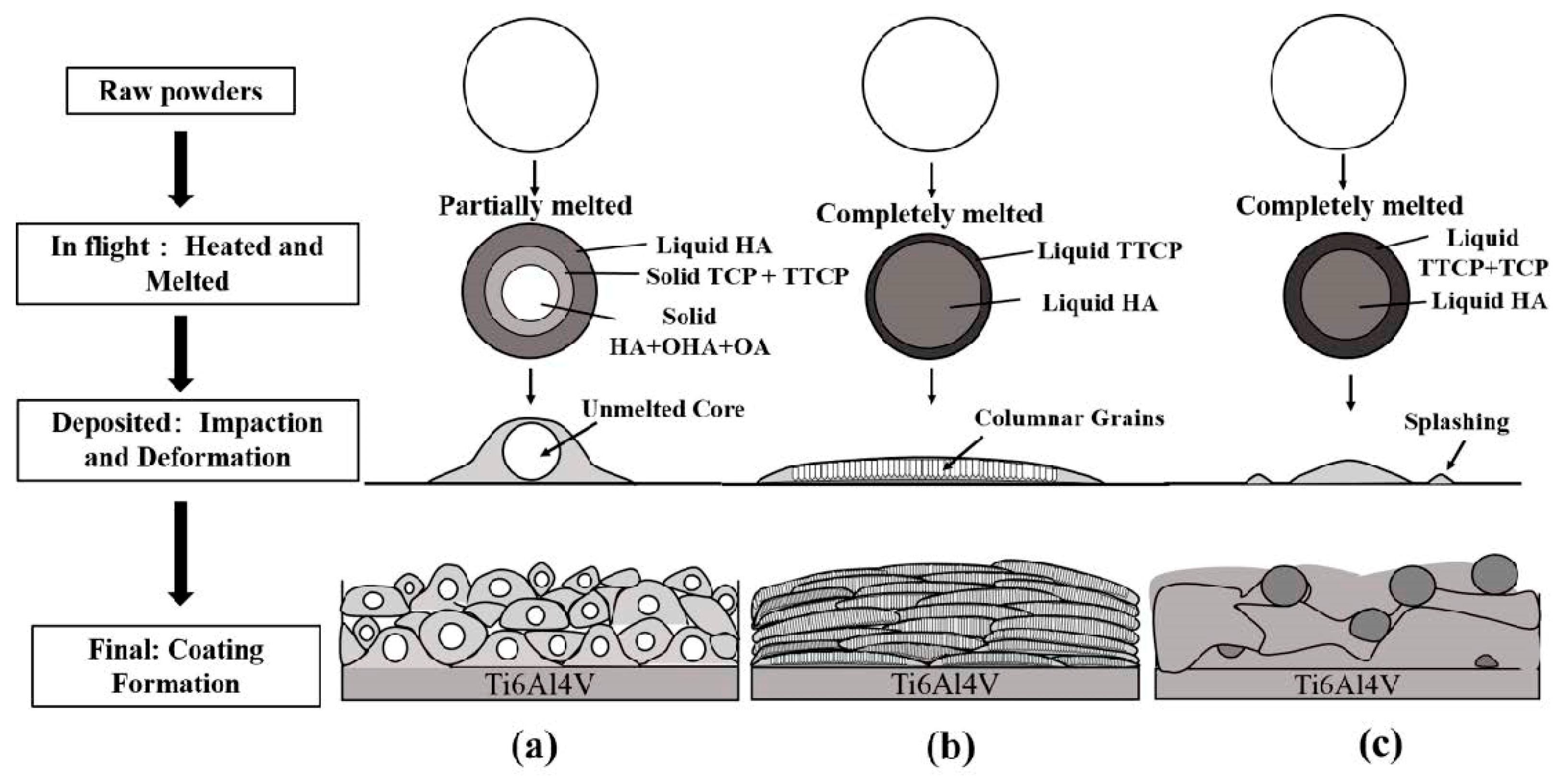
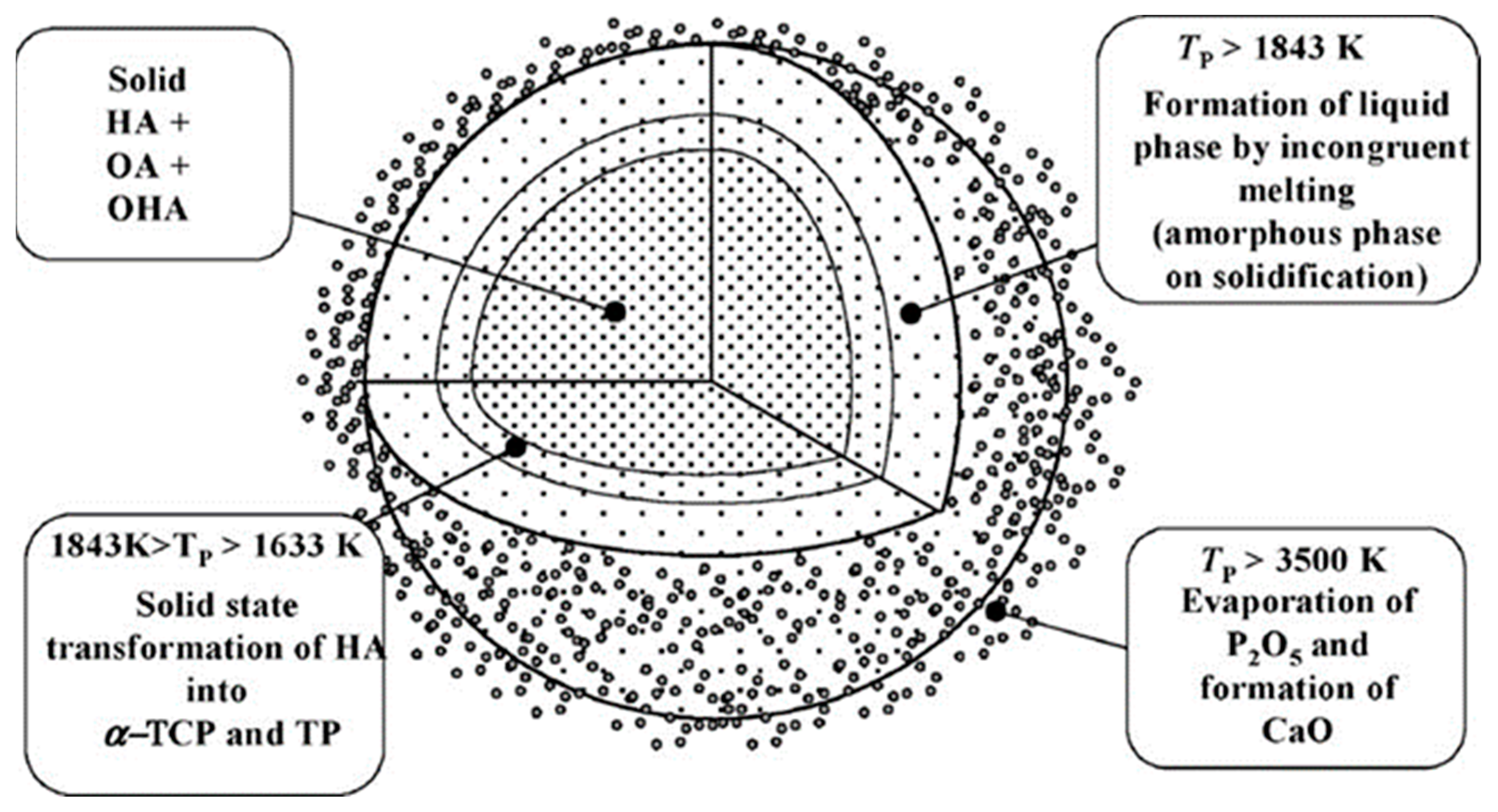
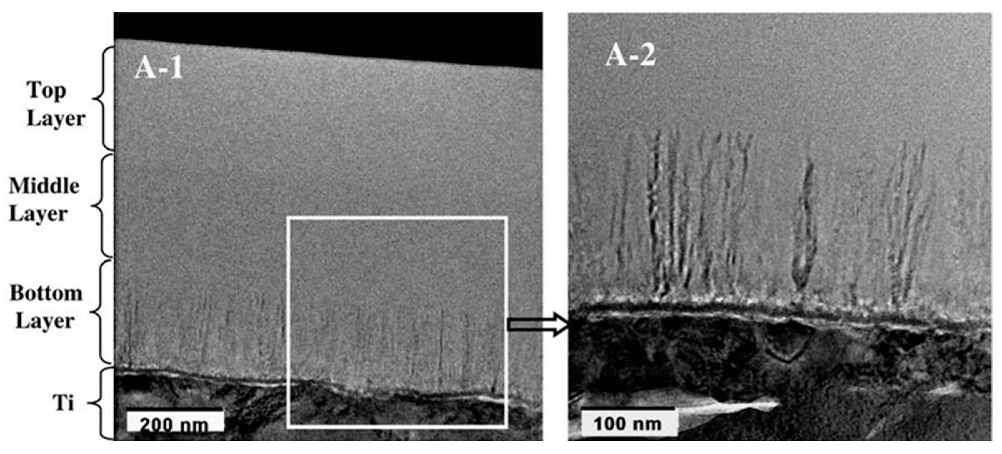
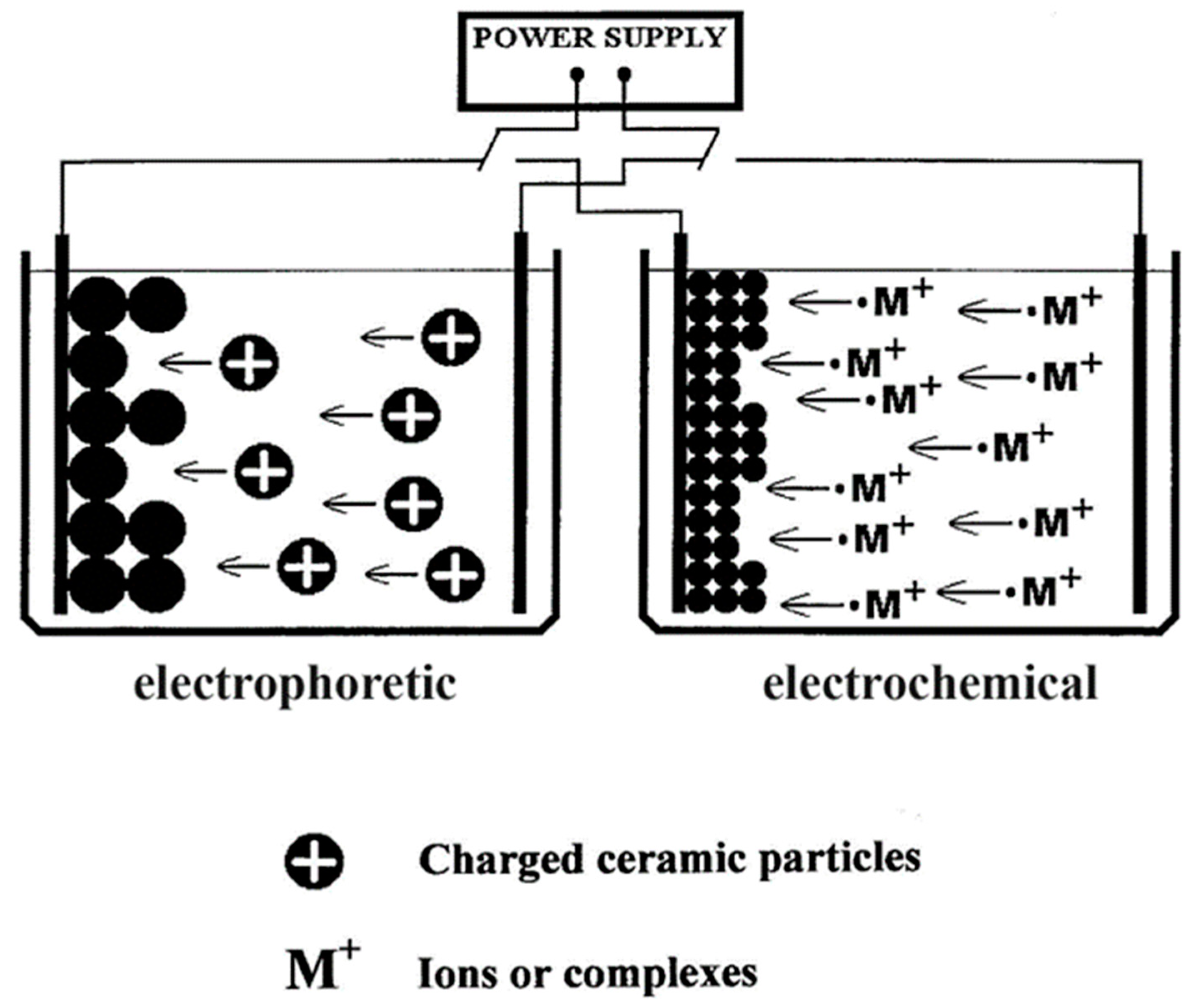
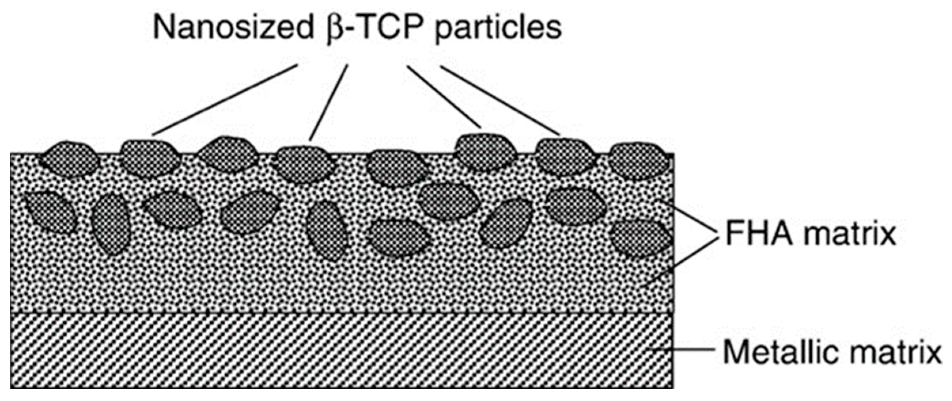
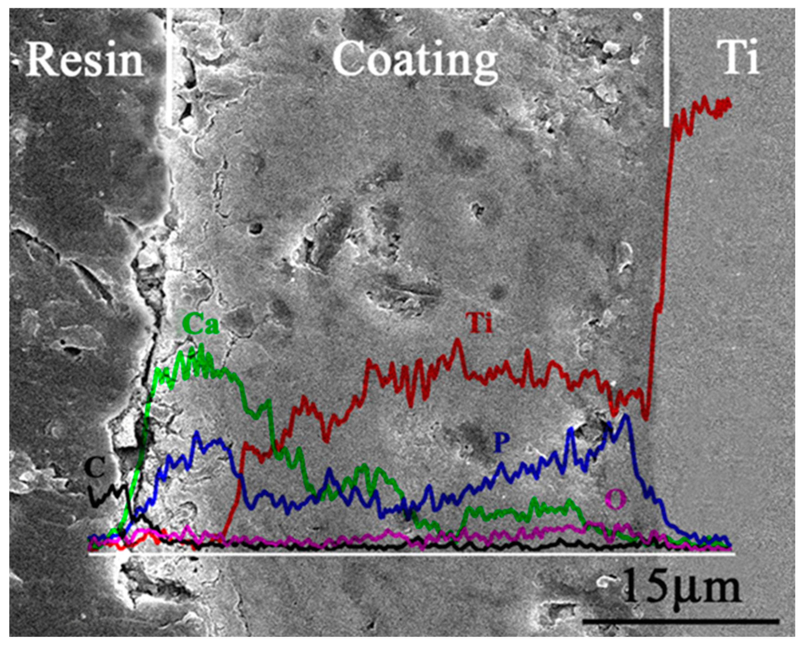
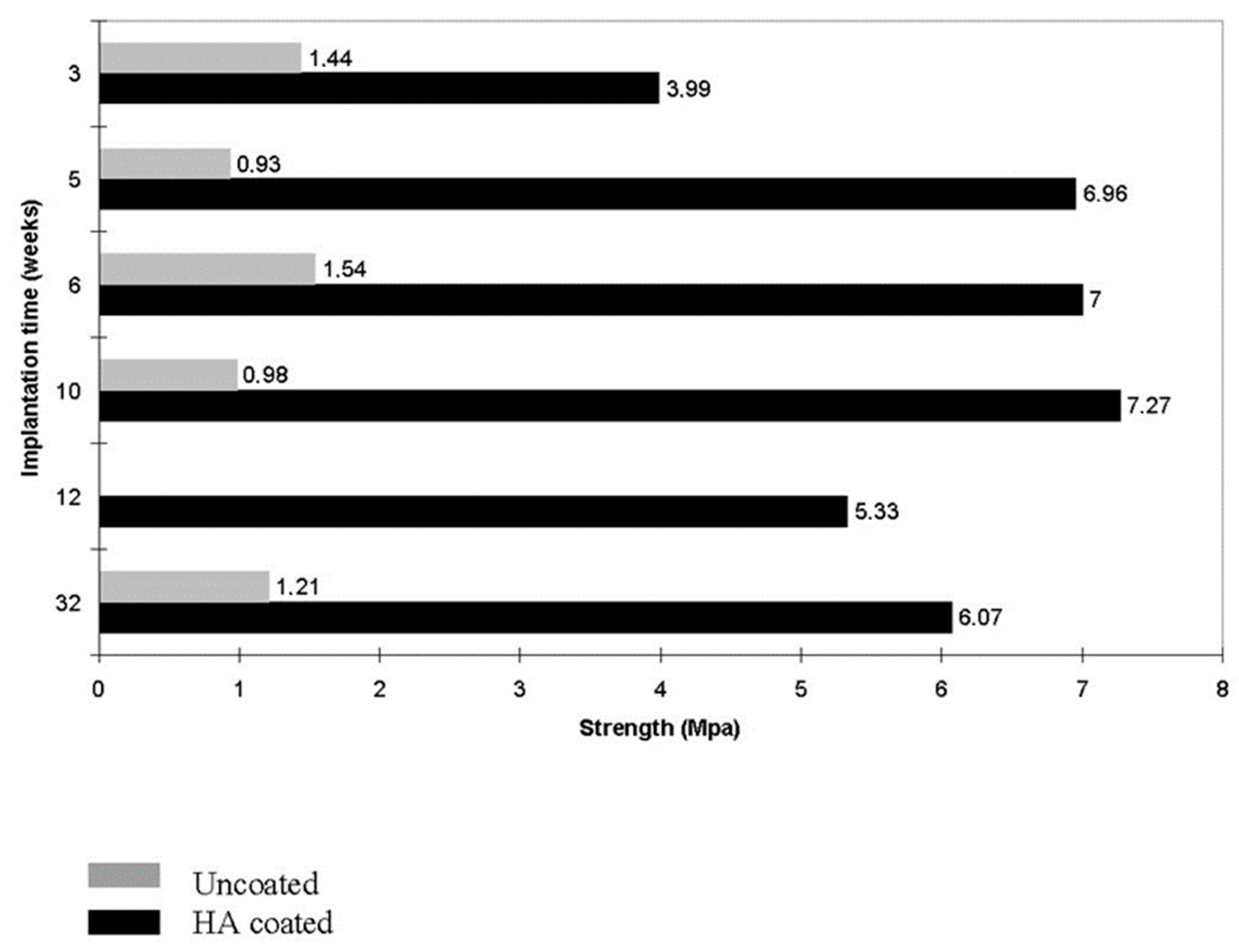
Figure 1. A schematic diagram showing the difference between formation of the conversion coatings and the deposited ones. Reproduced with permission from [29].
Jcs 07 00273 g001
Figure 2. A cross-sectional SEM image of a plasma-sputtered HA deposited onto a Ti bond coating over the surface of a Ti-6Al-4V alloy substrate. Reproduced with permission from [95].
Jcs 07 00273 g002
Figure 3. XRD patterns of (a)—initial HA powder, (b)—sprayed HA coating, (c)—HA coating heat treated at 600 °C (AH600) and (d)—HA coating hydrothermally treated at 150 °C (HT150). It can be easily seen that the crystallinity and phase purity of the poorly crystalline HA coatings are increased by both thermal and hydrothermal treatments. Reproduced with permission from [142].
Jcs 07 00273 g003
Figure 4. Typical surface morphologies of CaPO4 coatings sputtered onto glass substrates: (A) sputtered surface; (B) after 1 h annealing at 350 °C in the absence of water vapor; (C) after 1 h annealing at 350 °C in the presence of water vapor. Reproduced with permission from [28].
Jcs 07 00273 g004
Figure 5. Typical topographic morphologies of single flame-sprayed CaPO4 splats deposited onto Ti substrates preheated to various temperatures: (A)—no preheating (ambient conditions), (B)—preheated to 100 °C, (C)—preheated to 300 °C. Reproduced with permission from [174].
Jcs 07 00273 g005
Figure 6. A scanning electron micrograph of a typical plasma-sprayed HA coating on a titanium implant. As seen in the image, the morphology of the coating has a rough relief resulting from the presence of drops of different sizes in the flux. The bar is 10 µm. Reproduced with permission from [180].
Jcs 07 00273 g006
Figure 7. A schematic representation of splat type single particles during plasma spraying: (a) hemispherical shape splat; (b) oblate spheroidal splat; (c) disk; (d) splashed shape splat; (e) hemispherical shape splat. Reproduced with permission from [239].
Jcs 07 00273 g007
Figure 8. Phase formation in plasma sprayed HA deposits. The process steps show different melt chemistries as a function of particle temperature: (a) HA deposits contain many partially melted particles, (b) HA deposits with columnar structure, (c) HA deposits with a high amount of ACP. Reproduced with permission from [239].
Jcs 07 00273 g008
Figure 9. The temperature and assumed phase composition within a single plasma sprayed HA powder particle. Reproduced with permission from [242].
Jcs 07 00273 g009
Figure 10. A TEM image of a sputtered HA coating, showing the interface between the molten and unmelted portions within the HA splat, and the different grain sizes. Reproduced with permission from [248].
Jcs 07 00273 g010
Figure 11. Two optical micrographs of CaPO4 deposits on Si wafers: (a) without ion beam irradiation, (b) with Ar+ ion beam irradiation (120 V, 0.8 A). Reproduced with permission from [264].
Jcs 07 00273 g011
Figure 12. XRD patterns of fully crystallized (after a heat treatment at 1200 °C) CaPO4 coatings sputtered at three different ion beam current densities. Reproduced with permission from [308].
Jcs 07 00273 g012
Figure 13. TEM images of cross-sections of CaPO4 deposits on Ti substrates heated to various temperatures: 650 °C, 550 °C and 450 °C. (A-1) is an image of a cross-section containing both Ti and the coating, while (A-2) is a higher magnification image of an area showing only the interface and the crystal layer. The ~190 nm thick layer closest to the substrate was deposited at 650 °C. This layer shows a columnar crystal structure with 4–30 nm wide crystal grains perpendicular to the interface. The middle semi-crystalline layer with a thickness of ~226 nm was deposited at 550 °C and the upper amorphous layer with a thickness of ~278 nm was deposited at 450 °C. Reproduced with permission from [268].
Jcs 07 00273 g013
Figure 14. (A) Schematic of the ECR plasma spray system; (B) magnetic field strength as a function of distance from the plasma source tip. Reproduced with permission from [342].
Jcs 07 00273 g014
Figure 15. Schematic diagrams of electrophoretic and electrochemical deposition showing the movement and deposition of positively charged ceramic particles (left photo) and M+ ions (right photo) on the cathode. Reproduced with permission from [425].
Jcs 07 00273 g015
Figure 16. Typical SEM images of electrochemically deposited CaPO4 coatings under different conditions: (a) pH = 4.2, 60 °C, 2 h; (b) pH = 4.2, 85 °C, 4 h; (c) pH = 6.0, 80 °C, 3 h; (d) pH = 6.0, 90 °C, 3 h; (e) pH = 6.0, 90 °C, 3 h, 0.01 M KCl added; and (f) pH = 6.0, 90 °C, 3 h, 1.00 M NaNO2 added. All scale bars 10 µm. Reproduced with permission from [431].
Jcs 07 00273 g016
Figure 17. A schematic drawing of biphasic deposits prepared by sol–gel method with nano-sized β-TCP particles embedded into a continuous coating of fluorinated HA (FHA). Reproduced with permission from [469].
Jcs 07 00273 g017
Figure 18. A photograph showing the application of the dip–dry deposition method onto metals. A stainless steel square and five porous (pore size ~500 µm) Ta samples in the upper half were treated eight times with supersaturated CaPO4 solution and then dried. The samples show that the deposited coatings are uniformly white. In contrast, the deposited sample in the lower half shows a metallic luster. Reproduced with permission from [55].
Jcs 07 00273 g018
Figure 19. A schematic diagram of a spin-coating technique.
Jcs 07 00273 g019
Figure 20. A schematic diagram of the alternate soaking deposition method. Reproduced with permission from [569].
Jcs 07 00273 g020
Figure 21. A schematic diagram illustrating a plausible mechanism for CDHA deposition on the surface of MAO (PEO)-produced anatase TiO2 deposits on Ti substrates pre-dipped in K2HPO4 followed by SBF. Reproduced with permission from [595].
Jcs 07 00273 g021
Figure 22. A cross-sectional morphology and elemental distribution of CaPO4 coatings deposited by MAO on Ti. Reproduced with permission from [600].
Jcs 07 00273 g022
Figure 23. Proposed binding mechanisms for single CaPO4 particles during CS deposition: (a) impact consolidation at room temperature, (b) embedding or mechanical fixation, (c) chemical bonding. Reproduced with permission from reference [646].
Jcs 07 00273 g023
Figure 24. A schematic setup and a laser irradiation design (top left) used for a liquid phase laser deposition. Reproduced with permission from [705].
Jcs 07 00273 g024
Figure 25. A schematic representation of CaPO4 synthesis, CaPO4-Ti substrate mixed melt layer formation and CaPO4 deposition on Ti substrates using LISSC deposition technology. Green and red circles indicate Ca2+ and PO43− ions, respectively. HAp indicates HA. Reproduced with permission from [716].
Jcs 07 00273 g025
Figure 26. A scanning electron micrograph of electrostatic spray deposited CaPO4 coatings characterized by a porous surface morphology. Reproduced with permission from [723].
Jcs 07 00273 g026
Figure 27. A crystallization mushroom set up for CaPO4 deposition on mica muscovite sheets by VDSDM. Reproduced with permission from [753].
Jcs 07 00273 g027
Figure 28. A hypothetical mechanism of CaPO4 precipitation on Ti surface using PdCl2 as catalyst. Note that an intermediate layer of sodium titanate has been formed on Ti prior to CaPO4 precipitation. Reproduced with permission from [52].
Jcs 07 00273 g028
Figure 29. A schematic diagram of the galvanic deposition method. In this case, the sacrificial Zn anode is dissolved and CaPO4 is deposited on the surface of the cathode made of commercial stainless steel 316LSS (<0.03% C, 16–18.5% Cr, 10–14% Ni, 2–3% Mo, <2% Mn, <1% Si, <0.045% P, <0.03% S and Fe in equilibrium). Reproduced with permission from [762].
Jcs 07 00273 g029
Figure 30. Representative optical micrographs (background) and schematic diagrams (inset) of dichloromethane emulsions of PLLA stabilized with nanoscale HA in water (left) and preparation of nanoscale HA-coated PLLA microspheres after dichloromethane evaporation (right). Reproduced with permission from [771].
Jcs 07 00273 g030
Figure 31. A schematic diagram of the sonocoating process. Reproduced with permission from [796].
Jcs 07 00273 g031
Figure 32. Comparison of CaPO4 deposits prepared by different methods. Abbreviations: CVD—chemical vapor deposition; EHD—electrohydrodynamic coating; EPD—electrophoretic deposition; IBAD—ion beam assisted deposition; MAO—micro-arc oxidation; PVDMS—physical vapor deposition magnetron sputtering; PLD—pulsed laser deposition; SIM—surface-induced mineralization. Reproduced with permission from [883].
Jcs 07 00273 g032
Figure 33. A typical morphology of the fracture surface of a CaPO4 deposit. The image on the left shows a typical adhesive fracture where part of the coating has detached from the substrate. In the image on the right, a cohesive failure is observed. This occurs within the coating and is a mottled delamination on the surface of the remaining coating. Reproduced with permission from [808].
Jcs 07 00273 g033
Figure 34. Three different possible deposition states on substrate asperities depending on the size and shape of the fully fused HA (denoted as HAp) particles affecting their adhesion to the substrate. Reproduced with permission from [187].
Jcs 07 00273 g034
Figure 35. A schematic diagram of a standardized tensile adhesion measurement.
Jcs 07 00273 g035
Figure 36. The bond strength values of HA deposits on Ti-6Al-4V alloy specimens by various techniques. Reproduced with permission from [930].
Jcs 07 00273 g036
Figure 37. Schematic diagram showing the dissolution–precipitation behavior of individual HVOF sputtering HA splashes. It can be seen that the surrounding molten and subsequently solidified areas are almost completely dissolved, leaving only the unmelted HA core; (-1) belongs to the original splat and (-2) is the corresponding aged morphology. Compared to (a), in (b) the decrease in HA particle size leads to more conformability. Reproduced with permission from [956].
Jcs 07 00273 g037
Figure 38. A schematic diagram of the processes occurring in plasma sprayed CaPO4 deposits immersed in aqueous solutions: (a) disintegration (intergranular dissolution), (b) dissolution of the soluble phases (e.g., ACP) and precipitation of the less soluble phases (e.g., CDHA), (c) hydrolysis of the metastable phase (e.g., OA), (d) partial dissolution, (e) precipitation from supersaturated solutions (e.g., SBF), (f) hydrolysis of CaO and subsequent dissolution of Ca(OH)2. Adapted with permission from [225].
Jcs 07 00273 g038
Figure 39. Water contact angle measurements of (a) uncoated and (b) HA-coated Ti samples. Reproduced with permission from [394].
Jcs 07 00273 g039
Figure 40. Osteointegration properties of uncoated (left) and CaPO4-biomimetic coated metal implants (right) are compared after 6 weeks of implantation in goat femurs. Reproduced with permission from [180].
Jcs 07 00273 g040
Figure 41. A demonstration of how plasma-sprayed HA coatings on porous titanium (black rods) increase interfacial bond strength compared to uncoated porous titanium (grey rods) depending on implantation time. Reproduced with permission from [1105].
Jcs 07 00273 g041
Table 1. Existing calcium orthophosphates and their major properties [5,6].
Ca/P Molar RatioCompoundFormulaSolubility at
25 °C, −log(Ks)
Solubility at
25 °C, g/L
pH Stability Range in Aqueous Solutions at 25 °C
0.5Monocalcium phosphate monohydrate (MCPM)Ca(H2PO4)2·H2O1.14~180.0–2.0
0.5Monocalcium phosphate anhydrous (MCPA or MCP)Ca(H2PO4)21.14~17c
1.0Dicalcium phosphate dihydrate (DCPD), mineral brushiteCaHPO4·2H2O6.59~0.0882.0–6.0
1.0Dicalcium phosphate anhydrous (DCPA or DCP), mineral monetiteCaHPO46.90~0.048c
1.33Octacalcium phosphate (OCP)Ca8(HPO4)2(PO4)4·5H2O96.6~0.00815.5–7.0
1.5α-Tricalcium phosphate (α-TCP)α-Ca3(PO4)225.5~0.0025a
1.5β-Tricalcium phosphate (β-TCP)β-Ca3(PO4)228.9~0.0005a
1.2–2.2Amorphous calcium phosphates (ACP)CaxHy(PO4)z·nH2O, n = 3–4.5; 15–20% H2Obb~5–12 d
1.5–1.67Calcium-deficient hydroxyapatite (CDHA or Ca-def HA) eCa10-x(HPO4)x(PO4)6-x(OH)2-x (0 < x < 1)~85~0.00946.5–9.5
1.67Hydroxyapatite (HA, HAp or OHAp)Ca10(PO4)6(OH)2116.8~0.00039.5–12
1.67Fluorapatite (FA or FAp)Ca10(PO4)6F2120.0~0.00027–12
1.67Oxyapatite (OA, OAp or OXA) f, mineral voelckeriteCa10(PO4)6O~69~0.087a
2.0Tetracalcium phosphate (TTCP or TetCP), mineral hilgenstockiteCa4(PO4)2O38–44~0.0007a
a These compounds cannot be precipitated from aqueous solutions. b Cannot be measured precisely. However, the following values were found: 25.7 ± 0.1 (pH = 7.40), 29.9 ± 0.1 (pH = 6.00), 32.7 ± 0.1 (pH = 5.28). The comparative extent of dissolution in acidic buffer is: ACP >> α-TCP >> β-TCP > CDHA >> HA > FA. c Stable at temperatures above 100 °C. d Always metastable. e Occasionally, it is called “precipitated HA (PHA)”. f Existence of OA remains questionable.
Table 2. FDA requirements for HA coatings [16].
PropertiesSpecification
ThicknessNot specific
Crystallinity62% minimum
Phase purity95% minimum
Ca/P atomic ratio1.67–1.76
Density2.98 g/cm3
Heavy metals<50 ppm
Tensile strength>50.8 MPa
Shear strength>22 MPa
AbrasionNot specific
Table 3. A mutual comparison of several deposition techniques of calcium orthophosphate coatings, films and layers on various substrates [28,29,30].
TechniqueThicknessAdvantagesDisadvantages
Plasma spraying30–200 μmA simple and flexible technique; uniform and smooth coatings are produced; high deposition rates; low costLine-of-sight technique; high temperatures induce partial decomposition and formation of non-stoichiometric and amorphous compounds; expensive equipment; simultaneous incorporation of biological agents is impossible; rapid cooling produces cracks
Flame spraying100–250 μmMost economical among all thermal spraying techniques; easily adaptable; porous depositsLine-of-sight technique; high temperatures induce partial decomposition and formation of non-stoichiometric and amorphous compounds; crack development at lower temperatures, simultaneous incorporation of biological agents is impossible; rapid cooling produces cracks
High velocity oxy-fuel spraying30–200 µmHigh deposition rates; uniform deposition; improved wear and corrosion resistance and biocompatibility; no post treatment requiredLine-of-sight technique; high temperatures induce partial decomposition and formation of non-stoichiometric and amorphous compounds; simultaneous incorporation of biological agents is impossible; rapid cooling produces cracks
RF magnetron sputtering0.5–3 μmUniform coating thickness on flat substrates; high purity and adhesion; dense pore-free deposits; excellent coverage of steps and small features; ability to coat heat-sensitive substratesLine-of-sight technique; expensive; low deposition rates; produces amorphous coatings; high temperatures prevent from simultaneous incorporation of biological agents
Pulsed laser deposition (laser ablation)0.05–5 μmCoatings with crystalline and amorphous phases; dense and porous coatings; high adhesive strength; ability to produce wide range of multilayer coatings from different materialsLine-of-sight technique; expensive; high temperatures prevent simultaneous incorporation of biological agents; lack of uniformity
Ion beam assisted deposition0.05–1 µmUniform coating thickness; high reproducibility and reliability; dense; high adhesion; wide atomic intermix zone at the coating/substrate interfaceLine-of-sight technique; expensive; produces amorphous coatings
Sputtering0.5–3 μmUniform coating thickness on flat substrates; dense; high adhesionLine-of-sight technique; expensive equipment; time-consuming; produces amorphous coatings
Electrostatic spray deposition10 nm–30 μmLow cost; easy set-up; ambient conditions; a wide choice of both precursors (dissolved salts, suspensions, sols) and substratesLine-of-sight technique; problems coating large surfaces; low flow rates; requires high temperatures to decompose the precursor solvents and salts
Dip coating2 μm –5 mmEasy set-up; low cost; coatings applied quickly; can coat complex substratesRequires high sintering temperatures; possible thermal expansion mismatch; crack appearance
Spin coating2 μm–0.5 mmEasy set-up; low cost; coatings applied quicklyRequires high sintering temperatures; possible thermal expansion mismatch; crack appearance; cannot coat complex substrates
Sol–gel technique<1 μmCan coat complex shapes; low processing temperatures; thin coatings; inexpensive process; can incorporate biological moleculesSome processes require controlled atmosphere processing; expensive raw materials; high permeability; low wear resistance; hard to control the porosity
Electrophoretic deposition0.1–2.0 mmUniform coating thickness; rapid deposition rates; simple setup; low cost; can coat complex substrates; can incorporate biological moleculesDifficult to produce crack-free coatings; requires post treatment at high temperatures
Electrochemical (cathodic) deposition0.05–0.5 mmGood shape conformity; room temperature process; uniform coating thickness; short processing times; can incorporate biological moleculesSometimes stressed coatings are produced, leading to their poor adhesion with substrate; requires good control of electrolyte parameters
Biomimetic process<30 μmLow processing temperatures; can form bonelike apatite; can coat complex shapes; can incorporate biological moleculesVery low deposition rates; requires replenishment and a pH constancy of the simulating solutions (HBSS, SBF, etc.)
Hydrothermal deposition0.2–2.0 μmCoatings are crystalline; can coat complex shapesHigh pressure and temperatures are required
Thermal substrate deposition0.2–2.0 μmDeposition is enhanced by heat and current; different CaPO4 phases can be formedLess common technique; coatings of diverse crystallinities are produced
Hot isostatic pressing0.2–2.0 μmProduces dense coatings; homogeneous structure; high uniformity; high precision; no dimensional or shape limitationsCannot coat complex substrates; high temperature required; thermal expansion mismatch; elastic property differences; expensive; removal/interaction of encapsulation material; high temperatures prevent simultaneous incorporation of biological agents
Micro-arc oxidation3–30 μmSimple, economical and environmentally friendly technique, suitable for coating of complex geometriesUnless the proper electrolytes are used, the procedure rather should be considered as a pre-deposition technique onto which CaPO4 are deposited by other methods
Dynamic mixing method0.05–1.3 μmHigh adhesive strengthLine-of-sight technique; expensive; produces amorphous coatings
Disclaimer/Publisher’s Note: The statements, opinions and data contained in all publications are solely those of the individual author(s) and contributor(s) and not of MDPI and/or the editor(s). MDPI and/or the editor(s) disclaim responsibility for any injury to people or property resulting from any ideas, methods, instructions or products referred to in the content.

