
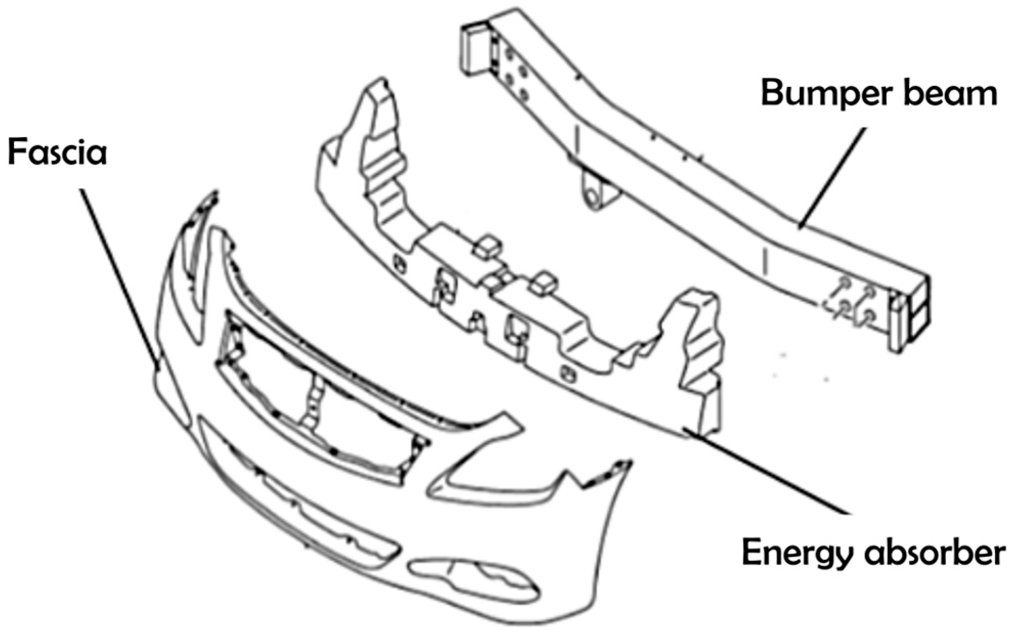
Composite Plastic Hybrid for Automotive Front Bumper Beam


Abstract
:1. Introduction
2. Experimental Program and Settings
2.1. Material Selection
2.2. Specimen Preparation
2.3. Low-Velocity Impact (LVI)
3. Results and Discussion
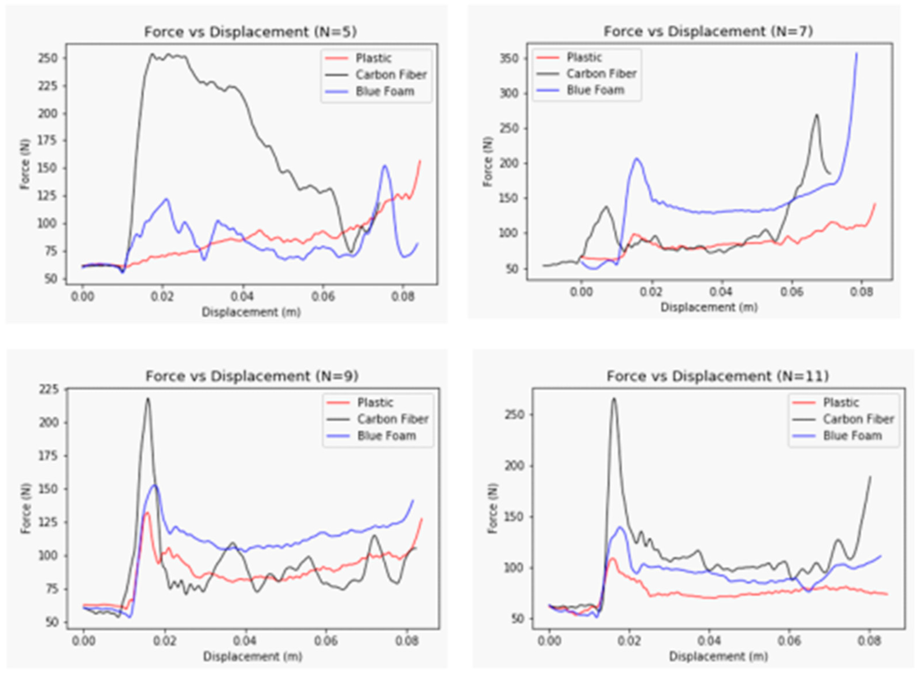
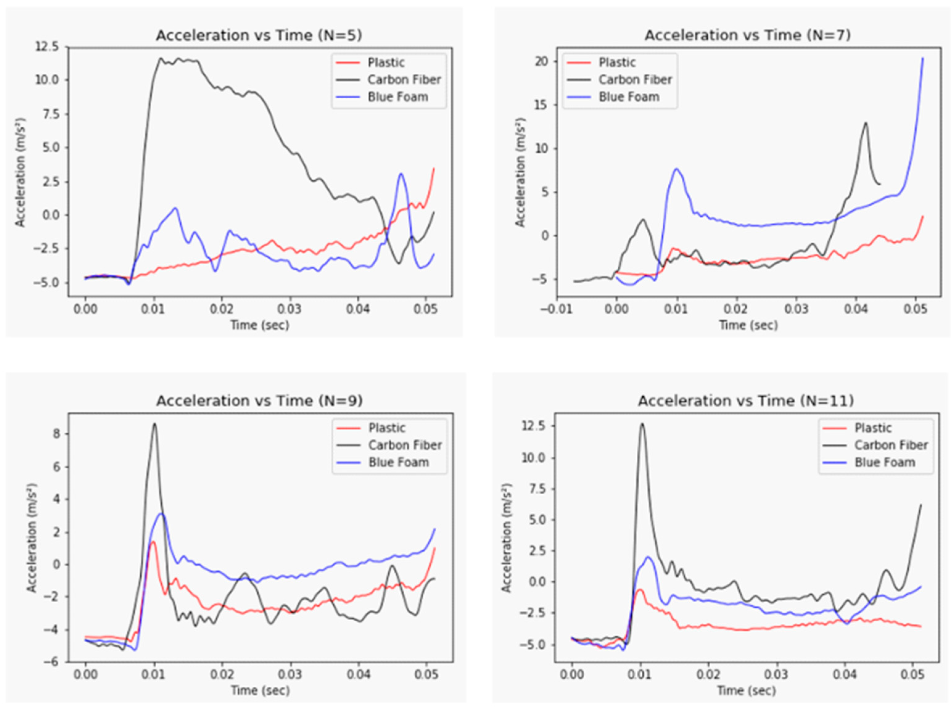
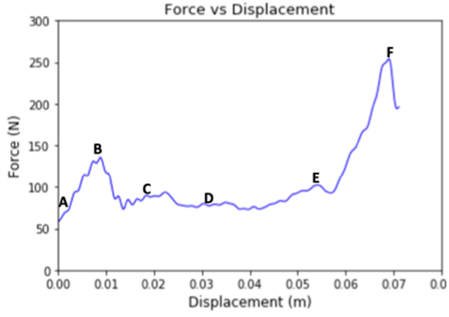
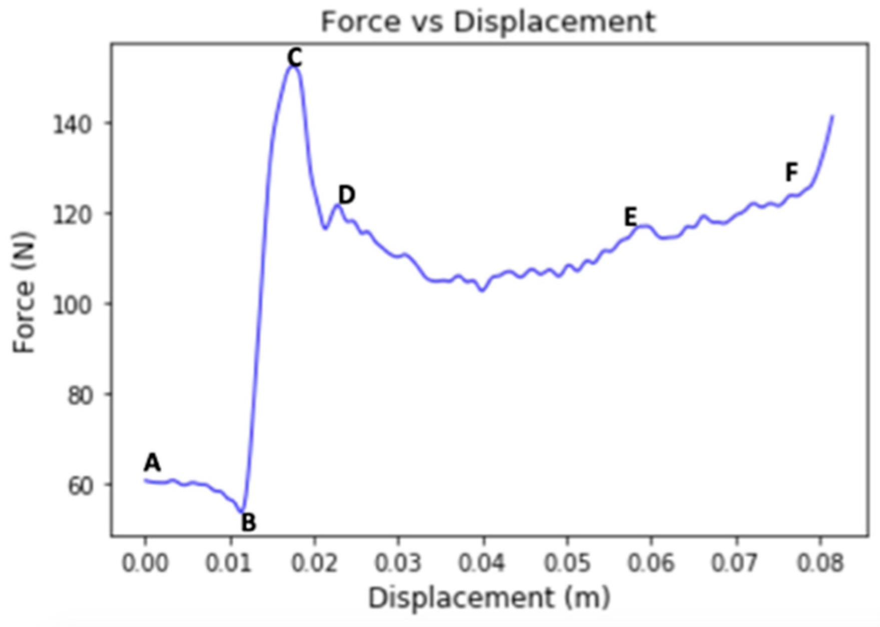
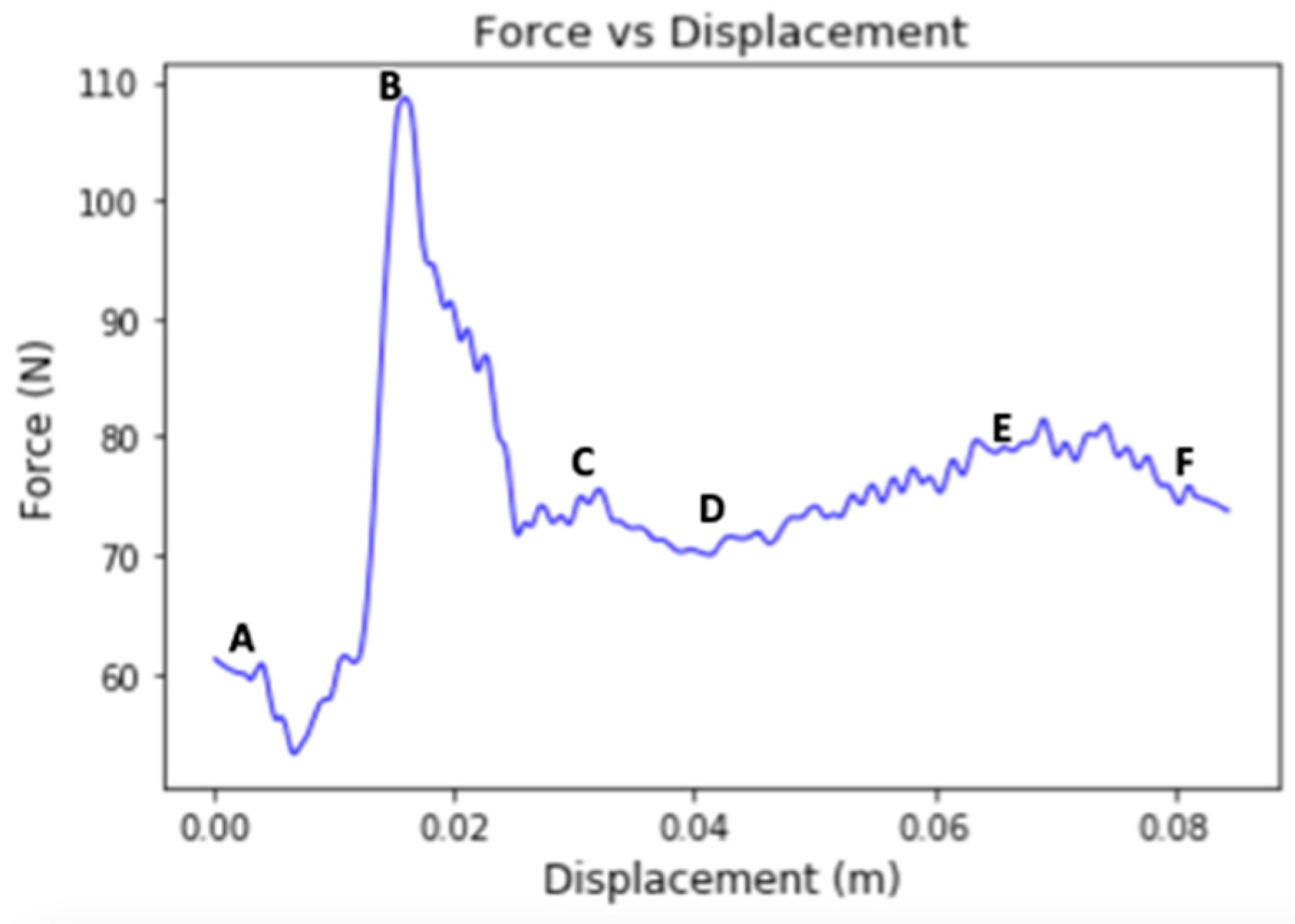
3.1. Impact Performance
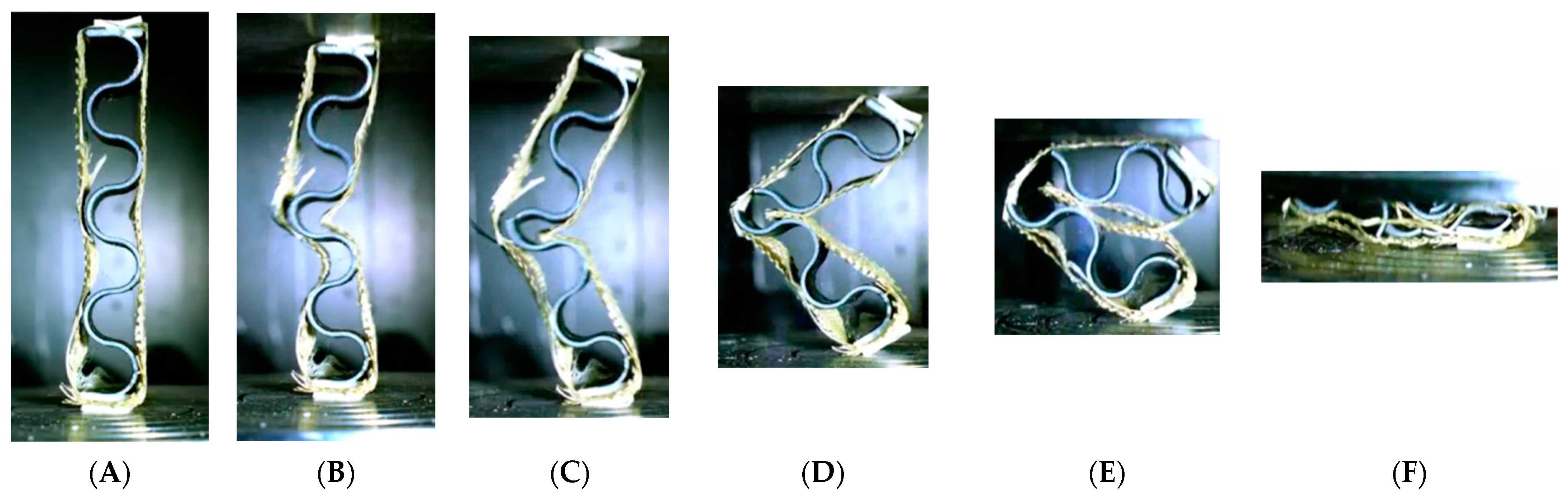
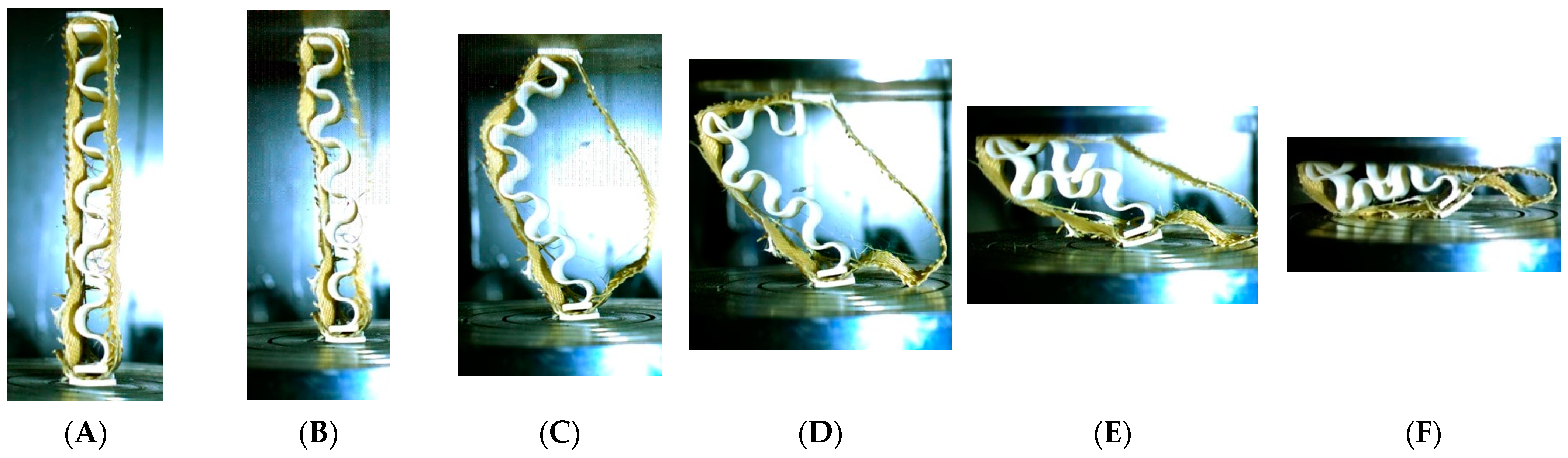
3.2. Structure Recoverability
3.3. Structural Failure Analysis
4. Variability Analysis: Energy Absorption Versus Composition Type
5. Conclusions
Author Contributions
Funding
Data Availability Statement
Conflicts of Interest
References
- World Health Organization. Global Status Report on Road Safety 2018; World Health Organization: Geneva, Switzerland, 2019. [Google Scholar]
- Pathological Aspects and Associated Biodynamics in Aircraft Accident Investigation (Les Aspects Pathologiques et la Biodynamique Associee dans les Enquetes sur les Accidents D’aeronefs) (CD-ROM). Available online: https://apps.dtic.mil/sti/citations/ADM001834 (accessed on 20 February 2023).
- Alkhatib, F.; Mahdi, E.; Dean, A. Design and Evaluation of Hybrid Composite Plates for Ballistic Protection: Experimental and Numerical Investigations. Polymers 2021, 13, 1450. [Google Scholar] [CrossRef] [PubMed]
- Alkhatib, F.; Mahdi, E.; Dean, A. Crushing response of CFRP and KFRP composite corrugated tubes to quasi-static slipping axial loading: Experimental investigation and numerical simulation. Compos. Struct. 2020, 246, 112370. [Google Scholar] [CrossRef]
- Alkhatib, F.; Mahdi, E.; Dean, A. Development of composite double-hat energy absorber device subjected to traverser loads. Compos. Struct. 2020, 240, 112046. [Google Scholar] [CrossRef]
- Mahdi, E.; Hamouda, A. Energy absorption capability of composite hexagonal ring systems. Mater. Des. 2012, 34, 201–210. [Google Scholar] [CrossRef]
- Abdewi, E.F.; Sulaiman, S.; Hamouda, A.; Mahdi, E. Effect of geometry on the crushing behaviour of laminated corrugated composite tubes. J. Mater. Process. Technol. 2006, 172, 394–399. [Google Scholar] [CrossRef]
- Mohammadi, H.; Ahmad, Z.; Mazlan, S.A.; Johari, M.A.F.; Siebert, G.; Petrů, M.; Koloor, S.S.R. Lightweight Glass Fiber-Reinforced Polymer Composite for Automotive Bumper Applications: A Review. Polymers 2022, 15, 193. [Google Scholar] [CrossRef] [PubMed]
- Godara, S.; Nagar, S.N. Analysis of frontal bumper beam of automobile vehicle by using carbon fiber composite material. Mater. Today Proc. 2020, 26, 2601–2607. [Google Scholar] [CrossRef]
- Sun, G.; Wang, X.; Fang, J.; Pang, T.; Li, Q. Parallelized optimization design of bumper systems under multiple low-speed impact loads. Thin-Walled Struct. 2021, 167, 108197. [Google Scholar] [CrossRef]
- Beyene, A.; Koricho, E.; Belingardi, G.; Martorana, B. Design and Manufacturing Issues in the Development of Lightweight Solution for a Vehicle Frontal Bumper. Procedia Eng. 2014, 88, 77–84. [Google Scholar] [CrossRef] [Green Version]
- Wang, C.; Wang, W.; Zhao, W.; Wang, Y.; Zhou, G. Structure design and multi-objective optimization of a novel NPR bumper system. Compos. Part B Eng. 2018, 153, 78–96. [Google Scholar] [CrossRef]
- Natarajan, N.; Joshi, P.; Tyagi, R. Design improvements of vehicle bumper for low speed impact. Mater. Today Proc. 2020, 38, 456–465. [Google Scholar] [CrossRef]
- Lei, F.; Lv, X.; Fang, J.; Li, Q.; Sun, G. Nondeterministic multi-objective and multi-case discrete optimization of functionally-graded front-bumper structures for pedestrian protection. Thin-Walled Struct. 2021, 167, 106921. [Google Scholar] [CrossRef]
- Belingardi, G.; Beyene, A.T.; Koricho, E.G.; Martorana, B. 12—Lightweight solutions for vehicle frontal bumper: Crash design and manufacturing issues. In Dynamic Response and Failure of Composite Materials and Structures; Woodhead Publishing: Cambridge, UK, 2017. [Google Scholar] [CrossRef]
- Marzbanrad, J.; Alijanpour, M.; Kiasat, M.S. Design and analysis of an automotive bumper beam in low-speed frontal crashes. Thin-Walled Struct. 2009, 47, 902–911. [Google Scholar] [CrossRef]
- Muhammad Nasiruddin, S.; Hambali, A.; Rosidah, J.; Widodo, W.S.; Ahmad, M.N. A Review of Energy Absorption of Automotive Bumper Beam. Int. J. Appl. Eng. Res. 2017, 12, 238–245. [Google Scholar]
- Bohra, B.A.; Pawar, D.B. Comparative analysis of frontal car bumper during impact. Int. J. Appl. Innov. Eng. Manag. 2014, 3, 89–93. [Google Scholar]
- Chege, A.; Kale, A.; Agrewale, M.R.B.; Vora, D.K.C. DESIGN AND DEVELOPMENT OF IMPACT ENERGY ABSORBING BUMPER. Int. J. Sci. Eng. Res. 2017, 8, 326–330. [Google Scholar]
- Mahdi, E.; Ochoa, D.R.H.; Vaziri, A.; Dean, A.; Kucukvar, M. Khalasa date palm leaf fiber as a potential reinforcement for polymeric composite materials. Compos. Struct. 2020, 265, 113501. [Google Scholar] [CrossRef]
- Dean, A.; Rolfes, R.; Grbic, N.; Hübner, S.; Behrens, B. A FEM-based virtual test-rig for hybrid metal-composites clinching joints. Mater. Und Werkst. 2019, 50, 973–986. [Google Scholar] [CrossRef]
- Dean, A. Material Modeling of Short Fiber Reinforced Polymeric Composites: Theory, Numerical Aspects, and Applications; ISD, Institut für Statik und Dynamik: Hanover, Germany, 2017. [Google Scholar]
- Dean, A.; Sahraee, S.; Reinoso, J.; Rolfes, R. Finite deformation model for short fiber reinforced composites: Application to hybrid metal-composite clinching joints. Compos. Struct. 2016, 151, 162–171. [Google Scholar] [CrossRef]
- Gerendt, C.; Dean, A.; Mahrholz, T.; Englisch, N.; Krause, S.; Rolfes, R. On the progressive fatigue failure of mechanical composite joints: Numerical simulation and experimental validation. Compos. Struct. 2020, 248, 112488. [Google Scholar] [CrossRef]
- Wang, B.; Zhang, Z.; Xu, G.; Zeng, X.; Hu, W.; Matsubae, K. Wrought and cast aluminum flows in China in the context of electric vehicle diffusion and automotive lightweighting. Res. Conserv. Recycl. 2023, 191, 106877. [Google Scholar] [CrossRef]
- Gonçalves, M.; Monteiro, H.; Iten, M. Life Cycle Assessment studies on lightweight materials for automotive applications—An overview. Energy Rep. 2022, 8, 338–345. [Google Scholar] [CrossRef]
- Ramasubramanian, S.; Tennis, K. Lightweight material for weight reductions in an automotive suspension part lower link. Mater. Today Proc. 2023, in press. [Google Scholar] [CrossRef]
- Ganesarajan, D.; Simon, L.; Tamrakar, S.; Kiziltas, A.; Mielewski, D.; Behabtu, N.; Lenges, C. Hybrid composites with engineered polysaccharides for automotive lightweight. Compos. Part C Open Access 2021, 7, 100222. [Google Scholar] [CrossRef]
- Gardie, E.; Paramasivam, V.; Dubale, H.; Chekol, E.T.; Selvaraj, S.K. Numerical analysis of reinforced carbon fiber composite material for lightweight automotive wheel application. Mater. Today Proc. 2021, 46, 7369–7374. [Google Scholar] [CrossRef]
- Wegmann, S.; Rytka, C.; Diaz-Rodenas, M.; Werlen, V.; Schneeberger, C.; Ermanni, P.; Caglar, B.; Gomez, C.; Michaud, V. A life cycle analysis of novel lightweight composite processes: Reducing the environmental footprint of automotive structures. J. Clean. Prod. 2021, 330, 129808. [Google Scholar] [CrossRef]
- Zhang, W.; Xu, J. Advanced lightweight materials for Automobiles: A review. Mater. Des. 2022, 221, 110994. [Google Scholar] [CrossRef]
- Junk, S.; Rothe, N. Lightweight design of automotive components using generative design with fiber-reinforced additive manufacturing. Procedia CIRP 2022, 109, 119–124. [Google Scholar] [CrossRef]
- Liu, B.; Yang, J.; Zhang, X.; Yang, Q.; Zhang, J.; Li, X. Development and application of magnesium alloy parts for automotive OEMs: A review. J. Magnes. Alloy. 2023, 11, 15–47. [Google Scholar] [CrossRef]
- McCrum, N.G.; Buckley, C.P.; Bucknall, C.B.; McCrum, N.G.; Buckley, C.P.; Bucknall, C.B. Principles of Polymer Engineering, 2nd ed.; Oxford University Press: Oxford, NY, USA, 1997. [Google Scholar]
- Snyder, R.G. Human Impact Tolerance. SAE Trans. 1970, 79, 1375–1452. [Google Scholar]
- Chou, C.C.; Bois, P.D.; Fileta, B.B.; Khalil, T.B.; King, A.I.; Mahmood, H.F.; Mertz, H.J.; Wismans, J. Vehicle Crashworthiness and Occupant Protection. Available online: https://roadsafellc.com/NCHRP22-24/Literature/Papers/Vehicle%20Crashworthiness%20and%20Occupant%20Protection(Book).pdf (accessed on 28 March 2023).
- Prasad, P. Biomechanical Basis for Injury Criteria Used in Crashworthiness Regulations: ‘Bertil Aldman Award’ Lecture. 1999. Available online: https://www.semanticscholar.org/paper/BIOMECHANICAL-BASIS-FOR-INJURY-CRITERIA-USED-IN-Prasad/986c44c84ab9b2b78c3f61362b3ab052a31aa239 (accessed on 28 March 2023).
- Shopping for Safety: Providing Consumer Automotive Safety Information. Transp. Res. Board Spec. Rep. 1996. Available online: https://trid.trb.org/View/462475 (accessed on 28 March 2023).
- Zini, G. Reduction of Crash Severity Through In-Vehicle Systems (IVS) Speed Control; University of Buenos Aires: Buenos Aires, Argentina, 2005. [Google Scholar]
- Raju, K.; Rao, K.N.; Santhosh, T.R.; Krupa, C.S. Bumper Beams is Absorbing the Bulk of Energy and Providing Protection to the Rest of the Vehicle; St. Martins Engineering College: Secunderabad, India, 2015. [Google Scholar]
- Cheon, S.S.; Choi, J.H.; Gil Lee, D. Development of the composite bumper beam for passenger cars. Compos. Struct. 1995, 32, 491–499. [Google Scholar] [CrossRef]
- Du, B.; Li, Q.; Zheng, C.; Wang, S.; Gao, C.; Chen, L. Application of Lightweight Structure in Automobile Bumper Beam: A Review. Materials 2023, 16, 967. [Google Scholar] [CrossRef] [PubMed]
- Davoodi, M.; Sapuan, M.S.; Ahmad, D.; Aidy, A.; Ali, A.; Jonoobi, M. Concept selection of car bumper beam with developed hybrid bio-composite material. Mater. Des. 2011, 32, 4857–4865. [Google Scholar] [CrossRef]
- Hsissou, R.; Seghiri, R.; Benzekri, Z.; Hilali, M.; Rafik, M.; Elharfi, A. Polymer composite materials: A comprehensive review. Compos. Struct. 2021, 262, 113640. [Google Scholar] [CrossRef]
- Egorov, S.A.; Tarasova, T.V.; Terekhina, S.M. Production technology for polymeric composite materials by additive manufacturing methods. IOP Conf. Ser. Mater. Sci. Eng. 2020, 971, 022006. [Google Scholar] [CrossRef]
- Mahdi, E.; Dean, A. The Effect of Filler Content on the Tensile Behavior of Polypropylene/Cotton Fiber and poly(vinyl chloride)/Cotton Fiber Composites. Materials 2020, 13, 753. [Google Scholar] [CrossRef] [PubMed] [Green Version]
- Chichane, A.; Boujmal, R.; El Barkany, A. Bio-composites and bio-hybrid composites reinforced with natural fibers: Review. Mater. Today Proc. 2023, 72, 3471–3479. [Google Scholar] [CrossRef]
- Bi, X.; Huang, R. 3D printing of natural fiber and composites: A state-of-the-art review. Mater. Des. 2022, 222, 111065. [Google Scholar] [CrossRef]
- Ismail, S.O.; Akpan, E.; Dhakal, H.N. Review on natural plant fibres and their hybrid composites for structural applications: Recent trends and future perspectives. Compos. Part C Open Access 2022, 9, 100322. [Google Scholar] [CrossRef]
- Santhosh, N.; Selvam, S.; Reghu, R.; Sundaran, J.; Mathew, B.C.; Palanisamy, S. Mechanical properties studies on rubber composites reinforced with Acacia Caesia fibre. Mater. Today Proc. 2023, 72, 3172–3176. [Google Scholar] [CrossRef]
- Zaghloul, M.Y.M.; Zaghloul, M.M.Y.; Zaghloul, M.M.Y. Developments in polyester composite materials—An in-depth review on natural fibres and nano fillers. Compos. Struct. 2021, 278, 114698. [Google Scholar] [CrossRef]
- Dun, M.; Fu, H.; Hao, J.; Shan, W.; Wang, W. Tailoring flexible interphases in bamboo fiber-reinforced linear low-density polyethylene composites. Compos. Part A Appl. Sci. Manuf. 2021, 150, 106606. [Google Scholar] [CrossRef]
- Karthi, N.; Kumaresan, K.; Sathish, S.; Gokulkumar, S.; Prabhu, L.; Vigneshkumar, N. An overview: Natural fiber reinforced hybrid composites, chemical treatments and application areas. Mater. Today Proc. 2019, 27, 2828–2834. [Google Scholar] [CrossRef]
- Kim, J.-W.; Kim, H.-S.; Lee, D.-G. Manufacturing and Characterization of Glass Fiber/Polypropylene Prepreg for Automotive Bumper Beam. J. Comput. Theor. Nanosci. 2015, 12, 842–846. [Google Scholar] [CrossRef]
- Tarlochan, F.; Hamouda, A.M.S.; Mahdi, E.; Sahari, B.B. Composite sandwich structures for crashworthiness applications. Proc. Inst. Mech. Eng. Part L J. Mater. Des. Appl. 2007, 221, 121–130. [Google Scholar] [CrossRef]
- Hosseinzadeh, R.; Shokrieh, M.M.; Lessard, L.B. Parametric study of automotive composite bumper beams subjected to low-velocity impacts. Compos. Struct. 2005, 68, 419–427. [Google Scholar] [CrossRef]
- Zhang, Z.; Liu, S.; Tang, Z. Design optimization of cross-sectional configuration of rib-reinforced thin-walled beam. Thin-Walled Struct. 2009, 47, 868–878. [Google Scholar] [CrossRef]
- Zhang, X.; Wen, Z.; Zhang, H. Axial crushing and optimal design of square tubes with graded thickness. Thin-Walled Struct. 2014, 84, 263–274. [Google Scholar] [CrossRef]
- Zarei, H.; Kröger, M. Bending behavior of empty and foam-filled beams: Structural optimization. Int. J. Impact Eng. 2008, 35, 521–529. [Google Scholar] [CrossRef]
- Sinha, A.; Yadav, K.; Khurana, R.S. Design of Bumper Beam Structure for Pedestrian Protection and Low Speed Bumper Impact(ECE-R42); SAE Technical Paper 2016-01–1335; SAE International: Warrendale, PA, USA, 2016. [Google Scholar] [CrossRef]
- Singh, T.J.; Samanta, S. Characterization of Kevlar Fiber and Its Composites: A Review. Mater. Today Proc. 2015, 2, 1381–1387. [Google Scholar] [CrossRef]
- Rajesh, S.; Ramnath, B.V.; Jayasooriya, M.; Ragavan, R. Review on Mechanical Characteristics of Kevlar Composites. J. Mines Met. Fuels 2022, 387–394. [Google Scholar] [CrossRef]
- Eyvazian, A.; Taghizadeh, S.A.; Hamouda, A.M.; Tarlochan, F.; Moeinifard, M.; Gobbi, M. Buckling and crushing behavior of foam-core hybrid composite sandwich columns under quasi-static edgewise compression. J. Sandw. Struct. Mater. 2019, 23, 2643–2670. [Google Scholar] [CrossRef]
- Miao, H.; Wu, Z.; Ying, Z.; Hu, X. The numerical and experimental investigation on low-velocity impact response of composite panels: Effect of fabric architecture. Compos. Struct. 2019, 227, 111343. [Google Scholar] [CrossRef]
- Brod, M.; Dean, A.; Scheffler, S.; Gerendt, C.; Rolfes, R. Numerical modeling and experimental validation of fatigue damage in Cross-Ply CFRP composites under inhomogeneous stress states. Compos. Part B Eng. 2020, 200, 108050. [Google Scholar] [CrossRef]
- Kumar, P.A.V.; Dean, A.; Reinoso, J.; Paggi, M. A multi phase-field-cohesive zone model for laminated composites: Application to delamination migration. Compos. Struct. 2021, 276, 114471. [Google Scholar] [CrossRef]
- Dean, A.; Reinoso, J.; Jha, N.; Mahdi, E.; Rolfes, R. A phase field approach for ductile fracture of short fibre reinforced composites. Theor. Appl. Fract. Mech. 2020, 106, 102495. [Google Scholar] [CrossRef]
- Dean, A.; Kumar, P.A.V.; Reinoso, J.; Gerendt, C.; Paggi, M.; Mahdi, E.; Rolfes, R. A multi phase-field fracture model for long fiber reinforced composites based on the Puck theory of failure. Compos. Struct. 2020, 251, 112446. [Google Scholar] [CrossRef]
- Dean, A.; Sahraee, S.; Özenc, K.; Reinoso, J.; Rolfes, R.; Kaliske, M. A thermodynamically consistent framework to couple damage and plasticity microplane-based formulations for fracture modeling: Development and algorithmic treatment. Int. J. Fract. 2016, 203, 115–134. [Google Scholar] [CrossRef]


| The Direction of the Accelerative Force | Tolerance Level |
|---|---|
| Headward (+Gz) | 20–25 G |
| Tailward (−Gz) | 15 G |
| Lateral Right (+Gy) | 20 G |
| Lateral Left (−Gy) | 20 G |
| Back to Chest (+Gx) | 45 G |
| Chest to Back (−Gx) | 45 G |
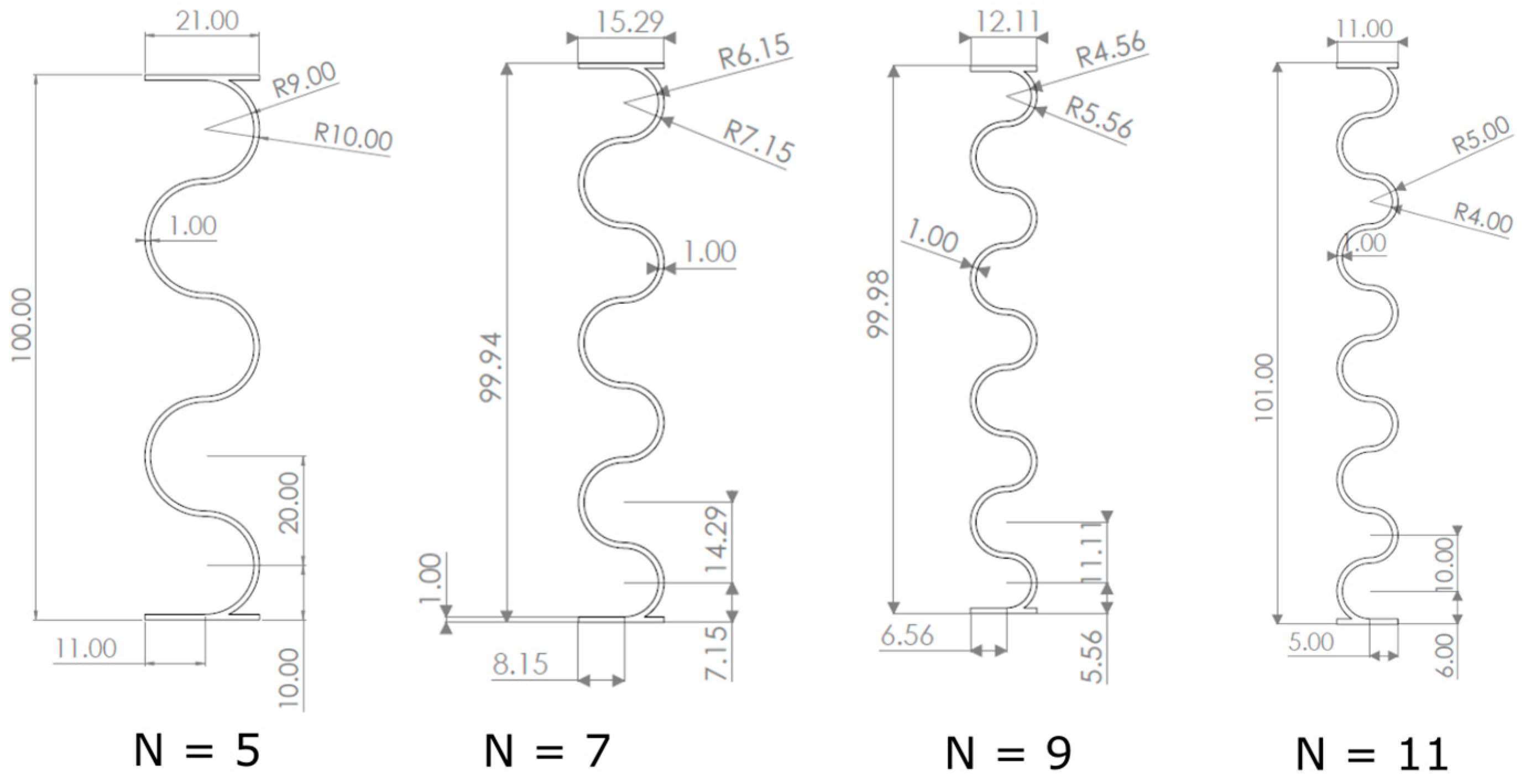
| Number of Spirals (N) | Diameter (cm) | Hight (cm) | Thickness (cm) |
|---|---|---|---|
| 5 | 1.84 | 10 | 0.1 |
| 7 | 1.29 | 10 | 0.1 |
| 9 | 0.97 | 10 | 0.1 |
| 11 | 0.78 | 10 | 0.1 |
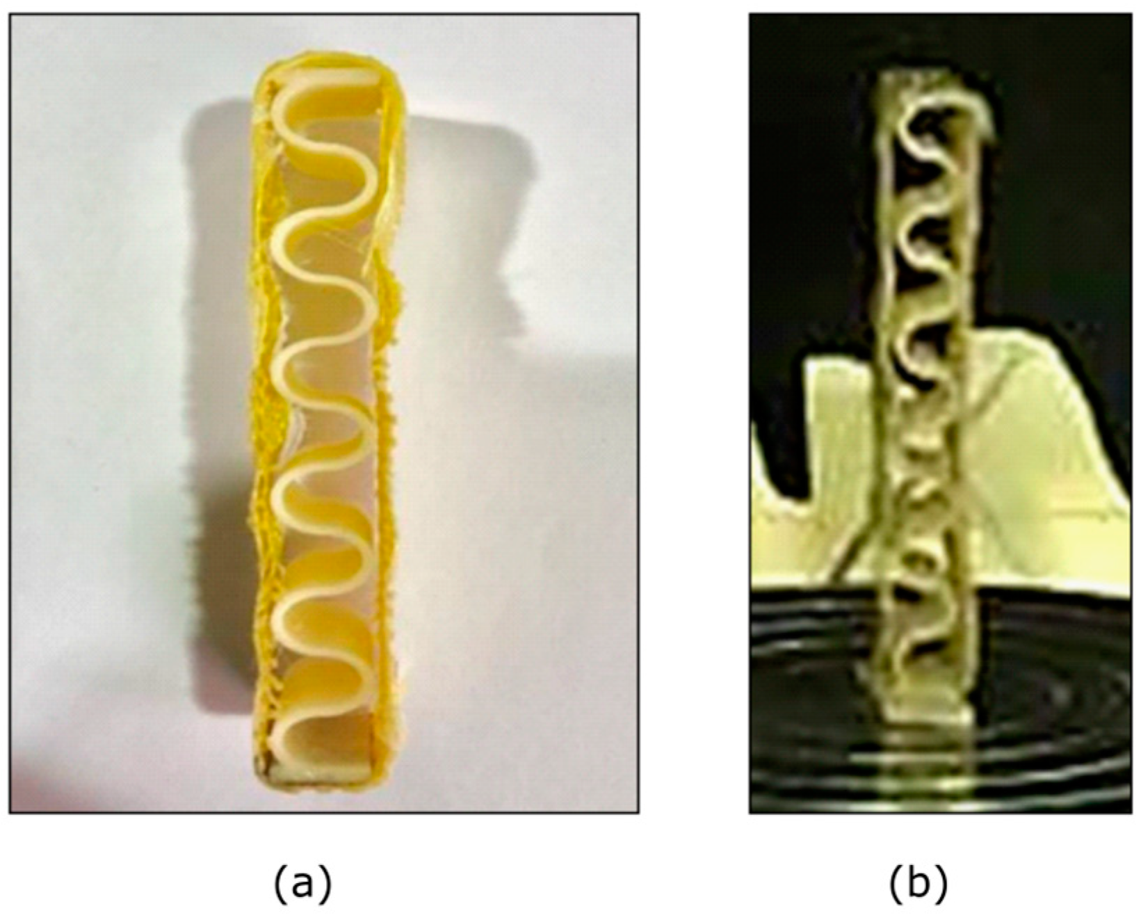
| Material | No. of Spirals | Sample Picture before the Test | Sample Picture after the Test |
|---|---|---|---|
| ABS Plastic | 5 |  |  |
| ABS Plastic | 7 |  |  |
| ABS Plastic | 9 |  |  |
| ABS Plastic | 11 |  |  |
| ABS Plastic and Kevlar Fiber | 5 |  |  |
| ABS Plastic and Kevlar Fiber | 7 |  |  |
| ABS Plastic and Kevlar Fiber | 9 |  |  |
| ABS Plastic and Kevlar Fiber | 11 |  |  |
| ABS Plastic and Foam | 5 |  |  |
| ABS Plastic and Foam | 7 |  |  |
| ABS Plastic and Foam | 9 |  |  |
| ABS Plastic and Foam | 11 |  |  |
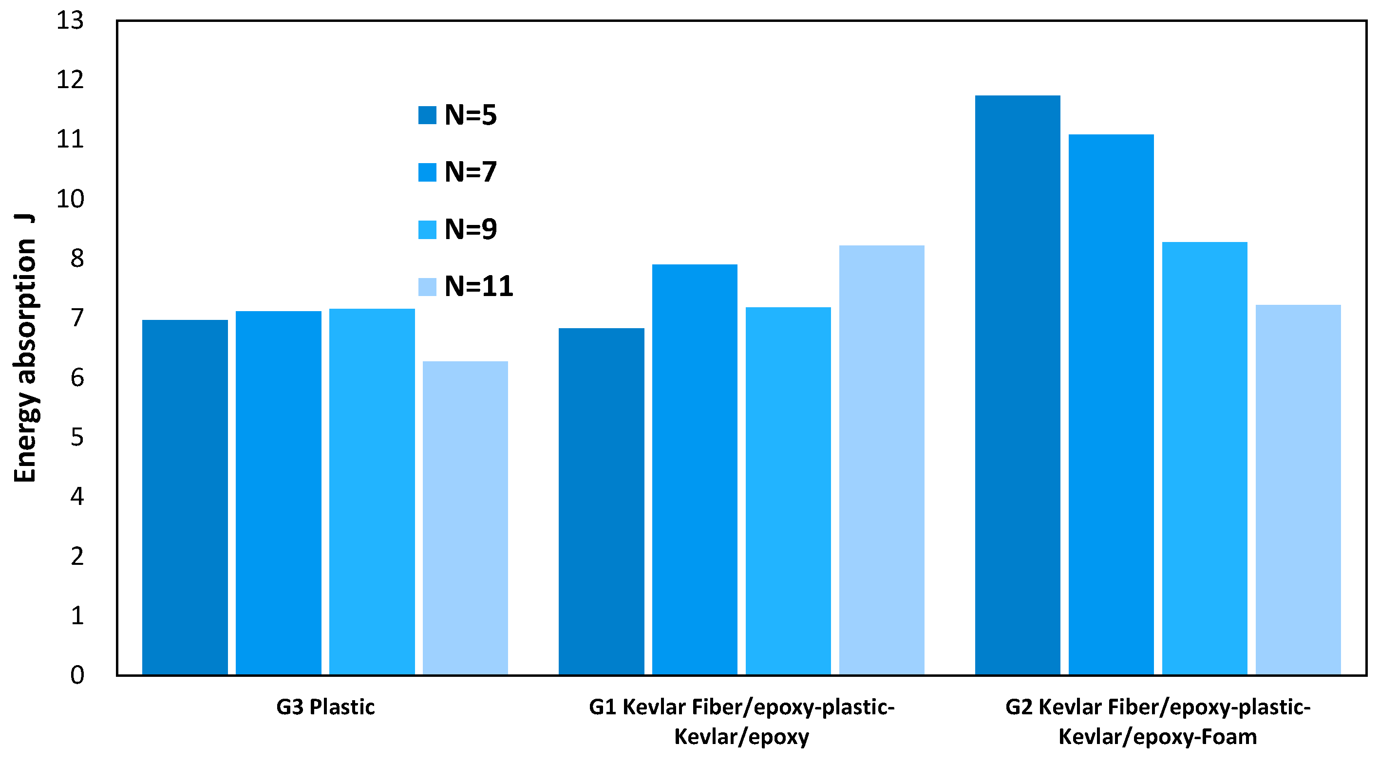
| Number of Spirals | Composition Type | ||
|---|---|---|---|
| Plastic | Kevlar Fiber | Foam | |
| 5 | 7.164 | 6.991 | 11.689 |
| 7 | 7.339 | 8.281 | 10.904 |
| 9 | 7.384 | 4.417 | 8.729 |
| 11 | 6.325 | 8.663 | 7.461 |
| Source of Variability | DF | Sum of Square | Mean Square | F Statistic | p-Value |
|---|---|---|---|---|---|
| Spiral Number | 3 | 8.0370 | 2.679 | 1.064 | 0.4315 |
| Composition Type | 2 | 18.380 | 9.191 | 3.650 | 0.0918 |
| Error | 6 | 15.106 | 2.518 | ||
| Total | 11 | 41.524 | 3.775 |
Disclaimer/Publisher’s Note: The statements, opinions and data contained in all publications are solely those of the individual author(s) and contributor(s) and not of MDPI and/or the editor(s). MDPI and/or the editor(s) disclaim responsibility for any injury to people or property resulting from any ideas, methods, instructions or products referred to in the content. |
© 2023 by the authors. Licensee MDPI, Basel, Switzerland. This article is an open access article distributed under the terms and conditions of the Creative Commons Attribution (CC BY) license (https://creativecommons.org/licenses/by/4.0/).
Share and Cite
Bennbaia, S.; Mahdi, E.; Abdella, G.; Dean, A. Composite Plastic Hybrid for Automotive Front Bumper Beam. J. Compos. Sci. 2023, 7, 162. https://doi.org/10.3390/jcs7040162
Bennbaia S, Mahdi E, Abdella G, Dean A. Composite Plastic Hybrid for Automotive Front Bumper Beam. Journal of Composites Science. 2023; 7(4):162. https://doi.org/10.3390/jcs7040162
Chicago/Turabian StyleBennbaia, Shada, Elsadig Mahdi, Galal Abdella, and Aamir Dean. 2023. "Composite Plastic Hybrid for Automotive Front Bumper Beam" Journal of Composites Science 7, no. 4: 162. https://doi.org/10.3390/jcs7040162