Article

Smart Composite Booms for Solar Sails

1
Department of Industrial Engineering, University of Rome “Tor Vergata”, Via del Politecnico 1, 00133 Rome, Italy
2
Department of Astronautical Electrical and Energy Engineering, Sapienza University of Rome, Via Salaria 851, 00138 Rome, Italy
3
Italian Space Agency, Via del Politecnico s.n.c., 00133 Rome, Italy
*
Author to whom correspondence should be addressed.
J. Compos. Sci. 2023, 7(12), 495; https://doi.org/10.3390/jcs7120495
Submission received: 29 September 2023 / Revised: 2 November 2023 / Accepted: 13 November 2023 / Published: 30 November 2023
(This article belongs to the Topic Advanced Carbon Fiber Reinforced Composite Materials)

Abstract

:
Composite booms for solar sails have been prototyped by using innovative smart materials. Shape memory polymer composites (SMPCs) have been manufactured by interposing SMP layers between carbon-fiber-reinforced (CFR) plies. A polyimide membrane has been embedded into the CFR-SMPC frame of the sail during lamination. The sail’s size has been limited to 250 × 250 mm2 to allow its testing on Earth. The feasibility of large sail deployments has been shown by prototyping small CFR-SMPC elements to insert only in the folding zones. Numerical simulation by finite element modeling allowed for predicting the presence of wrinkles close to the frame’s vertexes in the cases of large sails under solar radiation pressures. Nevertheless, the frame’s configuration, with SMPC booms at all the edges of the sail membrane, seems to be suitable for drag sails instead of propulsion. On-Earth recovery tests have been performed on 180° folded sails by using flexible heaters. After an initial induction time, the maximum rate was reached with a following drop. In the case of two heaters per folding zone, the angular recovery rate reached the maximum value of about 30 deg/s at the power of 34 W, and full recovery was made in 20 s.

1. Introduction

The increasing interest towards deep space exploration has led to investigations of new propulsion systems, which would be suitable for long-term missions, thus minimizing structure aging and resource consumption. The state-of-the-art propulsion systems are mainly based on propellants that supply the required energy for any mission need of space structures, such as thrust and attitude maneuvers. A different and very promising propulsion system is offered by solar (or photonic) sails, which derive their energy from solar radiation pressure (SRP). The choice of new suitable materials for unmanned aerial vehicles (UAVs) is a critical aspect which must be carefully considered [1]. The feasibility of solar sail technology was successfully demonstrated in 2010 by the Japanese Space Agency (JAXA) thanks to the space probe Interplanetary Kite-craft Accelerated by Radiation Of the Sun (IKAROS) that was driven up to Venus after the sail’s deployment [2]. The IKAROS sail membrane had a thickness of 7.5 µm and a square shape, with a side of 20 m, divided into four trapezoidal subelements. Its deployment and flatness were ensured through centrifugal forces, generated by the payload spinning, thanks to the presence of small masses at the square vertices.
IKAROS is still the most successful experiment of solar sail deployment and its use in a space environment. However, other solar sail prototypes have been proposed by other space agencies, the tests of which have been mainly carried out on Earth. In particular, two square solar sails, with the same size of IKAROS, were produced by NASA (Washington, DC, USA) and successfully tested under vacuum [3]. In these sails, a new architecture is introduced with a central body structure, from which four deployable booms start, one for each semi-diagonal square. In the end of the deployment, the rigid deployed structure is responsible for the membrane’s flatness, and spinning is avoided. A lack of funding caused NASA to develop two subscale solar sails, namely, NanoSail-D and NanoSail-D2 [4]. Only NanoSail-D2 completely deployed on orbit, in January 2011.
In the same year as the NanoSail-D2 mission, the Surrey Space Centre (UK) introduced the concept of bi-stable booms. Booms have two stable configurations, one coiled and one extended, like a tape spring. In a lab-scale prototype, the sail membrane was divided into strips, and each strip was tensioned between adjacent bi-stable booms [5]. This deploying strategy has also been adopted by the German Aerospace Center (DLR) for its Gossamer program. In the Gossamer-1 project, light-weight coilable booms were manufactured with a carbon-fiber-reinforced polymer (CFRP) and were arranged in a cross-like layout. The section of the booms consisted of two half shells, each one with an omega cross-section, to reach the necessary stiffness without reducing the ability to be coiled. In analogy with IKAROS, the sail membrane was 7.5 µm thick, made in polyimide, and coated on both sides with 100 nm vacuum-deposited aluminum [6]. Gossamer-1 aimed at developing a low-cost demonstrator for membrane deployment with a 5 × 5 m2 sail for very low Earth orbit (LEO). Moreover, it had to evolve in Gossamer-2 and Gossamer-3. The former dealt with the validation of all the related technologies on a 20 × 20 m2 sail in Earth’s orbit, where photonic pressure becomes dominant. The latter deals with a fully functional 50 × 50 m2 solar sail to validate the design approach and prove its reliability to conduct space weather missions [7]. However, the rise of several issues limited the achievements of Gossamer-1 to the system’s hardware and the deployment’s technology qualification. Separable deployment units were used [8].
The main challenge in the design and development of a solar sail is its size, as very large and very light structures are necessary after deployment. These light structures are difficult to test on Earth because of its gravity. Nevertheless, for experimentation in a space environment, small structures are preferred. They also give the further advantage of a possible application as drag sail, instead of propulsion. In fact, small satellites in LEO may reduce their permanence in orbit at their end of life thanks to the drag effect of the small, deployed sail. An example is SiaSail-I, which was based on a 6U cubesat [9]. The bi-stable composite booms were used again and constituted a second-stage deployment mechanism. After a 10-year research program, the LightSail-2 mission included a sail with a surface area of 32 m2 after full deployment in orbit [10]. In this case, the membrane was made of four independent triangular aluminized Mylar® sheets, 4.6 µm thick. The sail segments were deployed by four triangular retractable and collapsible booms, made of a non-magnetic and non-corrosive alloy. In the InflateSail mission, a 3U cubesat was equipped with a 1 m long inflatable mast and a 10 m2 deployable drag sail [11]. The sail membrane was a 12 µm thick polyethylene naphthalate (PEN) film, divided into quadrants and left un-metallized to minimize perturbation from SRP. In analogy with most of the previous experiments in space, apart from IKAROS, the sail structure consisted of four bi-stable booms made of CFRP and coiled just above the wrapped sail’s membrane.
The selection of a deployment architecture has several impacts on deployable strategies [12] and manufacturing constraints. The body sail is a large ultra-thin membrane and is metallized; therefore, wrinkles may occur due to folding, thus limiting the propulsion efficiency. When designing, these wrinkles can be predicted in small and large sails [13] by finite element modeling (FEM). The goal is minimizing the payload volume before launch and avoiding boom failure and sail tearing after in-orbit deployment. The origami-based concept offers suitable solutions to implement packing strategies [14]. More recent trends are developing self-folding membranes by using space-qualified materials that deploy upon solar irradiation [15]. However, finding the optimal configuration is a difficult task, and manufacturing issues are often neglected. Additional loads may arise during the deployment process [16] that negatively affect the membrane deformation. At present, CFRP booms are strongly supported because of the low weight and well-consolidated manufacturing processes [17]. The bi-stable configurations are the most used with the further advantage of a direct joining of the body sail under different geometrical constraints [3,18]. Also in this case, numerical modeling is a very powerful mean to predict stress and strains arising during wrapping and deploying, by using CFRP booms [19,20]. Results have led to optimization of the boom geometry as in the case of four-cell lenticular honeycomb booms [21] or N-shaped composite ultra-thin booms [22].
Despite of the huge amount of work on solar sail structures, the concept of a deploying system has remained more or less the same after IKAROS, with bi-stable deploying booms. A recent innovation in smart CFRP materials has changed this concept thanks to the adoption of shape memory polymer composites (SMPCs). They combine the structural properties of CFR laminates with the functionalities of shape memory polymers (SMPs). In analogy with SMPs, SMPCs are able to temporarily fix a deformed configuration after a thermomechanical cycle and to recover the initial equilibrium configuration by means of an external stimulus, mainly heating, in the absence of constraints. In composite laminate, shape memory (SM) properties depend upon the polymeric matrix whereas the reinforcements are responsible for the mechanical performances. These materials have been proposed for aerospace applications such as deploying hinges, solar arrays, reflector antennas, deployable panels, and booms [23], as well as a cubic deployable support structures [24].
In recent developments, CFR-SMPCs have been manufactured by laminating commercial CFR prepregs with SMP interlayers [25]. An optimal adhesion among CFR plies and an SMP epoxy resin is obtained thanks to a co-curing compression molding process [25]. The same SMP resin of the current study was previously tested, under microgravity, in the form of foams and interlayers of a CFR laminate [26]. Recently, an autonomous CFR-SMPC device has been designed and manufactured by inserting an embedded heater into the composite laminate [27]. Several memory-recovery tests have been performed to test the durability of the SMPC architecture with optimal results [25,27]. These results show that SMPC booms can be very promising for solar sail structures thanks to the ability of storing different shapes in the absence of loads. In the current study, a small square prototype of the smart sail with SMPC booms is proposed. The aim of the study is mainly related to the need for performing the first step toward a future application of this very innovative deploying architecture. In particular, manufacturing issues have been analyzed before design constraints. As a result, a 250 × 250 mm2 sail has been prototyped, more similar to the structure of a drag sail than a solar sail, but the feasibility of increasing the sail size up to 39 × 39 m2 is discussed. The idea is adopting this deploying architecture for missions such as Helianthus, where the solar sail would be necessary to maintain an equilibrium point in the Sun–Earth gravitational field [28].

2. Materials and Methods

The research activities have been carried out to manufacture a small sail structure, to be tested on Earth, but numerical modeling has been applied to the case of large sails for solar propulsion. In terms of materials and sizes, the final prototype is more similar to a drag sail for low Earth orbit (LEO). In fact, the membrane is made of a 50 µm polyimide film, much thicker than typical thin membranes of solar sails, and not aluminized. The booms are made of CFR-SMPCs and are placed on the external perimeter of the square membrane, embedding its edges. This architecture is referred to as “frame configuration” (Figure 1) because of the presence of a continuous SMPC frame around the membrane. The SMPC booms have been obtained by manual lamination of CFR prepregs with an SMP interlayer (nominally 100 µm thick) and compression molding.

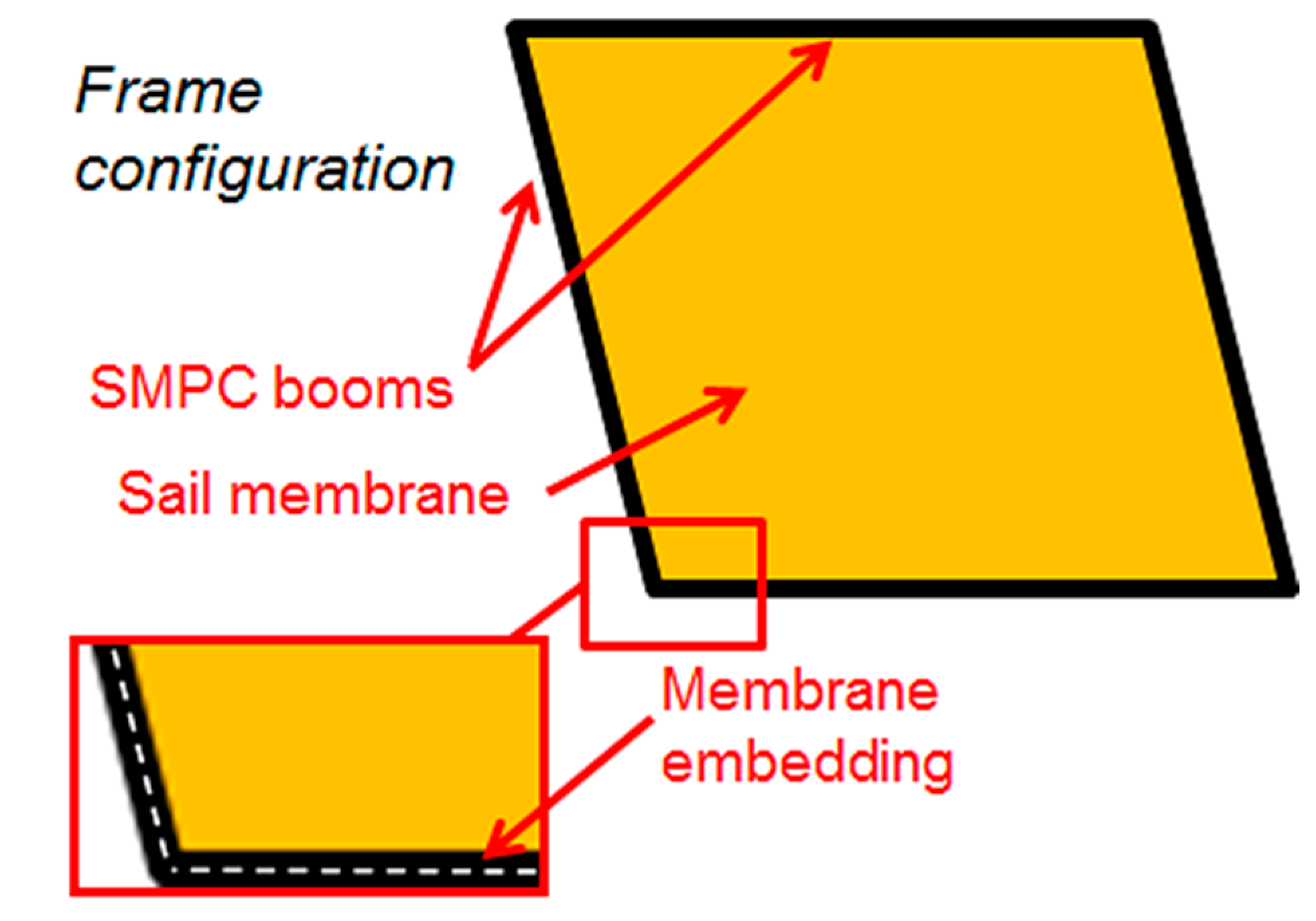
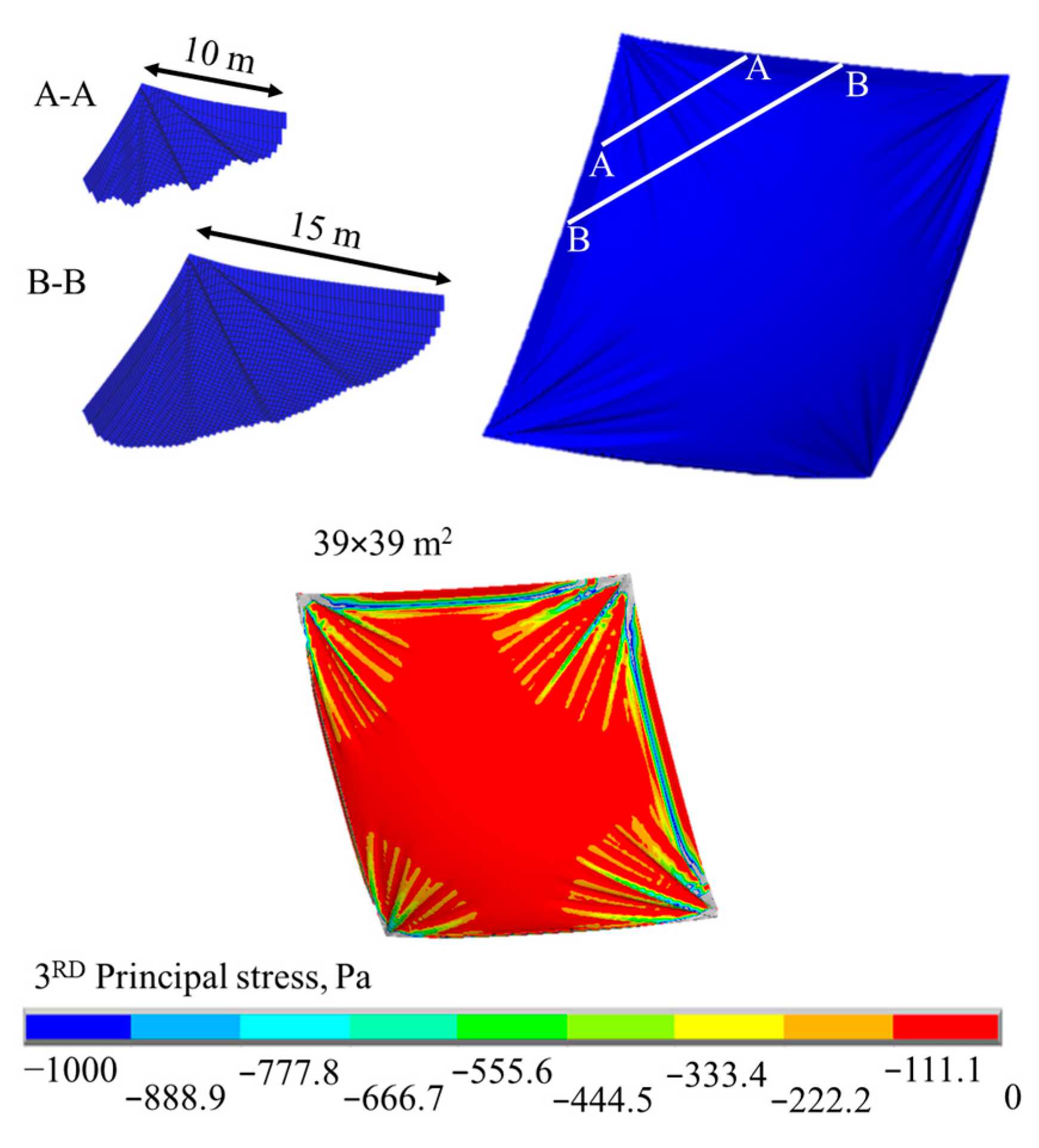
2.1. Numerical Modeling

Numerical design and modeling have led to investigation of the sail behavior in operation or, at least, under reference loads. In particular, for SMPC booms, the deployment of large sails cannot be tested on Earth as gravity loads are comparable to or higher than SMPC recovery loads. Therefore, validation of numerical models was carried out by using small prototypes. A finite element model of the deployed sail has been implemented in an ANSYS 18.0 environment with a batch approach, through the ANSYS parametric design language. As shown in Figure 2, the model geometry consists of a thin square membrane and a narrow stripe along the perimeter of the membrane itself, representing the SMPC frame. According to the requirements from the Helianthus mission, the square membrane has an edge of 39 m [28]. In fact, the area of the sail to provide optimal flight dynamics and attitude control should range between 1300 m2 and 1500 m2. For the finite element (FE) model, the SMPC thickness was fixed at 1 mm whereas the membrane thickness was 7 µm, close to commercially available polyimide films for space use.
In Figure 2, the FE model and mesh of the sail are shown together with the applied loading conditions. The membrane is mapped meshed with Shell 181 elements whereas the SMPC frame is meshed with Beam 188 elements. The edges of the membrane and the frame have the same nodes; therefore coupling is used. The number of divisions was set to 120 × 120 for a sum of about 14,400 elements. Due to this mesh density, the computational time was reduced to about 30 min.
Elastic properties of the sail membrane and the SMPC booms are summarized in Table 1.
The numerical convergence of the proposed model is a complex task due to several issues. The first is the difference between the sail thickness (0.007 mm) and the sail side (39,000 mm). Moreover, the stiffness of the whole structure is very low and thus very sensitive to such loading conditions. These issues were responsible for numerical instabilities which have been overcome by using the non-linear solution approach. In this case, the stiffness matrix is updated at each single iterative step, starting from the structure deformation of the previous solution step.
For simulation, the displacements of the sail vertexes were constrained as well as the rotation around the axis normal to the membrane plane. The solar radiation pressure of 4.5 µPa, acting on the full membrane area, was the only applied load. The SRP was converted into nodal loads that preserved their orientation independently from each single iterative step. This approach better represents the real behavior of the photonic pressure, different from the mechanical pressure that is always perpendicular to the surface where it acts.

2.2. Manufacturing and Testing

In the manufacturing of a large solar sail with the frame configuration (Figure 1), SMPC laminates can be positioned only in the folding zones whereas traditional CFR stripes can be used for passive parts of the frame. In the manufacturing of small prototypes, instead, the application of the SMP interlayer to the whole frame can be easier than using SMPC hinges, thus eliminating the joints between the hinges and the passive elements. In the current study, both configurations have been considered, and flexible heaters have been embedded into the autonomous smart structures.

2.2.1. Raw Materials and Suppliers

Commercially available materials were used to produce all the SMPC structures. The CFR prepreg was M49/42%/200-PW CCF-3k by Hexcel (Stamford, CT, USA), commonly used for high-performance structures in aeronautics. This is a 0/90 carbon fiber (CF) fabric-reinforced prepreg with thermosetting epoxy matrix. This cured epoxy resin does not have remarkable SM properties; therefore, an SMP interlayer was added during lamination. This interlayer was acquired in the form of an un-cured epoxy powder, namely, Scotchkote 206N by 3M (Maplewood, NJ, USA). During manufacturing, the un-cured epoxy powder was placed between adjacent CFR prepreg stripes to obtain an SMP interlayer with a nominal thickness of 100 µm. Previous works have already discussed the good SM performances of this SMP resin in the form of foam or in the form of CFR laminate interlayers [25,26,27].
The membrane of the sail prototype was made with a 50 µm thick polyimide film (Kapton HN) by Dupont®. This material can withstand temperatures up to 400 °C without melting or degrading and it is already used for several space applications.
The flexible KHLVA-0502/10 heater by Omega (Stamford, CT, USA) had a rectangular shape and consisted of an Inconel etched circuit (25.4 µm thick) encapsulated between two polyimide layers (50.8 µm thick). According to its datasheet, this heater has a resistance of 80 Ω and can be supplied with a nominal voltage up to 28 V. It has been successfully used to build an autonomous SMPC actuator [27], thanks to its low thickness and flexibility.

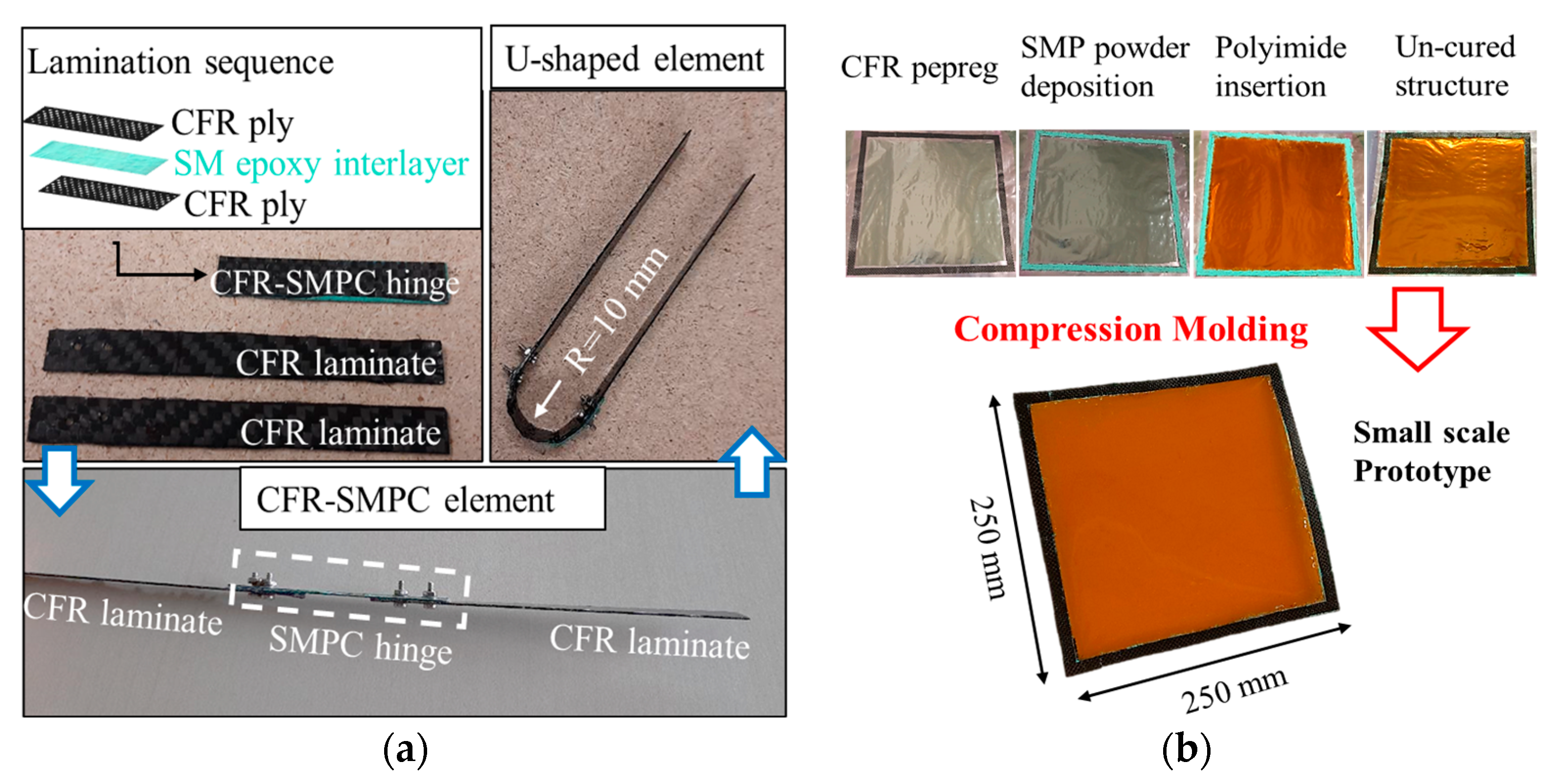
2.2.2. Molding of SMPC Structures

SMPC booms have been produced following the procedure of Figure 3. The SMPC hinge (Figure 3a) and the small sail (Figure 3b) were both hand-laminated by interposing an SMP interlayer, being initially in the shape of free un-cured powder and subsequently co-cured under compression molding. The idea is that a large sail is manufactured by using SMPC hinges as there is no advantage in having the SMP interlayer in zones where folding is not necessary. On the other side, small prototypes of sails with SMPC hinges are complex to manufacture. Moreover, mechanical joints, between the hinges and the passive CFR elements, lead to higher weights and interference issues during folding. In this study, the goal was to manufacture a sail that could be deployed on Earth (Figure 3b) but also showing technical solutions to be adopted for large sails (Figure 3a).
All the composite laminates, SMPC and passive, were two ply. For lamination, prepreg stripes with a size of 10 × 60 mm2 were cut for the SMPC hinge and 10 × 250 mm2 for the passive elements. In the case of the sail, the whole frame of 250 × 250 mm2, and with a width of 10 mm, was cut from the prepreg roll. In the lamination sequence, a prepreg ply was placed on a release film, and the un-cured SMP powder was poured on it. For the sail, a polyimide square membrane, with a side of 240 mm, was positioned in the center of the SMP layer. Subsequently, for both structures, the top CFR prepreg was placed and a second release film on it. Laminate consolidation was carried out by compression molding at low pressure (50 kPa) with a temperature of 200 °C for 1 h.
At the end of manufacturing of the prototype of the CFR-SMPC solar sail element (Figure 3a), the SMPC hinge had an average thickness of 910 µm, and that of the passive CFR laminate was 770 µm. By these values, the thickness of 140 µm can be inferred for the SMP interlayer. The active and passive parts of the smart element were joined through bolts with a diameter of 2 mm.
The small sail (Figure 3b) had an average thickness of 800 µm, smaller than the SMPC hinge, despite the presence of the polyimide membrane (50 µm thick). In fact, more resin bleeding was produced at the interface between this membrane and the SMP interlayer. The sail prototype had a mass of 13.8 g, 70% of which was related to the CFR-SMPC frame. The presence of residual stresses from the laminate cure was responsible for the small distortion of the sail that is visible in Figure 3b.

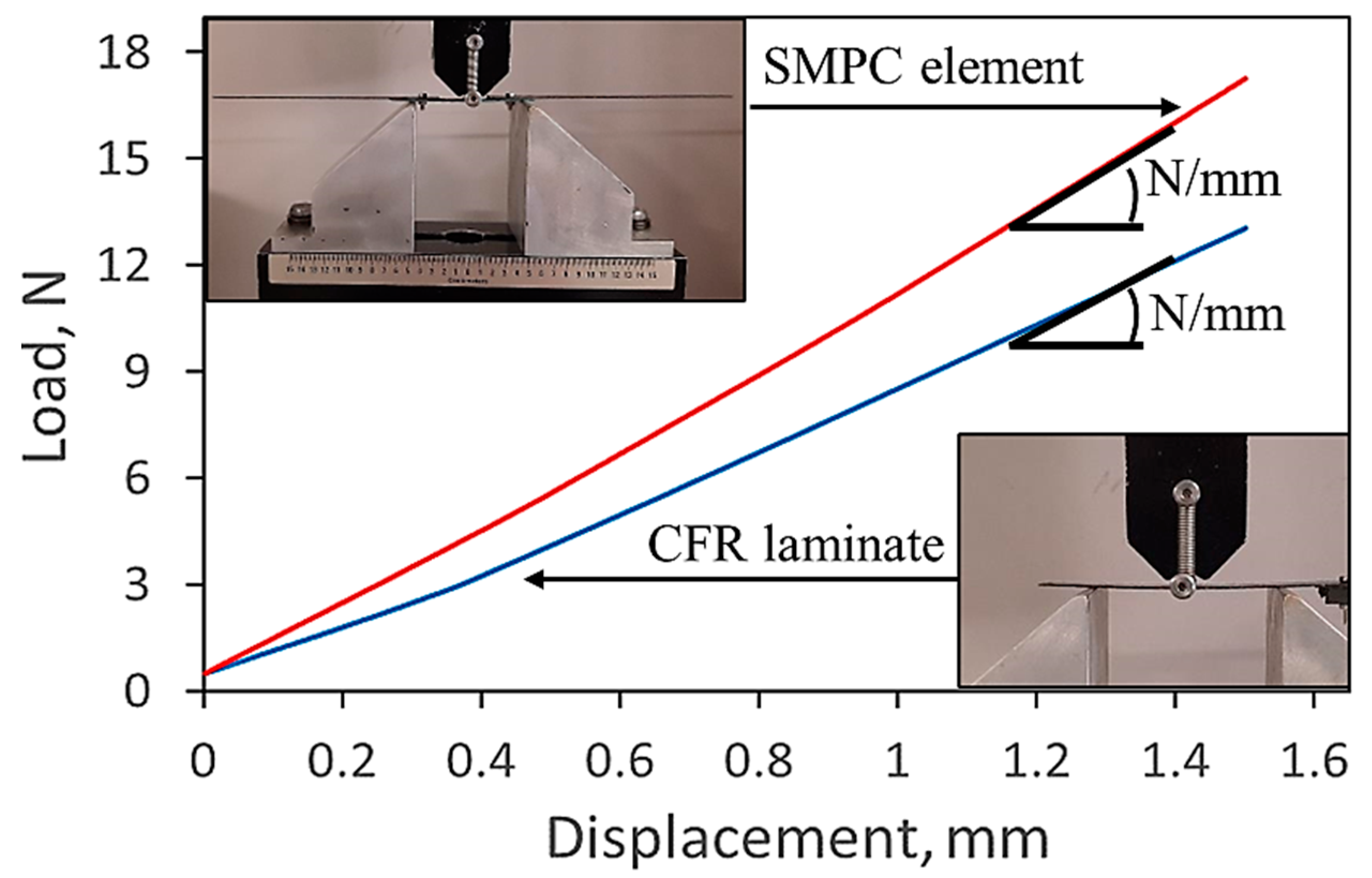
2.2.3. Mechanical Testing

Mechanical behavior of the active and passive laminates of the hinge was measured by bending tests through an MTS Insight 5 universal material testing machine (Eden Prairie, MN, USA). Tests were carried out in three-point bending configuration, at the rate of 1 mm/min and with the span length of 45 mm.

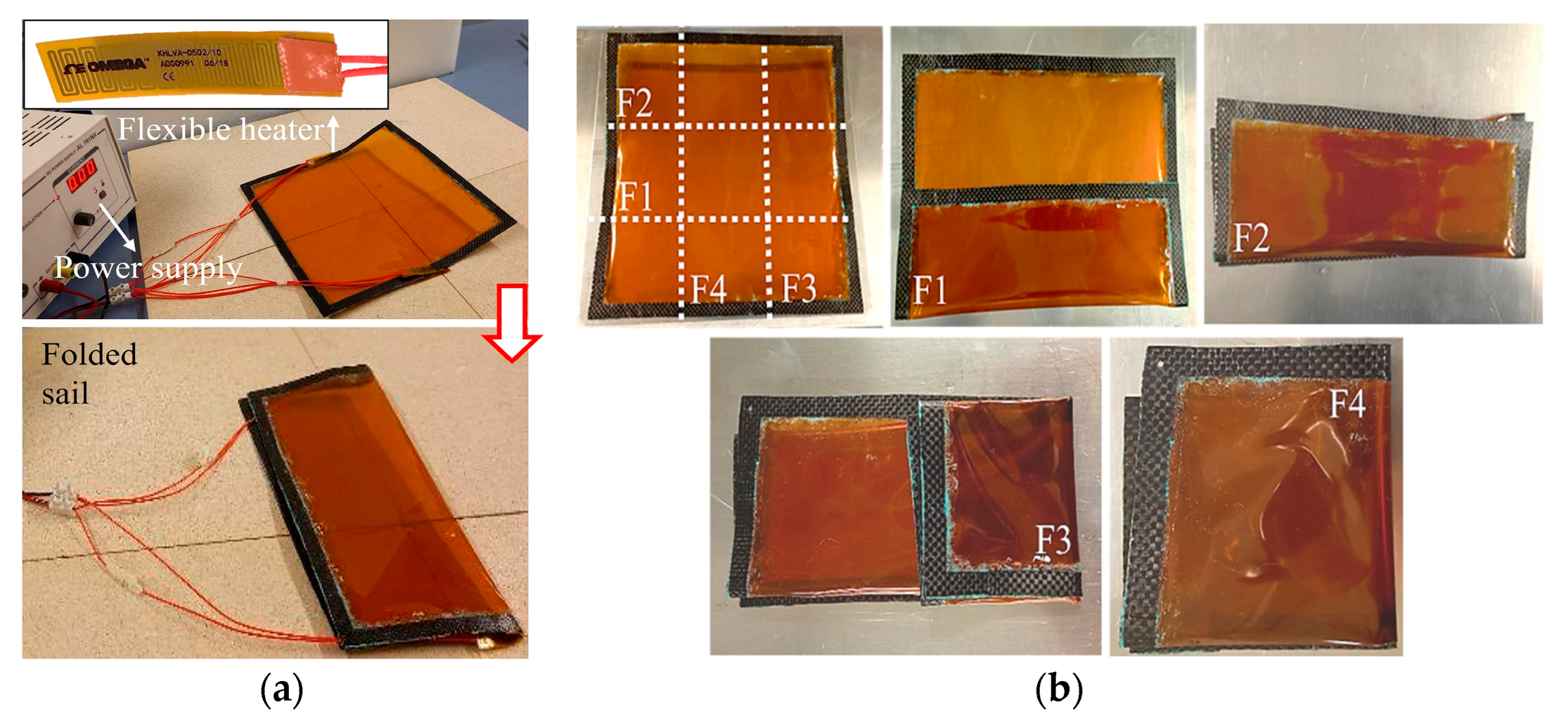
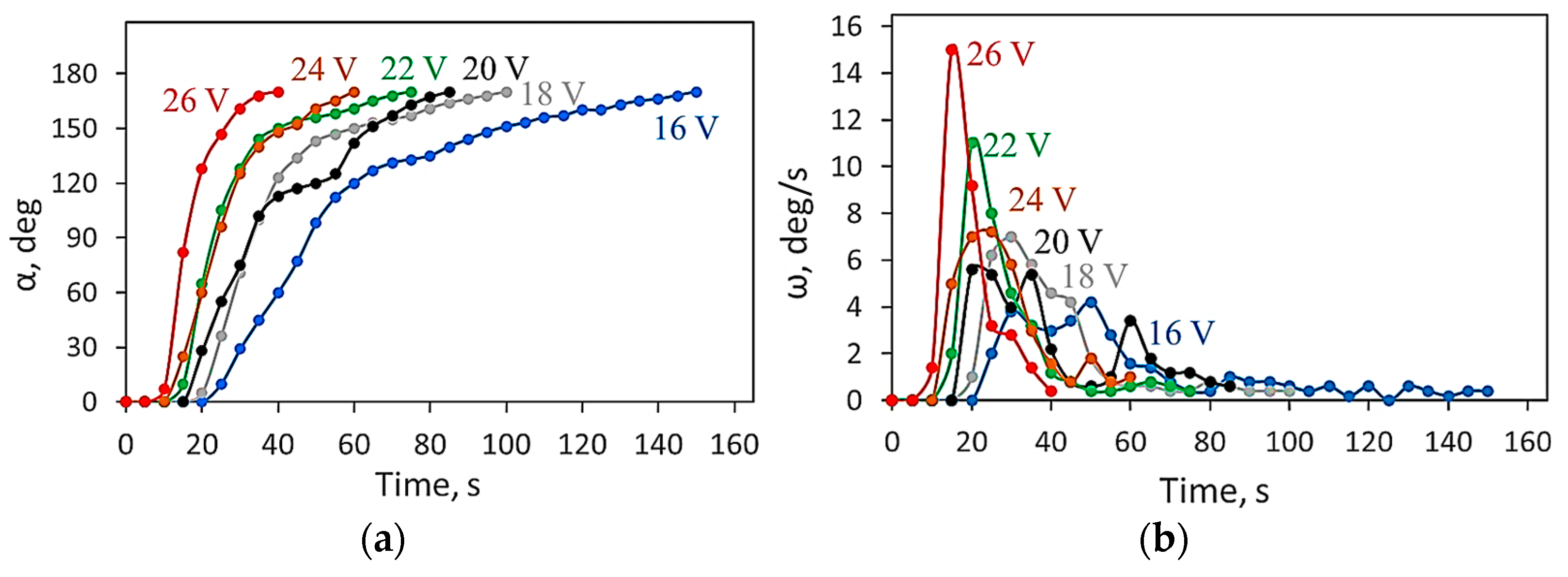
2.2.4. Shape Memory Testing

For thermoset SMPs and SMPCs, the trigger temperature for the shape change is the glass transition temperature. At this temperature, the molecular mobility of the SMP is high, therefore it can withstand large deformations without damage. During cooling, SMPs have the ability to freeze most of the applied deformation. After cooling, the temporary shape becomes stable but, if heating is still applied over the glass transition, the same molecular mobility leads to recovery of the initial equilibrium configuration. In the current study, the heat required for SMPC transition was supplied in three different methods: by local flexible heaters and irradiation for the sail, and by a hot air gun for the SMPC sail element. The heating source was changed only to simplify the testing procedures. In fact, for a single folding zone of the sail, flexible heaters were used (Figure 4a), but for multiple folding zones (Figure 4b) recovery in an oven was preferred. The increase in the number of folding points leads to an excessive weight of heaters and cables, and the sail deployment could be prevented.
In the case of a multi-folded sail (Figure 4b), the structure size reduced to 85 × 85 mm2 (about 12% of the initial size). At each folding point, the SMPC boom undergoes a 180° angular deformation with a curvature radius ranging from 2 to 4 mm. For a large sail, more folding operations would be necessary and a CFR-SMPC element could be placed at each folding point. In the case of Figure 3a, a curvature radius of 10 mm was applied.
The single folding configuration (Figure 4a) was used to measure the recovery rate under heating, by placing one flexible heater at the extrados of the deformed booms or two heaters on both sides of the SMPC laminates. In order to evaluate the thermal gradient across the SMPC laminate during heating, the temperature has been recorded on the top and the bottom of the SMPC laminate by 2 K-type thermocouples, according to Figure 5. In the case of the top of the laminate, the thermocouple was inserted between the heater and the SMPC surface; therefore, the recorded values were higher and a gradient over 100 °C was measured at the maximum voltage of 26 V (Figure 5). After the heater turns off, temperatures rapidly reduce and, in less than one minute, the gradient disappears. In Figure 6a,b, the temperature acquisitions on the top and bottom surface of the SMPC laminate, respectively, are shown as a function of the applied voltage (ranging from 16 to 26 V with 2 V steps). The highest voltage was limited to 26 V to prevent degradation of the heater. At voltages lower than 16 V, the resulting temperatures are too low to overcome the glass transition of the SMP epoxy resin and the CFR-ply epoxy matrix. The evolution of the curves of Figure 5 and Figure 6 shows that a time of about 2 min is always necessary to reach a plateau value of the temperature for all the voltages, but the temperature gradient partially decreases when decreasing the voltage.
For instrumented recovery tests, the small sail was folded in two halves, as in Figure 4a, and its recovery was recorded over time with the same voltages of Figure 6. From the acquired images, the recovery angle has been extracted and the deploying angular speed extracted.

3. Results

3.1. Numerical Modeling

The proposed FE model is able to predict some important behaviors and occurrences of the sail when in operation. In Figure 7, the displacement normal to the undeformed membrane and the arising von Mises stress are shown. The maximum normal displacement is 35 mm, in the center of the membrane, whereas the maximum displacement of the booms is only 5.2 mm (about 15% of the maximum displacement). As expected, maximum stresses arise close to the constraints (about 100 kPa), therefore they are dependent on the selected configuration. On average, the resulting von Mises stress is only about 10 kPa.
The most interesting result from numerical simulation is related to the prediction of the wrinkling zones, that are highlighted in Figure 8 by the deformed shape of the sail and the map of the minimum principal stress.
These wrinkles arise in the model due to the confinement of the polyimide membrane in the CFR booms. It is interesting to observe that, also in the theoretical case of a perfectly flat deployed sail, wrinkles occur due to the applied solar pressure. They could affect the performances of the propulsion system.

3.2. Mechanical Testing

Results from bending tests of the different parts of the CFR-SMPC element are shown in Figure 9 in terms of loading curves. The stiffness is extracted from the linear stage and is 11.14 ± 0.04 N/mm for the SMPC hinge and 8.82 ± 0.03 N/mm for the passive element. Moreover, stiffness modulus extracted from the same linear stage of the stress–strain curve is 31.5 ± 0.1 GPa for the SMPC hinge and 44.7 ± 0.1 GPa for the passive element. The SMPC stiffness is about 25% higher because of the higher thickness of the two-ply laminate and the consequent longer distance between the CFR plies. After normalization, a maximum stress of 132 MPa for the SMPC laminate was reached (144 MPa for the passive element) without failure. These values are incomparably higher than numerical stresses extracted from numerical simulation (that rarely reach 0.1 MPa). The optimal stiffness of the sail design structure is targeted, and its strength is also not an issue in the case of thin CFR laminates.

3.3. Shape Memory Testing

Shape recovery tests of the solar sail by using flexible heaters (Figure 10a) and irradiation in an oven (Figure 10b) have confirmed the potentiality of SMPCs for deployable structures. The recovery rate depends on the applied heating systems and resulting temperature homogeneity. In this study, fast recovery has been obtained in the case of single folding and multiple heaters, as most of the applied deformation is lost in the first 20 s (Figure 10a). In the case of a multi-folded sail, it has not been possible to insert two heaters for each folding zone.
In Figure 10b, the sail is folded four times, and sixteen heaters would have been necessary for heating, with many issues regarding their insertion in the small available area and an excessive increase in the sail weight. For this reason, the multi-folded sail was tested in an oven, and its recovery was obtained by the irradiation from the hot walls. The recovery rate is limited due to the difficulty of applying high temperatures in a homogeneous way. Moreover, due to gravity, some movements were slowed down and more than seven minutes were necessary for full recovery. The main result to discuss is that damage was not visible on the membrane and in the composite booms at the end of the memory-recovery cycle. In order to guarantee temperature uniformity, the CFR-SMPC hinge was recovered by a hot-air gun unit (Figure 11) and only 80 s were sufficient for full deployment. Hot air is useful to infer the recovery rate in the case of the absence of gravity, as the effect of the weight of the heater is not negligible for these small devices. After camera recording, it was possible to extract the angular change over time of two different free-recovery tests (Figure 12a). The derivative of the angular variation is the angular recovery rate (Figure 12b). After an initial induction time (5 s) the angular rate reaches a maximum of about 12 deg/s between 10 and 15 s, but, after 30 s, the recovery speed strongly reduces. In fact, approaching the equilibrium shape, recovery loads decrease and small resistances become relevant.
Local heating by conduction seems to be more effective for SMPC recovery. The results of Figure 10 are very important to test the proposed manufacturing procedures and to show the feasibility of such design solutions. Nevertheless, these results are mainly qualitative. In this study, for the first time, quantitative values for the recovery rate of the deployable SMPC sail have been acquired and have been discussed. A small sail has been preferred to make testing on Earth possible. For the same reason, only one folding zone has been applied to the sail for quantitative evaluations. These results are shown in Figure 13 for one heater, placed at the SMPC extrados, in terms of angular variation (Figure 13a) and angular recovery rate (Figure 13b) as a function of the applied voltage. The angular movement over time (Figure 13a) has the same shape for the CFR-SMPC element with an initial induction time, an inflection point (at the maximum rate), and a final plateau. By increasing the voltage, the initial induction time reduces, and the final plateau is reached in less time. Some oscillations occur because of possible obstacles or unexpected friction upon recovery but, generally, the effect of the 2 V step change is always evident. The maximum rate (Figure 13b) of 15 deg/s was observed at the highest applied voltage (26 V) whereas the rate was always lower than 4 deg/s at the minimum voltage (16 V).
In Figure 14, the recovery angle (Figure 14a) and the angular recovery speed (Figure 14b) are shown for the case of one and two heaters per folding zone (one on each side of the SMPC laminate) at the maximum applied voltage. The single heater consumption is 8.5 W at 26 V; therefore a power of 17 W is necessary for deploying the sail with one heater per hinge, 34 W for two heaters. For multi-folded sails, this power would be applied only for each deploying step. At the highest power, the maximum angular recovery speed of about 30 deg/s is reached with full opening in only 20 s, apart from small residual angles.

4. Discussion

The volume of the payload is a fundamental target for any space mission, and the solar sail is a typical object which is difficult to launch into orbit because of its very large size and very low stiffness. The only solution is packing the sail on Earth and deploying it in orbit. At present, the optimal sail architecture and deploying strategy are still matters of technical and scientific discussions, and only a few and partial solutions have been validated, mostly on Earth. In this challenge, SMPCs with CFs can be the necessary innovation to open new designing routes, thanks to the fact they have the structural performances of traditional CFR laminates and the functionalities of SMPs. Moreover, they exhibit low weight, and they are processed with the same manufacturing technologies as composite laminates. Furthermore, new deploying strategies can be defined by using their shape-morphing properties and the smart frame of Figure 1 is already a good example, not replicable with any other material. Numerical modeling allows finding the optimal sizing of active and passive CFR laminates and predicting anomalies during missions such as wrinkles (Figure 8). Despite numerical instabilities due to the sail’s geometrical details, the developed FE model has been able to predict the complex deformation state of the deployed sail under the effect of the SPR, 4.5 µPa (Figure 7). The highest displacement of the sail is visible in the center of the sail membrane where the displacement is 0.009% of the sail edge length.
The steps to design and validate an SMPC solar sail are many due to its novelty and non-conventional behavior. Recovery tests on Earth have to be carried out to support numerical model validation and to quantify the performances of the different configurations. In the meantime, the feasibility of scaling this technology to large sails has to be shown. A first contribution has been given by the small-scale prototype of Figure 10 through which the packing and deploying procedures as well as the integration of autonomous heating systems have been investigated. For the membrane, a polyimide film with a thickness of 50 µm was used during SMPC lamination. Compression molding provided the desired consolidation between CFR plies, SMP interlayers, and the membrane, contemporarily. The flexible heaters were placed on the external surfaces of the SMPCs and were constituted by polyimide film and coated with heating circuits. In the future, these heating circuits could be deposited on the same surface of the embedded membrane to further reduce the sail weight.
For the first time, in this study, recovery tests of a small CFR-SMPC sail have been carried out in a quantitative approach. In all the tests, the sail recovered the equilibrium shape almost completely. In particular, the residual angle was always about 10 deg (approximately 5.5% of the applied deformation). This angle is probably dependent on residual stresses from compression molding of the SMPC frame and, in fact, it appeared after the first memory-recovery cycle and remained constant in following tests.
Results from recovery tests with a single heater per SMPC (Figure 13) show the possibility of tailoring the sail deployment by the applied voltage. A maximum recovery time of 150 s was observed at the minimum applied voltage (16 V) whereas the minimum time of 40 s (73% decrease) corresponded to the maximum voltage (26 V). Doubling the number of heaters (Figure 14a), the recovery time halves. The average angular recovery speed (Table 2) increases by increasing the applied voltage: ranging from 1.1 deg/s to 4.2 deg/s (about four times higher). However, fast recovery speeds are not a requirement for sail deployment, in fact, the membrane could tear during the unfolding step. Moreover, the packed sail should not unfold from all the points contemporarily, and a strict deployment hierarchy should be imposed by supplying a couple of hinges at a time. In this way, the possibility of deploying under the solar heating should be considered only if such hinge deployments can be activated when necessary. The recovery test performed in an oven shows that irradiation can be a source of recovery but also that unfolding cannot be controlled easily (Figure 10b). In this case, shape recovery was obtained in about 4 min because of the low heat input.
Large sails can be prototyped with a CFR-SMPC frame but recovery tests on Earth are not possible because of the gravity forces that oppose the recovery loads and apply an additional deformation. Single parts can be prototyped such as the CFR-SMPC element (Figure 9), which works as an active hinge on the smart sail. Recovery tests (Figure 11) showed the ability of this architecture to nearly completely deploy, apart from the small residual angle. Recovery time and average angular recovery speed were about 70 s and 2.5 deg/s, respectively. The maximum angular recovery speed was 12.3 deg/s. These recovery parameters are comparable with the ones obtained for the sail prototype supplied at 22 V.

5. Conclusions

In this study, a smart sail with SMPC booms has been prototyped to be tested on Earth. For this aim, the size was very small (250 × 250 mm2), not comparable with sails for solar propulsion (up to 40 × 40 m2). In fact, due to gravity, it is not possible to perform free-deploying tests of large SMPC devices on Earth, as the structure weight can overcome the recovery loads. Nevertheless, the design and properties of the prototyped sail are already promising for use as drag sails for debris mitigation. The feasibility of SMPC booms of large sails has been studied by prototyping and testing single CFR-SMPC elements to be used in the folding zones. The most critical aspect for the proposed frame architecture is the rise of warpages which reduce the sail planarity and can limit its reflective efficiency. It is to be discussed if these wrinkles are comparable with those expected by the aluminized membrane folding.
In terms of manufacturing, most relevant results originated from the SMPC co-curing process, and from the use of flexible heaters. Membrane embedding, instead, seems very useful for drag sails but it would be difficult to extend it to large sails. The sail recovery time (70 s) and rate (up to 12 deg/s) can be modulated through the supplied voltage, to avoid tears of the sail membrane. Theoretically, heat from the heaters could be used in combination with solar irradiation during sail deployment. However, having a constant rate during deployments is an issue for SMPC devices. On the other side, a low rate is applied at the beginning and the end of the shape recovery and they do not need any additional control for this target.
In conclusion, many steps are still necessary to validate SMPC booms for solar sail deployment, but some important findings have been reached. The manufacturing technology is robust and scalable to any size, apart from membrane embedding. Raw materials are commercial, and small prototypes can be manufactured for on-Earth experiments. These experiments can be used to implement numerical models able to predict the behavior of the sail in operative conditions.

Author Contributions

Conceptualization, F.Q.; methodology, L.S.; software, F.Q. and L.I.; validation, C.C., E.C. and R.C.P.; formal analysis, F.Q.; investigation, L.I.; resources, F.Q. and L.S.; data curation, F.Q. and L.I.; writing—original draft preparation, F.Q.; writing—review and editing, F.Q. and L.I.; visualization, C.C.; supervision, L.S.; project administration, E.C. and R.C.P.; funding acquisition, F.Q. and L.S. All authors have read and agreed to the published version of the manuscript.

Funding

This work is performed jointly under the Implementing Agreement between the Italian Space Agency and DIAEE—Sapienza University of Rome n. 2019-28-HH.0-CUP n. F84I19001070005 related to R&D activities on solar photonic propulsion. The Implementing Agreement is based on the Framework Agreement between ASI and “La Sapienza” n. 2015-1-Q.0.

Data Availability Statement

The data that support the findings of this study are available upon reasonable request from the authors.

Acknowledgments

The authors are grateful to Fabrizio Betti for the support given in the experimentation.

Conflicts of Interest

The authors have no competing interests to declare. All co-authors have seen and agree with the contents of the manuscript and there is no financial interest to report. Authors certify that the submission is original work and is not under review at any other publication.

References

  1. Karpenko, M.; Stosiak, M.; Daptula, A.; Urbanowiza, K.; Nugaras, J.; Krolczyk, G.; Zak, K. Performance evaluation of extruded polystyrene foam for aerospace engineering applications using frequency analyses. Int. J. Adv. Manuf. Technol. 2023, 126, 5515–5526. [Google Scholar] [CrossRef]
  2. Tsuda, Y.; Mori, O.; Funase, R.; Sawada, H.; Yamamoto, T.; Saiki, T.; Endo, T.; Yonekura, K.; Hoshino, H.; Kawaguchi, J. Achievement of IKAROS-Japanese deep space solar sail demonstration mission. Acta Astronaut. 2013, 82, 183–188. [Google Scholar] [CrossRef]
  3. Johnson, L.; Young, R.; Montgomery, E.; Alhorn, D. Status of solar sail technology within NASA. Adv. Space Res. 2011, 48, 1687–1694. [Google Scholar] [CrossRef]
  4. Fu, B.; Sperber, E.; Eke, F. Solar sail technology-A state of the art review. Prog. Aerosp. Sci. 2016, 86, 1–19. [Google Scholar] [CrossRef]
  5. Fernandez, J.M.; Lappas, V.J.; Daton-Lovett, A.J. Completely stripped solar sail concept using bi-stable reeled composite booms. Acta Astronaut. 2011, 69, 78–85. [Google Scholar] [CrossRef]
  6. Seefeldt, P.; Spietz, P.; Sproewitz, T.; Thimo Grundmann, J.; Hillebrandt, M.; Hobbie, C.; Ruffer, M.; Straubel, M.; To´th, N.; Zander, M. Gossamer-1: Mission concept and technology for a controlled deployment of gossamer spacecraft. Adv. Space Res. 2017, 59, 434–456. [Google Scholar] [CrossRef]
  7. Grundmann, J.T.; Bauer, W.; Biele, J.; Boden, R.; Ceriotti, M.; Cordero, F.; Dachwald, B.; Dumont, E.; Grimm, C.D.; Herčík, D.; et al. Capabilities of GOSSAMER-1 derived small spacecraft solar sails carrying MASCOT-derived nanolanders for in-situ surveying of NEAs. Acta Astronaut. 2019, 156, 330–362. [Google Scholar] [CrossRef]
  8. Spietz, P.; Spröwitz, T.; Seefeldt, P.; Grundmann, J.T.; Jahnke, R.; Mikschl, T.; Mikulz, E.; Montenegro, S.; Reershemius, S.; Renger, T.; et al. Paths not taken–The GOSSAMER roadmap’s other options. Adv. Space Res. 2021, 67, 2912–2956. [Google Scholar] [CrossRef]
  9. Liu, J.; Zhao, P.; Wu, C.; Chen, K.; Ren, W.; Liu, L.; Tang, Y.; Ji, C.; Sang, X. SIASAIL-I solar sail: From system design to on-orbit demonstration mission. Acta Astronaut. 2022, 192, 133–142. [Google Scholar] [CrossRef]
  10. Spencer, D.A.; Betts, B.; Bellardo, J.M.; Diaz, A.; Plante, B.; Mansell, J.R. The LightSail 2 solar sailing technology demonstration. Adv. Space Res. 2021, 67, 2878–2889. [Google Scholar] [CrossRef]
  11. Underwood, C.; Viquerat, A.; Schenk, M.; Taylor, B.; Massimiani, C.; Duke, R.; Stewart, B.; Fellowes, S.; Bridges, C.; Aglietti, G.; et al. InflateSail de-orbit flight demonstration results and follow-on drag-sail applications. Acta Astronaut. 2019, 162, 344–358. [Google Scholar] [CrossRef]
  12. Zhang, X.; Nie, R.; Chen, Y.; He, B. Deployable structures: Structural design and static/dynamic analysis. J. Elast. 2021, 146, 199–235. [Google Scholar] [CrossRef]
  13. Zou, J.; Li, D.; Wang, J.; Yu, Y. Experimental study of measuring the wrinkle of solar sails. Aerospace 2022, 9, 289. [Google Scholar] [CrossRef]
  14. Dang, X.; Feng, F.; Plucinsky, P.; James, R.D.; Duan, H.; Wang, J. Inverse design of deployable origami structures that approximate a general surface. Int. J. Solids Struct. 2022, 234–235, 111224. [Google Scholar] [CrossRef]
  15. Wu, R.; Roberts, P.C.E.; Lyu, S.; Soutis, C.; Zheng, F.; Diver, C.; Gresil, M.; Blaker, J.J. Rigidisation of deployable space polymer membranes by heat-activated self-folding. Smart Mater. Struct. 2018, 27, 105037. [Google Scholar] [CrossRef]
  16. Seefeldt, P. A stowing and deployment strategy for large membrane space systems on the example of Gossamer-1. Adv. Space Res. 2017, 60, 1345–1362. [Google Scholar] [CrossRef]
  17. Sickinger, C.; Herbeck, L.; Breitbach, E. Structural engineering on deployable CFRP booms for a solar propelled sailcraft. Acta Astronaut. 2006, 58, 185–196. [Google Scholar] [CrossRef]
  18. Seefeldt, P.; Grundmann, J.T.; Hillebrandt, M.; Zander, M. Performance analysis and mission applications of a new solar sail concept based on crossed booms with tip-deployed membranes. Adv. Space Res. 2021, 67, 2736–2745. [Google Scholar] [CrossRef]
  19. Yang, H.; Liu, L.; Guo, H.; Lu, F.; Liu, Y. Wrapping dynamic analysis and optimization of deployable composite triangular rollable and collapsible booms. Struct. Multidiscip. Optim. 2019, 59, 1371–1383. [Google Scholar] [CrossRef]
  20. Hibbert, L.T.; Jordaan, H.W. Considerations in the design and deployment of flexible booms for a solar sail. Adv. Space Res. 2021, 67, 2716–2726. [Google Scholar] [CrossRef]
  21. Yang, H.; Fan, S.; Wang, Y.; Shi, C. Novel four-cell lenticular honeycomb deployable boom with enhanced stiffness. Materials 2022, 15, 306. [Google Scholar] [CrossRef]
  22. Yang, H.; Lu, F.; Guo, H.; Liu, R. Design of a new N-Shape composite ultra-thin deployable boom in the post-buckling range using response surface method and optimization. IEEE Access 2019, 7, 129659–129665. [Google Scholar] [CrossRef]
  23. Liu, Y.J.; Du, H.Y.; Liu, L.W.; Leng, J.S. Shape memory polymers and their composites in aerospace applications: A review. Smart Mater. Struct. 2014, 23, 023001. [Google Scholar] [CrossRef]
  24. Li, F.F.; Liu, L.W.; Lan, X.; Zhou, X.J.; Bian, W.F.; Liu, Y.J.; Leng, J.S. Preliminary design and analysis of a cubic deployable support structure based on shape memory polymer composite. Int. J. Smart Nano Mater. 2016, 7, 106–118. [Google Scholar] [CrossRef]
  25. Bellisario, D.; Quadrini, F.; Iorio, L.; Santo, L.; Zhang, Z.; Li, X.; Dong, H.; Semitekolos, D.; Konstantopoulos, G.; Charitidis, C.A. Microscopic testing of carbon fiber laminates with shape memory epoxy interlayer. Mater. Today Commun. 2022, 32, 103854. [Google Scholar] [CrossRef]
  26. Santo, L.; Quadrini, F.; Ganga, P.L.; Zolesi, V. Mission BION-M1: Results of RIBES/FOAM2 experiment on shape memory polymer foams and composites. Aerosp. Sci. Technol. 2015, 40, 109–114. [Google Scholar] [CrossRef]
  27. Quadrini, F.; Iorio, L.; Bellisario, D.; Santo, L. Shape memory polymer composite unit with embedded heater. Smart Mater. Struct. 2021, 30, 075009. [Google Scholar] [CrossRef]
  28. Bassetto, M.; Niccolai, L.; Boni, L.; Mengali, G.; Quarta, A.A.; Circi, C.; Pizzurro, S.; Pizzarelli, M.; Pellegrini, R.C.; Cavallini, E. Sliding mode control for attitude maneuvers of Helianthus solar sail. Acta Astronaut. 2022, 198, 100–110. [Google Scholar] [CrossRef]
Figure 1. Frame configuration of the smart sail.
Jcs 07 00495 g001
Figure 2. Numerical modeling approach for simulating solar sail behavior in operation.
Jcs 07 00495 g002
Figure 3. Manufacturing of the CFR-SMPC hinge (a) and a small-scale solar sail (b).
Jcs 07 00495 g003
Figure 4. Single (a) and multiple (b) folding operations for the small sail.
Jcs 07 00495 g004
Figure 5. Temperature curves of the SMPC laminate at the maximum voltage of 26 V.
Jcs 07 00495 g005
Figure 6. Heating curves at the top (a) and bottom (b) of the laminate for different applied voltages.
Jcs 07 00495 g006
Figure 7. Contour plots of normal displacement and von Mises stress for the large solar sail.
Jcs 07 00495 g007
Figure 8. Wrinkles of the sail and map of the minimum principal stress.
Jcs 07 00495 g008
Figure 9. Bending tests of the different parts of the CFR-SMPC element.
Jcs 07 00495 g009
Figure 10. Shape recovery of the small solar sail by flexible heaters (a) and irradiation in oven (b).
Jcs 07 00495 g010
Figure 11. Shape recovery of the CFR-SMPC element.
Jcs 07 00495 g011
Figure 12. Recovery angle (a) and angular recovery speed (b) over time for the CFR-SMPC element.
Jcs 07 00495 g012
Figure 13. Recovery angle (a) and angular recovery speed (b) over time for the small sail with 1 fold and 1 heater.
Jcs 07 00495 g013
Figure 14. Recovery angle (a) and angular recovery speed (b) over time for the small sail with 1 fold and different numbers of heaters at 26 V.
Jcs 07 00495 g014
Table 1. Material properties used in the FE model.
SailSMPC Frame
Element typeShell 181Beam 188
Thickness, µm71000
Width, mm 30
Density, g/cm31.541.42
Ex = Ey, GPa1052
Ez, GPa 7.2
Gxy, GPa 3.7
Gxz = Gyz, GPa 3.5
νxy0.340.042
νxz = νyz 0.3
Table 2. Measured data from temperature and recovery tests.
Small SailCFR-SMPC Element
1 Heater2 Heaters
16 V18 V20 V22 V24 V26 V26 V
Top temperature, °C176191232266296322--
Bottom temperature, °C110133145164189211--
Temperature gradient, °C665887102107111--
Recovery time, s150100857560402070
Residual angle, deg101010101010106.8
Average angular recovery speed, deg/s1.11.72.02.32.84.28.52.6
Maximum angular recovery speed, deg/s4.27.05.6117.2152912.3
Disclaimer/Publisher’s Note: The statements, opinions and data contained in all publications are solely those of the individual author(s) and contributor(s) and not of MDPI and/or the editor(s). MDPI and/or the editor(s) disclaim responsibility for any injury to people or property resulting from any ideas, methods, instructions or products referred to in the content.

