1. Introduction
Composite materials are significant in various fields due to their unique properties and numerous advantages over traditional materials. Composite materials are known for their exceptional strength-to-weight ratio [
1]. They offer high strength and stiffness while being significantly lighter than traditional materials like metals. This property is crucial in aerospace, automotive, and sporting goods industries, where weight reduction is vital for performance, fuel efficiency, and cost savings [
2,
3]. Fiber composites are often used in applications subjected to cyclic loading or repeated stresses, such as aircraft wings, wind turbine blades, and automotive components. Fatigue failure can occur when the material experiences repetitive loading below the ultimate strength, leading to progressive damage accumulation and eventual failure. Understanding and mitigating fatigue failure is crucial for ensuring composite structures’ long-term performance and reliability [
4]. Fatigue failure can significantly reduce fiber composite structure durability and service life. It can result in a loss of structural integrity, compromising the safety and functionality of the components. By considering fatigue-failure mechanisms and designing composite structures to withstand cyclic loading, engineers can enhance their durability, extend their service life, and reduce the risk of catastrophic failures. Fiber-reinforced polymer (FRP) composites exhibit various fatigue-failure mechanisms due to the complex interaction between fibers, matrix, and interfaces [
5]. These mechanisms can lead to progressive damage accumulation and the eventual failure of the composite material. Some of the key fatigue-failure mechanisms in FRP composites are matrix cracking, debonding, fiber–matrix interface damage, fiber–matrix shear, and fiber failure [
6,
7]. Understanding and characterizing these fatigue-failure mechanisms is essential for accurately predicting the fatigue life and designing fatigue-resistant FRP composite structures. Various experimental techniques, computational models, and multiscale approaches are employed to study these mechanisms and develop effective strategies for improving the fatigue performance of FRP composites. Mesoscale fatigue analysis of fiber composites focuses on understanding the behavior of the material at an intermediate-length scale between the micro scale and the macro scale. Mesoscale fatigue analysis provides valuable insights into the damage mechanisms and failure modes that occur within the composite material [
8]. Homogenization techniques are frequently used at the meso scale to determine the effective properties of materials with complex microstructures [
9,
10,
11]. Homogenization refers to the process of determining the effective or averaged properties of the composite as a whole, based on the properties of its constituent materials and their spatial arrangement. Composite materials are typically composed of two or more distinct phases, such as fibers embedded in a matrix, and homogenization aims to provide a simplified representation of their behavior at a macroscopic level. Various mathematical and numerical techniques are employed for homogenization. These techniques can range from simple methods like the rule of mixtures (linear combination of properties based on volume fractions) to more complex methods like finite-element analysis (FEA) applied to representative volume elements (RVEs) [
12,
13,
14].
Mesoscale fatigue analysis is often integrated into multiscale modeling approaches to capture the interaction between different-length scales. By linking mesoscale models with macroscale structural analysis, the effects of mesoscale damage mechanisms on the overall structural response can be assessed. This integration can provide a more comprehensive understanding of fatigue behavior, enabling more accurate predictions of fatigue life and structural integrity. Carbon-fiber composites are known for their high strength-to-weight ratio and are commonly used in various applications where lightweight and high-performance materials are required, such as the aerospace, automotive, and sporting goods industries [
15]. However, like any other material, carbon-fiber composites are susceptible to fatigue failure when subject to cyclic loading. Mesoscale fatigue behavior in carbon-fiber composites is influenced by several factors, including composite architecture, fiber orientation, resin matrix properties, interfacial bonding, and manufacturing defects. At the mesoscale level, fatigue-damage mechanisms such as fiber–matrix debonding, fiber breakage, matrix cracking, and delamination between layers can occur. To characterize and predict the mesoscale fatigue behavior of carbon-fiber composites, researchers have used various experimental and computational techniques. These techniques include cyclic loading tests on representative composite specimens, non-destructive evaluation methods such as ultrasonic inspection, and numerical modeling using finite-element analysis (FEA) or multiscale modeling approaches [
16,
17]. Mesoscale fatigue of carbon-fiber composites refers to the fatigue behavior of these materials at the intermediate-length scale between the microscopic and macroscopic levels. It involves understanding the mechanisms and properties of carbon-fiber composites under cyclic loading conditions, which can lead to structural failure over time. Carbon-fiber composites are composed of carbon fibers embedded in a matrix material, typically polymer resin. The orientation and arrangement of these fibers play a crucial role in determining the composite’s mechanical properties and fatigue behavior. The high strength and stiffness of carbon fibers combined with the lightweight matrix result in excellent overall mechanical performance. However, cyclic loading can initiate and propagate fatigue cracks at the mesoscale level, leading to reduced strength and ultimately the failure of the composite structure. Several factors influence mesoscale fatigue behavior in carbon-fiber composites. The composite architecture, including fiber volume fraction, fiber orientation, and arrangement, affects the material’s load-transfer mechanisms and stress distribution. The properties of the matrix material, such as its stiffness, toughness, and resistance to fatigue crack growth, also impact the composite’s fatigue behavior. The interfacial bonding between the fibers and the matrix is critical for load transfer and preventing fiber–matrix debonding. During cyclic loading, various fatigue-damage mechanisms can occur at the mesoscale level. These mechanisms include fiber–matrix debonding, fiber breakage, matrix cracking, and delamination between layers [
6]. Fiber–matrix debonding refers to the separation of the fibers from the matrix, which reduces load-transfer efficiency and leads to local stress concentrations. Fiber breakage occurs when the applied cyclic load exceeds the strength of individual fibers, resulting in a loss of load-carrying capacity. Matrix cracking refers to the formation of cracks within the matrix material due to cyclic loading, which can propagate and lead to significant damage. Delamination occurs when there is separation between adjacent layers of the composite, often at the interfaces, causing a reduction in overall structural integrity.
Brunbauer et al. developed a fatigue-life prediction method for carbon-fiber laminates using a finite-element solver. The predicted cyclic life was correlated with the experimental study and it was found that the software underestimated the experimental data [
18]. Zhang et al. presented a meso model for the fatigue damage of fiber-reinforced composites, where the effect of stress ratio and off-axis fatigue behavior is considered. The results showed that the proposed fatigue model can accurately describe the fatigue life of unidirectional composite laminates [
19]. Shokrieh et al. developed an energy method based on the fatigue model for a unidirectional polymer composite with constant amplitude tension–tension fatigue loading. Experimental data were used to verify the model, and results showed a good agreement with the fatigue model. The model is capable of predicting the fatigue life of unidirectional fiber composites at a positive stress ratio and various fiber orientation angles [
20]. Huang et al. investigated the fatigue behavior of filament-wound carbon-fiber-reinforced composites with different lay-ups. The results showed that the stress ratio significantly affects the composites’ failure mechanism. An empirical model was developed that integrated the effect of stress ratio in the fatigue-damage parameter to find the fatigue life of the CFRP composites [
21]. Xu et al. used the finite-element approach at the meso level for tension–tension fatigue of unidirectional composites. The matrix-dominated and fiber-dominated fatigue was separately considered. In the model fiber rupture, matrix crack was used as fatigue-failure criteria of the fiber-reinforced composites. The model was capable of estimating the tension–tension fatigue life of different composites [
22]. To characterize and predict the mesoscale fatigue behavior of carbon-fiber composites, researchers employed a combination of experimental and computational techniques. Experimental tests, such as cyclic loading tests on representative composite specimens, provide valuable data on fatigue life, damage evolution, and failure modes. Computational models, such as finite-element analysis (FEA) or multiscale modeling approaches, simulate the stress distribution and damage progression within the composite, helping to understand the underlying mechanisms and predict fatigue life. By studying mesoscale fatigue behavior, researchers aim to understand the fundamental mechanisms that contribute to fatigue-damage accumulation in carbon-fiber composites. This knowledge aids in the development of more accurate predictive models, designing more durable composite structures, and optimizing manufacturing processes to enhance the fatigue resistance of carbon-fiber composites. It allows engineers to assess the long-term performance and reliability of composite components, ensuring their safe operation under cyclic loading conditions.
In the literature, it can be understood that mesoscale modeling is crucial to understanding the fatigue behavior of the composites. Ensuring a robust and well-integrated meso–macro structure helps enhance the durability and reliability of composites. This is particularly important in applications where the composite material is subjected to cyclic loading. In addition, meso–macro integration is much less explored in the literature, which could be crucial in obtaining accurate fatigue results for fiber-reinforced composites and helps engineers optimize the design and performance of carbon-fiber composite structures in realistic applications, ensuring their safety and reliability. Meso–macro integration is an ongoing area of research and development in composites. Continued advancements in the understanding and control of mesoscale properties can lead to innovative composite materials with novel properties and applications. The following are the specific objectives of the manuscript:
A robust and efficient multiscale (meso–macro) computational approach has been developed and implemented for fatigue performance prediction of carbon-fiber-reinforced polymer composite. The effect of composite constituents, stress ratio, and loading direction are investigated in detail against the fatigue performance of the composite.
Fatigue strength factor (α) and creep rupture strength factor (β) are experimentally evaluated and further implemented in a computational approach to predict fatigue-life cycles of a composite.
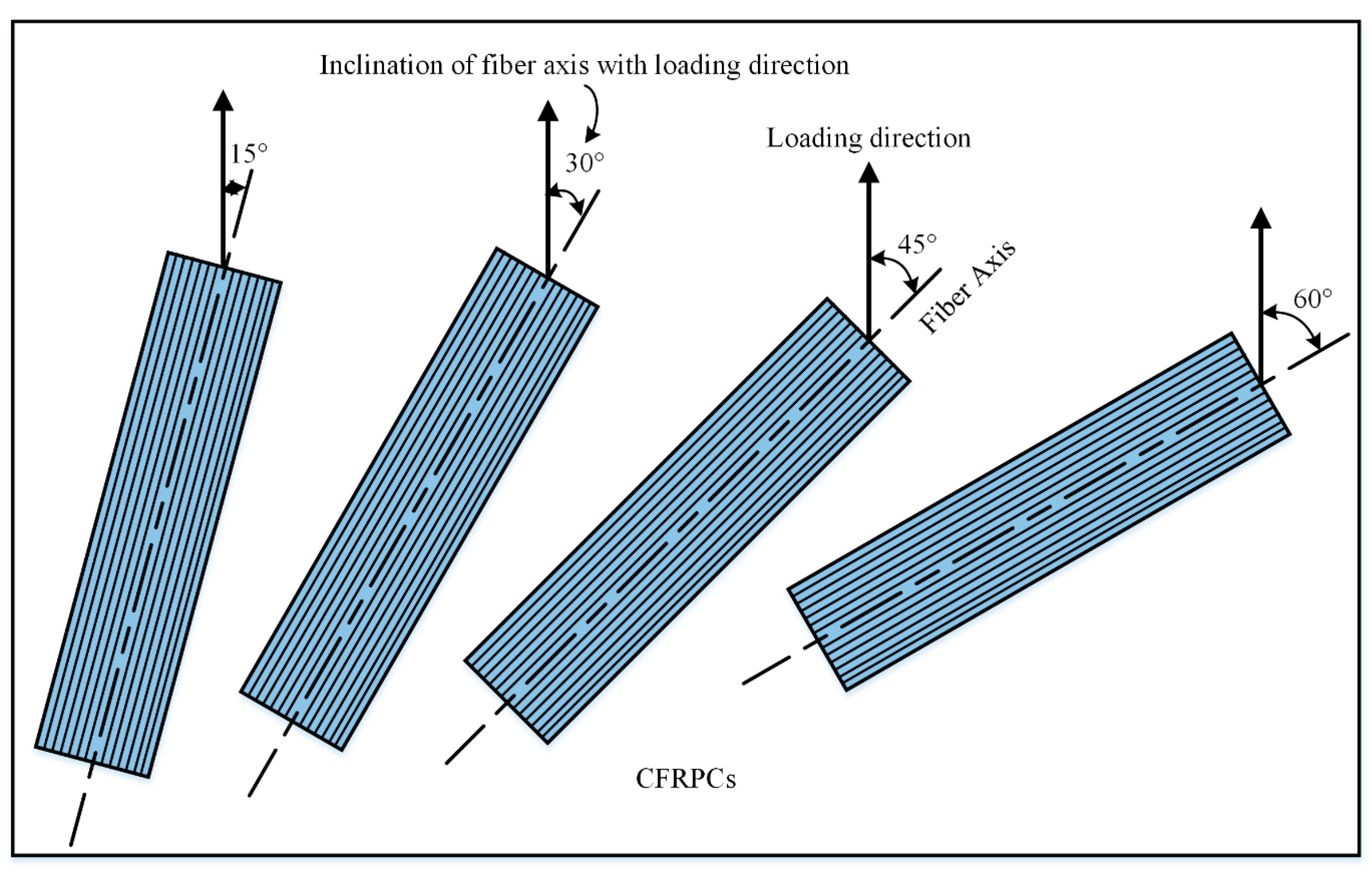
Interaction between fibers and matrix at the meso scale is analyzed against the damage initiation under cyclic loading conditions. S–N curves are obtained at stress ratios of 0.2, 0.4, 0.6, and 0.8 with loading inclination of 15°, 30°, 45°, and 60°.
2. Materials and Methods
The polyacrylonitrile-based long carbon-fiber PC402H was used as the reinforcing material. High-modulus (~240 GPa) carbon fibers were procured from Bhor Chemicals and Plastics Pvt. Ltd., Mumbai, India. Epichlorohydrin bisphenol-A epoxy resin with amine hardener was used as the matrix material and mixed in a ratio of 100:60.
The CFRPCs were manufactured using a vacuum-assisted resin infusion microwave curing process (VARIMC). The process is known for the manufacture of high-grade fiber composites with minimum defects [
23,
24]. Microwaves help in curing the composites uniformly with a high degree of cure, and vacuum (0.1 MPa) ensures high density by removing the entrapped air from the composites [
25]. The composites were manufactured with carbon-fiber weight percentages of 45%, 55%, and 65%. The polytetrafluoroethylene (PTFE) mold and vacuum bagging material used was microwave transparent. Aluminum tape was used to avoid arcing in the microwave by proper masking of carbon fibers. A multimode commercial microwave applicator (Make: VB Ceramics, Chennai; Model: 700DEG) with constant microwave power of 360 W and fixed microwave frequency of 2.45 GHz was used. The temperature was monitored by an IR pyrometer mounted on the microwave applicator. Other details of the manufacturing of the CFRPCs are mentioned in
Table 1.
The flow chart in
Figure 1 illustrates the interaction between macro and meso scales in the investigation of fatigue behavior in carbon-fiber-reinforced polymer composites (CFRPCs). At the macro scale, experimental fatigue tests were conducted on CFRPCs with varying fiber mass fractions to gather data on their fatigue performance. The Goodman equation presents a linear relationship. If the exponent, denoted as “n”, takes a value of two, and the mean stress is normalized by the ultimate tensile strength, the equation transforms into the Gerber equation, which takes on a parabolic form. The Goodman equation has demonstrated remarkable effectiveness in addressing the impact of mean stress within the tension–tension quadrant. The Goodman equation is widely utilized to determine the fatigue design limit of metals when subject to tensile mean stress at various fatigue-life durations. Nevertheless, it is worth noting that certain investigations have indicated that the actual influence of mean stress lies somewhere between the predictions of the Goodman equation and the Gerber equation. In the Modified Gerber equation, the mean stress is normalized using the creep rupture strength instead of the static tensile strength and can proficiently present the mean stress effect during the cyclic loading [
26,
27]. Subsequently, Modified Gerber equation parameters, a common fatigue model for ductile materials, were determined based on the experimental results. These experimentally determined parameters, along with the composite properties, were then fed to the Digimat
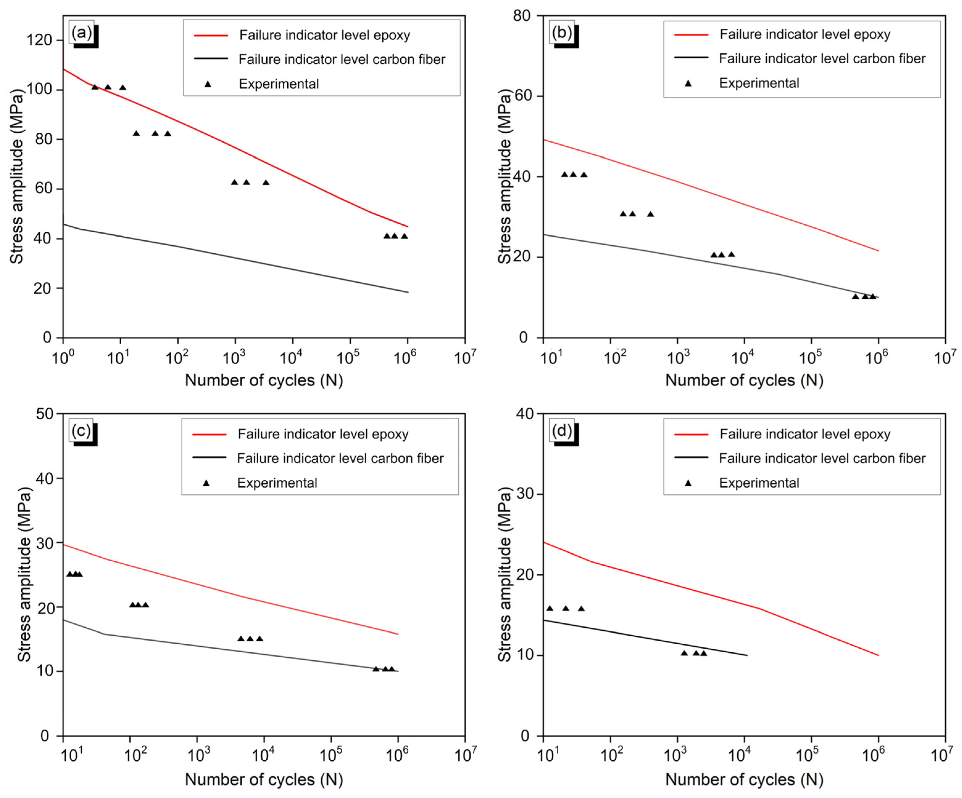
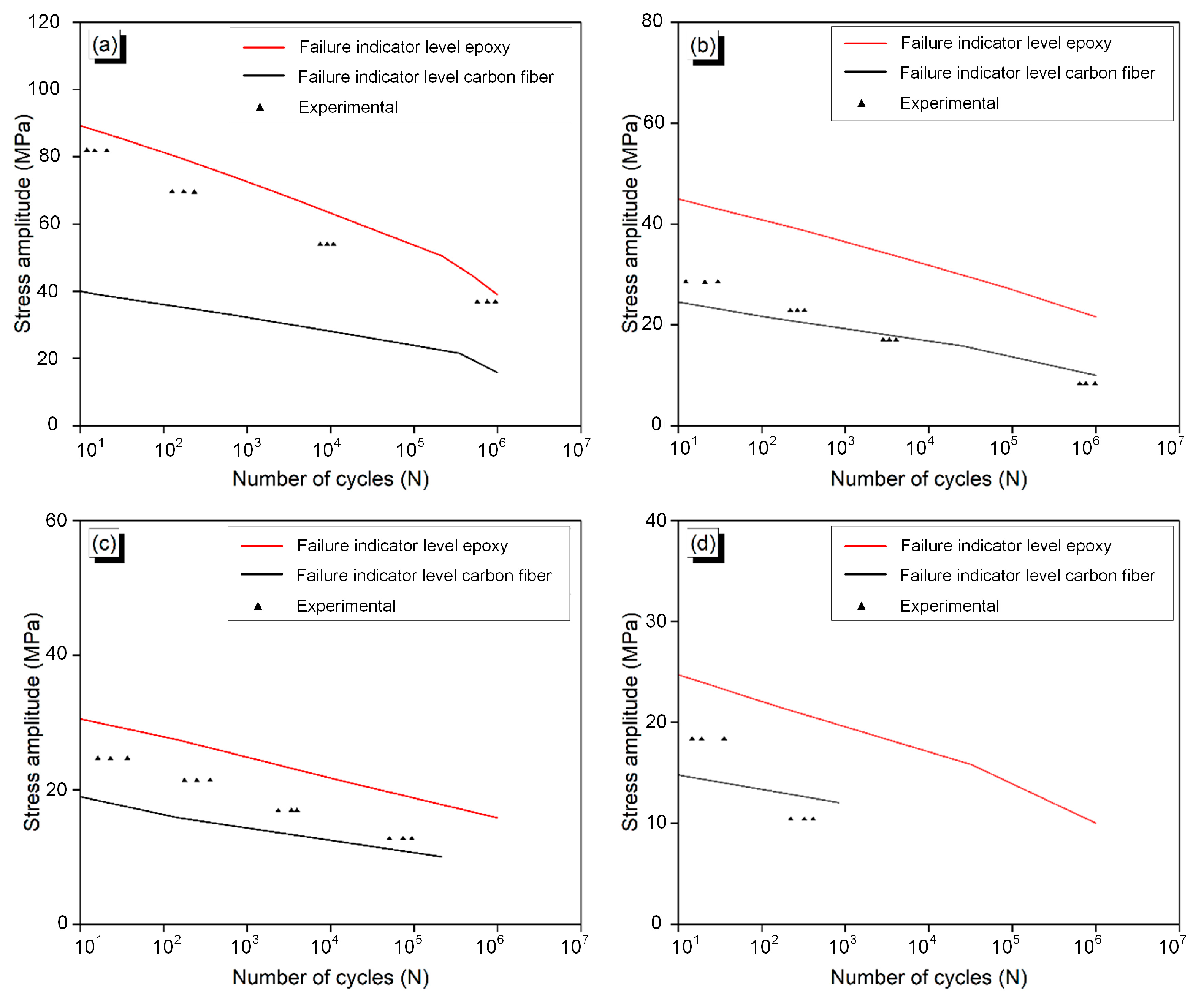
® 2022.4 software, a multiscale modeling tool that can simulate the mechanical behavior of composites. By utilizing the Modified Gerber criteria and the Tsai–Hill failure indicator, the software predicted fatigue cycles under different loading directions and stress ratios. Finite-element (FE) simulations were conducted to further analyze the composite’s behavior and obtain von Mises stress contours at various loading conditions. Finally, the predicted S–N (stress–number of cycles) curves were compared and validated against the experimental fatigue data to assess the models’ and simulations’ accuracy and reliability. This comprehensive approach helps researchers and engineers gain insight into the fatigue performance of CFRPCs under different conditions and optimize their design and usage in various practical applications.
2.1. Multiscale Fatigue Performance
2.1.1. Macro Scale
Tension–tension fatigue tests were conducted on an Instron 8802 hydraulic universal testing rig with an accuracy of ±0.2 kN. At least five samples with the same parameters were used for the fatigue test to ensure repeatability. The tension–tension fatigue behavior was analyzed in accordance with ASTM 3479 [
28]. The strength of the composites decreases rapidly after relatively few cycles but remains approximately constant up to around 80% of fatigue life [
29]. Therefore, 0.8 of the original strength is taken as the fatigue life. The load was first increased to reach the maximum stress, and subsequently, constant amplitude load was applied for an infinite number of cycles or until the failure of the composite. The ultimate tensile strength (UTS) of the CFRPCs was calculated, and its different percentage levels were used to plot the maximum stress (S) versus number of cycles (N) to failure (S–N) curve for tension–tension fatigue analysis. The experiments were carried out with a symmetric triangular waveform with a stress ratio (R) of 0, 0.2, 0.4, and 0.6 at a fixed frequency of 10 Hz. All the experiments were carried out at a controlled room temperature (22 ± 1 °C). Emry cloth was used as the interface between grips and the specimen in the serrated wedge grips to avoid the sudden fracture at the gripping portion of the composites according to the ASTM standard D3039 [
30]. At least three tensile–tensile fatigue experiments were conducted at each stress ratio and at three different stress amplitudes. A total of 36 fatigue experiments were initially conducted to draw the constant life diagram, which was further used to find the fatigue parameters. Finally, experimental S–N curves were drawn at different stress ratios and loading inclinations, and were compared with the predicted fatigue life.
The fracture mechanisms of CFRPCs under cyclic loading were analyzed using scanning electron microscopy (SEM) (Make: FEI, USA, Model: NOVA, NANO SEM). Gold coating of 5 nm was placed on the surface of specimens to avoid the formation of an electrostatic charge cloud.
2.1.2. Macroscale Modeling
Carbon-fiber composites exhibit complex microstructures, where the individual fibers interact with the surrounding matrix at the meso scale, and these interactions collectively influence the overall mechanical behavior of the material at the macro scale. Mesoscale modeling is implemented to know the effect of fatigue loading on the individual constituent of the composite. The mean field homogenization technique is utilized to find the mesoscale S–N curves at constituent levels. Mean field homogenization provides a computationally efficient way to estimate the effective properties of complex materials with microstructural heterogeneities [
31].
The Representative Volume Element (RVE) approach is employed to capture the mesoscale behavior of the composite. RVE models consider the unit cell structure containing fibers and matrix, allowing for the analysis of stress and strain distributions within the composite under cyclic loading. Mallick and Zhou [
27] proposed a modified version of the well-known stress-based Gerber criteria, which considers the influence of mean stress on the fatigue strength of glass fiber-reinforced polyamide-66 composites. The non-dimensional equation for the Gerber equation was derived by expressing it in terms of ultimate tensile strength and incorporating fatigue strength factors (α) and creep rupture strength factor (β), as shown in Equation (1).
In the given equation, the parameters α and β are to be adjusted, while σm represents the mean stress, and σa and σu represent the stress amplitude and ultimate tensile strength, respectively. Normalizing the data by σu enables the unification of the data considering sample orientation and atmospheric conditions.
The parameters
α and
are optimized to better fit the full database and take the power-law form, as shown in Equations (2a) and (2b).
Here, Nc is the number of fatigue cycles and , , , and are the constants to be determined by curve fitting.
The Modified Tsai–Hill criterion, proposed by Bernasconi et al. [
32] and De Monte et al. [
33], incorporates the Tsai–Hill criterion adapted for cyclic loading to predict fatigue failure and considers the influence of fiber orientation relative to the loading direction. The stress-based Tsai–Hill failure indicator was used in conjunction with Modified Gerber fatigue criteria. The criterion incorporates both normal and shear stresses to evaluate material failure. It is commonly used to predict failure modes such as fiber rupture, matrix cracking, or delamination in fiber-reinforced composites. The Tsai–Hill equation, which corresponds to Axis 1, is given by Equation (3).
where
ij denotes the component of the stress amplitude corresponding to the local axis system, and X, Y, and S denote the axial, in-plane, and shear stress amplitude at failure.
The Tsai–Hill criterion is an empirical failure criterion that predicts failure based on a linear combination of the material’s strength properties. The Tsai–Hill criterion compares the composite’s stress components to their respective strength values and calculates a failure index. Failure is predicted if the failure index exceeds a predefined threshold (usually set to 1).
The various loading directions of 15°, 30°, 45°, and 60° to the fiber axis were used for the fatigue analysis of the CFRPCs, as shown in
Figure 2.
4. Conclusions
In conclusion, the integration of meso–macro multiscale analyses and experimentation has proven to be a valuable approach to understanding and predicting the mechanical behavior of fiber composites. By the combination of mesoscale modeling, the details of composites at constituent levels are captured, and a global representation of the material behavior is estimated at the macro scale. Therefore, a more comprehensive understanding of the material response has been achieved by multiscale analyses. The meso–macro analyses approach allows for the incorporation of various failure mechanisms and their interactions at different-length scales. This enables accurate predictions of the material’s fatigue life under different loading conditions. By considering the interaction between fibers and matrix at the meso scale, fatigue modeling provides a deeper understanding of the underlying failure mechanisms and damage initiation and propagation within the composite material. The integration of experimentation plays a crucial role in validating and calibrating the meso–macro models. Experimental testing provides essential data for characterizing the material properties, failure modes, and fatigue behavior. By comparing the model predictions with experimental results, the accuracy and reliability of the models can be assessed, and necessary adjustments can be made to improve their predictive capabilities. The following capabilities of the models are found:
- –
The model is capable of predicting the fatigue life at the matrix and reinforcement level.
- –
Fatigue life can be predicted at various stress-ratio levels.
- –
Fatigue can be predicted in different loading directions.
Overall, the combination of meso–macro multimodeling and experimentation has facilitated significant advancements in our understanding of fiber composite mechanical behavior. The integrated approach has the potential to drive further improvements in material design, optimization of composite structures, and prediction of their performance under various operational conditions. It also offers insights into the development of new composite materials with enhanced mechanical properties and increased durability.


 ,
, 


