Article

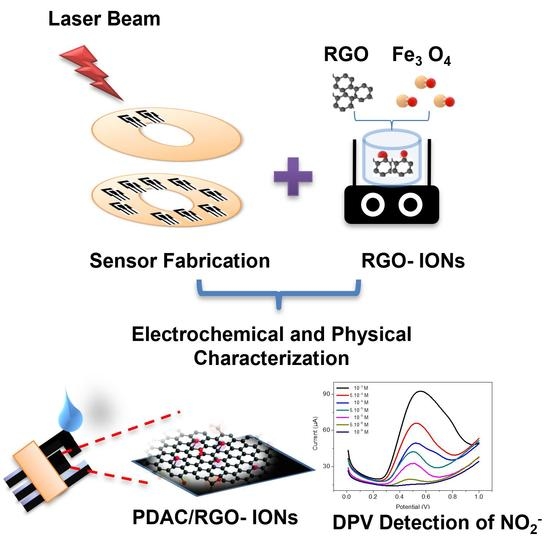
Stability Enhancement of Laser-Scribed Reduced Graphene Oxide Electrodes Functionalized by Iron Oxide/Reduced Graphene Oxide Nanocomposites for Nitrite Sensors

1
Professorship Measurement and Sensor Technology, Chemnitz University of Technology, 09111 Chemnitz, Germany
2
NANOMISENE Lab, LR16CRMN01, Centre for Research on Microelectronics and Nanotechnology of Sousse, Technopole of Sousse, B.P. 334, Sahloul, Sousse 4034, Tunisia
3
Higher Institute of Applied Sciences and Technology of Sousse, University of Sousse, 4003 Tunisia of Sousse, GREENS-ISSAT, Cité Ettafala, Ibn Khaldoun, Sousse 4003, Tunisia
4
Laboratory of Research on Polymers and Nanomaterials, Institute of Chemistry, University of Brasilia, Brasília 70910-900, DF, Brazil
*
Authors to whom correspondence should be addressed.
J. Compos. Sci. 2022, 6(8), 221; https://doi.org/10.3390/jcs6080221
Submission received: 4 July 2022 / Revised: 19 July 2022 / Accepted: 28 July 2022 / Published: 3 August 2022
(This article belongs to the Special Issue Graphene Oxide Composites)

Abstract

:
An iron oxide/reduced graphene oxide (ION-RGO) nanocomposite has been fabricated to functionalize a low-cost electrochemical nitrite sensor realized by light-scribed reduced graphene oxide (LRGO) electrodes on a PET substrate. To enhance the stability and adhesion of the electrode, the PET substrate was modified by RF oxygen plasma, and a thin layer of the cationic poly (diallyl dimethyl ammonium chloride) was deposited. Raman spectroscopy and scanning electron microscopy coupled to energy-dispersive X-ray spectroscopy (SEM-EDX) reveal that the light-scribing process successfully reduces graphene oxide while forming a porous multilayered structure. As confirmed by cyclic voltammetry, the LRGO electrochemical response to ferri-ferrocyanide and nitrite is significantly improved after functionalization with the ION-RGO nanocomposite film. Under optimized differential pulse voltammetry conditions, the LRGO/ION-RGO electrode responds linearly (R2 = 0.97) to nitrite in the range of 10–400 µM, achieving a limit of detection of 7.2 μM and sensitivity of 0.14 µA/µM. A single LRGO/ION-RGO electrode stands for 11 consecutive runs. The novel fabrication process leads to highly stable and reproducible electrodes for electrochemical sensors and thus offers a low-cost option for the rapid and sensitive detection of nitrite.

Graphical Abstract

1. Introduction

Nitrite (NO2) is an inorganic ion, which is omnipresent in natural environments such as food, water, and soil [1]. In current practice, nitrite has been primarily utilized as a fertilizer, corrosion inhibitor, and food preservative in sausage meat. It is also used as a drug component for lowering blood pressure in clinical therapy [2]. However, nitrite can have adverse effects, especially in excessive intake. Long-term accumulation of nitrite ions or overdose can convert normal hemoglobin “blood oxygen carrier” to methemoglobin “non-oxygen carrier,” thus causing hemoglobin to lose the ability to carry oxygen and leading to brain damage, congenital disabilities, and even death [3]. The World Health Organization (WHO) sets the limit for nitrite in drinking water at 3 mg L1 [4]. Consequently, there is an ever-increasing demand for analytical tools to monitor nitrite in water.
Due to its suspected toxicity, the sensitive detection of nitrite is significant for protecting people and the environment. As a result, different analytical methods have been developed lately for the determination of nitrite concentration, including chromatography–mass spectrometry [5], UV-spectrophotometry [6], optical sensors [7], and electrochemical sensors [8].
Electrochemical sensors have decisive advantages over conventional analytical methods, including rapid response, ease of operation, low cost, and high sensitivity [8,9]. Indeed, they can be implemented for on-site monitoring of nitrite in the field [9]. The detection of nitrite ions with electrochemical sensors is based on monitoring oxidation/reduction over diverse types of working electrodes [10,11]. Nevertheless, nitrite oxidation occurs at a high potential and shows slow kinetics [12]. The employment of nanomaterials—in particular, carbon-based ones [13] such as reduced graphene oxide (RGO), carbon nanotubes (CNT) and metal oxide nanoparticles such as iron oxide (ION) [14], gold nanoparticles (AuNPs) [15], and carbon nanotubes (CNT) decorated with gold nanoparticles (AuNPs) [16]—improves the charge-transfer across the electrolyte/electrode interface by providing additional adsorption and electrocatalytic sites owing to their enhanced surface-to-volume ratio.
Graphene oxide (GO) is a suitable candidate for electrochemical sensors. However, a challenging issue when developing graphene-oxide-based flexible devices is the reduction to its electrically conducting form, namely RGO. Many reduction methods exist, but unlike conventional GO reduction methods [17,18], direct electrode writing techniques do not require post-processing, cleanroom operations, or expensive materials but are readily scalable and cost-effective. The laser reduction method is one of these techniques [19,20]. The laser-induced ruptures and wrinkles on the RGO surface contribute as active sites for electrochemical reactions [18]. Lin’s group [21] successfully fabricated a nonenzymatic glucose sensor by using DVD laser-scribed graphene (LSG). In this work, only the working electrode was developed with the LSG technique, and to complete the three-electrode system, a Pt counter electrode was used with an SCE reference electrode. Another work was carried out by this group of researchers where they achieved non-enzymatic hydrogen peroxide detection with the same technique [22]. Additionally, the LSG method of patterning GO/RGO is simple, easy, and low-cost. However, the quality of the laser-reduced GO is low in terms of adhesion on the substrate and effectiveness of the reduction process. This low quality of the produced graphene oxide is due to insufficient reduction, especially the limited laser power [23].
In this contribution, we describe a reproducible and straightforward method for fabricating low-cost electrochemical sensors by using laser-scribing on a coated layer of graphene oxide on PET substrate. The proposed method enables the fabrication of more than 20 three-electrode devices on one single DVD previously coated by GO. The fabrication method are described in detail in our previous work [24,25]. Far from that, this paper deals with more sensitive detection of nitrite and larger detection range and sensor stability. It also focuses more on physical characterization (i.e., XRD, Raman and TEM images of ION-RGO, as well as Raman spectroscopy of PDAC/GO- and PDAC/RGO-coated films). Several electrochemical characterizations were carried out, such as cyclic voltammograms for modified RGO and bare electrode in different buffers as well as electrochemical impedance spectroscopy, where the corresponding equivalent circuit modeling was found. With new investigations, the detection of NO2 at different pHs was investigated to extend the detection range, and a considerable enhancement was noticed in the sensitivity and repeatability.
The DVD is burned for at least ten cycles to obtain consistently reduced areas. The number of burnings was optimized to reduce the entire surface. The challenge of poor adhesion of the GO layer to the surface that may occur, leading to easy scratching or detaching of RGO layer, is studied. In this regard, significant efforts have been devoted to enhancing the adhesiveness between the PET and the layer of RGO and the stability of the obtained electrodes. Plasma treatment of the PET substrate followed by deposition of poly (diallyl dimethyl ammonium) hydrochloride (PDAC) is considered as an effective strategy to enhance the adhesion of GO. Further surface modification of the working electrode with a PDAC/ION-RGO nanocomposite film has been performed to improve its electrocatalytic effect toward nitrite electro-oxidation.

2. Materials and Methods

2.1. Chemicals and Materials

The materials NaNO3 99%, Na2HPO4, NaH2PO4, NH4OH (47%), HCl (37%), NaOH (97%), FeSO4 7H2O (99%), K3Fe (CN)6 (99%), and PDAC (Mw 400,000 g mol1; 20% wt aqueous solution) were purchased from Sigma-Aldrich and used as received. Commercial graphene oxide (GO) (Graphenea, San Sebastián, Spain) and lab-made [26] GO samples were employed for electrode fabrication and modification, respectively. Poly(ethylene terephthalate) (PET) sheets (Melinex 506, thickness: 100 µm) were employed as substrates for the deposition of GO films to be used for laser scribing of electrodes. All water used for solutions preparations and cleaning procedures was an ultrapure type (18 MΩ cm resistivity).
The ION-RGO nanocomposite was prepared according to the method described by Teo et al. [27]. The lab-made GO sample was chosen for this synthesis because it is free of any additives. The lab-made GO suspension (200 mL, 0.1 g L1, pH 11) was magnetically stirred while 10 mL of FeSO4·7H2O solution (0.05 mol L1) was added dropwise at ambient room temperature. The reaction remained under magnetic stirring and at room temperature for another 30 min. A black precipitate made of ION-RGO formed immediately and was separated with the aid of a magnet. The supernatant was removed, while the ION-RGO was washed with ultrapure water until the supernatant reached neutral pH. Afterward, the solid ION-RGO was suspended in NH4OH solution (pH 8) by sonication (power amplitude: 140 W; duty cycle: 1 s “on”, 1 s “off”; 30 min) and centrifuged (5000 rpm, 10 min). The final concentration of the ION-RGO suspension was 1.16 g L1. At this condition, the ION-RGO suspension displayed a negative zeta potential (−20.0 ± 1.0 mV).

2.2. Device Fabrication and Microstructural Analysis

The PET substrate was cut into the shape of a DVD, as depicted in Figure 1a. Then, it was carefully cleaned with tissue paper embedded in isopropanol. This substrate is labeled as untreated PET. Afterward, PET substrate was submitted to two different surface treatments to maximize the adhesion of the GO film, as follows. In the first, PET was immersed for 10 min into an aqueous PDAC solution (1 g L1), then rinsed with ultrapure water, and left to dry in ambient air. This is labeled PET/PDAC. In the second treatment, PET was submitted to oxygen plasma (Evactron10, two minutes, 50 Pa working pressure), followed by immersion into the same PDAC solution, then rinsed in ultrapure water and dried in ambient air. This is labeled PET/plasma/PDAC. A volume (15 mL) of an aqueous suspension of commercial-grade GO at 3.0 g L1 was then casted with a syringe on each type of PET substrate and left to dry in ambient air for 24 has shown in Figure 1b. Afterward, the GO-coated PET substrates were assembled onto a DVD and introduced in the Laser-Scribe rewriter driver (power output = 5 mW, wavelength = 788 nm). The complete set was submitted to 10 burning cycles to obtain consistent RGO areas. A three-electrode configuration structure was designed using Inkscape software, as shown in Figure 1c. Electrodes are shown in Figure 1d. Subsequently, each device was cut into individual units, and the electrode connection pads were painted with Ag ink to ensure electrical contact with the electrochemical workstation. A pseudo-reference electrode was obtained after painting one of the LRGO electrodes in the active area with Ag/AgCl ink. The active site was isolated from the connection pads with a thin layer of nail polish. A digital photo of the finished fabricated device is provided in Figure 1e.
The working electrode was modified with PDAC/ION-RGO bilayers to improve the electrocatalytic effect toward nitrite oxidation. As the LRGO surface is negatively charged due to remaining oxygenated functional groups that were not eliminated during laser reduction, the bilayers started with a positively charged layer of PDAC, which was followed by a negatively charged layer of ION-RGO. A drop of PDAC solution (1 g L1) was casted onto the electrode and left to rest for 10 min. Afterward, the electrode was rinsed with ultrapure water and blow-dried with compressed air, as Figure 2 shows. The same procedure was identically repeated with the ION-RGO suspension. One and two PDAC/ION-RGO bilayers were applied and tested.
The ION-RGO nanocomposite sample was evaluated by X-ray diffractometry (Bruker D8 Diffractometer; Cu-Kα radiation λ = 0.154 nm; 0.05° resolution; and 0.5° min1 rate), transmission electron microscopy (TEM, JEOL JEM-2100, at 200 kV), and Raman (Horiba T6400; 532 nm laser line; 0.1 cm1 resolution; laser power 2 mW) spectroscopy. In addition, the ION-RGO colloid was characterized by measuring the zeta potential and hydrodynamic diameter with a Nano Zetasizer ZS90 (Malver Instrument). Scanning electron microscopy (SEM) images were carried out for the electrode-functionalized films using FEI Nova Nano SEM 200.

2.3. Electrochemical Measurements

All electrochemical experiments were carried out with a PalmSens 4 potentiostat at room temperature (25 °C). The electrochemical properties and stability of bare and PDAC/ION-RGO-modified LRGO electrodes was exclusively investigated by cyclic voltammetry (CV), both in the plain electrolyte phosphate-buffered saline (PBS) and with K3Fe (CN)6 (1 mmol L1 in KCl 0.1 mol L1) as the redox probe, at different scan rates (25 mVs1 to 200 mVs1). After that, nitrite detection was evaluated by differential pulse voltammetry (DPV) and impedance spectroscopy (EIS). The optimum electrolyte pH was determined after measurements performed in PBS buffer (0.1 mol L1), at pHs varying between 3.5 and 7.4. At the best pH condition, the effects of substrate treatment and PDAC/ION-RGO bilayers on the sensing performance were evaluated.

3. Results and Discussion

3.1. Structural and Morphological Characterization of ION-RGO Nanocomposite, LRGO, and LRGO/PDAC/ION-RGO Electrodes

The structural and morphological characteristics of the ION-RGO nanocomposite are provided in Figure 2. Figure 2a reports the XRD diffractogram, which shows the signature of the cubic inversed spinel structure expected for iron oxides such as maghemite and magnetite [28]. Using the diffraction angle of the most intense peak, (311), it was possible to estimate the interplanar distance (d) and the lattice parameter (a) or the ION phase according to Equations (1) and (2), as follows:
n λ = 2 d s i n θ  
1 d 2 = h 2 + k 2 + l 2 a 2  
where h, k and l are Miller indices [29]. According to this, the lattice parameter is 8.343 Angstroms, which is closer to that of maghemite (8.351) [30]. The full half-maximum (β) of the (311) diffraction peak was further employed to determine the crystallite size (τ) using the Scherrer equation, as follows:
τ = K λ β c o s θ
where K is a dimensionless shape factor, which has typical value of about 0.9; λ is the X-ray wavelength; β is the line broadening at half the maximum intensity (FWHM), after the subtracting of the instrumental line broadening, in radians; and θ is the Bragg angle [31].
The determined value is 15.4 nm. Figure 2b shows the Raman spectrum in which ION and RGO phases are readily detected. The ION phase appears between 200 and 800 cm, for which the doubled signal is deconvoluted into five Lorentzian curves assigned to both maghemite and magnetite [32]. The RGO phase is confirmed by the D and G bands located at 1334 cm1 and 1597 cm1, respectively [26].
It is worth mentioning that the D to G intensity ratio (ID/IG) is 1.1 in ION-RGO, which is greater than that of plain GO (0.84), thereby suggesting that GO is converted to RGO after ION-RGO is produced. Figure 2c provides a TEM image of the nanocomposite in which one can see the RGO sheet being decorated with spherical-like ION. Altogether, these results confirm the successful synthesis of ION-RGO, in which RGO sheets are decorated with spherical ION, the latter being composed of a mixture of maghemite and magnetite phases.
The structural and morphological characteristics of GO, bare LRGO, and LRGO/PDAC/ION-RGO electrodes are shown in Figure 3. All of them were assembled onto a PET-plasma-PDAC substrate, which was found to be the best one in terms of adhesion of the GO film, as we shall see later.
Before the laser treatment, as seen in Figure 3a, the GO film uniformly covers the entire PET substrate underneath. Few wrinkles are seen, which is typical of a GO with few layers. After laser reduction, in Figure 3b the surface morphology undergoes a drastic change, as it becomes rougher and parts of the film are peeled off from the substrate. It is also noticed that regular straight tracks along the surface arises due to the laser scribing process [33,34]. More wrinkled and stacked LRGO sheets are observed due to the increased number of C=C bonds, which are shorter than C-C bonds and cause substantial local stress. Figure 3c,d show the LRGO electrode surface-modified with one PDAC/ION-RGO bilayer. The surface morphology is composed of RGO sheets decorated with spherical-like and agglomerated ION. Nevertheless, this feature is uniformly seen over the entire surface, thus confirming the successful deposition of the PDAC/ION-RGO bilayer.
Figure 4 shows the elements (C, O, and Fe) obtained from EDX, which further confirm the efficiency of the laser reduction process shown in Figure 4a,b, as well as successful deposition of ION-RGO in Figure 4c,d.
Raman spectra are shown in Figure 5a,b for graphene oxide before and after reduction, where the reduced graphene oxide phase is confirmed by the D and G bands located at 1330 cm1 and 1590 cm1, respectively.
By calculating the D to G intensity ratio (ID/IG), it is found to be 1.27 in GO, which after reduction gives the value of RGO (1.16), thereby suggesting that GO is converted to RGO. Additionally, all D peaks were changed after the reduction treatment. These changes reflect the decrease in the oxygen containing groups, which decreased by reduction with the DVD laser.
To evaluate the efficiency of each treatment of the PET’s surface on the adhesion of the GO film, the scotch tape test was performed, and digital photographs were registered. As shown in Figure 6, the GO film deposited onto untreated PET (Figure 6a) has inferior adhesion, since the tape entirely removes it. The adhesion is, however, slightly improved when a PDAC layer is deposited before the GO film (Figure 6b). The adhesion is improved further when the PET substrate is treated with oxygen plasma followed by PDAC deposition (Figure 6c). Oxygen plasma oxidizes the PET surface and exposes carboxylic acid groups, making PET more hydrophilic [35]. As a cationic polyelectrolyte, PDAC is capable of adsorbing onto oxygen plasma-treated PET by electrostatic attractions, which is stronger than hydrophobic interaction. In the subsequent step, GO adsorbs onto PDAC-treated PET by electrostatic attraction [36]. This model explains why the adhesion of the GO film is improved after PET is plasma-treated and modified with PDAC.

3.2. Electrochemical Properties of LRGO Electrodes

Figure 7 shows cyclic voltammograms of the current and the oxidation potential peak (Epa) of nitrite performed with untreated-PET/LRGO and PET-plasma-PDAC/LRGO during successive cyclic voltametric runs. Electrodes were copiously rinsed with DI water to remove the oxidation products and nitrite between each measurement. It is seen that PET-plasma-PDAC/LRGO lasts longer, which is ascribed to the stronger adhesion of the GO film to this surface-treated PET. This result further corroborates the scotch tape test. Therefore, the PET-plasma-PDAC/LRGO was chosen for the next experiments.
Figure 8 shows the CV curves at several scan rates in 0.1 M KCl solution containing 1.0 mM [Fe (CN)6]3−/4− (Figure 8a,b) and current versus the square root of the scan rate (Figure 8c) for the ferri/ferrocyanide redox pair for unmodified and PDAC/ION-RGO-modified LRGO. In Figure 8a, CV curves show that for the unmodified electrode, anodic/cathodic peak currents (ipa and ipc) are 130 µA/−133 µA and ∆Ep is 539 mV in scan rate 50 mV/s, whereas with the modified electrode, ipa/ipc increase to 182 µA/−172 µA and ∆Ep decreases to 229 mV at the same scan rate. In Figure 8c, it is noticed that ferri-ferrocyanide interconversion is a diffusion-controlled process at both electrodes since ipa/ipc scales linearly with v1/2. The experimental data were fitted using the modified Randles–Sevcik Equation for an irreversible process.
i p a i r r = ± 0.496 α n F A r e a l C n F D R T
in which α is the charge-transfer coefficient (assumed to be 0.5), n is the number of transferred electrons (=1 for ferri-ferrocyanide), F is the Faraday constant (96,500 C mol1), Areal is the electroactive area (in cm2), D is the ferricyanide diffusion coefficient (7.6 × 10‒6 cm2 s 1), R is the universal gas constant (8.31 J K1 mol1), and T is the temperature (298.15 K) [37]. The estimated area for the electrodes is 0.2 cm2 (unmodified) and around 0.3 cm2 (PDAC/ION-RGO-modified electrode). Therefore, it is seen that the LRGO electrode’s performance is significantly improved upon the modification with PDAC/ION-RGO nanocomposite.

3.3. Electrochemical Application: Oxidation of Nitrite

The obtained sensors are applied for the detection of nitrite ions to prove their efficiency. Figure 9 shows the CV curves registered with the bare and ION-RGO-modified LRGO electrodes in the presence of nitrite 103 mol.L1 in PBS pH 5.7. Here, it is also clear that the LRGO electrode responds better when modified by ION-RGO, which provides a higher oxidation current and lower oxidation potential. Nevertheless, the irreversible feature of the oxidation process is not changed even after electrode modification.
Figure 10a reports CV curves registered at different scan rates in the presence of nitrite 104 mol.L1 in PBS pH 5.7 using the ION-RGO-modified electrode. A current increase is seen accompanied by an anodic shift of the oxidation potential, which further corroborates the irreversibility of the oxidation process. The plot showed that with increasing scan rates from 25 to 200 mV/s, the peak currents increased. The oxidation reaction of nitrite occuring at the electrode/aqueous electrolyte interface is of the charge transfer type, more precisely electron transfer; if the curve is linear, the reaction will be of the diffusion type.
For further investigation of the effect of modification on the sensor, EIS measurements are carried out on bare and ION-RGO-modified electrode. It is illustrated in Figure 10b that there is a decrease in the semi-circle region of the Nyquist plots from bare to modified ION-RGO electrode. The modified electrode possesses the smallest impedance with smallest Rct, while the bare has the highest Rct.
The ION-RGO nanocomposite decreases the charge transfer resistance in the electrode–electrolyte interface and increases the electroactive surface area, thereby enhancing the kinetics of electrochemical reaction. RS is the resistance of the electrolyte; it is approximately 700 Ω for the evaluated electrodes as bare electrodes are not particularly good conductors.
The influence of the electrolyte’s pH is shown in Figure 10c,d. An optimum pH of 5.7 is observed, wherein nitrite oxidation provides the highest current. Conversely, the pH seems to not affect the oxidation potential, which remains unaltered in the investigated pH range. It is known that nitrite is quite unstable in strongly acidic media. At pH > 6, its electro-oxidation is difficult because of the lack of protons. It has, therefore, an optimum pH in which nitrite is favorably oxidized. The results shown agree with those in [38].

3.4. Performance of LRGO/PDAC/ION-RGO Electrode in the Voltammetric Determination of Nitrite

The previous sections have shown that the LRGO/PDAC/ION-RGO electrode was the best among other electrode architectures in terms of stability and sensitivity to nitrite. Thus, its performance was evaluated further to determine the advantages and drawbacks in the voltametric detection of nitrite. For this purpose, DPV was chosen as the detection method because of its high sensitivity.
Figure 11 shows the DPV curves for nitrite at different concentrations in PBS pH 5.7. As shown by the calibration curve provided in the inset, Ipa scales linearly with the nitrite concentration in the range between 10 µM and 400 µM. The calibration curve is fitted by the following linear equation: Ipa (µA) = 9.41 + 0.14 [NO2], R2 = 0. 979. The sensitivity is 0.14 µA/µM. The limit of detection (LOD) is 7.2 µM, and it was determined by the relation 3 sx/y/m, in which sx/y is the residual standard deviation (obtained from the linear regression), and m is the slope of the analytical curve. This value is much lower than the value mentioned by the guideline of WHO (65.2 μM) for nitrite in drinking water.
The obtained performances of the LRGO/PDAC/ION-RGO electrode were compared to other nitrite sensors previously published in the literature with different functionalization materials and approaches, as shown in Table 1.
The reproducibility of the proposed fabrication process has been studied as it is an important parameter to evaluate sensors’ performance. This figure was evaluated by measuring Ipa and Epa with a single electrode after successive runs, with several electrodes fabricated in the same and different batches. A single electrode stands for at least 12 runs, and as shown in Figure 12a–c, comparable results are achieved with electrodes fabricated in the same batch and different batches, as shown in Figure 12a,d.
Figure 12d shows the response of sensors taken from six different batches fabricated under the same conditions and following the same fabrication process. The electrodes give the same peak potential, around 5.3 V, which proves the ability of the sensor to supply the same result under the same circumstances repeatedly.
These results show that the proposed laser-scribing process is quite reproducible, and LRGO electrodes can achieve fair performance when compared to other conventional carbon-based sensing platforms.

4. Conclusions

Within the framework of this study, a reliable, low-cost, and simple methodology was developed and optimized to realize laser-scribed reduced graphene oxide electrodes. After functionalization with an iron oxide nanoparticle/reduced graphene oxide nanocomposite, the as-produced LRGO/ION-RGO electrode was capable of detecting nitrite within a linear working range of 10−400 µM, providing a limit of detection of 7.21 µM and a sensitivity of 0.14 µA/µM. Additionally, the results showed that the fabrication process is quite reproducible from batch to batch, leading to robust devices displaying high sensitivity and electrochemical stability. This detection methodology is highly promising since it combines low cost, reproducibility, and the possibility of scaling-up, thereby supplying an excellent alternative for electrochemical detection of different analytes of environmental concern.

Author Contributions

Conceptualization, A.B., A.A.-H., O.K. and M.B.A.; formal analysis, A.B. and M.A.G.; investigation, data processing, writing and preparation of original draft, A.B.; Raman and SEM analysis, A.A.-H.; writing–revision and editing, L.G.P., A.A.-H., M.B.A. and O.K.; project administration, O.K. and A.A.-H. All authors have read and agreed to the published version of the manuscript.

Funding

This research was funded by AIF-ZIM within the BiomassSensors Project, no. KK 5087703RH0. O.K. and A.A.-H. acknowledge the financial support from Deutsche Forschungsge-meinschaft (DFG) (PhotoSens project no. KA 1663/12-1).

Institutional Review Board Statement

Not applicable.

Data Availability Statement

Not applicable.

Acknowledgments

Acknowledgment to Alexander von Humbboldt foundation. We thank C. Tegenkamp and D. Dentel from the Institute of Physics (Solid Surfaces Analysis) for providing access to scanning electron microscope (SEM) imaging.

Conflicts of Interest

The authors declare no conflict of interest.

References

  1. Hall, J.O. Nitrate- and Nitrite-Accumulating Plants. In Veterinary Toxicology: Basic and Clinical Principles: Third Edition; Elsevier: Amsterdam, The Netherlands, 2018; pp. 941–946. ISBN 9780128114100. [Google Scholar]
  2. Pooja, D.; Kumar, P.; Singh, P. Sensors in Water Pollutants Monitoring: Role of Material Advanced Functional Materials and Sensors; Springer: Singapore, 2020; p. 320. [Google Scholar]
  3. Moo, Y.C.; Matjafri, M.Z.; Lim, H.S.; Tan, C.H. New Development of Optical Fibre Sensor for Determination of Nitrate and Nitrite in Water. Optik 2016, 127, 1312–1319. [Google Scholar] [CrossRef]
  4. Hutton, G.; Haller, L. Evaluation of the Costs and Benefits of Water and Sanitation Improvements at the Global Level; World Health Organization: Gevena, Switzerland, 1994. [Google Scholar]
  5. Tsikas, D. ReviewMethods of Quantitative Analysis of the Nitric Oxide Metabolites Nitrite and Nitrate in Human Biological Fluids Methods of Quantitative Analysis of the Nitric Oxide Metabolites Nitrite and Nitrate in Human Biological Fluids. Free. Radic. Res. 2009, 39, 797–815. [Google Scholar] [CrossRef] [PubMed]
  6. Thipwimonmas, Y.; Jaidam, J.; Samoson, K.; Khunseeraksa, V.; Phonchai, A.; Thiangchanya, A.; Haw Chang, K.; Fahmi Lim Abdullah, A.; Limbut, W. A Simple and Rapid Spectrophotometric Method for Nitrite Detection in Small Sample Volumes A Simple and Rapid Spectrophotometric Method for Nitrite Detection in Small Sample. Chemosensors 2021, 9, 161. [Google Scholar] [CrossRef]
  7. Awual, M.R.; Hasan, M.M.; Islam, A.; Rahman, M.M.; Asiri, A.M.; Khaleque, M.A.; Sheikh, M.C. Introducing an Amine Functionalized Novel Conjugate Material for Toxic Nitrite Detection and Adsorption from Wastewater. J. Clean. Prod. 2019, 228, 778–785. [Google Scholar] [CrossRef]
  8. Kanoun, O.; Lazarević-Pašti, T.; Pašti, I.; Nasraoui, S.; Talbi, M.; Brahem, A.; Adiraju, A.; Sheremet, E.; Rodriguez, R.D.; Ali, B.; et al. A Review of Nanocomposite-Modified Electrochemical Sensors for Water Quality Monitoring Academic Editors: Najla Fourati And. Sensors 2021, 21, 4131. [Google Scholar] [CrossRef]
  9. Essousi, H.; Barhoumi, H.; Bibani, M.; Ktari, N.; Wendler, F.; Al-Hamry, A.; Kanoun, O. Ion-Imprinted Electrochemical Sensor Based on Copper Nanoparticles-Polyaniline Matrix for Nitrate Detection. J. Sens. 2019, 2019, 4257125. [Google Scholar] [CrossRef]
  10. Tan, J.F.; Anastasi, A.; Chandra, S. Electrochemical Detection of Nitrate, Nitrite and Ammonium for on-Site Water Quality Monitoring. Curr. Opin. Electrochem. 2022, 32, 100926. [Google Scholar] [CrossRef]
  11. Mao, Y.; Bao, Y.; Han, D.X.; Zhao, B. Research Progress on Nitrite Electrochemical Sensor. Chin. J. Anal. Chem. 2018, 46, 147–155. [Google Scholar] [CrossRef]
  12. Zou, H.L.; Qin, L.Y.; Luo, H.Q.; Li, B.L.; Li, N.B. High-Valence Mo(VI) Derived from in-Situ Oxidized MoS2 Nanosheets Enables Enhanced Electrochemical Responses for Nitrite Measurements. Sens. Actuators B Chem. 2021, 337, 129812. [Google Scholar] [CrossRef]
  13. Li, D.; Wang, T.; Li, Z.; Xu, X.; Wang, C.; Duan, Y. Application of Graphene-Based Materials for Detection of Nitrate and Nitrite in Water-A Review. Sensors 2019, 20, 54. [Google Scholar] [CrossRef]
  14. Zhu, N.; Ji, H.; Yu, P.; Niu, J.; Farooq, M.U.; Waseem Akram, M.; Udego, I.O.; Li, H.; Niu, X. Surface Modification of Magnetic Iron Oxide Nanoparticles. Nanomaterials 2018, 8, 810. [Google Scholar] [CrossRef]
  15. Talbi, M.; Al-Hamry, A.; Rios Teixeira, P.; Paterno, L.G.; Ali, B.; Kanoun, O. Enhanced Nitrite Detection by a Carbon Screen Printed Electrode Modified with Photochemically-Made AuNPs. Chemosensors 2022, 10, 40. [Google Scholar] [CrossRef]
  16. Nasraoui, S.; Al-Hamry, A.; Teixeira, P.R.; Ameur, S.; Paterno, L.G.; ben Ali, M.; Kanoun, O. Electrochemical Sensor for Nitrite Detection in Water Samples Using Flexible Laser-Induced Graphene Electrodes Functionalized by CNT Decorated by Au Nanoparticles. J. Electroanal. Chem. 2021, 880, 114893. [Google Scholar] [CrossRef]
  17. Al-Hamry, A.; Kang, H.; Sowade, E.; Dzhagan, V.; Rodriguez, R.D.; Müller, C.; Zahn, D.R.T.; Baumann, R.R.; Kanoun, O. Tuning the Reduction and Conductivity of Solution-Processed Graphene Oxide by Intense Pulsed Light. Carbon 2016, 102, 236–244. [Google Scholar] [CrossRef]
  18. Guex, L.G.; Sacchi, B.; Peuvot, K.F.; Andersson, R.L.; Pourrahimi, A.M.; Ström, V.; Farris, S.; Olsson, R.T. Experimental Review: Chemical Reduction of Graphene Oxide (GO) to Reduced Graphene Oxide (RGO) by Aqueous Chemistry. Nanoscale 2017, 9, 9562–9571. [Google Scholar] [CrossRef]
  19. El-Kady, M.F.; Strong, V.; Dubin, S.; Kaner, R.B. Laser Scribing of High-Performance and Flexible Graphene-Based Electrochemical Capacitors. Science 2012, 335, 1326–1330. [Google Scholar] [CrossRef]
  20. Choi, S.; Kim, C.; Suh, J.M.; Jang, H.W. Reduced Graphene Oxide-Based Materials for Electrochemical Energy Conversion Reactions. Carbon Energy 2019, 1, 85–101. [Google Scholar] [CrossRef]
  21. Lin, S.; Feng, W.; Miao, X.; Zhang, X.; Chen, S.; Chen, Y.; Wang, W.; Zhang, Y. A Flexible and Highly Sensitive Nonenzymatic Glucose Sensor Based on DVD-Laser Scribed Graphene Substrate. Biosens. Bioelectron. 2018, 110, 89–96. [Google Scholar] [CrossRef]
  22. Aparicio-Martínez, E.; Ibarra, A.; Estrada-Moreno, I.A.; Osuna, V.; Dominguez, R.B. Flexible Electrochemical Sensor Based on Laser Scribed Graphene/Ag Nanoparticles for Non-Enzymatic Hydrogen Peroxide Detection. Sens. Actuators B Chem. 2019, 301, 127101. [Google Scholar] [CrossRef]
  23. Strong, V.; Dubin, S.; El-Kady, M.F.; Lech, A.; Wang, Y.; Weiller, B.H.; Kaner, R.B. Patterning and Electronic Tuning of Laser Scribed Graphene for Flexible All-Carbon Devices. ACS Nano 2012, 6, 1395–1403. [Google Scholar] [CrossRef]
  24. Brahem, A.; Al-Hamry, A.; Reddy, A.; Bouhamed, A.; Nasrallah, S.B.; Paterno, L.G.; Ben Ali, M.; Kanoun, O. Elaboration of Reduced Graphene Oxide Electrodes Functionalized with RGO-ION Composite for Nitrite Detection in Water. In Proceedings of the GMA/ITG-Fachtagung Sensoren und Messsysteme 2019, Nürnberg, Germany, 25–26 June 2019. [Google Scholar]
  25. Brahem, A.; Al-Hamry, A.; ben Ali, M.; Kanoun, O. Stability Investigation of Electrochemical Laser Scribed RGO Sensors for Nitrite Detection. In Proceedings of the 2019 5th International Conference on Nanotechnology for Instrumentation and Measurement, NanofIM 2019, Institute of Electrical and Electronics Engineers Inc., Piscataway Township, NJ, USA, 30 October 2019. [Google Scholar]
  26. Peregrino, P.P.; Cavallari, M.R.; Fonseca, F.J.; Moreira, S.G.C.; Sales, M.J.A.; Paterno, L.G. Starch-Mediated Immobilization, Photochemical Reduction, and Gas Sensitivity of Graphene Oxide Films. ACS Omega 2020, 5, 5001–5012. [Google Scholar] [CrossRef]
  27. Teo, P.S.; Lim, H.N.; Huang, N.M.; Chia, C.H.; Harrison, I. Room Temperature in Situ Chemical Synthesis of Fe3O4/Graphene. Ceram. Int. 2012, 38, 6411–6416. [Google Scholar] [CrossRef]
  28. Gonzálezgonz´gonzález-Alonso, D.; Espeso, J.I.; Gavií, H.; Zeng, L.J.; Fernández, M.T.; Fernández-Díaz, F.; Subíassubías, G.; de Pedro, I.; Rodríguez, J.; Fernández, R.; et al. Identifying the Presence of Magnetite in an Ensemble of Iron-Oxide Nanoparticles: A Comparative Neutron Diffraction Study between Bulk and Nanoscale. Nanoscale Adv. 2021, 3, 3491–3496. [Google Scholar] [CrossRef]
  29. Bunaciu, A.A.; Udriştioiu, E.g.; Aboul-Enein, H.Y. X-Ray Diffraction: Instrumentation and Applications. Crit. Rev. Anal. Chem. 2015, 45, 289–299. [Google Scholar] [CrossRef] [PubMed]
  30. Baaziz, W.; Ghica, C.; Cypriano, J.; Abreu, F.; Anselme, K.; Ersen, O.; Farina, M.; Werckmann, J. New Phenotype and Mineralization of Biogenic Iron Oxide in Magnetotactic Bacteria. Nanomaterials 2021, 11, 3189. [Google Scholar] [CrossRef] [PubMed]
  31. Zenou, V.Y.; Bakardjieva, S. Microstructural Analysis of Undoped and Moderately Sc-Doped TiO2 Anatase Nanoparticles Using Scherrer Equation and Debye Function Analysis. Mater. Charact. 2018, 144, 287–296. [Google Scholar] [CrossRef]
  32. Bogart, L.K.; Fock, J.; da Costa, G.M.; Witte, K.; Greneche, J.M.; Zukrowski, J.; Sikora, M.; Latta, D.E.; Scherer, M.M.; Hansen, M.F.; et al. Prenormative Verification and Validation of a Protocol for Measuring Magnetite–Maghemite Ratios in Magnetic Nanoparticles. Metrologia 2022, 59, 015001. [Google Scholar] [CrossRef]
  33. Cao, Y.; Mohamed, A.M.; Abdollahzadeh, M.; Huynen, I. Rational Design of CoNi@C-BTC/RGO Nanocomposite Coated with PEDOT Polymer towards Enhancing the Microwave Absorption in X-Band Frequency. J. Alloys Compd. 2021, 862, 158371. [Google Scholar] [CrossRef]
  34. Bhattacharjya, D.; Kim, C.H.; Kim, J.H.; You, I.K.; In, J.b.; Lee, S.M. Fast and Controllable Reduction of Graphene Oxide by Low-Cost CO2 Laser for Supercapacitor Application. Appl. Surf. Sci. 2018, 462, 353–361. [Google Scholar] [CrossRef]
  35. Ganapathy, R.; Sarmadi, M.; Denes, F. Immobilization of α-Chymotrypsin on Oxygen-RF-Plasma Functionalized PET and PP Surfaces. J. Biomater. Sci. Polym. Ed. 2012, 9, 389–404. [Google Scholar] [CrossRef]
  36. Babaahmadi, V.; Montazer, M.; Gao, W. Surface Modification of PET Fabric through In-Situ Reduction and Cross-Linking of Graphene Oxide: Towards Developing Durable Conductive Fabric Coatings. Colloids Surf. A Physicochem. Eng. Asp. 2018, 545, 16–25. [Google Scholar] [CrossRef]
  37. Ngamchuea, K.; Eloul, S.; Tschulik, K.; Compton, R.G. Planar Diffusion to Macro Disc Electrodes—What Electrode Size Is Required for the Cottrell and Randles-Sevcik Equations to Apply Quantitatively? J. Solid State Electrochem. 2014, 18, 3251–3257. [Google Scholar] [CrossRef]
  38. Yang, Y.; Lei, Q.; Li, J.; Hong, C.; Zhao, Z.; Xu, H.; Hu, J. Synthesis and Enhanced Electrochemical Properties of AuNPs@MoS2/RGO Hybrid Structures for Highly Sensitive Nitrite Detection. Microchem. J. 2022, 172, 106904. [Google Scholar] [CrossRef]
  39. Boussema, F.; Haddad, R.; Ghandour, Y.; Belkhiria, M.S.; Holzinger, M.; Maaref, A.; Cosnier, S. Polyoxometalate [PMo11O39]7−/Carbon Nanocomposites for Sensitive Amperometric Detection of Nitrite. Electrochim. Acta 2016, 222, 402–408. [Google Scholar] [CrossRef]
  40. Marlinda, A.R.; Pandikumar, A.; Yusoff, N.; Huang, N.M.; Lim, H.N. Electrochemical Sensing of Nitrite Using a Glassy Carbon Electrode Modified with Reduced Functionalized Graphene Oxide Decorated with Flower-like Zinc Oxide. Microchim. Acta 2015, 182, 1113–1122. [Google Scholar] [CrossRef]
Figure 1. Illustration of the fabrication process of LRGO electrodes: (a) PET substrate coated with the GO film; (b) PET/plasma/PDAC process; (c) individual three-electrode configuration structure designed with Inkscape software; (d) substrate containing a set of individual electrodes; (e) finished LRGO device.
Jcs 06 00221 g001
Figure 2. The structural and morphological characteristics of the ION-RGO nanocomposite: (a) XRD diffractogram; (b) Raman spectrum where ION and RGO phases are readily detected; (c) TEM image of the nanocomposite where the RGO sheet is decorated with spherical-like ION.
Jcs 06 00221 g002
Figure 3. Structural and morphological characteristics of GO, bare LRGO, and LRGO/PDAC/ION-RGO electrodes: (a) SEM of GO at 500 nm, (b) LRGO at 500 nm, (c) modified electrode with RGO-IONs/PDAC at 1 µm, (d) 500 nm.
Jcs 06 00221 g003
Figure 4. EDX spectra of (a) GO, (b) RGO, and (c,d) RGO-IONs nanocomposite.
Jcs 06 00221 g004
Figure 5. Raman spectrum of (a) GO and (b) RGO.
Jcs 06 00221 g005
Figure 6. Digital photographs of (a) GO layers on PET substrates only, (b) on PDAC/PET, and (c) PDAC/plasma/PET removed by tape while maintaining the same pressure.
Jcs 06 00221 g006
Figure 7. Current and oxidation potential peak (Epa) for nitrite oxidation performed with untreated-PET/LRGO and PET-plasma-PDAC/LRGO during 5 successive cyclic voltametric runs.
Jcs 06 00221 g007
Figure 8. CV curves of (a) bare RGO electrode with RGO-IONs/PDAC in 0.1 M KCl solution containing 1.0 mM [Fe (CN)6]3−/4− at different scan rates; (b) modified RGO electrode with RGO-IONs/PDAC in 0.1 M KCl solution containing 1.0 mM [Fe (CN)6]3-/4- at different scan rates; (c) square root of scan rate as a function of the current of the bare electrode and the modified electrode.
Jcs 06 00221 g008
Figure 9. Cyclic voltammograms of (a) bare RGO, ION-RGO and LbL of RGO-IONs/PDAC in 0.1 M PBS solution (pH 5.7) with 1 mM NaNO2; (b) one bilayer of PDAC and RGO-IONs and two bilayers in 0.1 M PBS solution (pH 5.7) with 1 mM of NaNO2.
Jcs 06 00221 g009
Figure 10. (a) Cyclic voltammetry in a PBS solution with different scan rates values and fixed 10−4 M of NO2. (b) Nyquist plots of the bare and modified electrodes; inset: equivalent circuit. (c) Cyclic voltammograms of detection of NO2 indifferent pHs. (d) Adjustment of the current and potential according to the pH of the solution.
Jcs 06 00221 g010
Figure 11. (a) DPV voltammograms for different concentrations of nitrite at scan rate = 50 mVs−1 and (b) calibration curve.
Jcs 06 00221 g011
Figure 12. (a) cyclic voltammograms of NO2- detection at pH = 5.7 with a scan rate of 50 mV/s for five electrodes. (b) Bar chart of current response for five electrodes. (c) Bar chart of potential response. (d) Cyclic voltammograms of NO2 detection from six different CDs under the same conditions.
Jcs 06 00221 g012
Table 1. Parameters and performances of different nitrite sensors.
Electrode MaterialDetection MethodLinear RangeWorking pHLOD Reference
SWCNTs/POMAmperometry30.0–16 × 103 µM-30 µM[39]
GR/ZnOAmperometry10–8.0 × 103 µM7.233 µM[40]
AuNPs-PEIVoltametric0.001−1000 µM6.52.5 nM[15]
f-MWCNT- AuNPsVoltametric10−140 μM 70.9 μM[16]
PDAC/ION-RGOVoltametric10–400 µM5.77.2 µMThis work
Publisher’s Note: MDPI stays neutral with regard to jurisdictional claims in published maps and institutional affiliations.

