Article

Static and Vibration Analyses of a Composite CFRP Robot Manipulator

Department of Mechanical Engineering, University of Saskatchewan, Saskatoon, SK S7N 5A9, Canada
*
Author to whom correspondence should be addressed.
J. Compos. Sci. 2022, 6(7), 196; https://doi.org/10.3390/jcs6070196
Submission received: 6 June 2022 / Revised: 27 June 2022 / Accepted: 29 June 2022 / Published: 4 July 2022
(This article belongs to the Special Issue Carbon Fiber Composites, Volume II)

Abstract

:
This paper reports analyses of a 5-degrees-of-freedom (5-DOF) carbon fiber-reinforced polymer (CFRP) robot manipulator, which has been developed for farm applications. The manipulator was made of aluminum alloy (AA) and steel materials. However, to check the effectiveness of CFRP materials on the static and free-vibration performance of the manipulator, the AA parts were replaced with CFRP. For this purpose, the effects of various cross-sections and layups on three design criteria—deflection, load-carrying capacity, and natural frequency—were investigated. Two types of thin-walled laminated sections, specifically the I section and rectangular tubular sections, were used for the composite parts. These parts were made from three hollow square section (“SSS” section) beams and three I section (“III” section) beams. These multi-cell beams were modeled using the finite element (FE) method. Three configurations were selected for analysis based on the manipulator’s most common operating conditions. The results indicated that the use of CFRP increased the manipulator’s natural frequencies, increased the load-carrying capacity, and decreased the manipulator’s tip deflection when compared with its AA counterpart. An analysis showed that using CFRP in the manipulator’s structure could improve static and vibrational performances. It was observed that the “SSS” section beams were 1.17 times stiffer, could carry a 1.20 times higher load, and were 1.40 times heavier than the “III” section beams. Also, decreasing the fiber direction in angle-ply layups from 90° to 0° and adding 0° plies, while keeping the total number of layers constant, decreased the manipulator’s tip deflection and increased its natural frequencies.

1. Introduction

Thin-walled structures can be made of steel, aluminum alloy (AA) [1,2], and composites [3,4,5]; AA and steel beams can also be reinforced by composite materials [6,7]. Among the wide area of potential applications of thin-walled structures, composite structures are used in the automotive [8,9], aerospace [10], and robotic industries [11]. Many factors, including the material properties, the cross-sectional shape, and the loading conditions, could affect the static and free-vibration performance of these structures [12,13]. Using composite materials with a lower density, higher specific stiffness, and higher specific strength in a structure over conventional materials could improve these parameters [14,15]. Samal et al. [16] studied the effect of fiber orientation on the free-vibration performance of glass fiber-reinforced polymer (GFRP) beams. The authors showed that, as the fiber orientation increased from 0° to 90°, the natural frequencies decreased while the damping ratios increased. Ding et al. [17] investigated the effect of a square cross-section and fiber orientation on the load-carrying capacity of carbon fiber-reinforced polymer (CFRP) beams. The results showed that the number of 0° and +45° plies could affect the ultimate load-carrying capacity of CFRP box girders when the total number of layers was the same. The load-carrying capacity of composite beams can be determined using two widely accepted failure criteria: Tsai–Wu and Tsai–Hill [18]. Gliszczyski et al. [19] used the Tsai–Wu criterion to estimate the load-carrying capacity of a GFRP beam under pure bending, while considering the effect of different layups. The results indicated that the ply scheme with 50 percent 0° plies (e.g., [90/0/90/0]S and [0/90/0/90]S) had the highest failure load values. Debski et al. [20] experimentally estimated the failure load of CFRP channel columns with different ply schemes under compression loading. The study showed that columns had a higher failure load when the 0° plies were located in the outer surface of the channel.
In this paper, thin-walled laminated composite beams were used to modify the structure of a 5-DOF (degrees-of-freedom) robot manipulator [21]. This robot was intended to be used for a crop-monitoring application (phenotyping) and was made of AA and steel materials; as a result, it was relatively heavy and required powerful motors for its operation. In farm applications, the deflection and vibration of a manipulator’s end effector are very important, as the manipulator carries several sensors that measure important crop traits. Using lightweight materials such as CFRP could reduce the manipulator’s mass and possibly increase its overall stiffness; this would increase the manipulator’s natural frequencies, which is important for its application. Parts made of CFRP could reduce the structural mass up to 70% compared with steel materials [14]. Prior research by Wyatt et al. [22] showed that a CFRP robot hand had a lower mass compared with steel and AA hands by about 71% and 41%, respectively. Hagenah et al. [23] used titanium and AA for a manipulator structure, which resulted in a balanced mass distribution and a desirable stiffness. Yin et al. [24] developed a hybrid manipulator structure using CFRP and AA. The study showed that the hybrid structure had better energy conservation, a better driving ability, and a higher natural frequency than AA and steel structures. Lee et al. [25] created a manipulator wrist from composite materials instead of AA to enhance its efficiency. In addition, several researchers have used CFRP to improve parameters such as deflection [26], load-carrying capacity, and natural frequencies [27,28] in robot structures.
In Section 2 of this paper, the 5-DOF manipulator is introduced. In Section 3, the results from [17] are used to evaluate the finite element analysis (FEA). Section 4 examines the composite’s mechanical properties and defines the composite’s structure using FEA software. Section 5 provides an analysis of the effects of different layups on the beam’s deflection. In Section 6, the beam’s load-carrying capacity is analyzed using the Tsai–Wu (TW) and Tsai–Hill (TH) [18] failure criteria. In Section 7, the effects of different layups on the composite beam’s natural frequency are investigated. In Section 8 and Section 9, the selected layup is used to model the composite robot parts and the robot’s natural frequencies for AA and CFRP are compared.

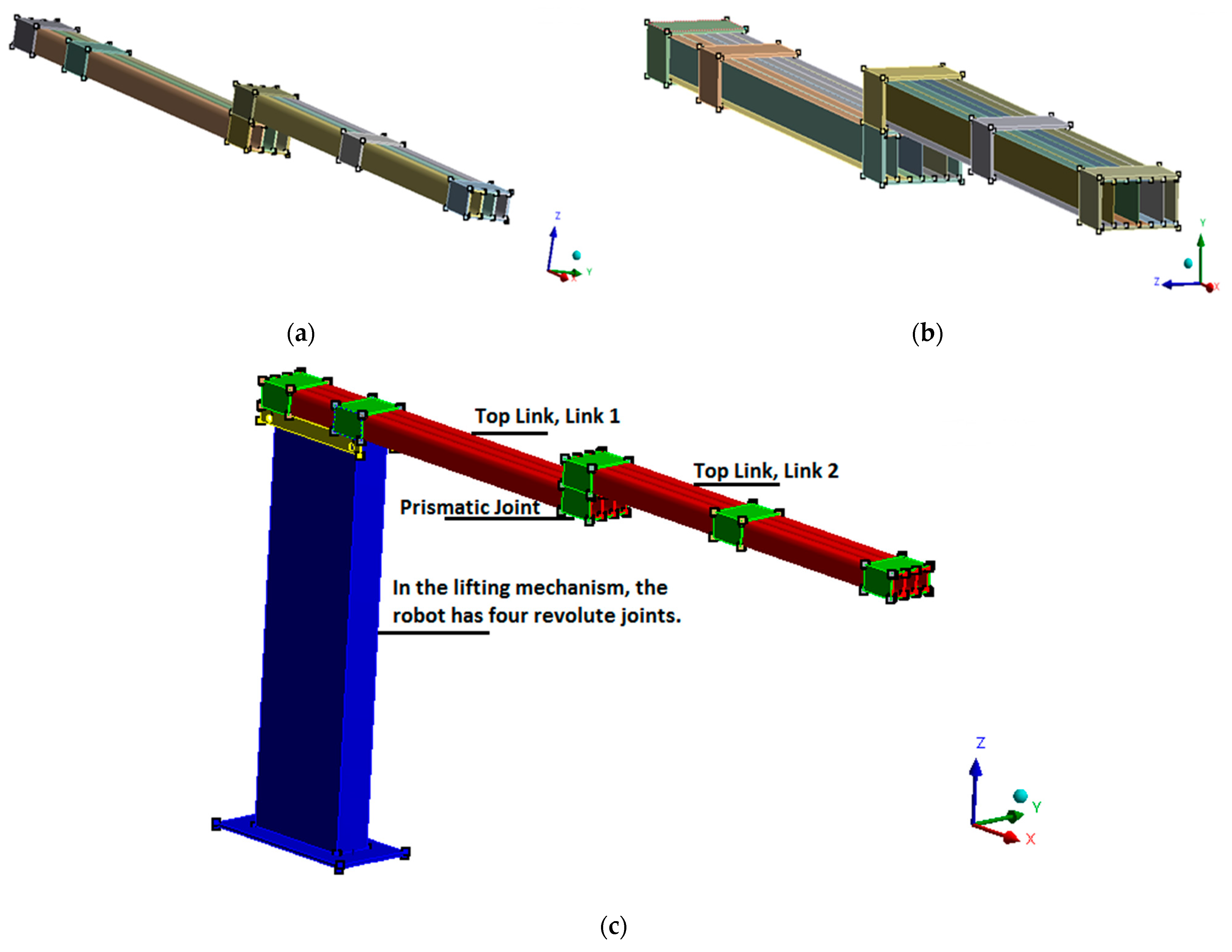
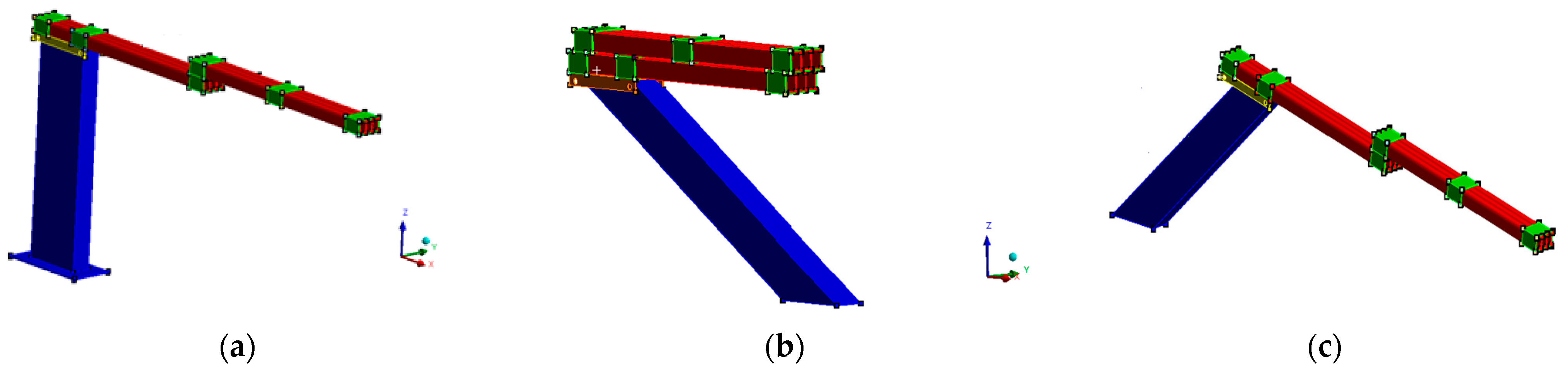
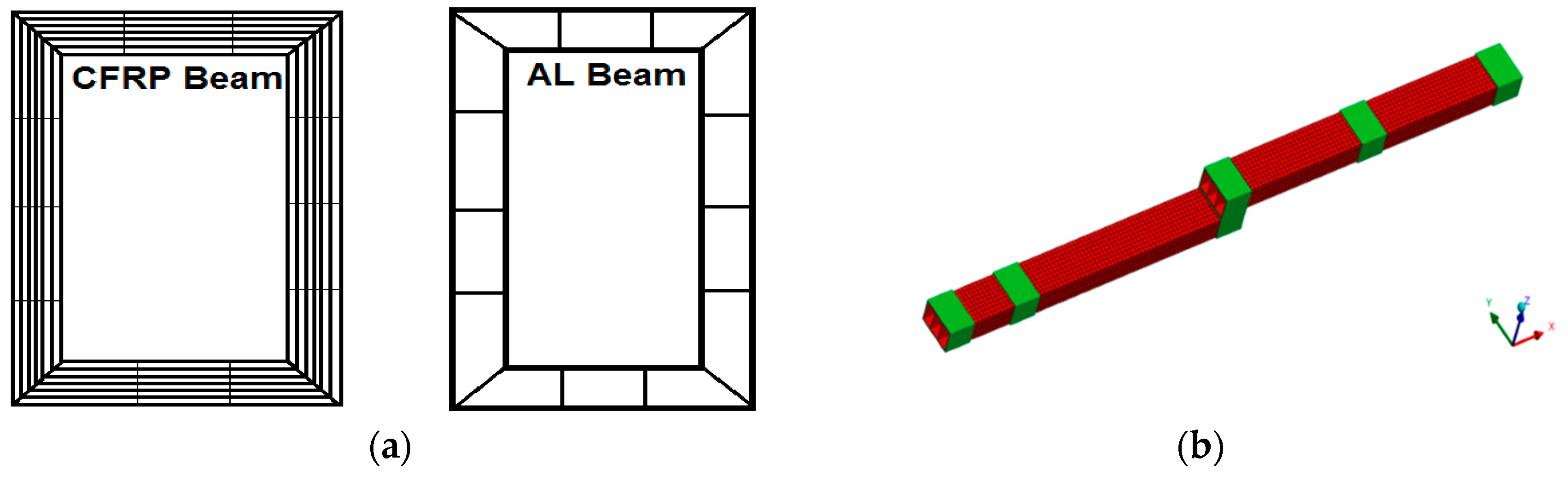
2. Robot Manipulator’s Composite Parts

The robot under consideration was a 5-DOF manipulator that was designed, built, and tested at the University of Saskatchewan for plant monitoring applications [21]. In Figure 1c, the robot is shown partially as it is being patented. This manipulator had four rotational joints and one prismatic joint. The robot’s top part was created from two links connected with a prismatic joint. Each link was about 1.2 m long and the robot’s fully extended configuration could reach up to about 3 m. Each of the two top links was made of three AA beams with a length of 1.2 m and a rectangular cross-section of 40 mm × 60 mm. The resulting multi-cell beam had dimensions of 60 mm × 120 mm. The robot’s end effector carried several sensors with a total payload mass capacity of about 20 kg. The robot’s vibration and tip (end effector) displacement affected the sensors’ measurement performance in terms of the photo quality and the collected data. To obtain a desired tip deflection and acceptable natural frequencies for vibration, some of the robot’s AA parts were replaced with composite parts. Two types of thin-walled laminated composite beams, specifically an I-beam and a rectangular tube, were used in the model. These parts were used to form three combined squared tubular sections and three combined I sections, referred to as “SSS” and “III”, respectively. These multi-cell beams were modeled with FEA using eight layups with CFRP materials. Figure 1a,b show the schematics of the “SSS” and “III” beams.
It should be noted that, while a nuts-and-bolts connection is ideal for connecting AA beams, for the assembly of composite CFRP beams this type of connection may degrade the beams’ quality and cause structural damage. Therefore, glue and AA clamps were used to assemble the CFRP beams. For simplification and modeling, other components such as motors were not included in the FEA.

3. Verifying the FE Model

The FE model results were verified and compared with the experimental results reported in [17]. The authors of [17] did a very good job of testing several CFRP beams and reporting their results. Since we do not currently have the facilities to conduct similar tests, we decided to rely on the academically reported and peer-reviewed results from [17]. In the near future, we plan to procure experimental facilities and conduct similar static tests, and add vibrational tests as well. For the vibrational tests, we plan to use several IMUs (inertia measurement units) to measure the accelerations in different locations of the manipulator that are induced by an impact or by continuous excitation signals to the base of the manipulator. Such a vibration test would reveal the natural frequencies and mode shapes of the manipulator. The experimental results reported in [17] are related to a three-point bending test on a composite beam. The strain values were measured using a strain gauge on a specimen with a symmetric layup created from eight 0° plies and two 90° plies ([0,0,0,0,90]S). To compare with the experimental results, a hollow square composite beam with dimensions of 40 × 60 mm and a length of 280 mm was modeled. The beam was created from ten layers with a total thickness of 2 mm. Figure 2 shows the three-point bending test schematic setup and the detailed mesh of the CFRP box with its supports.
Numerical modelling of the composite beams was performed using the commercial finite element analysis software ANSYS (FEA software, Canonsburg, PA, USA) [29]. Solid elements were used to mesh the composite beams. Specifically, Solid185 was selected for meshing the CFRP beam. This element is defined by eight nodes with three degrees of freedom at each node, specifically translations in the nodal x-, y-, and z-directions. The parts of the beam in contact with the supports were selected as the target surfaces and the top face of the supports was chosen as the contact surface. Conta174 and Targe170 were used for meshing the contact and target face. The connections between the supports and the beam were considered to be frictionless. A mesh convergence study was performed to verify the accuracy of the FEA, and the results are shown in Table A9. A remote point was defined at the top support to apply the load. Defining remote points in the selected parts allowed for the application of loading and displacement. The reference points inside the two bottom supports were fully constrained to limit their freedom in any direction. The load values in Table 1 were taken from the literature [17] and the material properties are given in Table A7. From Table 1, it can be seen that there is a good agreement between the FEA results and the experimental results from [17].

4. Effect of Layup on Mechanical Properties of Composite Parts

As mentioned in the Introduction, eight layups were selected to evaluate the effectiveness of CFRP beams in terms of the robot static and free-vibration performance. For this purpose, the effects of the layup on the mechanical properties of the CFRP beams were investigated by following the approaches of Moazed et al. [11] and Ding et al. [17]. These references investigated the role of the layup in the design of CFRP beams to meet high bending resistance and lightweight design criteria. In these studies, the effect of increasing the fiber direction in the angle-ply layups (L1 to L3 layups) [11] and adding plies with fibers at 45° and 90° (L4 to L8 layups) on the beam’s static and free-vibration performance [17] was studied. For the mentioned 5-DOF robot, the top link’s bending deflection had the greatest effect on the sensors’ stability; thus, calculating the equivalent Young’s elastic modulus ( E x ) in the longitudinal direction was of interest. To perform a more comprehensive analysis, the equivalent shear modulus ( G xy ) was also calculated. To calculate the elastic and shear moduli, Equations (1)–(3) were used [18].
[ a b b T d ] = [ A B B D ] 1
E x = | A 11 A 12 A 16 A 12 A 22 A 26 A 16 A 26 A 66 B 11 B 12 B 16 B 12 B 22 B 26 B 16 B 26 B 66 B 11 B 12 B 16 B 12 B 22 B 26 B 16 B 26 B 66 D 11 D 12 D 16 D 12 D 22 D 26 D 16 D 26 D 66 | | A 22 A 26 B 12 A 26 A 66 B 16 B 22 B 26 B 26 B 66 B 12 B 16 D 11 B 22 B 26 D 12 B 26 B 66 D 16 D 12 D 16 D 22 D 26 D 26 D 66 | 1 n . t
G xy = | A 11 A 12 A 16 A 12 A 22 A 26 A 16 A 26 A 66 B 11 B 12 B 16 B 12 B 22 B 26 B 16 B 26 B 66 B 11 B 12 B 16 B 12 B 22 B 26 B 16 B 26 B 66 D 11 D 12 D 16 D 12 D 22 D 26 D 16 D 26 D 66 | | A 11 A 12 B 11 A 12 A 22 B 12 B 12 B 16 B 22 B 26 B 11 B 12 D 11 B 12 B 22 D 12 B 16 B 26 D 16 D 12 D 16 D 22 D 26 D 26 D 66 | 1 n . t
where [A], [B], and [D] are the laminate extensional, coupling, and bending stiffness matrices, respectively, while [a], [b], and [d] refer to the laminate extensional, coupling, and bending compliance matrices, respectively. E x is the laminate equivalent of Young’s modulus in the longitudinal direction, G xy is the equivalent shear modulus, n is the number of layers, and t is the layer thickness. As mentioned in Section 2, square tubular sections and I sections were used to model the robot’s top links. The beam’s equivalent bending stiffness E I y y (and torsional stiffnesses, G I t ) was calculated using Equations (4) and (5) for the square beam and I-beam, respectively [14].
E I y y = b f ( a 11 ) f d 2 2 + 2 b f ( d 11 ) f + 2 b w 3 12 ( a 11 ) w   ,       G I t = 2 d f 2 d 2 ( a 66 ) f d f + ( a 66 ) w d
E I y y = b f ( a 11 ) f d 2 2 + 2 b f ( d 11 ) f + 2 b w 3 12 ( a 11 ) w
where E I y y is the equivalent bending stiffness about the Y-axis, a 11 is the laminate extensional compliance, a 66 is the laminate shear compliance, and d 11 is the laminate bending compliance, as shown in Equations (4) and (5). Figure 3 shows the geometrical details for the square and I-beams and a laminate schematic depicting the individual plies for L8 =   [ 0 2 / ± 45 / 90 ] s .
Table 2 displays the E x ,   G xy , and E I y y values for the CFRP beams with various layups, as well as for an AA beam. As shown in this table, the elastic module was ( E x = 71.0   GPa ) for the AA beam and ( G xy = 20.7   GPa ) for the shear model. The CFRP beams with the L1, L2, L4, L5, L7, and L8 layups had higher E x values than the AA beam, and the beams with the L3 and L6 layups had lower E x values than the AA beam. The CFRP beams with the L3 and L6 layups had a higher G xy than the AA beam and the beams with the other layups had lower shear moduli than the AA beam. Overall, the results indicated that increasing the fiber direction in an angle-ply layup and adding layers in fiber directions other than zero decreases the equivalent bending stiffness. Equations (1)–(5) and the parameter values used here were adopted from references [14,18].

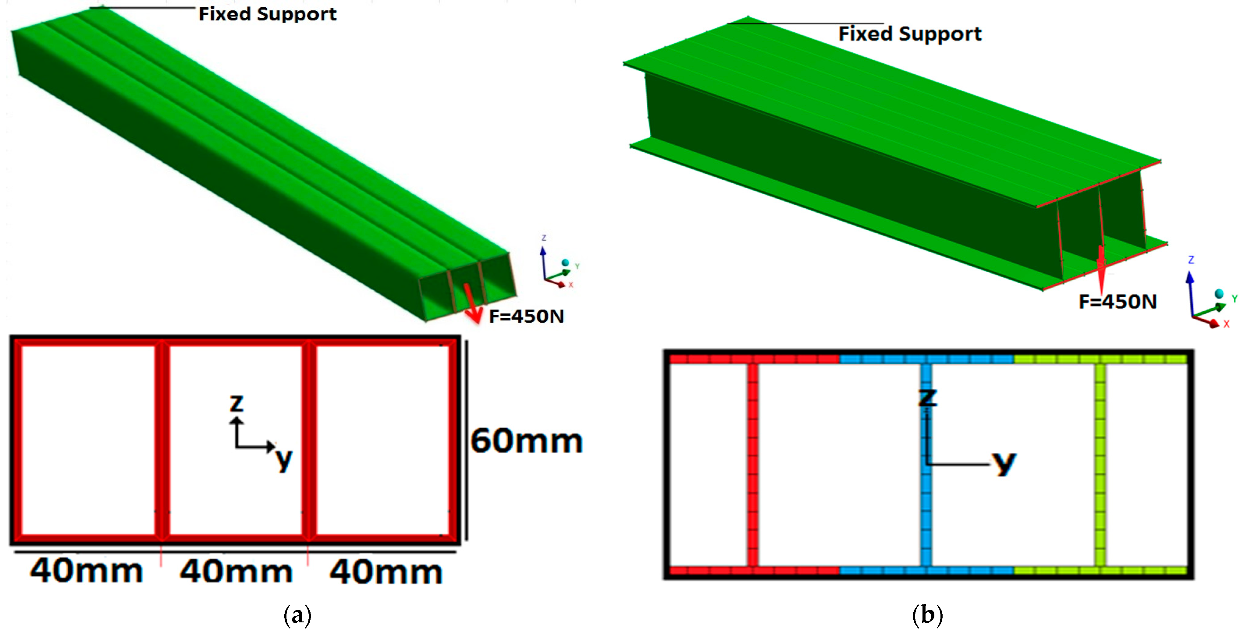
5. Effect of Layups on Beam Deflection

In this section, the effect of the layups on upper link deflection was determined using FE modelling. For verification purposes, the results obtained from FEA were compared with the analytical solution results. The FE model geometry, applied loading, and boundary conditions are shown in Figure 4. The cantilever beams shown in this figure were 1.2 m long and had cross-sectional dimensions of 120 mm × 60 mm. A concentrated load of 450 N in the z-direction was applied at the free end of the cantilever. The elements adopted were Solid185 and Solid186. These elements had three degrees of freedom at each node, specifically translations in the nodal x-, y-, and z-directions, and were either linear, i.e., defined by eight nodes (Solid-185), or were a higher order (i.e., quadratic) defined by twenty nodes (Solid-186). As a default in FE software, the CFRP beams were meshed with Solid185 elements, while the AA beams were meshed with Solid186 elements. The AA and CFRP material properties, as defined in Table A7 and Table A8, were assigned to these FE models.
The beam’s maximum deflection was calculated from Equation (6), for which the E I y y values are given in Table 2.
δ b = P L 3 3 E I y y
where δ b   is the maximum bending deflection in the z-direction, P is the applied force, L is the beam length, and E I y y is the equivalent bending stiffness. Table 3 shows the beam tip deflection for the different layups as calculated analytically and using FEA.
The AA “SSS” beam had a deflection ( δ b F E A ) of 6.34 mm and the CFRP “SSS” beams with the L1, L2, L4, L5, L7, and L8 layups had deflections lower than the AA beam. These deflections were 3.13, 4.93, 3.91, 4.89, 4.08, and 6.31 mm, respectively, as shown in Table 3. The CFRP beams with L3 and L6 layups had higher deflections than the AA beam. More specifically, the L1 layup, with ten 0° plies, as well as the L4 and L7 layups, with eight 0° plies, had the lowest deflections. The L3 and L6 layups, with ten 30° plies and six 45° plies, respectively, had the highest deflections, showing that adding layers with fibers in directions other than 0° will increase beam deflection. Similarly, the same trends were noted for the CFRP “III” beams. For the AA “III” beam, the tip deflection was 7.33 mm, versus 3.66, 5.81, 4.59, 5.75, and 4.81 mm for the L1, L2, L4, L5, and L7 layups, respectively, as shown in Table 3. Equation (7) was used to calculate the differences in Table 3:
Difference % = | δ b F E A δ b ( 6 ) δ b F E A × 100 |
The values for the difference percentages provided in Table 3 ranged from 0% to 5.63%. These differences were due to the fact that the analytical solution did not take into account the effects of shear and warping deformations. As mentioned in Section 4, the square beam was 1.17 times stiffer than the I-beam, and Equation (8) was used to express the relationship between the “SSS” and “III” beams. For example, the relationship between the beams in the L1 layup was as follows:
( E I S S S E I I I I ) Analytical = ( δ I I I δ S S S ) FEA 82282.5 69813.9 = 3.66   mm 3.13   mm 1.17
where E I S S S and δ S S S are the equivalent bending stiffness and deflection values for the “SSS” beam with the L1 layup, respectively, and E I I I I and δ I I I are the equivalent bending stiffness and deflection values for the “III” beam with the L1 layup, respectively. In addition to the comparisons between the deflection of the AA and CFRP beams, the AA “SSS” and “III” beams had masses of 3.81 kg and 2.73 kg, whereas the CFRP “SSS” and “III” beams had masses of 2.19 kg and 1.56 kg, respectively. These results show that the “SSS” beams were 1.17 times stiffer and 1.40 times heavier than the “III” beams. The results presented in this section indicate that using CFRP beams in a robot’s upper link structure could decrease the tip deflection and mass of the structure. See the discussions before Equation (7).

6. Failure Index

The aim here was to determine the first ply failure of the CFRP beams, specifically under bending. When bending is applied to a CFRP beam, all three stress components (tensile, compressive, and shear) are induced (see Appendix A.2). The allowable strength (or failure stress) is the combined effect of these stress components. Therefore, it was assumed that failure would happen in the CFRP beams when the first ply reached the allowable strength. Two failure criteria for fiber-reinforced materials, specifically Tsai–Hill and Tsai–Wu, were used to determine the failure indices [18].
In order to use a failure criterion, it is necessary to calculate the stress components in the fiber direction or a local coordinate system ( 1 ,   2 ), as shown in Figure 5. For this purpose, the analytical method from [14] was adopted; the details of the stress analysis are presented in Appendix A.1. Also, for verification purposes, the results obtained analytically here were compared with the FEA results. This comparison is reported in Appendix A.2.
The first failure criterion applied was Tsai–Hill, which was developed based on von Mises–Henky’s distortion energy theory. The Tsai–Hill failure criterion for composites is as follows [18]:
σ 1 2 F 1 2 + σ 2 2 F 2 2 ( σ 1 σ 2 ) F 1 2 + σ 12 2 F 6 2 = F I
where FI is the failure index, σ 1 is the ply’s longitudinal stress in the fiber direction (1 in Figure 5), σ 2 is the ply’s transverse stress (2 in Figure 5), and σ 12 is the ply’s shear stress in local coordinates (1, 2) as shown in Figure 5. Here, F 1 and F 2 refer to the tensile yield strengths in directions 1 and 2, respectively, and F 6 is the shear strength. To account for the difference between the tensile and compressive strengths, the modified Tsai–Hill approach was proposed, where F 1 t , F 1 c , F 2 t , and F 2 c are the longitudinal tensile and compressive strengths, respectively:
F 1 = { F 1 t   w h e n   σ 1 > 0   F 1 c   w h e n   σ 1 < 0
F 2 = { F 2 t   w h e n   σ 2 > 0   F 2 c   w h e n   σ 2 < 0
An alternative approach was to use the Tsai–Wu criterion as expressed below:
f 11 σ 1 2 + f 22 σ 2 2 + 2 f 12 ( σ 1 σ 2 ) + f 66 σ 12 2 + f 1 σ 1 + f 2 σ 2 = F I
where f 1 = 1 F 1 t 1 F 1 c , f 2 = 1 F 2 t 1 F 2 c , f 11 = 1 F 1 t F 1 c ,   f 22 = 1 F 2 t F 2 c ,   f 12 = 0.5 f 11 f 22   , and f 66 = 1 F 6 2 are the coefficients obtained from the shearing and uniaxial strength tests [18]. Here, f 12 is a coefficient which represents a biaxial composite beam strength in the longitudinal and transverse directions. The main difference between these criteria is that the Tsai–Wu criterion accounts for the interactions and differences between stresses, but requires biaxial testing to define f 12 . Using the failure index defined in Equations (9) and (12), a safety ratio (SR) was defined as shown below:
S R = 1 F I  
The safety ratio is a multiplier that determines when a failure occurs for a given load. For example, a safety ratio of 1.4 indicates that a failure will occur in a composite structure if the applied load, or moment, is increased by 40%.
As shown in Figure 6, the “SSS” and “III” beams were modelled using the FEA software, and a moment (My = 3500 Nm) was applied at the free end of the beams about the Y-axis to calculate the load-carrying capacity of the manipulator. The moment value was determined based on the manipulator’s fully extended operational configuration: when the distance between the manipulator’s end effector and its base was about 3 m in the x-direction, and the end effector’s mass was about 20 kg. In order for one of the layups to meet a failure criterion, the moment value employed in the strength analysis was selected to be nearly six times this magnitude (e.g., the “III” beam with the L3 layup). The FEA results were reported for a point in the middle of the beam, at a sufficient distance away from the boundary condition effects.
Table 4 and Table 5 compare the plies with the minimum safety ratios in each layup, where S R T W a n a and S R T H a n a refer to the analytical Tsai–Wu and Tsai–Hill safety ratios, respectively; the methods are explained in Appendix A.1. The analytical results obtained were compared with the FEA results, as presented in Table A1, Table A2, Table A3 and Table A4 in Appendix A.2. For comparison, the von Mises stress was used in the FEA software to calculate the AA beam’s safety ratio. Also, since the beam was under moment loading about the Y-axis, the top and bottom flanges (layers) of the beam were under tension and compression, respectively.
From Table 4, the AA “SSS” and “III” beam safety ratios were 1.55 and 1.36, respectively. For the “SSS” and “III” beams with the L1, L2, L3, and L6 layups, the first ply (or the beams’ outer ply) had the lowest SR; this can be considered failure initiation under tension. In addition, for the “SSS” and “III” beams with the L4, L7, and L8 layups, the fifth ply (from the beams’ outer ply) had the lowest SR. In beams with the L5 layup, the third ply (from the beams’ outer ply) had the lowest SR. Furthermore, as shown in Table 4 for the “SSS” and “III” beams under tension, the safety ratios for L1 and L3 decreased as the fiber direction changed from 0° to 30°; also, the layups L1, with ten plies at 0°, and L3, with ten plies at 30°, had the highest and lowest safety ratios among all eight layups, respectively. The safety ratio dropped incrementally for the L1, L4, L5, and L6 layups, for which the number of 0°plies decreased incrementally from ten to four. When comparing L1 and L4 ([ 0 4 / ± 45 / 0 4 ] ), with two 45 ° plies, and L7 ( [ 0 , 0 , 0 , 0 , 90 ] s ) , with two 90 ° plies, the safety ratio increased and subsequently decreased. Furthermore, when comparing L7 and L8 layups, both with an equal number of 90° plies, but with L8 having additional 45° plies, L8 had a decreased safety ratio. Overall, the results indicated that, for the beam under tension, increasing the fiber direction from 0° to 30° in angle-ply layups, decreasing the number of 0° plies, and adding ± 45 ° and 90° plies decreased the load-carrying capacity (or SR) for both the “SSS” and “III” beams.
Table 5 shows a comparison of plies with the minimum safety ratio in “SSS” and “III” beams when the beam’s flange (layer) is under compression. For the “SSS” and “III” beams with the L1, L2, L3, L4, L5, L7, and L8 layups, the first ply (or the beams’ outer ply) had the lowest SR, while in beams with L6 layup, the third ply (from the beams’ outer ply) had the lowest SR. Comparing Tsai–Wu and Tsai–Hill criteria showed that, for the L1 layup with all plies at 0°, both criteria estimated a similar safety ratio; the SR differed for cases where the stress interactions were higher because of fibers that were oriented in a direction other than zero.

7. Effect of Layup on Composite Beam’s Natural Frequency

This section investigates the effects of different layups on the natural frequencies of the AA and CFRP “SSS” and “III” beams. To calculate the natural frequencies in the composite beams, the two methods reported in [14] were adopted. The first method is based on classic beam theory (CBT) and the second method is based on first shear deformation theory (FSDT). To consider the effect of shear deformation, an approximate method was used to calculate the fundamental natural frequency. Equations (14)–(17) were used to calculate the fundamental natural frequency for a cantilever beam. As shown in Figure 1, the multi-cell-section beams were symmetric about the Z-axis. The beam’s fundamental natural frequency in the xz-plane, due to lateral vibration, is given by the following [14,28]:
w b = E I y y . ( 1.875 ) 4 ρ . L 4
w s = S ZZ . ( π 2 ) 2 ρ . L 2
1 w y 2 = 1 w b 2 + 1 w s 2
f = w y 2 π
In Equation (14), w b   is the natural frequency of lateral vibration in the xz-plane for a cantilever beam undergoing bending deformation, E I y y is the equivalent bending stiffness about the Y-axis, ρ is the mass per unit length, and L is the beam length. In Equation (15), w s is the natural frequency of the beam due to tortional motion (considering shear deformation), where S ZZ is the equivalent shear stiffness, as defined in Appendix A.3. In Equation (16), w y is the approximate combined natural frequency of vibration in the xz-plane. This solution was obtained from Föpplms theorem [14], developed for estimating the buckling load for elastic structures. Table 6 shows the fundamental natural frequencies for AA and the eight layups discussed earlier for the “SSS” and “III” section beams. The difference was calculated using Equation (18). Here, f b C B T was obtained from Equations (14) and (17), and f y F S D T was obtained using Equations (16) and (17), respectively. Note that w y gives the frequency in rad/s, while f is the frequency in Hz. Because the manipulator top links were made out of three beams, the E I y y values in Table 6 are three times higher than the E I y y values found in Table 2.
Difference = | f b F E A f y F S D T f b F E A | × 100
From Equation (14), it can be seen that the angular natural frequency is proportional to the beam’s equivalent bending stiffness and inversely proportional to the beam’s mass, as expected. When comparing the natural frequencies of the “III” and “SSS” section beams, the “III” section beam with the lower mass had a greater natural frequency than the “SSS” section beam. Also, among L1 to L8, the L1 layup, with ten 0° plies, and the L4 and L7 layups, with eight 0° plies, had the highest fundamental natural frequencies. From Table 6, it can be observed that CFRP beams with all eight layups had higher fundamental natural frequencies than the AA beam. By comparing the CBT and FSDT results, it can be observed that the CBT method overestimated the natural frequencies and the FSDT method underestimated the natural frequencies when compared with the FEA results. The f y F S D T and f b F E A results were in a good agreement, with a maximum difference of less than 3%.

8. Selecting the Best Layup for Composite Parts

The next stage was to select the ideal layup and cross-section for the manipulator’s composite parts after calculating the deflection, load capacity, and natural frequency. The “SSS” beam had a lower deflection and a higher safety ratio, whereas the “III” beam had a higher natural frequency and a lower weight. As demonstrated in [11], the “SSS” beam had a smaller angle of twist under torsional loading than the “III” beam. Therefore, both cross-sections were suitable for the manipulator’s top link. In this study, the “SSS” beam was selected to model the robot’s top link in order to perform a modal analysis on the 5-DOF robot. Also, the L1 ( [ 0 , 0 , 0 , 0 , 0 ] s ), L4 [ 0 4 / ± 45 / 0 4 ] , and L7 ( [ 0 , 0 , 0 , 0 , 90 ] s ) layups were found to have the best values in terms of the minimum deflection, the plies with the highest minimum safety ratio, and the highest natural frequencies, so these three layups were selected for this analysis.
Considering the “SSS” section, the L1 layup, with ten 0° plies, had the lowest tip deflection   ( δ b = 3.15   mm ) , the highest safety ratio ( S R T W = 6.57 ) , and the highest fundamental natural frequency ( f y F S D T   = 78.4 Hz). Table 7 shows that, in terms of deflection and natural frequency, L4 and L7 had similar values, but the L7 safety ratio under compression was 52% greater than the L4 safety ratio. Considering the mentioned specifications, L7, with two 90° plies and eight 0° plies, and L1, with ten 0° plies, could be ideal layups for creating the manipulator’s composite parts. In the following section, the CFRP “SSS” beam with the [ 0 , 0 , 0 , 0 , 90 ] s layup was used to perform the modal analysis on the CFRP 5-DOF manipulator in order to estimate possible improvements in terms of the structural mass and the fundamental natural frequency compared with the AA 5-DOF manipulator.

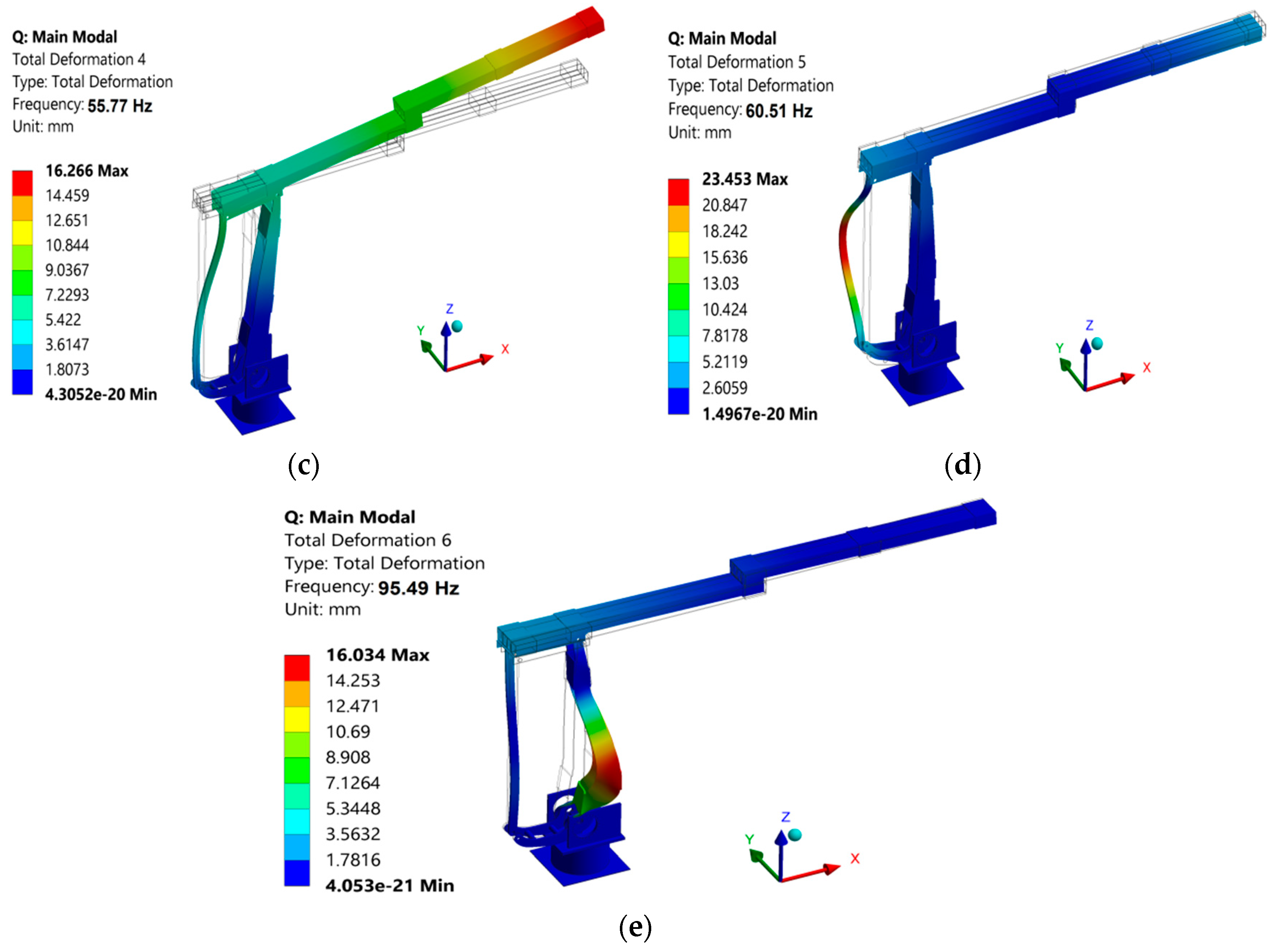
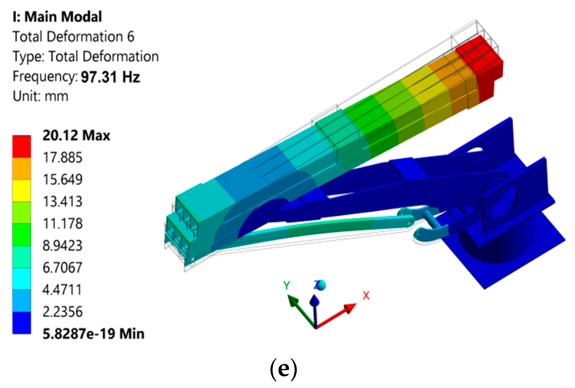
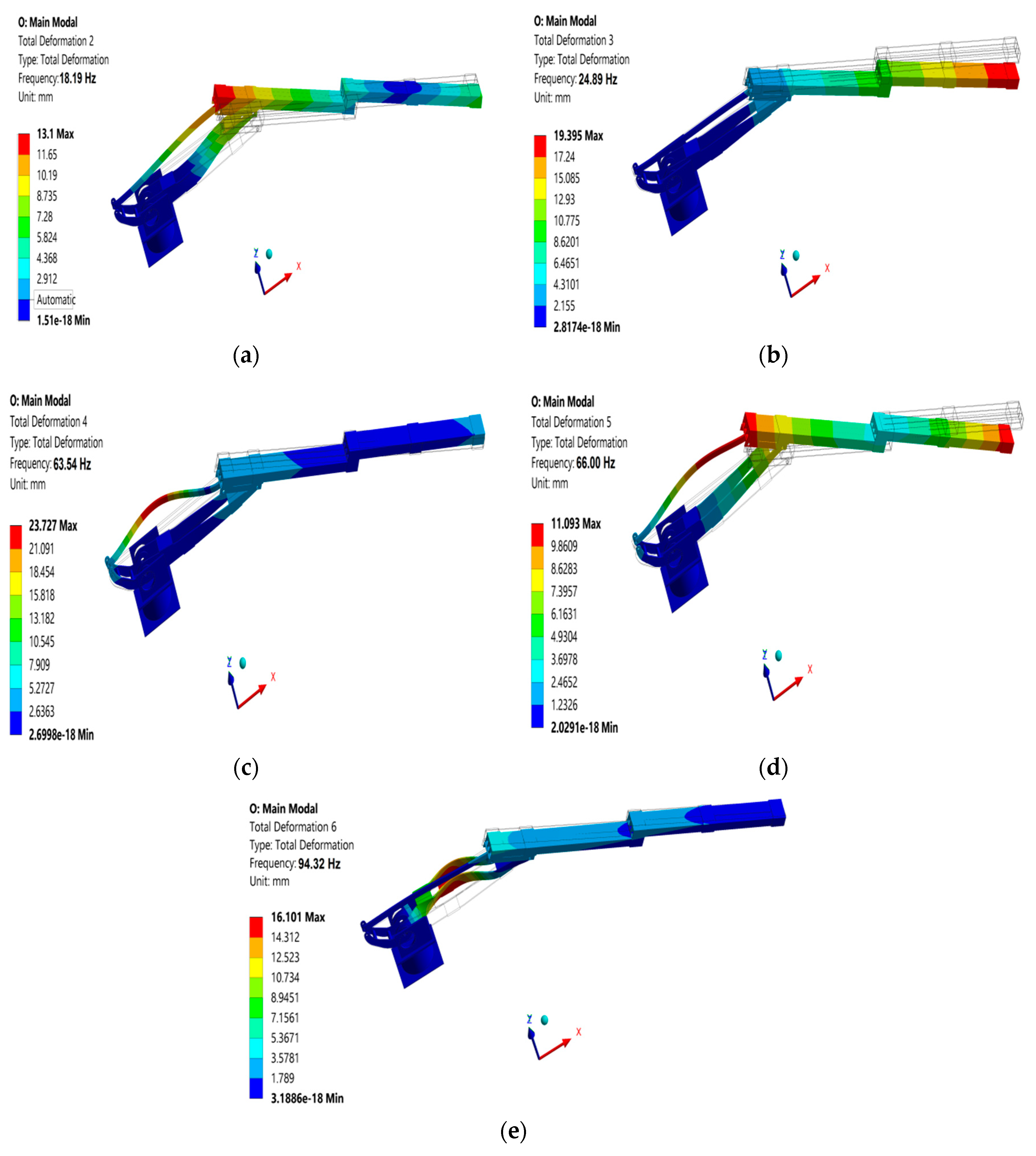
9. Modal Analysis of the Manipulator

In this section, three configurations for the 5-DOF manipulator, which are common operating conditions, were considered for the modal analysis. Figure 7 shows these three configurations. The aim here was to determine the natural frequencies and their corresponding mode shapes. From the three configurations presented, the fully extended Configuration 3 (Figure 7c) was the most important one, as it was the manipulator’s working (crop monitoring) pose. Configuration 2 was the manipulator’s transport mode (Figure 7b) and Configuration 1 (Figure 7a) was the manipulator’s occasional use pose. In Figure 7, the green parts are AA clamps, and all members are in the xz-plane.
The original manipulator [21] base was made out of steel and its top link was created from AA. The aim here was to investigate the impact of using CFRP for the top links on the manipulator’s free vibration via modal analysis. For this purpose, the robot’s top links were replaced with thin-walled laminated CFRP beams. Figure 8a,b depict the top link models made of AA and CFRP materials, respectively. The Solid186, CONTA174, and TARGE170 element types were used to mesh the AA model, and the Solid185, CONTA174, and TARGE170 element types were used to mesh the CFRP model. To mesh the CFRP “SSS” section top link, 104,912 elements were used, and to mesh the AA “SSS” section top link, 26,242 elements were used. The difference in the total number of elements was due to the fact that the composite beam, with a total thickness of 2 mm, was formed by stacking 10 CFRP layers, each with a thickness of 0.2 mm (Figure 8a). Each layer was meshed separately with a mesh-seed equal to 0.2 mm. The AA beam was defined with a thickness of 2 mm and a beam cross-section meshed with a mesh-seed that was equal to the cross-sectional thickness of close to 2 mm. Comparing the CFRP “SSS” section beam with the AA beam, the element ratio was 10:1 in the direction of the thickness. In addition, the joint between the beams was modeled as a fixed joint.
In the final step, the CFRP and AA beams were incorporated into the rest of the manipulator with a steel body. Table 8 shows the first six natural frequencies of the AA and composite CFRP manipulators. Figure 9 and Figure 10 show the first mode shape for the three configurations. Higher mode shapes are given in Appendix C.
The difference percentages in Table 8 were computed using Equation (19), where w C F R P is the natural frequency of the CFRP manipulator and w A A is the natural frequency of the AA manipulator.
Difference = | w A A w C F R P w A A | × 100
As mentioned earlier, the third configuration was the most important pose. Looking at the natural frequencies in Table 8 and their mode shapes, the first natural frequency of the CFRP robot was the bending vibration around the Z-axis in the xy-plane, in which the top links had the largest contribution. The second natural frequency was a mixed vibration mode formed by two vibration types: first, the rotational vibration around the Z-axis; and second, the bending around the Y-axis. The third and fourth natural frequencies were the bending vibrations around the Y-axis, with the top links having the largest displacement. Also, from the mode shapes in Appendix C, it can be seen that the robot’s top links had the largest contribution among the robot components from the first to the fourth natural frequencies. Thus, the top links were the parts that were prone to vibration.
Table 8 shows the improvement in the fundamental natural frequencies achieved by using CFRP beams in the manipulator’s structure. In the third configuration, the natural frequencies from the first mode to the third mode increased by 19.3%, 6.43%, and 19.8%, respectively. Furthermore, the CFRP manipulator’s mass was 51.8 kg, while the AA robot’s mass was 55.2 kg, indicating a 6.15% difference in the structural mass. Overall, the natural frequencies and mode shapes depended on the mass and stiffness distributions of the structure. The structure with the higher stiffness and lower mass had the highest natural frequency. Therefore, the analysis above indicates that it is critical to decrease the top link mass as much as possible while meeting the load-carrying capacity requirements.

10. Conclusions

This study investigated the effects of thin-walled laminated CFRP beams on the static and free-vibration performance of a 5-DOF manipulator. The effects of using composite materials were considered in terms of the fundamental natural frequency, load-carrying capacity, and structural mass, and were compared with the 5-DOF aluminum alloy (AA) manipulator. It was shown how the cross-sections and layups can affect these parameters. For this purpose, AA and CFRP beams with eight layups were used to determine the structural efficiency of composite materials for a 5-DOF manipulator.
A beam safety ratio was introduced using the Tsai–Wu and Tsai–Hill failure criteria. The fundamental natural frequencies were determined using the classical beam and shear deformation theories. Three-dimensional finite element models using linear and quadratic solid elements were employed, and results were compared with the analytical results. Three working configurations of the 5-DOF manipulator were investigated using a modal analysis, and the results were reported for the CFRP and AA models. Overall, this study showed that changing the fiber direction from 90° to 0° in an angle-ply layup and adding more 0° plies while keeping the overall numbers of layers the same decreased the deflection and increased the natural frequency and load-carrying capacity. Replacing parts of an AA manipulator with CFRP can increase the fundamental natural frequencies by 19% and can decrease the structure mass by about 6.15%. See the discussions in Section 5 for details. It was shown that CFRP can be used to improve the performance of a manipulator made of AA, without compromising its performance or structural integrity and while producing moderate gains in efficiency, i.e., increasing the natural frequency, which was desirable for this application.

Author Contributions

Conceptualization, R.F.; formal analysis, M.A.K.; funding acquisition, R.F.; investigation, M.A.K., R.F. and R.M.; methodology, M.A.K., R.F. and R.M.; software, M.A.K.; supervision, R.F. and R.M.; validation, M.A.K.; writing—review and editing, R.F. and R.M. All authors have read and agreed to the published version of the manuscript.

Funding

Financial support for this work was provided by NSERC through a grant from the Canada First Research Excellence Fund (CFREF) via the Global Institute for Food Security (GIFS), the University of Saskatchewan, Canada. Funding was also provided by an NSERC-CRD grant.

Limitation

Although the research presented here could be extended to other serial-parallel manipulators, the results should be carefully viewed when extending to other robotic arms. The research presented here is for a 5-DOF serial-parallel manipulator with its lower part (two links) made of aluminum alloy and its upper part (three links) made of CFRP. Composite materials are more difficult to fabricate and almost impossible to machine.

Informed Consent Statement

Not applicable.

Acknowledgments

This research was conducted in the robotics laboratory at the University of Saskatchewan. The role of other lab members, especially QianWei Zhang, Hedieh Badkoobehhezaveh, Joshua Cote, and Majid KhakPour, in the development and testing of the AA manipulator is gratefully acknowledged. Also, useful comments from James Johnston, Duncan Cree, and Leon Wegner in improving the presentation of this manuscript is gratefully acknowledged.

Conflicts of Interest

The authors declare no conflict of interest.

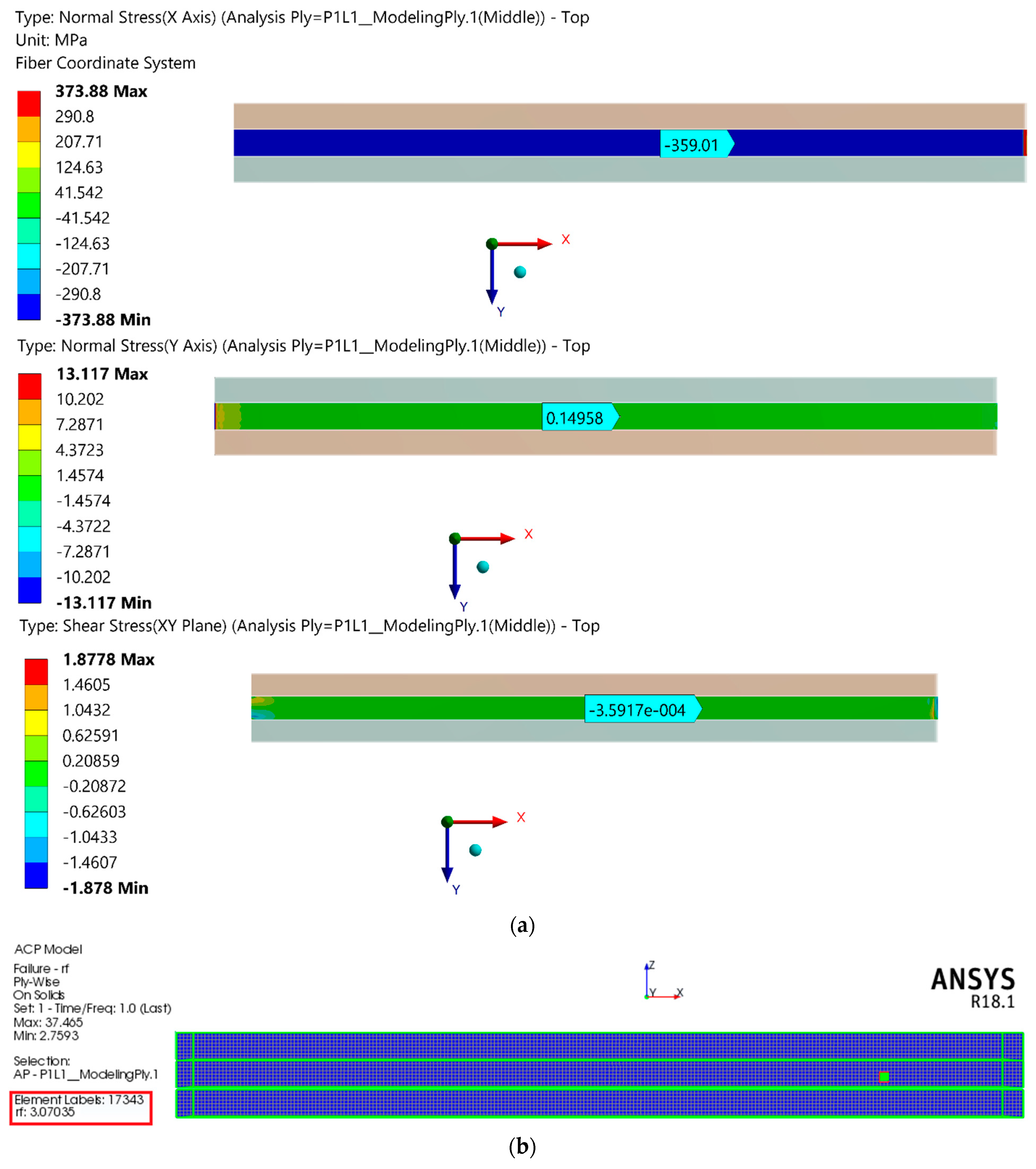
Appendix A. Detail of Stress Analysis and Verification for Laminated Composite Beam

Appendix A.1 and Appendix A.2 include the details on the stress analysis calculations and verification for Section 6. The square beam and I-beam equivalent shear stiffness equations, which were used in Section 7, are presented in Appendix A.3 and Appendix A.4, which show the calculation steps related to the composite beam’s equivalent bending and shear stiffness.

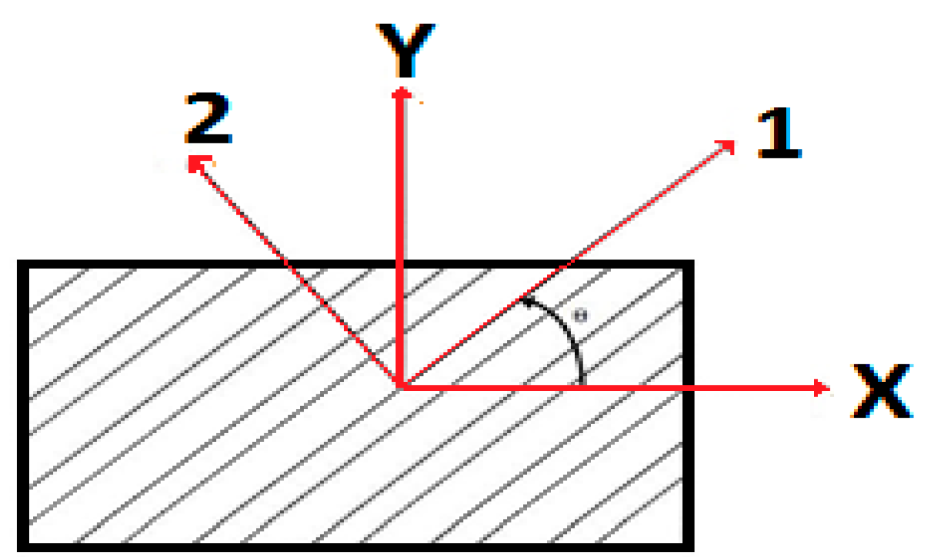
Appendix A.1. Stress Analysis of Laminated Composite Beam Details

To calculate the stress and strain components for the laminated composite beams, the method in [14] was used, as described below:
Using the classical laminate theory, the laminate stiffness and compliance matrix were calculated. In Equations (A1) to (A2), Aij is the laminate in-plane stiffness that relates the in-plane forces N x , N y , and N x y to the in-plane deformations ε x 0 , ε y 0 , and γ x y 0 . Dij is the bending stiffness that relates the moments M x , M y , and M x y to the curvatures K x , K y , and K x y . Bij is the in-plane coupling stiffness.
[ N x N y N x y M x M y M x y ] = [ A 11 A 12 A 16 A 12 A 22 A 26 A 16 A 26 A 66 B 11 B 12 B 16 B 12 B 22 B 26 B 16 B 26 B 66 B 11 B 12 B 16 B 12 B 22 B 26 B 16 B 26 B 66 D 11 D 12 D 16 D 12 D 22 D 26 D 16 D 26 D 66 ] [ ε x 0 ε y 0 γ x y 0 k x k y k x y ]
[ ε x 0 ε y 0 γ x y 0 k x k y k x y ] = [ a 11 a 12 a 16 a 12 a 22 a 26 a 16 a 26 a 66 b 11 b 12 b 16 b 12 b 22 b 26 b 16 b 26 b 66 b 11 b 12 b 16 b 12 b 22 b 26 b 16 b 26 b 66 d 11 d 12 d 16 d 12 d 22 d 26 d 16 d 26 d 66 ] [ N x N y N x y M x M y M x y ]
Thin-walled laminated beams are created from a number of segments. Using the below equation, the beam’s equivalent stiffness and compliance matrices were calculated. In Equations (A3) and (A4), R k and O k are the stiffness matrix components of each segment of a thin-walled beam; R k is the transformation matrix, which transforms the wall segment geometry to the global coordinate system; O k is the wall segment stiffness matrix component; and the index k refers to the wall segment number.
[ R k ] = [ 1 0 0 0   z k c o s α k s i n α k 0   y k s i n α k c o s α k 0   0 0 0 1 ]
[ O k ] = 1 b k [ a 11 0 0 0   0 d 11 0 d 13 2   0 0 12 A 11 b k 2 0   0 d 13 2 0 d 33 4 ]
The total stiffness matrix of the beam [P] is given by Equation (A5):
[ P ] = K = 1 n [ R k ] [ R k ] T [ O k ] 1    
The compliance matrix of the beam [W] is given by the below equation:
[ W ] = [ P ] 1
By substituting the obtained compliance matrix into Equation (A7), the beam’s axial and bending strain components could be calculated as shown below:
[ ε x 0 ε y 0 γ x y 0 k x k y k x y ] = W [ N x N y N x y M x M y M x y ]
[ ε x ε y γ x y ] = [ ε x 0 ε y 0 γ x y 0 ] + z k [ k x k y k x y ]
[ σ x σ y σ x y ] = [ Q ¯ 11 Q ¯ 12 Q ¯ 16 Q ¯ 12 Q ¯ 22 Q ¯ 26 Q ¯ 16 Q ¯ 26 Q ¯ 66 ]   [ ε x ε y γ x y ]

Appendix A.2. Comparison of Analytical Safety Ratios with FEA Results

The analytically estimated safety ratios were compared to the FEA results in this appendix (related to Section 6). In Table A1, Table A2, Table A3 and Table A4, σ 1 ,   σ 2 ,   and   σ 12   are local stress components that were determined analytically. It should be noted that the FEA results were reported for a point in the middle of the beam, at a sufficient distance away from the effects of boundary conditions. Table A1 and Table A3 show the safety ratios and stress components for a flange under tension for the “SSS” and “III” beams, while Table A2 and Table A4 show the safety ratios and stress components for a flange under compression for the “SSS” and “III” beams. In the below tables, S R T W a n a and S R T H a n a refer to the analytical safety ratios calculated using the Tsai–Wu and Tsai–Hill methods, respectively, while S R T W F E A and S R T H F E A are the FEA safety ratios calculated using the Tsai–Wu and Tsai–Hill methods, respectively.
Table A1. Comparison of plies with minimum safety ratios (SRs) for the “SSS” beam (flange under tension; stress values are in MPa); see Figure 3c for a laminate stacking sequence sample.
LayupPly No. (Angle) σ 1   (MPa) σ 2   (MPa) σ 12 ( MPa ) S R T W a n a S R T W F E A S R T H a n a S R T H F E A
L1Ply 1 (0°)1670011.310.411.310.4
L2Ply 1 (20°)182−14.7−13.04.514.274.264.02
L3Ply 1 (30°)190−23.1−35.02.182.061.891.80
L4Ply 5 (45°)4403.44−10.06.365.856.395.88
L5Ply 3 (45°)41.83.43−13.74.824.464.914.54
L6Ply 1 (45°)41.14.23−19.83.363.153.473.22
L7Ply 5 (90°)−12.412.403.993.684.103.79
L8Ply 5 (90°)−96.218.502.352.142.662.42
Table A2. Comparison of plies with minimum safety ratios (SRs) for the “SSS” beam (flange under compression; stress values are in MPa); see Figure 3c for a laminate stacking sequence sample.
LayupPly No. (Angle) σ 1   (MPa) σ 2   (MPa) σ 12 ( MPa ) S R T W a n a S R T W F E A S R T H a n a S R T H F E A
L1Ply 1 (0°)−167006.576.046.576.04
L2Ply 1 (20°)−18114.612.92.142.012.622.44
L3Ply 1 (30°)−19023.134.91.231.161.451.38
L4Ply 1 (0°)−2003.22−0.464.344.055.134.77
L5Ply 1 (0°)−2545.8303.122.943.833.58
L6Ply 3 (0°)−3459.210.272.202.052.732.54
L7Ply 1 (0°)−206−3.0406.616.025.334.93
L8Ply 1 (0°)−3310.0403.303.063.323.06
Table A3. Comparison of plies with minimum safety ratios (SRs) for the “III” beam (flange under tension; stress values are in MPa); see Figure 3c for a laminate stacking sequence sample.
LayupPly No. (Angle) σ 1   (MPa) σ 2   (MPa) σ 12 ( MPa ) S R T W a n a S R T W F E A S R T H a n a S R T H F E A
L1Ply 1 (0°)202009.398.899.398.89
L2Ply 1 (20°)219−17.7−15.63.733.323.533.14
L3Ply 1 (30°)229−27.842.21.801.631.561.42
L4Ply 5 (45°)49.74.3112.15.214.945.254.97
L5Ply 3 (45°)50.74.13−16.63.993.754.063.83
L6Ply 1 (45°)49.75.1123.92.852.652.892.71
L7Ply 5 (90°)−1514.903.303.133.393.19
L8Ply 5 (90°)−11622.301.941.842.202.07
Table A4. Comparison of plies with minimum safety ratios (SRs) for the “III” beam (flange under compression; stress values are in MPa); see Figure 3c for a laminate stacking sequence sample.
LayupPly No. (Angle) σ 1   (MPa) σ 2   (MPa) σ 12 ( MPa ) S R T W a n a S R T W F E A S R T H a n a S R T H F E A
L1Ply 1 (0°)−202005.435.145.435.14
L2Ply 1 (20°)−21917.715.71.771.552.171.88
L3Ply 1 (30°)−22927.842.21.020.911.201.06
L4Ply 1 (0°)−2423.89−0.563.593.214.253.90
L5Ply 1 (0°)−3077.040.022.592.313.172.88
L6Ply 3 (0°)−41711.10.321.811.712.262.13
L7Ply 1 (0°)−248−3.6705.485.144.414.11
L8Ply 1 (0°)−4000.040.032.722.632.732.59

Appendix A.3. Shear Compliances and Stiffness Equations for Square and I-Beams

Related to Section 4 and Section 7, Equations (A10) and (A11) can be used to calculate the square beam and I-beam equivalent shear compliances ( s ZZ ^ ), respectively. In Equation (A12), S ZZ is the beam’s equivalent shear stiffness, which is equal to the inverse of s ZZ ^ .
s ZZ ^ = a 66 2 d + a 66 . d f 6 d 2 ( 1 + a 11 d 3 a 11 d f ) 2
s ZZ ^ = a 66 d + a 66 . b f 6 d 2 ( 1 + a 11 d 6 a 11 b f ) 2
S ZZ = [ s ZZ ^ ] 1

Appendix A.4. Details on Calculating the Equivalent Bending and Shear Stiffness of a Composite Beam

This section explains the steps for calculating the equivalent bending and shear stiffness of a CFRP square beam, which are related to Section 4 and Section 7. The compliance matrix components for a laminate with a [0/0/0/0/0]s layup are shown in Table A5.
Using the data in Table A5 and Table A6 and Equation (4), the equivalent bending stiffness ( E I y y ) for a square beam is 27,427.58 (N·m2).
Table A5. Laminate with [0/0/0/0/0]s layup compliance components.
a 11   ( m m N ) a 66   ( m m N ) d 11   ( 1 N ·   m m )
3.52 × 10⁻⁶ 1.08 × 10⁻⁴ 1.05 × 10⁻⁵
Table A6. Square beam geometrical dimensions (mm) (Note: the cross-sectional details are shown in Figure 3).
Layupdbwbfdf
[0/0/0/0/0]s58564038
Similarly, the square beam equivalent shear compliance and stiffness can be determined using Equations (A10) and (A12). The equivalent shear compliance for a square beam with a [0/0/0/0/0]s layup is 1.02693 × 10⁻⁶ (1/N), and the equivalent shear stiffness is 973,778.40 (N).

Appendix B. Material Properties

Table A7. Material properties, FAW200 prepreg moduli, and strength parameters from [17].
PropertyCarbon Fiber-Reinforced Epoxy (CFRP)
Longitudinal modulus, E1 [GPa]142
Transverse modulus, E2 [GPa]9
Out-of-plane modulus, E3 [GPa]9
In-plane shear modulus, G12 [GPa]4.6
Out-of-plane shear modulus, G23 [GPa]3.08
Out-of-plane shear modulus, G13 [GPa]4.6
Major in-plane Poisson’s ratio v120.32
Out-of-plane Poisson’s ratio v230.46
Out-of-plane Poisson’s ratio v130.32
Longitudinal tensile strength, F1t [MPa]1900
Transverse tensile strength, F2t [MPa]51
Out-of-plane tensile strength, F3t [MPa]51
Longitudinal compressive strength, F1c [MPa]1100
Transverse compressive strength, F2c [MPa]130
Out-of-plane compressive strength, F3c [MPa]130
In-plane shear strength, F6 [MPa]72
Out-of-plane shear strength, F4[MPa]70
Out-of-plane shear strength, F5 [MPa]72
Table A8. Steel and T 6061-T6 aluminum alloy mechanical properties [18].
PropertySteel Aluminum Alloy
E(GPa)20071
G (GPa)76.9220.69
v 0.30.33

Appendix C. CFRP Manipulator Mode Shapes

The natural frequencies and corresponding mode shapes for the 5-DOF manipulator with the CFRP material top links are given in Figure A1, Figure A2 and Figure A3 for the three configurations discussed in Section 9. The natural frequencies and mode shapes given here are the eigenvalues and eigenvectors obtained from FEA software for free vibration.
Figure A1. Natural frequencies and corresponding mode shapes for the CFRP 5-DOF manipulator in Configuration 1: (a) second frequency, (b) third frequency, (c) fourth frequency, (d) fifth frequency, and (e) sixth frequency.
Jcs 06 00196 g0a1aJcs 06 00196 g0a1b
Figure A2. Natural frequencies and corresponding mode shapes for the CFRP 5-DOF manipulator in Configuration 2: (a) second frequency, (b) third frequency, (c) fourth frequency, (d) fifth frequency, and (e) sixth frequency.
Jcs 06 00196 g0a2aJcs 06 00196 g0a2b
Figure A3. Natural frequencies and corresponding mode shapes for the CFRP 5-DOF manipulator in Configuration 3: (a) second frequency, (b) third frequency, (c) fourth frequency, (d) fifth frequency, and (e) sixth frequency.
Jcs 06 00196 g0a3

Appendix D. Additional Details of the FEA Results

This section includes additional data of the FEA results for the “SSS” and “III” CFRP beams with the L2 and L8 layups, related to Section 5 and Section 7. Figure A4 shows the static analysis deflection results, and Figure A5 shows the modal analysis results for cantilever beams. The strain results in the x-direction from the three-point bending test simulation related to Section 3 are depicted in Figure A6. Table A9 shows the mesh convergence study related to Section 3.
Table A9. Mesh convergence study related to Section 3.
Load (N)Mesh Size (mm)Strain in x-DirectionCPU Time (s)
435200.130 × 10−449.7
435100.160 × 10−450.8
4355.00.163 × 10−462.4
Figure A4. Static loading deflection of the CFRP beam related to Section 5 for (a) “III” section and “L2” layup, (b) “III” section and “L8” layup, (c) “SSS” section and “L2” layup, and (d) “SSS” section and “L8” layup.
Jcs 06 00196 g0a4
Figure A5. Natural mode shapes of the CFRP cantilever beam related to Section 7 for (a) “III” section and “L2” layup, (b) “III” section and “L8” layup, (c) “SSS” section and “L2” layup, and (d) “SSS” section and “L8” layup.
Jcs 06 00196 g0a5
Figure A6. Three-point bending test FEA results related to Section 3: (a) strain in the x-direction for the simulated beam under 435N loading, and (b) strain in the x-direction for the simulated beam under 4024N loading.
Jcs 06 00196 g0a6
The FEA results for “SSS” CFRP beams with the L2 and L8 layups related to Section 6 are shown in Figure A7 and Figure A8. The normal stress components in the x- and y-directions and the shear stress in the xy-plane for the square beam with the L2 and L8 layups are shown in Figure A7a and Figure A8a, respectively. Figure A7b and Figure A8b show the safety ratios estimated with the FEA software using the Tsai–Wu criteria for the “SSS” beam with the L2 and L8 layups, respectively. The results are presented for a wall segmented under compression and can be compared with the results in Table A2.
Figure A7. Stress components for a CFRP square beam with L2 layup: (a) normal stress components in the x- and y-directions and shear stress in the xy-plane, and (b) safety ratio.
Jcs 06 00196 g0a7
Figure A8. Stress components for a CFRP square beam with L8 layup: (a) normal stress components in the x- and y-directions and shear stress in the xy-plane, and (b) safety ratio.
Jcs 06 00196 g0a8

References

  1. Zenkov, E. Investigation of the stress–strain state of racks of light steel thin-walled structures by the method of digital image correlation. Mater. Today Proc. 2021, 38, 1375–1378. [Google Scholar] [CrossRef]
  2. Hou, Y.; Li, Z.; Ni, S.; Gong, J. Structural responses of a modular thin-walled steel trestle structure. J. Constr. Steel Res. 2019, 158, 502–521. [Google Scholar] [CrossRef]
  3. Kasiviswanathan, M.; Upadhyay, A. Global buckling behavior of blade stiffened compression flange of FRP box-beams. Structures 2021, 32, 1081–1091. [Google Scholar] [CrossRef]
  4. Ascione, L.; Berardi, V.P.; Giordano, A.; Spadea, S. Local buckling behavior of FRP thin-walled beams: A mechanical model. Compos. Struct. 2013, 98, 111–120. [Google Scholar] [CrossRef]
  5. An, H.; Singh, J.; Pasini, D. Structural efficiency metrics for integrated selection of layup, material, and cross-section shape in laminated composite structures. Compos. Struct. 2017, 170, 53–68. [Google Scholar] [CrossRef] [Green Version]
  6. Keller, A.; Geissberger, R.; Studer, J.; Leone, F.; Stefaniak, D.; Pascoe, J.; Dransfeld, C.; Masania, K. Experimental and numerical investigation of ply size effects of steel foil reinforced composites. Mater. Des. 2021, 198, 109302. [Google Scholar] [CrossRef]
  7. Huang, Z.; Li, Y.; Zhang, X.; Chen, W.; Fang, D. A comparative study on the energy absorption mechanism of aluminum/CFRP hybrid beams under quasi-static and dynamic bending. Thin-Walled Struct. 2021, 163, 107772. [Google Scholar] [CrossRef]
  8. Qin, H.; Guo, Y.; Liu, Z.; Liu, Y.; Zhong, H. Shape optimization of automotive body frame using an improved genetic algorithm optimizer. Adv. Eng. Softw. 2018, 121, 235–249. [Google Scholar] [CrossRef]
  9. Cui, X.; Zhang, H.; Wang, S.; Zhang, L.; Ko, J. Design of lightweight multi-material automotive bodies using new material performance indices of thin-walled beams for the material selection with crashworthiness consideration. Mater. Des. 2011, 32, 815–821. [Google Scholar] [CrossRef]
  10. Bao, Y.; Wang, B.; He, Z.; Kang, R.; Guo, J. Recent progress in flexible supporting technology for aerospace thin-walled parts: A review. Chin. J. Aeronaut. 2022, 35, 10–26. [Google Scholar] [CrossRef]
  11. Moazed, R.; Khozeimeh, M.A.; Fotouhi, R. Simplified Approach for Parameter Selection and Analysis of Carbon and Glass Fiber Reinforced Composite Beams. J. Compos. Sci. 2021, 5, 220. [Google Scholar] [CrossRef]
  12. Lin, Y.; Bai, H.; Lin, J.; Wang, M.; Lu, H.; Min, J. A lightweight method of thin-walled beams based on cross-sectional characteristic. Procedia Manuf. 2018, 15, 852–860. [Google Scholar] [CrossRef]
  13. Chen, Z.; Li, G.-Q.; Bradford, M.A.; Wang, Y.-B.; Zhang, C.; Yang, G. Local buckling and hysteretic behavior of thin-walled Q690 high-strength steel H-section beam-columns. Eng. Struct. 2022, 252, 113729. [Google Scholar] [CrossRef]
  14. Kollár, L.P.; Springer, G. Mechanics of Composite Structures; Cambridge University Press: Cambridge, UK, 2003. [Google Scholar]
  15. Xiao, Y.; Wen, X.; Liang, D. Failure modes and energy absorption mechanism of CFRP Thin-walled square beams filled with aluminum honeycomb under dynamic impact. Compos. Struct. 2021, 271, 114159. [Google Scholar] [CrossRef]
  16. Samal, P.K.; Pruthvi, I.; Suresh, B. Effect of fiber orientation on vibration response of glass epoxy composite beam. Mater. Today Proc. 2021, 43, 1519–1525. [Google Scholar] [CrossRef]
  17. Ding, G.; Zhang, Y.; Zhu, Y. Experimental and numerical investigation of the flexural behavior of CFRP box girders. Adv. Compos. Lett. 2019, 28, 2633366X19891171. [Google Scholar] [CrossRef]
  18. Daniel, I.M.; Ishai, O. Engineering Mechanics of Composite Materials; Oxford University Press: New York, NY, USA, 1994. [Google Scholar]
  19. Gliszczyński, A.; Kubiak, T. Load-carrying capacity of thin-walled composite beams subjected to pure bending. Thin-Walled Struct. 2017, 115, 76–85. [Google Scholar] [CrossRef]
  20. Debski, H.; Kubiak, T.; Teter, A. Experimental investigation of channel-section composite profiles’ behavior with various sequences of plies subjected to static compression. Thin-Walled Struct. 2013, 71, 147–154. [Google Scholar] [CrossRef]
  21. Zhang, Q.; Fotouhi, R.; Cote, J.; Pour, M.K. Lightweight Long-Reach 5-DOF Robot Arm for Farm Application. In Proceedings of the ASME 2019 International Design Engineering Technical Conferences and Computers and Information in Engineering Conference, Anaheim, CA, USA, 18–21 August 2019. [Google Scholar] [CrossRef]
  22. Wyatt, H.; Wu, A.; Thomas, R.; Yang, Y. Life Cycle Analysis of Double-Arm Type Robotic Tools for LCD Panel Handling. Machines 2017, 5, 8. [Google Scholar] [CrossRef] [Green Version]
  23. Hagenah, H.; Böhm, W.; Breitsprecher, T.; Merklein, M.; Wartzack, S. Construction and manufacture of a lightweight robot arm, 8th CIRP Conference on Intelligent Computation in Manufacturing Engineering. Procedia CIRP 2013, 12, 211–216. [Google Scholar] [CrossRef]
  24. Yin, H.; Liu, J.; Yang, F. Hybrid Structure Design of Lightweight Robotic Arms Based on Carbon Fiber Reinforced Plastic and Aluminum Alloy. IEEE Access 2019, 7, 64932–64945. [Google Scholar] [CrossRef]
  25. Lee, C.S.; Lee, D.G.; Oh, J.H.; Kim, H.S. Composite wrist blocks for double arm type robots for handling large LCD glass panels. Compos. Struct. 2002, 57, 345–355. [Google Scholar] [CrossRef]
  26. Zeng, W.; Yan, J.; Hong, Y.; Cheng, S.S. Numerical analysis of large deflection of the cantilever beam subjected to a force pointing at a fixed point. Appl. Math. Model. 2021, 92, 719–730. [Google Scholar] [CrossRef]
  27. Yang, M.; Hu, Y.; Zhang, J.; Ding, G.; Song, C. Analytical model for flexural damping responses of CFRP cantilever beams in the low-frequency vibration. J. Low Freq. Noise Vib. Act. Control 2018, 37, 669–681. [Google Scholar] [CrossRef]
  28. Kollár, L.P. Flexural–torsional vibration of open section composite beams with shear deformation. Int. J. Solids Struct. 2001, 38, 7543–7558. [Google Scholar] [CrossRef]
  29. Ansys® Academic Research Mechanical, Release 18.1, Help System, Composite Materials Analysis User Guide; ANSYS, Inc.: Canonsburg, PA, USA, 2017.
Figure 1. Schematic of the 5-DOF robot manipulator and its parts: (a) composite beams with three squared tubular sections (SSS) for the upper link of the manipulator, (b) composite beams with three I sections (III) for the upper link of the manipulator, and (c) the 5-DOF robot manipulator.
Jcs 06 00196 g001
Figure 2. Three-point bending test schematic setup and FEA details: (a) the three-point bending test schematic setup, modeled in FEA, and (b) schematic of the meshed CFRP box beam in FEA.
Jcs 06 00196 g002
Figure 3. Beam sections: (a) square beam, (b) I-beam, and (c) laminate schematic of the plies for L8 =   [ 0 2 / ± 45 / 90 ] s .
Jcs 06 00196 g003
Figure 4. Finite element model geometry, applied loading, and boundary conditions: (a) “SSS” beam schematic, and (b) “III” beam schematic.
Jcs 06 00196 g004
Figure 5. Local and global axes of an angle lamina.
Jcs 06 00196 g005
Figure 6. Proposed multi-cell beams subjected to bending loads: (a) “SSS” beam under the bending moment, and (b) “III” beam under the bending moment.
Jcs 06 00196 g006
Figure 7. The 5-DOF robot manipulator’s common operating configurations: (a) Configuration 1, (b) Configuration 2, and (c) Configuration 3.
Jcs 06 00196 g007
Figure 8. Mesh details for top link models created from AA and CFRP materials: (a) cross-sections of CFRP and AA beams, and (b) schematic of the 5-DOF robot manipulator’s top link.
Jcs 06 00196 g008
Figure 9. First mode shapes of the CFRP manipulator: (a) first configuration, (b) second configuration, and (c) third configuration.
Jcs 06 00196 g009
Figure 10. First mode shapes of the AA manipulator: (a) first configuration, (b) second configuration, and (c) third configuration.
Jcs 06 00196 g010aJcs 06 00196 g010b
Table 1. Comparison of the FEA results with the experimental results [17].
Load (N) Experimental Strain (10−6) (Specimen D) [17]FEA Strain (10−6)Difference (%)
43515166.25
82244464.35
122574751.33
24301761802.22
28251811883.72
32262202293.93
3625248235−5.53
40242692855.61
Table 2. Mechanical properties for CFRP and AA beams with square and I-shaped cross-sections.
Layup E x
( G P a )
G x y
( G P a )
E I y y S q u a r e
( N   m 2 )
E I y y I b e a m
( N   m 2 )
L 1 = [ 0 , 0 , 0 , 0 , 0 ] s 142.04.6027,427.5823,271.33
L 2 = [ 20 , 20 ] 5 90.1217.4317,408.4014,770.42
L 3 = [ 30 , 30 ] 5 46.1727.908919.267567.68
L4 = [ 0 4 / ± 45 / 0 4 ] 117.710.8422,740.6719,294.84
L 5 = [ 0 2 / ± 45 / 0 ] s 92.7117.3717,909.0415,195.38
L6 = [ ± 45 / 0 2 / ± 45 / 0 2 / ± 45 ] 67.3623.4213,010.4511,038.71
L 7 = [ 0 , 0 , 0 , 0 , 90 ] s 116.04.6022,391.3918,998.51
L 8 = [ 0 2 / ± 45 / 90 ] s 71.6017.3713,845.2411,747.56
AA71.0020.6913,713.1311,635.69
Table 3. Comparison between analytical (Equation (6)) and FEA-calculated tip deflection for the “SSS” and “III” beam.
Layup“SSS” Beam“III” Beam
δ b F E A   ( m m ) δ b ( 6 )   ( m m ) Difference% δ b F E A   ( m m ) δ b ( 6 )   ( m m ) Difference%
L13.133.150.633.663.711.36
L24.934.960.605.815.840.51
L39.729.680.4111.511.40.86
L43.913.793.064.594.472.61
L54.894.821.435.755.681.21
L66.676.640.447.857.820.38
L74.083.855.634.814.545.61
L86.316.260.797.407.370.40
AA6.346.300.637.337.421.22
Table 4. Comparison of plies with minimum safety ratios (SRs) for the “SSS” and “III” beams (flange under tension); see Figure 3c for a laminate stacking sequence sample.
LayupPly No. (Angle)“SSS” (Tension)“III” (Tension)
S R T W a n a S R T H a n a S R T W a n a S R T H a n a
L1Ply 1 (0°)11.311.39.399.39
L2Ply 1 (20°)4.514.263.733.53
L3Ply 1 (30°)2.181.891.801.56
L4Ply 5 (45°)6.366.395.215.25
L5Ply 3 (45°)4.824.913.994.06
L6Ply 1 (45°)3.363.472.852.89
L7Ply 5 (90°)3.994.103.303.39
L8Ply 5 (90°)2.352.661.942.20
AA1.551.36
Table 5. Comparison of plies with minimum safety ratios (SRs) in “SSS” and “III” beams (flange under compression); see Figure 3c for a laminate stacking sequence sample.
LayupPly No. (Angle)“SSS” “III”
S R T W a n a S R T H a n a S R T W a n a S R T H a n a
L1Ply 1 (0°)6.576.575.435.43
L2Ply 1 (20°)2.142.621.772.17
L3Ply 1 (30°)1.231.451.021.20
L4Ply 1 (0°)4.345.133.594.25
L5Ply 1 (0°)3.123.832.593.17
L6Ply 3 (0°)2.202.731.812.26
L7Ply 1 (0°)6.615.335.484.41
L8Ply 1 (0°)3.303.322.722.73
AA1.551.36
Table 6. Fundamental natural frequencies of the eight different layups for “SSS” and “III” cantilever beams (see Table 2 for details of layups).
Layup“SSS” Beam“III” Beam
E I y y S S S
( N   m 2 )
f b C B T   ( Hz ) f y F S D T ( Hz ) f b F E A   ( Hz ) Difference (%) E I y y I I I
( N   m 2 )
f b C B T   ( Hz ) f y F S D T ( Hz ) f b F E A   ( Hz ) Difference (%)
L182,282.582.178.478.60.2569,813.989.983.483.70.36
L252,225.265.464.965.91.5244,311.271.670.771.30.84
L326,757.646.846.747.92.5122,703.051.351.051.61.16
L468,221.874.873.573.60.1457,884.481.979.679.00.76
L553,727.166.465.866.00.3045,586.172.671.671.70.14
L639,031.456.656.356.60.5333,116.161.961.461.50.16
L767,173.974.271.471.50.1456,995.581.276.376.50.26
L841,535.758.458.058.00.0035,242.663.963.263.10.15
AA41,139.344.144.144.10.0034,907.148.348.148.10.00
Table 7. Design criteria values for selected layups with the “SSS” cross-section.
Layups E I y y S S S   ( N · m 2 ) δ b
( m m )
S R T W   ( Compression ) w y F S D T   ( Hz )
L 1 = [ 0 , 0 , 0 , 0 , 0 ] s 82,2823.156.5778.4
L 4 = [ 0 4 / ± 45 / 0 4 ] 68,2213.794.3473.5
L 7 = [ 0 , 0 , 0 , 0 , 90 ] s 67,1733.856.6171.4
Table 8. Natural frequencies of the AA and CFRP manipulators under three configurations (Hz).
ModeCFRP Robot 1st Config.AA Robot 1st Config.1st Config Difference (%)CFRP Robot 2nd Config.AA Robot 2nd Config.2nd Config Difference (%)CFRP Robot 3rd Config.AA Robot 3rd Config.3rd Config Difference (%)
15.334.4619.514.612.417.710.38.6319.3
217.916.95.9220.519.26.7718.217.16.43
335.230.316.145.040.610.824.820.719.8
455.748.714.364.664.10.7863.561.33.59
560.560.10.6795.194.11.0666.163.34.42
695.595.10.4297.394.62.8594.393.80.53
Publisher’s Note: MDPI stays neutral with regard to jurisdictional claims in published maps and institutional affiliations.

