Article

Performance of Two-Way Concrete Slabs Reinforced with Basalt and Carbon FRP Rebars

School of Engineering, Deakin University, Waurn Ponds, Geelong, VIC 3216, Australia
*
Author to whom correspondence should be addressed.
J. Compos. Sci. 2022, 6(3), 74; https://doi.org/10.3390/jcs6030074
Submission received: 3 February 2022 / Revised: 25 February 2022 / Accepted: 28 February 2022 / Published: 1 March 2022
(This article belongs to the Special Issue Carbon Fiber Composites, Volume II)

Abstract

:
Fibre-reinforced polymer (FRP) rebars are being increasingly used to reinforce concrete structures that require long-term resistance to a corrosive environment. This study presents structural performance of large scale two-way concrete slabs reinforced with FRP rebars, and their performances were compared against conventional steel reinforced concrete. Both carbon FRP (CFRP) and basalt FRP (BFRP) were considered as steel replacement. Experimental results showed that the CFRP- and BFRP-RC slabs had approximately 7% and 4% higher cracking moment capacities than the steel-RC slab, respectively. The BFRP-RC slabs experienced a gradual decrease in the load capacity beyond the peak load, whereas the CFRP-RC slabs underwent a sharp decrease in load capacity, similar to the steel-RC slab. The BFRP-RC slabs demonstrated 1.72 times higher ductility than CFRP-RC slabs. The steel-RC slab was found to be safe against punching shear but failed due to flexural bending moment. The FRP-RC slabs were adequately safe against bending moment but failed due to punching shear. At failure load, the steel rebars were found to be yielded; however, the FRP rebars were not ruptured. FRP-RC slabs experienced a higher number of cracks and higher deflection compared to the steel-RC slab. However, FRP-RC slabs exhibited elastic recovery while unloading. Elastic recovery was not observed in the steel-RC slab. Additionally, the analytical load carrying capacity was validated against experimental values to investigate the efficacy of the current available standards (ACI 318-14 and ACI 440.1R-15) to predict the capacity of a two-way slab reinforced with CFRP or BFRP. The experimental load capacity of the CFRP-RC slabs was found to be approximately 1.20 times higher than the theoretical ultimate load capacity. However, the experimental load capacity of the BFRP-RC slabs was 6% lower than their theoretical ultimate load capacity.

1. Introduction

Concrete slabs require reinforcement whether they are used as suspended structural members (e.g., floors of a building, bridge deck, or culvert structure) or ground bearing slabs. For suspended floor slabs, the reinforcement design depends on the superimposed load intensity, materials properties, and span length of the slab. Concrete slabs directly placed on the ground also require at least a minimum amount of reinforcement to protect them from shrinkage and temperatures effects. Worldwide, this reinforcing of concrete slabs is conventionally done using mild steel rebars.
A number of outdoor concrete infrastructures, such as marine structures, protective structures in coastal area, airfield rigid pavements, parking areas, bridge decks, railway sleepers, and sewer infrastructures are often subjected to various aggressive environmental exposures, such as de-icing salts, high humidity, elevated temperatures, chloride ions, hydrogen sulphide gas, and other chemicals [1,2,3,4,5]. Exposure to those harsh conditions significantly reduces the alkalinity of the protective layer of concrete to reinforcing steel that results in substantial damage to the steel rebars. As conventional steel rebars are highly prone to oxidation when exposed to moisture and air, they easily become oxidised and produce iron oxides (rust).
Rust usually occupies a higher volume than steel and exerts multidirectional stresses on the surrounding concrete. Consequently, failure in bonds between concrete and steel rebars occurs, and numerous cracks develop [1]. Corrosion of steel rebars eventually leads to the degradation of concrete, reduces the life expectancy of the structures considerably, and demands expensive strengthening/retrofitting works [6,7]. Therefore, the long-term durability of concrete structures subjected to severe conditions is a crucial concern in the construction industry worldwide.
To resolve the issue, various protective measures, e.g., increasing concrete cover, coating steel rebars with epoxy, and improving the permeability of concrete, have been taken into consideration. Nevertheless, not a single method has been fully successful to eliminate the corrosion risk of conventional steel reinforcement [7]. Innovation of fibre-reinforced polymer (FRP) rebars led the construction industry a step ahead to find the solution to the problem at a lower cost. Recently, numerous studies reported that FRP rebars were found to be one of the promising alternatives to conventional steel rebars to reinforce concrete structures because of their excellent corrosion resistance, tensile strength, and lightweight [1,7,8,9,10,11,12,13,14,15,16,17].
FRP bars are usually manufactured from various high tensile strength fibres, such as glass, carbon, basalt, and aramid fibres, which are impregnated using different polymeric resins, fillers, and curing agents. FRP rebars are non-corrosive, almost non-conductive, and possess higher tensile strength [2,8,9,10,11]. However, they exhibit a linearly elastic stress–strain relationship (no yield point) with a lower modulus of elasticity compared to conventional steel rebar [16,18,19,20].
Apart from the benefits of corrosion resistance, FRP-RC structures are lighter in weight than steel-reinforced structures. As a result, the fabrication and installation processes of precast concrete elements are easier. In recent years, FRP rebars have become targeted due to the enormous potential of replacing conventional steel reinforcement in multi-storey buildings, industrial structures, water treatment plants, and other structures. For example, FRP rebars were used in real-life concrete structures around the world where durability and magnetic permeability were the controlling parameters [13,20,21,22].
Past studies reported that CFRP rebars are effective and appropriate as reinforcements for structural concrete [7,23]. According to Bilotta et al. [24], CFRP-RC slabs perform better than steel-reinforced slabs even when subjected to fire. CFRP was found to be lighter (usually 20% of the mass of conventional steel) and possesses a higher strength-to-weight ratio and tensile strength [25]. In contrast, compared to steel reinforced slabs, CFRP-RC slabs usually require additional shear rebars to improve the punching resistance [26].
A few recent studies investigated the performance of BFRP-RC structures under different loading and environmental conditions [27,28]. Basalt fibre is a relatively new building material, which is composed of minerals such as pyroxene, plagioclase, and olivine [25]. It is environmentally friendly and can be a suitable alternative to glass fibre in the construction industry, as it has better physical and mechanical properties [25,29,30]. Moreover, BFRP rebar has been recognized for its higher elongation at fracture and better chemical resistance, especially in alkaline environments [31,32,33]. Additionally, BFRP rebars possess a wide range of thermal and UV light resistance, have superior electro-magnetic properties, and are less costly compared to CFRP [30].
The flexural design of FRP-RC members is comparable to that of the concrete structures reinforced with steel rebars [1,34,35]. However, due to the lower modulus of elasticity of FRP rebars, concrete structures reinforced with FRP rebars usually possess lower shear strength and flexural stiffness. As stated, FRP-RC members experience wider and deeper cracks under the same loads when compared with typical RC structures [1,35]. Concrete structures reinforced with FRP exhibit relatively higher deflections and may experience brittle/sudden failure [19,20].
As reported, the structural performance of FRP-RC structures under service conditions are promising [7]. To limit the cracks and deflection of FRP-RC structures, the design is generally governed by the serviceable state limit [1]. In order to avoid catastrophic failures, most of the design codes recommend an over-reinforced flexural design for FRP-RC members [1,36]. Although the design guidelines of FRP-RC members are currently available [1], the limitations of use and design recommendations are still evolving as research progresses.
The present study is motivated by the promising properties of BFRP rebars, which have the potential to substitute steel rebars in corrosive environments. To date, the literature related to the performance of BFRP reinforced two-way concrete slabs is still scarce. Thus, this paper deals with the load–deflection behaviour of large scale two-way concrete slabs reinforced with BFRP and CFRP rebars. It elucidates the ultimate load capacity, modes of failure, flexural stiffness, cracking moment, ultimate bending moment, punching shear capacity, serviceable moment, and strain distribution along the FRP rebars. The experimental load–deflection capacities of the FRP-RC slabs are compared with the theoretical capacities proposed by ACI 440.1R-15 [1]. The findings of this extensive experimental investigation will help practitioners and engineers to design and construct CFRP- and BFRP-RC slabs.

2. Experimental Program

A total of seven simply supported two-way concrete slabs reinforced with CFRP, BFRP, and steel rebar was fabricated and tested to failure. Among the seven concrete slabs, three were reinforced with CFRP, three were reinforced with BFRP, and one was reinforced with typical steel rebar as a control specimen.

2.1. Material Properties
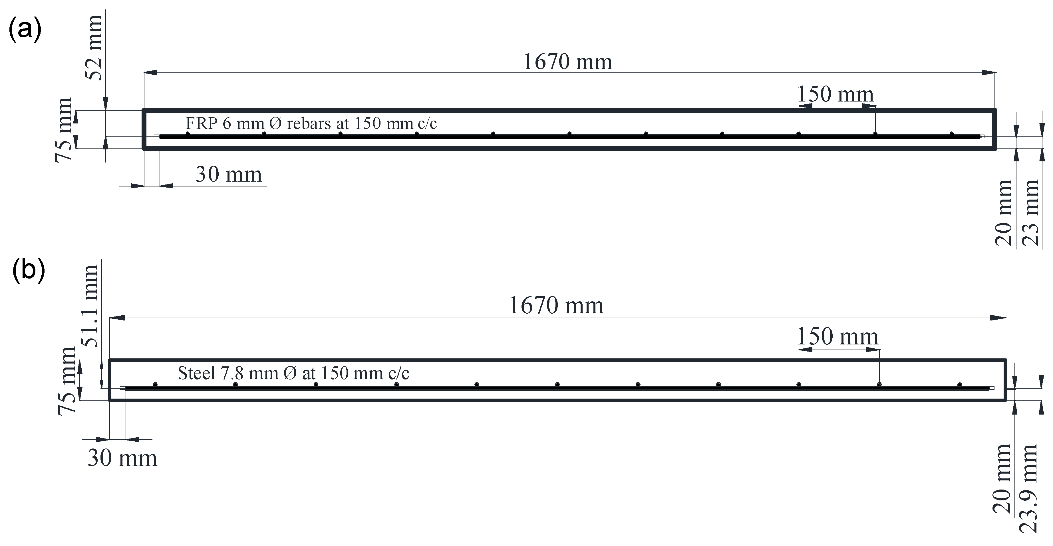
Based on the manufacturer’s product data sheet, the physical and mechanical properties of the CFRP and BFRP bars used in this study are listed in Table 1. The surface of the FRP bars and steel reinforcing bars both were deformed (Figure 1a). Locally available ready-mix concrete (Geelong, Australia) was used to cast the concrete slabs. All slabs were cast with the concrete with the same mix design but from two batches of concrete. The ultimate compressive strength of the concrete used in the study is given in Table 2.

2.2. Specimens

Figure 1 and Figure 2 shows the reinforcement details and geometric properties of the fabricated concrete slabs. The length, width, and thickness of the concrete slabs were 1670, 1670, and 75 mm, respectively. Table 2 shows the reinforcement type, cross-sectional area, reinforcement ratio, and concrete compressive strength of each slab specimen. Single-layer reinforcement was provided at the bottom (tension zone) for all concrete slabs, as the slabs were designed to be simply supported from all sides. No reinforcement was placed in the compression zone. The rebar in all seven slabs was spaced at 150 mm centre to centre (c/c) in both directions. Slabs were cast outdoors and covered with plastic sheets for 3 days to prevent moisture loss and ensure adequate curing, followed by air curing for 28 days. Figure 3a shows the casting of concrete slabs, and Figure 3b illustrates the FRP mesh used in the concrete slab.

2.3. Test Setup and Procedure

A monotonic uniformly distributed load (UDL) was imposed on all concrete slabs using a load frame with a capacity of 500 kN. The UDL fixture attached to the load frame is depicted in Figure 4a. The fixture was composed of 16 loading pistons; the diameter of each piston was 175 mm, all acting as loading points to equally distribute the load. A schematic diagram of the loading arrangement is shown in Figure 4b. The slabs were simply supported at the end, resting on a steel frame with a span of 1600 mm between supports. Preloading up to 10 kN was applied at a loading rate of 0.04 kN/s for a few times to allow for the supports’ settlements and relieve any residual stresses. After pre-loading, the slabs were initially loaded at a loading rate of 0.08 kN/s up to 35 kN and subsequently loaded up to failure at a rate of 0.6 mm/min. The concrete slabs were carefully investigated after each loading step. To record the structural responses under the applied loads, the slabs were instrumented with one LVDT (placed at the mid-span of the slab), two electrical strain gauges at the top, and two additional electrical strain gauges at the bottom of the slabs.

3. Test Results and Discussion

This section presents the observed failure modes, load–deflection relationship, flexural stiffness, flexural moment capacity, ultimate bending moment, strain distribution in FRP rebars, and the punching shear capacity of the concrete slabs.

3.1. The Failure Modes

The FRP-RC slabs experienced higher cracks compared to the steel-RC slab during loading. The cracking patterns formed in the concrete slabs are shown in Figure 5. Since the span lengths of all slabs in both directions were equal, they were subjected to an equal amount of bending moment in both directions. Consequently, all slabs developed cracks in both directions almost equally, as shown in Figure 5a–c. The steel-RC slab failed due to the bending moment, as no catastrophic type of failure was observed. Since the steel-RC slab was designed as an under-reinforced member, steel rebars reached yield strain before concrete reached failure strain. FRP reinforced concrete structures are designed to be over-reinforced, as suggested in Canadian (CAN/CSA) and American (ACI) standards. Hence, for FRP-RC slabs, concrete reached its ultimate strength, resulted in punching shear failure. The formation of intermediate cracks in FRP-RC slabs during loading resulted in a progressive drop in shear capacity, which eventually led to shear failure without the rupture of the FRP rebars.

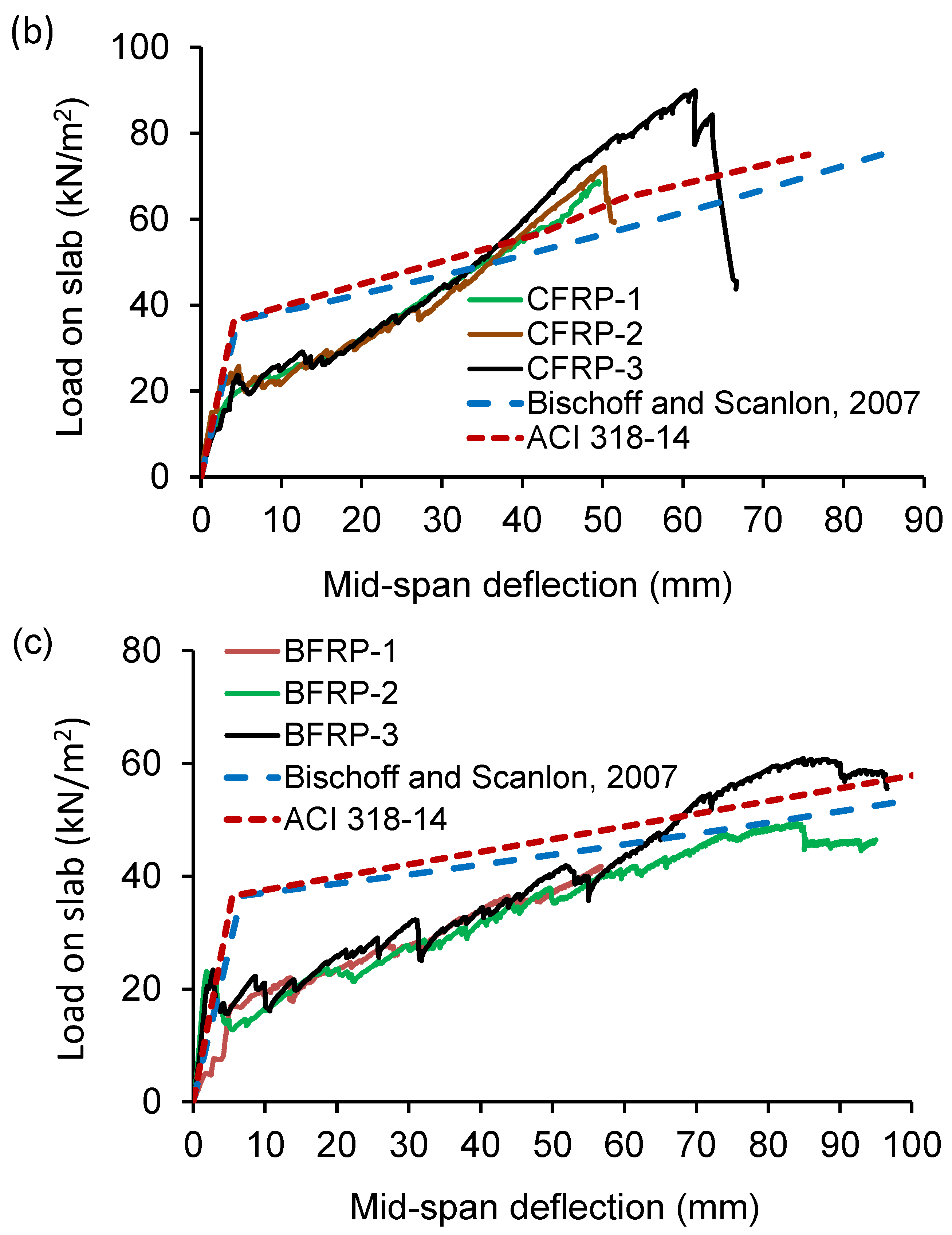
3.2. The Load–Deflection Behaviour

Figure 6 shows the load versus mid-span deflection curves of all the concrete slabs. The uncracked state of the curves, where load–deflection responses are linear, reflect that all concrete slabs performed similarly before cracking. Once applied loads exceeded the rupture strength of the concrete, cracks were developed in the concrete slabs. As loading progressed, slabs developed more cracks and failed when the load reached the peak value. During the loading, whenever a major crack was developed in the concrete slab, RC slabs showed a small drop in load in the load–deflection curve. Compared to the steel-RC slab, both the CFRP- and BFRP-RC slabs exhibited higher deflection but lower ultimate load capacity at failure. It was noted that compared to the CFRP reinforced slabs, the BFRP-RC slabs experienced higher deflection but withstood the lowest ultimate load.

3.3. Stiffness of the Slabs

According to ACI 440.1R-15 [1], the performance of FRP-RC structures is controlled by serviceability criteria. Additionally, ACI 440.1R-15 [1] demonstrated that FRP-RC structures show relatively lower stiffness after cracking when compared against steel-RC structures having the same reinforcement ratio. The present study illustrated the stiffness of the uncracked slabs (within the cracking load) and the stiffness of the cracked sections beyond the serviceable limit. The stiffnesses of all slabs were determined from the slopes of the load–deflection curves [4]. To determine the stiffness of the uncracked and cracked sections of the slabs, three tangents (I, II, III) were drawn on load–deflection curves, as shown in Figure 7. Tangent-I and tangent-II present the linear elastic and plastic behaviours of the slabs under superimposed loads, respectively. The slope of tangent-I and tangent-II presents the stiffness of the uncracked and cracked sections of the slabs, respectively. Tangent-III presents the curves after the fracture point.
Before cracking, most FRP-RC slabs (CFRP-2, CFRP-3, BFRP-2, and BFRP-3) showed similar stiffnesses to the steel-RC slab. After cracking, however, the flexural stiffness of the FRP-RC slabs was reduced significantly, which triggered higher deflections of the slabs under the subsequent loadings. Table 3 list the stiffness values of cracked and uncracked sections of the slabs. It can be noted that the reinforcement ratio of the FRP-RC slabs was 40% less than that of the steel-RC slab, and the axial rigidities of CFRP and BFRP rebars were 41% and 16% of that of the steel rebar. However, CFRP- and BFRP-RC showed 64% and 48% of the cracked stiffness of the steel-RC slab. Within the elastic limit, the stiffness of BFRP and CFRP-RC members was found to be comparable to the steel-RC members. Beyond the cracking load, the stiffness of FRP-RC members dropped substantially due to the formation of numerous cracks.

3.4. Experimental Loads and Moments of the Concrete Slabs

Table 4 summarises the experimental cracking load and moment, serviceable moment, and ultimate positive bending moments of the RC slabs. The moment calculation methods are described in the subsequent sections. Additionally, this study chose two principles to find out the serviceable bending moment (Ms) of the FRP-RC slabs. The first principle was taken from ISIS-07 [37] that states that Ms is the bending moment corresponding to the FRP bar strain of 2000 µε under applied loads. The second principle to determine Ms was taken from Bischoff’s study [38], where Ms is estimated as 30% of the ultimate bending moment (Mu).

3.4.1. Cracking Moment

The experimental cracking moment (Mcr-exp) was determined from the cracking loads, as described in Equation (1).
M c r e x p = 0.036 w d l + w c r l 2
where M c r e x p = experimental cracking moment in kN-m per meter, w c r = experimental UDL on the slab in kN/m2 that created cracks, and l is the effective span length of the slab in m.
The cracking moment capacity of concrete members depends on the modulus of rupture value of concrete and the cross-sectional properties of the members. According to ACI 318-14 [39], the rupture strength of concrete was determined using Equation (2). On average, the moduli of rupture of concrete of the steel, CFRP, and BFRP-RC slabs were 3.37, 3.55, and 3.55 MPa, respectively.
f r = 0.62 f c
Based on the results, the CFRP- and BFRP-RC slabs showed approximately 6.5 and 3.5% higher cracking moment capacities than the steel-RC slab, respectively. As the cross-sectional properties of all slabs were the same, the variation in the rupture strength of concrete contributed to the higher cracking moment capacities of the CFRP- and BFRP-RC slabs, since the concrete strength was slightly lower in the steel-RC slab (Table 2).

3.4.2. Serviceable State

The flexural bending moment of the FRP-RC member within the service state is the key indicator to assess the performance of the member subjected to out of plane loading [36]. Since FRP bars do not have a risk of corrosion, a larger width of cracks (usually 1.66 times wider than that in typical RC members) are tolerated in FRP-RC member design [40]. Thus, to limit the crack widths in FRP- and steel-RC members subjected to flexure, an upper limit on FRP and steel rebars’ strain equal to 2000 µε and 1200 µε are allowed within the serviceable state, respectively [37,40].
According to ISIS-07 [37], the service load capacities of the CFRP- and BFRP-RC slabs are approximately 58.00 and 43.00 kN/m2, respectively. Additionally, based on Bischoff’s study [38], the CFRP- and BFRP-RC slabs offer service load capacities of 52.00 and 34.00 kN/m2, respectively. The service live load capacities of the CFRP- and BFRP-RC slabs computed from the ISIS-07 [37] method are 1.13 and 1.28 times higher than that of the CFRP- and BFRP-RC slabs estimated following Bischoff’s study [38]. These serviceable live load capacities demonstrate the suitability of using CFRP and BFRR rebar in concrete slab.

3.4.3. Ultimate Moment

To determine the ultimate positive bending moment capacity of a simply supported two-way concrete slab, the coefficient method of ACI 318-14 [39] was followed. The ultimate positive bending moment ( M u ) in kN-m per unit meter was determined following Equation (3).
M u = 0.036 w d l + w l l l 2
where w d l is the self-weight of the slab, and w l l is the experimental ultimate UDL applied on the slab in kN/m2.
Results showed that the CFRP- and BFRP-RC slabs possessed approximately 17 and 45% lower ultimate moment capacities compared to the steel-RC slab, respectively. Furthermore, the ultimate moment capacity of the steel-RC slab was 4.17 times higher than its cracking moment capacity, whereas on average, the ultimate moment capacities of the CFRP- and BFRP-RC slabs was 3.25 and 2.25 times higher than their cracking moment capacities. The reason for that is due to the development of numerous wide cracks in the FRP-RC slabs beyond the cracking load. As the FRP bar has a lower modulus of elasticity compared to steel, the FRP-RC slabs underwent significantly higher deflections under the same load. Consequently, numerous cracks were developed beyond the serviceable limit, and cracking continually increased until the failure. Progressive cracking significantly reduced the flexural capacity of the FRP-RC slabs, as the propagation of cracks into the compressive zone led to the reduction in the effective depth of the slabs. Thus, the FRP-RC slabs showed lower ultimate moment capacity compared to the steel-reinforced slab. Furthermore, the BFRP-RC slabs had around 34% lower ultimate moment capacity than the CFRP-RC slabs, as BFRP bars used in the study had approximately 60% lower modulus of elasticity than that of the CFRP bars.

3.5. Displacement Ductility of the Slabs

The displacement ductility of the FRP and steel-RC slabs was estimated as the ratio of the maximum deflection at ultimate load ( Δ m a x ) and the deflection ( Δ x ) at the intersection of the cracked and uncracked section observed in the load–deflection curve [41], as shown in Figure 8. The displacement ductility values of the slabs are given in Table 5. On average, the CFRP- and BFRP-RC slabs exhibited 1.26- and 2.18-times higher ductility compared to that of the steel-RC slab. Therefore, FRP-RC members even with a lower reinforcement ratio can have higher ductility compared to typical steel reinforcement slabs with a higher reinforcement ratio (reinforcement ratios in the steel and FRP-RC slabs were 0.0062 and 0.0036, respectively). Moreover, the enhanced ductility properties of the BFRP-RC slabs should not be overlooked, as, on average, the BFRP reinforced slabs demonstrated 1.72 times higher ductility than CFRP reinforced slabs. The reason for this is that BFRP-RC slabs experienced a gradual decrease in the load capacity with incremental displacement, whereas CFRP reinforced slabs underwent a sharp decrease in load capacity. This demonstrates that BFRP bars could effectively be used to reinforce structural concrete where higher ductility of the member is desired.

3.6. Residual Deflections and Elastic Recovery of the Slabs

Table 6 shows the ultimate deflection at failure load and the residual deflection after load release. This behaviour is consistent with the findings reported by other researchers [22,42,43]. The residual deflection ( Δ R ) and the ultimate deflection ( Δ U ) ratio ( Δ R / Δ U ) represent the permanent deflection when the applied load was released. Both the CFRP- and BFRP-RC slabs showed a significant elastic recovery when the slabs were unloaded. The elastic recovery of each slab was calculated as the ratio of the difference between ultimate deflection and residual deflection with respect to ultimate deflection. This implies that the FRP bars did not reach their rupture strain under the superimposed loads. However, the elastic recovery in the concrete slab reinforced with steel was not observed. Since the steel-RC slabs are usually designed as under-reinforced members, permanent deformation occurred in the steel of the concrete slab reinforced with steel rebars.

3.7. Experimental vs. Theoretical Deflections

The amount of deflection at the centre of a two-way RC slab is considered identical irrespective of the direction of a slab. It depends on the modulus of elasticity of concrete, applied load intensity, and geometrical properties, such as moment of inertia and span length of the slab. The theoretical centre point deflection of the RC slabs was calculated using Equation (4).
Δ = 5 w l 4 384 E I e
where w = w d l + w l l , l = effective span length, E = modulus of elasticity of concrete, and I e = effective moment of inertia of the section, which is related to tangent (II) of Figure 7.
Figure 9a–c shows comparative studies on the experimental and theoretical load–deflection curves obtained based on the guidelines provided in ACI 318-14 [39], ACI 440.1R-15 [1], and Bischoof and Scanlon (2007) [44]. The experimental ultimate load capacities of the steel-, CFRP-, and BFRP-RC slabs were 90.26, 74.95, and 49.68 kN/m2, respectively. According to ACI 318-14 [39], the theoretical ultimate load capacities of the steel, CFRP, and BFRP-RC slabs are 90.00, 62.50, and 52.70 kN/m2, respectively, corresponding to the same deflection values obtained under the ultimate experimental loads. The steel-RC slab showed the same load capacity experimentally and theoretically. The experimental load capacity of the CFRP-RC slabs was found to be approximately 1.20 times higher than the theoretical ultimate load capacity. However, the BFRP reinforced concrete slabs showed 6% less experimental load capacity than its theoretical counterpart.

3.8. Load–Strain Profile of Rebars Used in the Slabs

Figure 10 shows the strain distributions in the reinforcements of the concrete slabs measured using electrical strain gauges. The dashed lines present strain in the rebar in one direction, while the continuous lines correspond to the strain in the rebar in other (perpendicular) direction (see Figure 1 for directions and the location of strain gauges). The strain value acting in the rebar from one slab of each group is shown in Figure 10. The maximum strain at failure loads in the steel, CFRP, and BFRP rebars were approximately 14,200, 11,000, and 19,000 µε, respectively. The maximum measured strain in CFRP rebars was about 85% of its ultimate strain, while the measured strain in the BFRP rebars exceeded the nominal elongation by 2.9%. Although the BFRP rebars showed higher elongation at ultimate load than other rebars types used, the BFRP rebars were not ruptured, as they showed elastic recovery during unloading. Table 7 lists the measured strain values and developed stresses in FRP rebars at failure loads. Additionally, the ultimate strain of concrete for each slab computed using ACI 440.1R-15 [1] is presented. The developed stress in all FRP rebars at ultimate load remained well below the rupture strength. This implies that FRP rebars did not rupture when the slabs failed due to loads. As punching shear of concrete triggers the failure of FRP-RC slabs, this study recommends high strength concrete to be used in concrete structures reinforced with FRP rebars to achieve high resistance against punching shear force.

3.9. Flexural Moment Capacities of the Concrete Slabs

Table 8 shows the resisting moment capacity ( M n ) of the concrete slabs calculated following ACI 318-14 [39] and ACI 440.1R-15 [1], and the ultimate positive bending moment at failure load. Additionally, the reinforcement ratio used in the study and the balanced reinforcement ratio for the slabs are listed. Since the resisting moment capacities of FRP-RC slabs are higher than the ultimate positive bending moment at failure, all FRP-RC slabs were safe against flexural failure. However, the steel-RC slab failed due to bending, as the resisting moment capacity of the steel-RC slab was less than the ultimate bending moment. The failure of the steel-RC slab occurred due to the yielding of steel rebars because it was designed as an under-reinforced member.

3.10. Punching Shear Capacity of the Slabs

Two critical sections were considered to investigate the punching shear capacity of the RC slabs. Section 1 was around the individual loading piston, and Section 2 was around the total loading considering a point load, as presented in Figure 11a,b, respectively. To determine the theoretical punching shear capacity of the FRP-RC slabs, the punching shear prediction models proposed by ACI 440.1R-15 [1], El-Gamal et al. [35], and Metwally [6] were chosen. All slabs were found to be adequately safe against punching shear along the critical Section 1. The punching shear capacity along the critical Section 2 obtained from the analytical prediction models was comparable with the experimental loads, as listed in Table 9. The ratio V p r e d / V e x p for each theoretical model was calculated for each type of reinforcement. Based on the ACI 318-14 [39] model, the punching shear capacity V p r e d of the steel-RC slab was 240.10 kN, while the ultimate experimental failure load V e x p was 222.50 kN. This infers that the steel-RC slab was safe against punching shear force as V p r e d / V e x p = 1.08 for the slab.
According to ACI 440.1R-15 [1], the CFRP-3, BFRP-2, and BFRP-3 slabs were not safe against punching shear as V p r e d / V e x p was less than 1.00. Although the CFRP-1, CFRP-2, and BFRP-1 slabs showed V p r e d / V e x p ratios slightly higher than 1.00, they were vulnerable to punching shear or were likely to fail due to punching shear.
In contrast, based on the punching shear prediction model proposed by El-Gamal et al., [35], all FRP-RC slabs except CFRP-3 and BFRP-3 were found to be safe against the punching shear. Furthermore, all FRP-RC slabs were found resilient against the punching shear when the prediction model proposed by Metwally [6] was considered. Compared to El-Gamal et al. [35] and Metwally [6], ACI 440.1R-15 [1] underestimates the two-way shear capacity of the FRP-RC slab.
In summary, the punching shear capacity of an RC slab highly depends on the effective depth and compressive strength of concrete. If the effective depth of a slab is compromised due to the formation of cracks, the punching shear capacity is significantly reduced. As the FRP-RC slabs experienced increasingly higher cracking than the steel-RC slab while loading, the effective depths of the slabs were significantly reduced. Consequently, the FRP-RC slabs failed due to punching shear, while the steel-reinforced slab failed due to flexural bending moment.

3.11. Experimental Load and Internal Capacities of the Slabs

According to ACI 440.1R-15 [1] and ACI 318-14 [39], based on the internal resisting moments, punching shear capacities and one-way shear capacities, the load capacities of the RC slabs per square meter are summarised in Table 10. It is evident that the steel-RC slab was safe against shear forces but failed due to flexural bending moment. Nevertheless, all FRP-RC slabs were safe against bending moment and one-way shear but were critical against punching shear. Thus, this study recommends high strength concrete and/or additional shear reinforcement for FRP-RC slabs to mitigate the punching susceptibility of the slabs.

4. Summary and Conclusions

This study demonstrates structural performance of two-way concrete slabs reinforced with CFRP, BFRP, and conventional steel rebars. The load versus mid-span deflection behaviour, cracked and uncracked stiffness, serviceability, flexural moment capacity, and punching and one-way shear capacity of the RC slabs were investigated and considered as indicators of structural performance. Based on the experimental and analytical investigation, the following essential conclusion can be drawn:
  • Compared to the typical steel-RC slab, both the CFRP- and BFRP-RC slabs experienced significantly higher deflection and cracking while loading. However, the performance of the FRP-RC slabs was comparable to that of the steel-RC slab within the serviceability limit.
  • Although the axial rigidity of CFRP and BFRP rebars are 41% and 16% of that of steel rebar, the CFRP- and BFRP-RC slabs exhibited 64% and 48% the stiffness of the steel-RC slab after cracking.
  • Both the CFRP- and BFRP-RC slabs showed significant elastic recovery during unloading, which was not the case in the steel-RC slab. This indicates that the FRP rebars did not reach their rupture strain, as CFRP and BFRP rebars reached 71% and 78% of their rupture strength at failure, respectively.
  • Beyond the peak load, the BFRP-RC slabs experienced a gradual decrease in the load capacity with incremental displacement, whereas the CFRP-RC slabs underwent a sharp decrease in load capacity, similar to the steel-RC slab. Consequently, the CFRP- and BFRP-RC slabs exhibited 1.26- and 2.18-times higher displacement-ductility than that of the steel-RC slab. The BFRP-RC slabs demonstrated 1.72-times higher ductility than CFRP-RC slabs because the percentage of elongation of BFRP rebars was higher than that of CFRP rebars.
  • The steel-RC slab failed due to flexural tension, and the FRP-RC slabs failed due to punching shear. As the FRP-RC slabs experienced significantly higher cracks, the shear capacity of the slabs dropped gradually with the increase of loading. These cracks resulted in reducing the effective depth of the section. Thus, the FRP-RC slabs failed due to punching shear without any rupture of the FRP rebars.
  • Since the design of the FRP-RC flexural member is governed by serviceability criteria, and the performance of CFRP- and BFRP-RC slabs is comparable with that of the steel-RC slab, CFRP- and BFRP both are suitable to reinforce concrete slabs.
Although FRP rebars are more expensive than steel rebars, they can be an alternative to typical steel rebars to reinforce concrete slabs where corrosion resistance is a concern. Therefore, the benefit of using FRP rebars in concrete is to improve durability. This study demonstrated that CFRP and BFRP rebars both can be an alternative to steel rebars as their performance within the serviceability limit is satisfactory and comparable to steel rebars. Additionally, BFRP is cheaper than CFRP rebar and has a competitive price. Hence, BFRP bars can be a choice to reinforce structural concrete where durability and/or higher strength-to-weight ratio is desired. However, additional shear reinforcement and/or higher strength concrete is recommended to improve the punching shear capacity of the BFRP-RC slabs.

Author Contributions

Conceptualization, M.S. and E.O.G.; methodology, M.S. and E.O.G.; software, M.S. and S.K.S.; validation, S.K.S., M.S. and E.O.G.; formal analysis, S.K.S.; investigation, S.K.S. and M.S.; resources, M.S., E.O.G. and R.A.-A.; data curation, E.O.G.; writing—original draft preparation, S.K.S.; writing—review and editing, M.S. and R.A.-A.; visualization, S.K.S.; supervision, M.S.; project administration, E.O.G.; funding acquisition, M.S., E.O.G. and R.A.-A. All authors have read and agreed to the published version of the manuscript.

Funding

This project was funded by internal research grant of School of Engineering at Deakin University.

Institutional Review Board Statement

Not applicable.

Informed Consent Statement

Not applicable.

Conflicts of Interest

The authors declare no conflict of interest.

References

  1. ACI PRC-440.1-15; Guide for the Design and Construction of Structural Concrete Reinforced with Fiber-Reinforced Polymer Bars. American Concrete Institute: Farmington Hills, MI, USA, 2015.
  2. Wang, X.; Zhang, X.; Ding, L.; Tang, J.; Wu, Z. Punching shear behavior of two-way coral-reef-sand concrete slab reinforced with BFRP composites. Constr. Build. Mater. 2020, 231, 117113. [Google Scholar] [CrossRef]
  3. Shill, S.K.; Al-Deen, S.; Ashraf, M.; Hossain, M.M. Residual properties of conventional concrete repetitively exposed to high thermal shocks and hydrocarbon fluids. Constr. Build. Mater. 2020, 252, 119072. [Google Scholar] [CrossRef]
  4. Mirza, O.; Shill, S.K.; Johnston, J. Performance of Precast Prestressed Steel-Concrete Composite Panels Under Static Loadings to Replace the Timber Transoms for Railway Bridge. Structures 2019, 19, 30–40. [Google Scholar] [CrossRef]
  5. Shill, S.K.; Al-Deen, S.; Ashraf, M.; Elahi, M.A.; Subhani, M.; Hutchison, W. A comparative study on the performance of cementitious composites resilient to airfield conditions. Constr. Build. Mater. 2021, 282, 122709. [Google Scholar] [CrossRef]
  6. Metwally, I.M. Prediction of punching shear capacities of two-way concrete slabs reinforced with FRP bars. HBRC J. 2013, 9, 125–133. [Google Scholar] [CrossRef] [Green Version]
  7. Aljazaeri, Z.; Alghazali, H.H.; Myers, J.J. Effectiveness of Using Carbon Fiber Grid Systems in Reinforced Two-Way Concrete Slab System. ACI Struct. J. 2020, 117, 81–89. [Google Scholar] [CrossRef]
  8. El-Gamal, S.; El-Salakawy, E.; Benmokrane, B. Behavior of Concrete Bridge Deck Slabs Reinforced with Fiber-Reinforced Polymer Bars Under Concentrated Loads. ACI Struct. J. 2005, 102, 727. [Google Scholar] [CrossRef]
  9. Yost, J.R.; Goodspeed, C.H.; Schmeckpeper, E.R. Flexural Performance of Concrete Beams Reinforced with FRP Grids. J. Compos. Constr. 2001, 5, 18–25. [Google Scholar] [CrossRef]
  10. Mahroug, M.; Ashour, A.; Lam, D. Tests of continuous concrete slabs reinforced with carbon fibre reinforced polymer bars. Compos. Part B Eng. 2014, 66, 348–357. [Google Scholar] [CrossRef]
  11. Banthia, N.; Al-Asaly, M.; Ma, S. Behavior of Concrete Slabs Reinforced with Fiber-Reinforced Plastic Grid. J. Mater. Civ. Eng. 1995, 7, 252–257. [Google Scholar] [CrossRef]
  12. Cai, J.; Pan, J.; Zhou, X. Flexural behavior of basalt FRP reinforced ECC and concrete beams. Constr. Build. Mater. 2017, 142, 423–430. [Google Scholar] [CrossRef]
  13. Fang, H.; Xu, X.; Liu, W.; Qi, Y.; Bai, Y.; Zhang, B.; Hui, D. Flexural behavior of composite concrete slabs reinforced by FRP grid facesheets. Compos. Part B Eng. 2016, 92, 46–62. [Google Scholar] [CrossRef]
  14. Zhang, B.; Masmoudi, R.; Benmokrane, B. Behaviour of one-way concrete slabs reinforced with CFRP grid reinforcements. Constr. Build. Mater. 2004, 18, 625–635. [Google Scholar] [CrossRef]
  15. Rahman, A.H.; Kingsley, C.Y.; Kobayashi, K. Service and Ultimate Load Behavior of Bridge Deck Reinforced with Carbon FRP Grid. J. Compos. Constr. 2000, 4, 16–23. [Google Scholar] [CrossRef]
  16. Michaluk, C.R.; Rizkalla, S.H.; Tadros, G.; Benmokrane, B. Flexural behavior of one-way concrete slabs reinforced by fiber reinforced plastic reinforcements. ACI Struct. J. 1998, 95, 353–365. [Google Scholar]
  17. Erfan, A.M.; Elnaby, R.M.A.; Badr, A.A.; El-Sayed, T.A. Flexural behavior of HSC one way slabs reinforced with basalt FRP bars. Case Stud. Constr. Mater. 2021, 14, e00513. [Google Scholar] [CrossRef]
  18. Mahroug, M.E.M. Behaviour of Continuous Concrete Slabs Reinforced with FRP Bars. Experimental and Computational Investigations on the Use of Basalt and Carbon Fibre Reinforced Polymer Bars in Continuous Concrete Slabs. Ph.D. Thesis, University of Bradford, Bradford, UK, 2014. [Google Scholar]
  19. El-Salakawy, E.; Benmokrane, B. Serviceability of concrete bridge deck slabs reinforced with FRP composite bars. ACI Struct. J. 2004, 101, 727–736. [Google Scholar]
  20. Taerwe, L. Non-Metallic (FRP) Reinforcement for Concrete Structures: Proceedings of the Second International RILEM Symposium; CRC Press: Boca Raton, FL, USA, 2014. [Google Scholar]
  21. Zhang, Q. Behaviour of Two-Way Slabs Reinforced with Cfrp Bars. Ph.D. Thesis, Memorial University of Newfoundland, St. John’s, NL, Canada, 2006. [Google Scholar]
  22. Rashid, M.I. Concrete Slabs Reinforced with GFRP Bars; Memorial University of Newfoundland: St. John’s, NL, Canada, 2004. [Google Scholar]
  23. Karayannis, C.G.; Kosmidou, P.-M.K.; Chalioris, C.E. Reinforced Concrete Beams with Carbon-Fiber-Reinforced Polymer Bars—Experimental Study. Fibers 2018, 6, 99. [Google Scholar] [CrossRef] [Green Version]
  24. Bilotta, A.; Compagnone, A.; Esposito, L.; Nigro, E. Structural behaviour of FRP reinforced concrete slabs in fire. Eng. Struct. 2020, 221, 111058. [Google Scholar] [CrossRef]
  25. Amran, Y.H.M.; Alyousef, R.; Rashid, R.S.M.; Alabduljabbar, H.; Hung, C.-C. Properties and applications of FRP in strengthening RC structures: A review. Structures 2018, 16, 208–238. [Google Scholar] [CrossRef]
  26. Huang, Z.; Zhao, Y.; Zhang, J.; Wu, Y. Punching shear behaviour of concrete slabs reinforced with CFRP grids. Structures 2020, 26, 617–625. [Google Scholar] [CrossRef]
  27. Yu, X.; Zhou, B.; Hu, F.; Zhang, Y.; Xu, X.; Fan, C.; Zhang, W.; Jiang, H.; Liu, P. Experimental investigation of basalt fiber-reinforced polymer (BFRP) bar reinforced concrete slabs under contact explosions. Int. J. Impact Eng. 2020, 144, 103632. [Google Scholar] [CrossRef]
  28. Hassan, M.; Benmokrane, B.; ElSafty, A.; Fam, A. Bond durability of basalt-fiber-reinforced-polymer (BFRP) bars embedded in concrete in aggressive environments. Compos. Part B Eng. 2016, 106, 262–272. [Google Scholar] [CrossRef]
  29. Adhikari, S. Mechanical Properties and Flexural Applications of Basalt Fiber Reinforced Polymer (BFRP) Bars. Ph.D. Thesis, University of Akron, Akron, OH, USA, 2009. [Google Scholar]
  30. Sun, X.; Gao, C.; Wang, H. Bond performance between BFRP bars and 3D printed concrete. Constr. Build. Mater. 2021, 269, 121325. [Google Scholar] [CrossRef]
  31. Balea, L.; Dusserre, G.; Bernhart, G. Mechanical behaviour of plain-knit reinforced injected composites: Effect of inlay yarns and fibre type. Compos. Part B Eng. 2014, 56, 20–29. [Google Scholar] [CrossRef] [Green Version]
  32. Deák, T.; Czigány, T. Chemical composition and mechanical properties of basalt and glass fibers: A comparison. Text. Res. J. 2009, 79, 645–651. [Google Scholar] [CrossRef]
  33. Attia, K.; Alnahhal, W.; Elrefai, A.; Rihan, Y. Flexural behavior of basalt fiber-reinforced concrete slab strips reinforced with BFRP and GFRP bars. Compos. Struct. 2019, 211, 1–12. [Google Scholar] [CrossRef]
  34. Nanni, A. Flexural Behavior and Design of RC Members Using FRP Reinforcement. J. Struct. Eng. 1993, 119, 3344–3359. [Google Scholar] [CrossRef]
  35. El-Gamal, S.; El-Salakawy, E.; Benmokrane, B. A new punching shear equation for two-way concrete slabs reinforced with FRP bars. ACI Spec. Publ. 2005, 230, 877–894. [Google Scholar]
  36. Goonewardena, J.; Ghabraie, K.; Subhani, M. Flexural Performance of FRP-Reinforced Geopolymer Concrete Beam. J. Compos. Sci. 2020, 4, 187. [Google Scholar] [CrossRef]
  37. Provis, J.L.; Rose, V.; Bernal, S.A.; van Deventer, J.S.J. High-Resolution Nanoprobe X-ray Fluorescence Characterization of Heterogeneous Calcium and Heavy Metal Distributions in Alkali-Activated Fly Ash. Langmuir 2009, 25, 11897–11904. [Google Scholar] [CrossRef] [PubMed]
  38. Bischoff, P.; Gross, S.; Ospina, C. The story behind proposed changes to ACI 440 deflection requirements for FRP-reinforced concrete. Spec. Publ. 2009, 264, 53–76. [Google Scholar]
  39. ACI CODE-318-14: Building Code Requirements for Structural Concrete and Commentary; American Concrete Institute: Farmington Hills, MI, USA, 2014.
  40. Bischoff, P.H. Reevaluation of Deflection Prediction for Concrete Beams Reinforced with Steel and Fiber Reinforced Polymer Bars. J. Struct. Eng. 2005, 131, 752–767. [Google Scholar] [CrossRef]
  41. Rakhshanimehr, M.; Esfahani, M.R.; Kianoush, M.R.; Mohammadzadeh, B.A.; Mousavi, S.R. Flexural ductility of reinforced concrete beams with lap-spliced bars. Can. J. Civ. Eng. 2014, 41, 594–604. [Google Scholar] [CrossRef]
  42. Benmokrane, B.; Chaallal, O.; Masmoudi, R. Glass fibre reinforced plastic (GFRP) rebars for concrete structures. Constr. Build. Mater. 1995, 9, 353–364. [Google Scholar] [CrossRef]
  43. Ospina, C.E.; Alexander, S.D.B.; Cheng, J.J.R. Punching of Two-Way Concrete Slabs with Fiber-Reinforced Polymer Reinforcing Bars or Grids. Struct. J. 2003, 100, 589–598. [Google Scholar]
  44. Bischoff, P.H.; Scanlon, A. Effective Moment of Inertia for Calculating Deflections of Concrete Members Containing Steel Reinforcement and Fiber-Reinforced Polymer Reinforcement. ACI Struct. J. 2007, 104, 68. [Google Scholar] [CrossRef]
Figure 1. Reinforcement detailing, and the dimensions of the concrete slab. (a) deformed BFRP rebar; (b) reinforcement details.
Jcs 06 00074 g001aJcs 06 00074 g001b
Figure 2. Cross-section (A–A) of (a) FRP reinforced slab and (b) steel reinforced slab.
Jcs 06 00074 g002
Figure 3. Photos of (a) a concrete slab after casting and (b) the single-layer reinforcement of a slab.
Jcs 06 00074 g003
Figure 4. (a) Photo of the UDL application on the concrete slab; (b) schematic diagram of the loading points on a slab.
Jcs 06 00074 g004
Figure 5. Failures of concrete slabs reinforced with (a) CFRP, (b) BFRP, (c) steel rebars, and (d) punching shear failure.
Jcs 06 00074 g005
Figure 6. Load vs. mid-span deflection curves for all concrete slabs.
Jcs 06 00074 g006
Figure 7. Stiffness of all slabs investigated.
Jcs 06 00074 g007
Figure 8. Method of determining displacement ductility of the slabs tested.
Jcs 06 00074 g008
Figure 9. Theoretical and experimental load–deflection curves of (a) steel, (b) CFRP, and (c) BFRP-RC slabs.
Jcs 06 00074 g009aJcs 06 00074 g009b
Figure 10. Strain distribution in the reinforcements of the slabs tested.
Jcs 06 00074 g010
Figure 11. Critical sections to calculate the punching shear force capacity of the slabs. (a) Critical Section 1 around individual loading piston; (b) Critical Section 2 around total loading piston.
Jcs 06 00074 g011
Table 1. Properties of the reinforcing bars (taken from manufacturing data sheet).
ParametersRebar Type
SteelCFRPBFRP
Bar diameter (mm)7.866
Nominal cross-sectional area (mm2)482828
Tensile strength (MPa)50021501300
Elastic modulus (GPa)20014055
Elongation (%)2.27 a1.3 b1.8 b
a Elongation at yielding; b elongation at bar rupture.
Table 2. Compressive strength of concrete and details of reinforcement.
Slab
Specimen
Concrete Compressive Strength, f’c
(MPa)
Reinforcement Area
(mm2/m)
Effective Depth
(mm)
Reinforcement Ratio ρ f
(%)
Steel29.62318.5651.10.62
CFRP-129.62188.50520.36
CFRP-234.59
CFRP-334.59
BFRP-129.62
BFRP-234.59
BFRP-334.59
Table 3. Stiffness of all test slabs.
Slab IDElastic Modulus of Rebars (GPa)Area of Reinforcement
(mm2/m)
Ratio of the Axial Rigidity
(EfrpAfrp)/(EsAs)
Stiffness of Uncracked Section
(kN/mm)
Uncracked Ratio
(FRP/Steel)
Stiffness of Cracked Section
(kN/mm)
Cracked Ratio
(FRP/Steel)
Steel200318.56115.761.005.451.00
CFRP-1140188.500.41413.530.863.450.63
CFRP-229.571.873.440.63
CFRP-316.161.023.670.67
BFRP-155188.500.1627.280.462.470.45
BFRP-227.121.722.650.49
BFRP-322.311.412.610.48
Table 4. Cracking moment, serviceable moment, and the ultimate bending moment of the concrete slabs studied.
Slab IDCracking Load, Pcr (kN)Cracking Moment, Mcr-exp
(kN-m)/m
Serviceable Moment, Ms
(kN-m)/m
Ultimate Load, Pu (kN)Ultimate Bending Moment, Mu
(kN-m)/m
2000 µε0.3 Mu
Steel 50.001.96-2.45222.508.17
CFRP-146.701.842.001.88169.106.25
CFRP-256.032.182.211.97177.506.55
CFRP-357.952.252.572.29207.707.64
BFRP-142.041.671.601.16103.003.87
BFRP-256.502.191.721.34120.104.48
BFRP-357.602.231.741.61144.305.35
Table 5. Displacement ductility of the slabs investigated.
Slab ID Deflection   ( Δ x )   at   the   Intersection   of   the   Tan gents Deflection at Ultimate LoadDuctility of the Slabs
Δ x   ( mm ) Δ m a x   ( mm ) Δ m a x Δ x
Steel-RC slab3.2046.4514.51
CFRP-12.8549.5817.39
CFRP-22.2050.2622.84
CFRP-34.2563.6314.97
BFRP-14.8056.7911.83
BFRP-22.1585.0039.53
BFRP-32.0087.0043.504
Table 6. The ultimate and residual deflections of the slabs.
Slab IDDeflection at
Serviceability
Limit Δ s   ( mm )
Ultimate Deflection
Δ U
Ultimate Deflection
Ratio
Residual   Deflection Δ R Elastic
Recovery
2000 µε0.3 Mu (FRP/steel) (%)
Steel-RC slab-9.9746.45146.450
CFRP-120.16.6549.581.0718.0064
CFRP-24.54.2350.261.0822.8754
CFRP-33.358.663.631.3738.4240
BFRP-15.24.856.791.2224.6957
BFRP-21.351.285.001.8338.1255
BFRP-319.61.787.001.8736.857
Table 7. Stress and strain values of the FRP rebars in the slabs at failure load.
Slab IDUltimate Strain of ConcreteStrain in Rebars at FailureDeveloped Stress in FRP RebarsUltimate Strength of FRP RebarsRatio of Stress/Strength of FRP RebarsRemarks on FRP Rebars
(MPa)(MPa)
Steel0.001990.01420-- -
CFRP-10.001990.01042145821500.67Not ruptured
CFRP-20.002020.0112515750.73
CFRP-30.002020.0113315860.73
BFRP-10.001990.0175296313000.74Not ruptured
BFRP-20.002020.0188710370.79
BFRP-30.002020.0192010560.81
Table 8. Ultimate resisting moment and bending moment of the slabs.
Slab IDReinforcement
Ratio
Balanced Reinforcement
Ratio
Resisting Moment, MnResisting Load, PnUltimate Bending Moment, Mu M n M u   Ratio Remarks
(kN-m/m)(kN)(kNm/M)
Steel0.006230.022697.61206.958.170.93Failed by steel yielding
CFRP-10.003620.0024110.04274.456.251.61Safe against bending moment
CFRP-20.0024811.06302.786.551.69
CFRP-30.0024811.06302.787.641.45
BFRP-10.003620.002406.77183.613.871.75Safe against bending moment
BFRP-20.002397.41201.394.481.65
BFRP-30.002397.41201.395.351.39
Table 9. Experimental and theoretical punching shear capacity of the CFRP- and BFRP-RC slabs based on different analytical models.
Slabs V e x p   ( kN ) ACI 440.1R-15 [1]El-Gamal et al. [35]Metwally [6]
V p r e d   ( kN ) V p r e d / V e x p V p r e d   ( kN ) V p r e d / V e x p V p r e d   ( kN ) V p r e d / V e x p
CFRP-1169.10177.11.05181.51.07202.41.20
CFRP-2177.49184.91.04196.51.11219.11.23
CFRP-3207.74184.90.89196.50.95219.11.05
BFRP-1102.96115.01.12132.91.29148.21.44
BFRP-2120.05119.91.00143.91.20160.51.34
BFRP-3144.34119.90.83143.91.00160.51.11
Table 10. Experimental failure load and internal capacities of the RC slabs.
Slab IDExperimental Failure Load (Pu) of the Slabs in kN/m2Internal Load Resistance (Pn) of the Slabs in kN/m2 Based on P n m P u P n p s P u P n s P u
Flexural Moment
(Pn-m)
Punching Shear Capacity (Pn-ps)One Way Shear Capacity (Pn-s)
Steel90.2783.9697.41122.300.931.081.35
CFRP-168.60111.3471.85124.451.621.051.81
CFRP-272.01122.8475.01134.501.711.041.87
CFRP-384.26122.8475.01134.501.460.891.60
BFRP-141.7974.4946.66124.451.781.122.98
BFRP-248.7281.7048.64134.501.681.002.76
BFRP-358.5481.7048.64134.501.400.832.30
Publisher’s Note: MDPI stays neutral with regard to jurisdictional claims in published maps and institutional affiliations.

