Article

Mechanical Properties and Energy-Absorption Capability of a 3D-Printed TPMS Sandwich Lattice Model for Meta-Functional Composite Bridge Bearing Applications

Laboratory for Track Engineering and Operations for Future Uncertainties (TOFU Lab), School of Engineering, The University of Birmingham, Edgbaston, Birmingham B15 2TT, UK
*
Author to whom correspondence should be addressed.
J. Compos. Sci. 2022, 6(3), 71; https://doi.org/10.3390/jcs6030071
Submission received: 1 February 2022 / Revised: 8 February 2022 / Accepted: 21 February 2022 / Published: 24 February 2022
(This article belongs to the Special Issue 3D Printing Composites)

Abstract

:
This paper reports on a proposed novel 3D-printed sandwich lattice model using a triply periodic minimal surface (TPMS) structure for meta-functional composite bridge bearings (MFCBBs). It could be implemented in bridge systems, including buildings and railway bridges. A TMPS structure offers a high performance to density ratio under different loading. Compared to typical elastomeric bridge bearings with any reinforcements, the use of 3D-printed TPMS sandwich lattices could potentially lead to a substantial reduction in both manufacturing cost and weight, but also to a significant increase in recyclability with their better mechanical properties (compressive, crushing, energy absorption, vibration, and sound attenuation). This paper shows predictions from a numerical study performed to examine the behaviour of a TPMS sandwich lattice model under two different loading conditions for bridge bearing applications. The validation of the modelling is compared with experimental results to ensure the possibility of designing and fabricating a 3D-printed TPMS sandwich lattice for practical use. In general, the compressive experimental and numerical load–displacement behaviour of the TPMS unit cell are in excellent agreement within the elastic limit region. Moreover, its failure mode for bridge bearing applications has been identified as an elastic–plastic and hysteretic failure behaviour under uniaxial compression and combined compression–shear loading, respectively.

1. Introduction

Bridge bearings play an important role in bridge systems as their main functions are to accommodate/transfer the deformations/forces between the superstructure and the substructure of a bridge whilst supporting the bridge weight. As such, if bearings are used for buildings, the compressive and shear behaviour are considered [1]. However, these bearings can undergo rotational displacements when they are utilised as bridge/railway bearings. [2,3]. It is important to investigate these displacements for bridge bearing applications. Based on a critical review [4,5,6], bridge bearings should provide proper vertical stiffness to withstand the weight of a bridge superstructure and be able to transfer dead and live loads to the substructure. Additionally, these bridge bearings should be flexible in the horizontal direction to be able to facilitate rotational or lateral displacements occurring by girders. The failure of bridge bearings caused by these concerns possibly results in damage to the bridge structure or accelerated bridge deterioration [7].
Typical bridge bearings can be classified as either elastomeric or high load multi-rotational bridge bearings, including spherical, disc, and pot ones [8]. It is important to note that, in this paper, we focus on the development of a 3D-printed TPMS sandwich lattice model for meta-functional composite bridge bearings compared to conventional elastomeric bridge bearings without/with any reinforcements. A key part of an elastomeric bridge bearing is the elastomeric layers which are also known as rubber ones layers [9]. Rubber layers are combined with alternate reinforcement layers (steel plates or fibre sheets), which provide a high modulus in order to increase the stiffness of the bearings in the vertical direction by resisting the bugling of the rubber as shown in Figure 1b. Additionally, elastomeric layers are able to be directly utilised without being reinforced (plain bridge bearings).
Elastomeric bridge bearings (EBBs), which are basically laminated with steel plates (steel-laminated elastomeric bridge bearings, SLEBBs), can alternatively be replaced with fibre sheets (unboned fibre-laminated elastomeric bridge bearings, UFLEBBs) as another reinforced material. The main benefit of using fibre sheets in bridge bearings instead of the other ones is that they are easily installed under the girders. However, UFLEBBs have no rigid end plates leading to a lack of mechanical connections between the superstructure and the substructure of a bridge. This causes these bearings with the fibre reinforcement to experience a particular rollover behaviour under shear and a lift-off behaviour under high rotational displacements due to the lack of flexural rigidity in the fibre reinforcement [10], as presented in Figure 1c,d, respectively.
According to reviews in [11,12,13,14], it has been found that these behaviours can eliminate the circumstance of large tensile stresses in the UFLEBBs when they are subjected to shear or rotational loading. As such, higher tensile stresses can occur in the SLEBBs under lateral and rotational deformations due to their fastening to top and bottom contact supports, which can initially accelerate bearing deterioration. However, both steel/unbonded fibre-laminated elastomeric bridge bearings are still heavy, costly, and non-recyclable due to rigid steel end plates, steel-reinforced plates, and rubber block layers. Furthermore, in order to afford to eliminate the failure patterns of both SLEBBs and UFLEBBs as previously mentioned, the development of a proposed novel bridge bearing model has been considered in this paper.
Nowadays, the use of 3D-printed complex structural components using lattice structures applied in civil engineering is rapidly becoming attractive [15]. Among the various lattice structures presented in Figure 2, the triply periodical minimal surface (TPMS) structures which are among those lattice structures have received considerable attention with potential advantages throughout struct-based lattices (also known as TPMS lattices such as schwarz primitive (SP), gyroid, etc.), because of their low weight to strength ratios and weight to cost ratios, good crashworthiness performance, and high-energy absorption [16,17,18,19,20].
At the same time, additive manufacturing (3D printing) approaches provide the opportunity to realise TPMS parts with complicated designs and features. TPMSs are minimal surfaces which are periodic in three-coordinate directions with zero mean curvatures, free of self-intersections. Moreover, they show superior 3D printing material properties as continuous curves. This means that previous layers support the following layers without support [21,22,23]. Compared to other lattice structures, they need support or are limited by their angle [24].
Another benefit of using TPMS structures is that these structures exhibit a uniform stress distribution, whilst struct-based structures can undergo stress concentrations close to the joints of the structs [24,25,26,27]. In the same way, from our previous work [6,15], local failures of struct-based structures are likely to occur before yielding under compression. Lei Zhang et al. [27] found that TPMS structures exhibited a better stiffness, plateau stress, and energy-absorption ability to struct-based body-centred cubic (BCC) lattices. Additionally, TPMS structures performed better than face-centred-cubic (FCC) lattices [28]. Moreover, other studies have exhibited that the excellent properties of TPMS structures in terms of vibration, acoustic attenuation, and thermal management are better than that of typical lattices [29,30].
Triggered by this point, many studies have recently considered the TPMS geometric design and finite element analysis (FEA), showing that TPMS geometries play an important role in their mechanical response [31,32,33,34,35,36]. TPMS mechanical performances (compressive, crushing, energy absorption, vibration, and sound attenuation, etc.) are not dominated by structure geometry, but also certainly based on material properties [37].
In terms of their performances for bridge bearing applications, they could provide multiple geometry and superior properties, for example, a lightweight structure due to a high vertical/horizontal stiffness to weight ratio and an energy absorber due to its high specific strength and energy absorption per volume, respectively. Nowadays, TMPS structures have been investigated under either compression or impact loading for other civil engineering applications, and extending the use of TMPS sandwich lattices to bridge bearing applications requires the comprehension of their behaviour under compression–shear deformation. Nevertheless, there are currently no studies that have investigated the behaviours of a 3D-printed TPMS structure for bridge bearing applications under compression–shear loading.
In the present study, we present a proposed novel 3D-printed TPMS sandwich lattice model for meta-functional composite bridge bearing applications using a parametric computational and experimental approach. The predictions of the mechanical behaviours of both the load–displacement/stress–strain curves of a TPMS unit cell model and the sandwich lattice model with 3 × 2 × 1 unit cell models, compared to an elastomeric block unit cell model under combined compression–shear loading, could be obtained. In addition, a TPMS structure used in both TPMS models is schwarz primitive (SP) without thickness, because this TPMS structure is likely to own its symmetry in geometry subjected to both two loading conditions. To realise the proposed novel 3D-printed TPMS sandwich model, the validation of the SP unit cell model under uniaxial compression was carried out by comparing the numerical predictions with experimental measurements. Then, the stress–strain relationships of the mechanical behaviours of the proposed novel sandwich lattice model are employed to determine their mechanical properties, for example, elastic modulus (E), shear modulus (G), and Poisson’s ratio (V). These parameters can be adjusted for the further design of novel composite bridge bearings using a sheet-based or double TPMS sandwich lattice subjected to different loading conditions.

2. Methodology Strategy

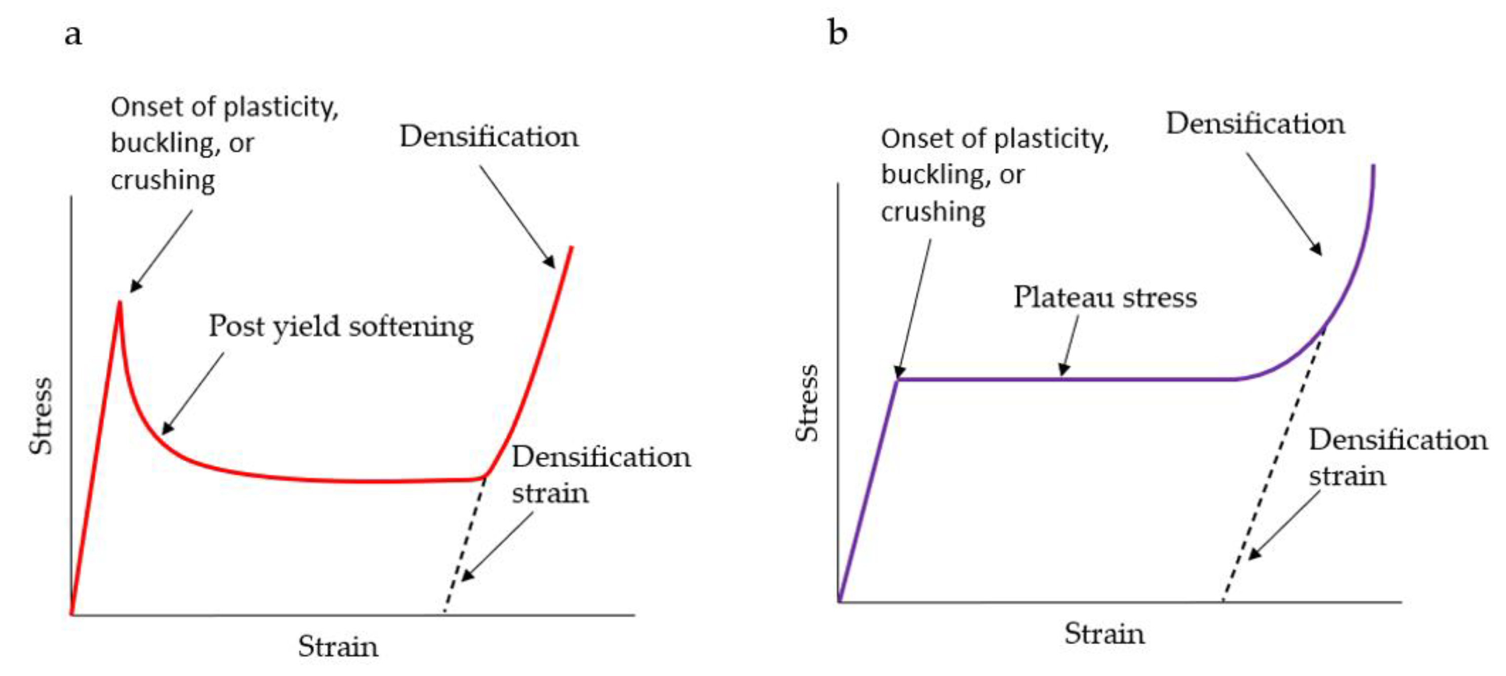
2.1. Gibson–Ashby Model of Cell Structures

In reference [38], Ashby exhibited the correlation between the mechanical properties of the lattice structure and the relative density (modulus of elasticity, plateau stress, and densification strain), which is categorised into two groups of lattice structures with diverse mechanical behaviours. Figure 3a,b demonstrate the typical compressive bending-dominated behaviour and stretch-dominated behaviour of a lattice structure, respectively. It is attributed to these mechanical properties which are based on three factors (lattice geometry, material, and volume fraction). These three factors affect the load–displacement of a lattice structure under any loading. The correlations are referred to the Ashby model:
M l M s = B 1 D l D s k ,
Y l Y s = B 2 D l D s j ,
E d = 1 A D l D s ,
where Ms, Ys, and Ds determine the Young′s modulus, yield strength, and density of a base solid material, respectively, whilst, Ml, Yl, and Dl denote the Young′s modulus, yield strength, and density of a lattice structure, respectively. Ed is the initial densification strain of the lattice structure where the densification point appears. In terms of energy absorption applications, Ed can alternatively be used as the effective limit. Beyond this limit point, the structure will sustain its energy absorption, but the occurrence of transmitted stress is observed over the structure. Additionally, the rest of certain parameters (B1, B2, k, j, and A) is calculated by fitting the result of the compressive experiment in a review [38]. In this paper, the energy absorption capacity of a lattice structure is determined using numerical integration, which provides the region below the stress–strain curve under uniaxial compression. The following equation expresses the energy absorption per unit volume, Sv:
S v = 0 E Y E d E

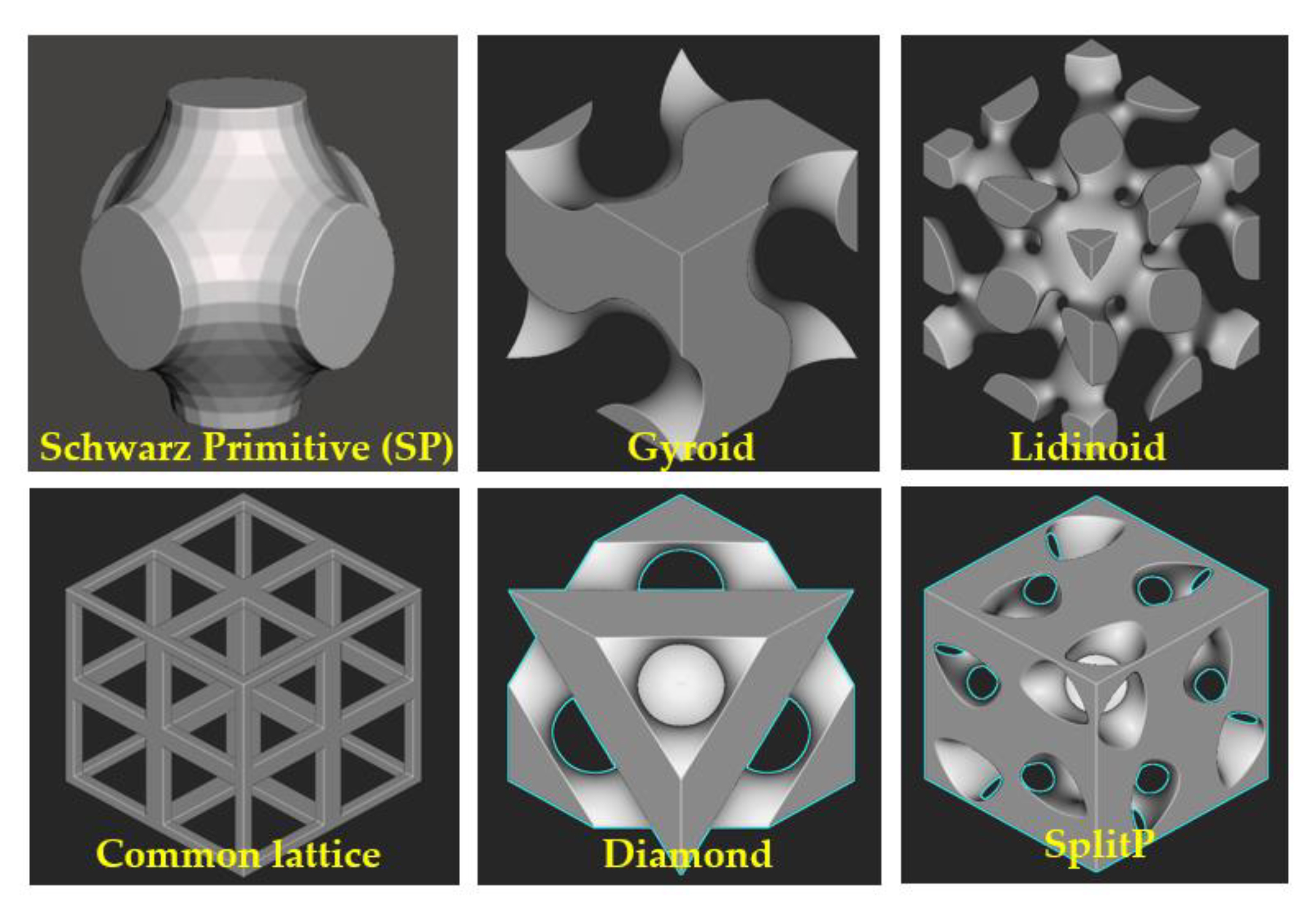
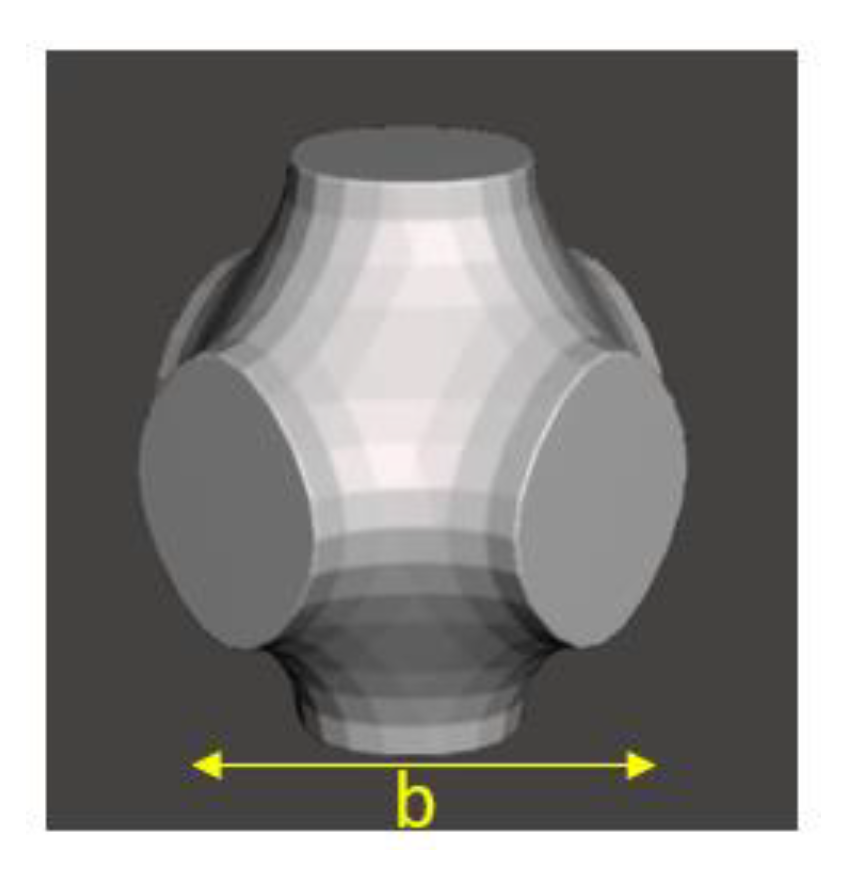
2.2. Schwarz Primitive (SP) Unit Cell Design

The aim of this paper was to exhibit the mechanical behaviour of a proposed novel 3D-printed TPMS sandwich lattice model under uniaxial compression and combined compression–shear loading and to replace a common elastomeric bridge bearing structure with it. Regarding the design of a lattice unit cell model, two key methods can be used to create a solid schwarz primitive (SP). The first method can be used to generate a network struct, known as a skeletal schwarz primitive for a SP unit cell model without thickness. This method is based on one of the subdomains divided by the surface as a solid. Another method is to create a termed sheet-based or double schwarz primitive for a schwarz primitive unit cell model with a thickness, obtained by plotting two minimal surfaces with two variant level sets of the constant k together, leading to an offset from a hypothetical surface at the average of the two level-set surfaces. The TPMS schwarz primitive with a thickness can be approximately generated using the equation of the implicated surface as seen in Equation (5):
c o s 2 π x b + c o s 2 π y b + c o s 2 π z b k = H x , y , z ,
where b denotes the unit cell size of a lattice (Figure 4) and k is the volume fraction of the areas which is divided by the surface [39]. The volume fraction of a lattice describes the relative density of its components. It can also be used to adjust the thickness of the model and to compare models with an identical volume. It is important to note that, in this research, we only use the first method for generating a skeletal SP unit cell model. Figure 4 illustrates the schwarz primitive unit cell CAD model for all simulations in this paper.

2.3. Finite Element Modelling of a Schwarz Primitive and Elastomeric Block Unit Cell

2.3.1. Design, Material, and Geometric Parameters

In this section, the uniaxial compression and combined compression–shear analysis of a 50 mm × 50 mm × 50 mm schwarz primitive unit cell model and an elastomeric block model with the same dimensions for bridge bearing applications are modelled within an elastic–plastic region using the FEA software Abaqus Static 2017 [40]. These two models possess a quasi-isotropic material behaviour with isotropic properties, but only in-plane, which have three certainly independent parameters including the equivalent Young’s modulus (Ex = Ey = Ez), Poisson ratio (Vyx = Vxy = Vyz = Vxz = Vzy = Vzx), and shear modulus (Gxy = Gxz = Gyz). A proposed 3D-printing resin material, also known as photosensitive resin (UV resin), is considered as a model material for all simulations. The designed dimensions of the two models are based on the full-scale dimensions of common bridge bearings used in highway bridge systems in Thailand [41]. This parametric study using a proposed material covers the bridge bearing applications of this paper. Figure 5a,b present the finite element models of a schwarz primitive unit cell and an elastomeric block unit cell in Abaqus, respectively.

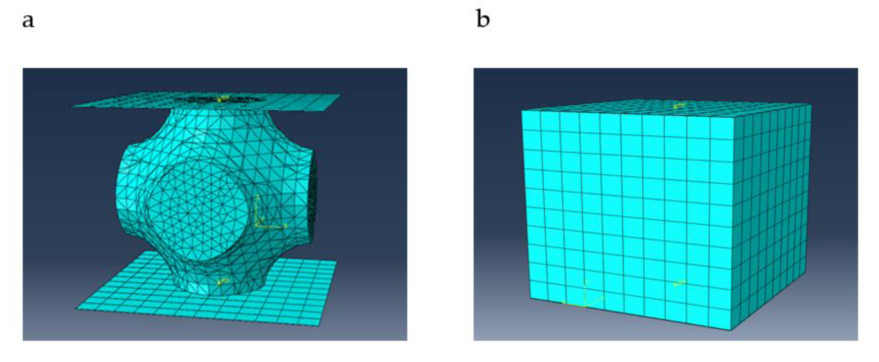
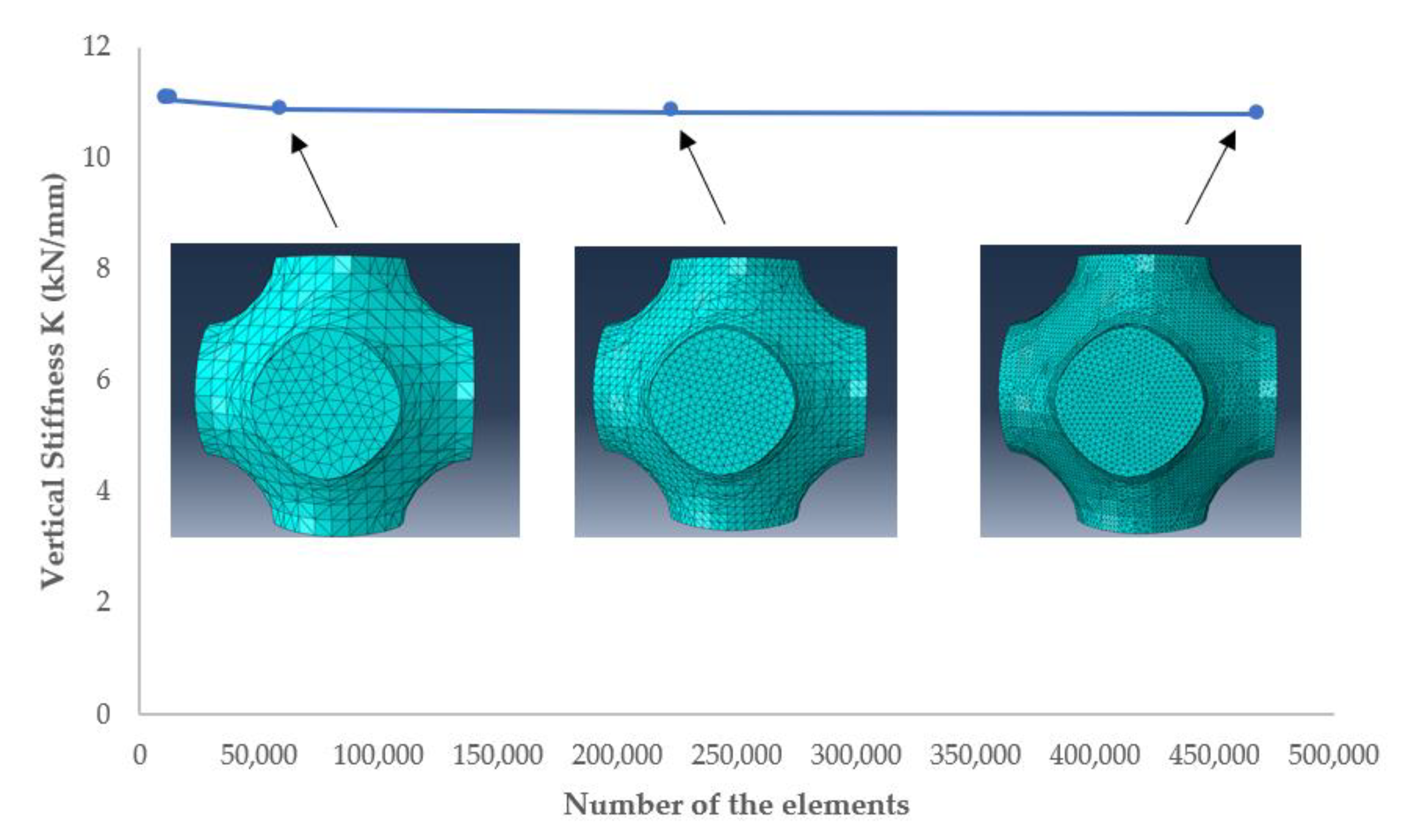
2.3.2. Mesh Generation

The schwarz primitive unit cell model and elastomeric block one are designed and meshed utilising tetrahedral mesh (element type C3D4R) generation from software Abaqus. In order to obtain correct FEA results with high performance from all models in this paper, the mesh sensitivity investigation is considered by observing the vertical stiffness (K) against the whole number of elements. The mesh sensitivity of a schwarz primitive unit cell model is presented as a curve shown in Figure 6. This curve demonstrates that when the mesh size reduces from 5 mm to 0.75 mm, the percentage error of the vertical stiffness is within 3%.

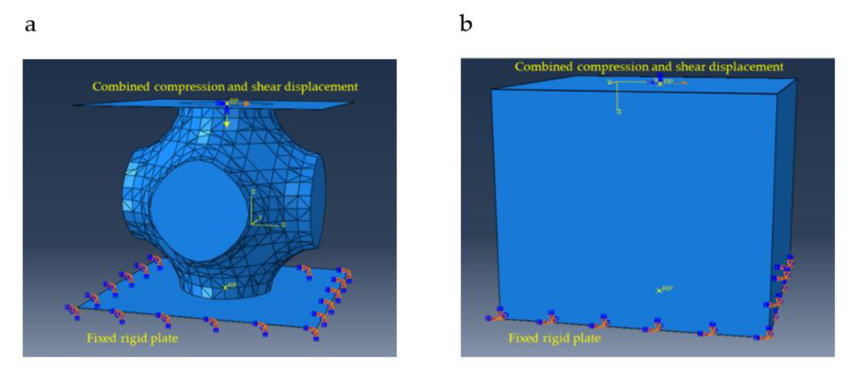
2.3.3. Boundary Conditions and an Applied Force

In this step, the proper selection of boundary conditions is important to observe the behaviour of the schwarz primitive unit cell model and the elastomeric block unit cell model under uniaxial compression and combined compression–shear loading, shown in Figure 7a,b, respectively. For combined compression–shear simulation, each model is located between two thin rigid plates, therefore both the top and bottom faces are tied to those rigid plates. Firstly, a concentrated force is applied to the reference point on the top face of each model. After that, a shear displacement with a periodic sinusoidal amplitude is applied parallel to the same reference point, whilst their bottom surfaces are fixed. Furthermore, the rest of all translational and all rotational degrees of freedom on their reference point and bottom surfaces are fixed to prevent rigid body motion. Additionally, the fronts and sides of the two models are not considered with these boundary conditions. Moreover, the concentrated load and shear displacement for both models are applied by employing the static FEA model on Abaqus. Whilst boundary conditions for uniaxial compression are applied in the same manner, an enforced displacement is applied to the upper reference point moving forwards the bottom of each model instead.

2.3.4. Material Properties

In this research, the proposed photosensitive resin (UV resin) material model is employed for all FEA simulations due to its availability on the 3D printing market and in elastomeric-like material properties. Figure 8 presents the stress–strain curve for a UV resin material used in the simulations of the elastomeric block and schwarz primitive unit cell model. It is important to mention that the stress–strain relationships from the curve are calibrated from experimental data in Abaqus to obtain correct results when simulating.

2.3.5. Data Collection

All finite element simulations for both models are run and their stress–strain curves are obtained. Using a reaction force as an enforced displacement applied to the reference point on the upper rigid plate can give a load and stress can be evaluated by dividing the load with the area of a unit cell. Additionally, strain is obtained from the applied enforced displacement divided by cell height. The force–displacement curves of the uniaxial compression and combined compression–shear behaviours of the SP unit cell and elastomeric block FE model for the simulations are shown in Figure 9 and Figure 10, respectively.

2.4. Mechanical Testing

In order to validate the FEA results of the SP unit cell model, three 50 mm × 50 mm × 50 mm SP unit cell samples were manufactured and tested under uniaxial compression. The SP unit cell model was first designed using the CAD software Solidworks, and then exported as the STL format for the sample preparation of additive manufacturing. Then, three compression samples were manufactured for the same model using a stereolithography (SLA)-based 3D printer. Figure 11 shows one of the final specimens for compression testing. The tests on these three specimens were performed in the build direction to prevent the build orientation effect using a universal testing machine, as shown Figure 11c. During the tests, the load–displacement data were collected by the testing machine and plotted in Excel. Furthermore, photographs are periodically captured to observe the failure behaviour at a displacement of 9.3 mm.

3. Model Validation of the SP Unit Cell Model

Before designing a proposed novel SP lattice model, it is important to first validate the SP unit cell model. Thus, the validation of the SP unit cell model subjected to uniaxial compression is conducted by comparing its numerical predictions with experimental measurements. To mimic the experimental boundary conditions, entire degrees of freedom of the upper and bottom faces are constrained by tying them to rigid plates in the compressive simulation. Figure 12 illustrates representative the force–displacement curves of the compression behaviours of the SP unit cell between the FEA predictions and the experimental results. The results between numerical and experimental data are in excellent agreement within the elastic region. Nevertheless, there is a slight difference in the plastic region. This might be an influence of specimen defects during manufacturing, which leads to a certain time interval for laying the next layer causing the change of properties. It is important to mention that, in this paper, the result of the third experiment is not available because of data errors which might be environmental disturbances during the testing.

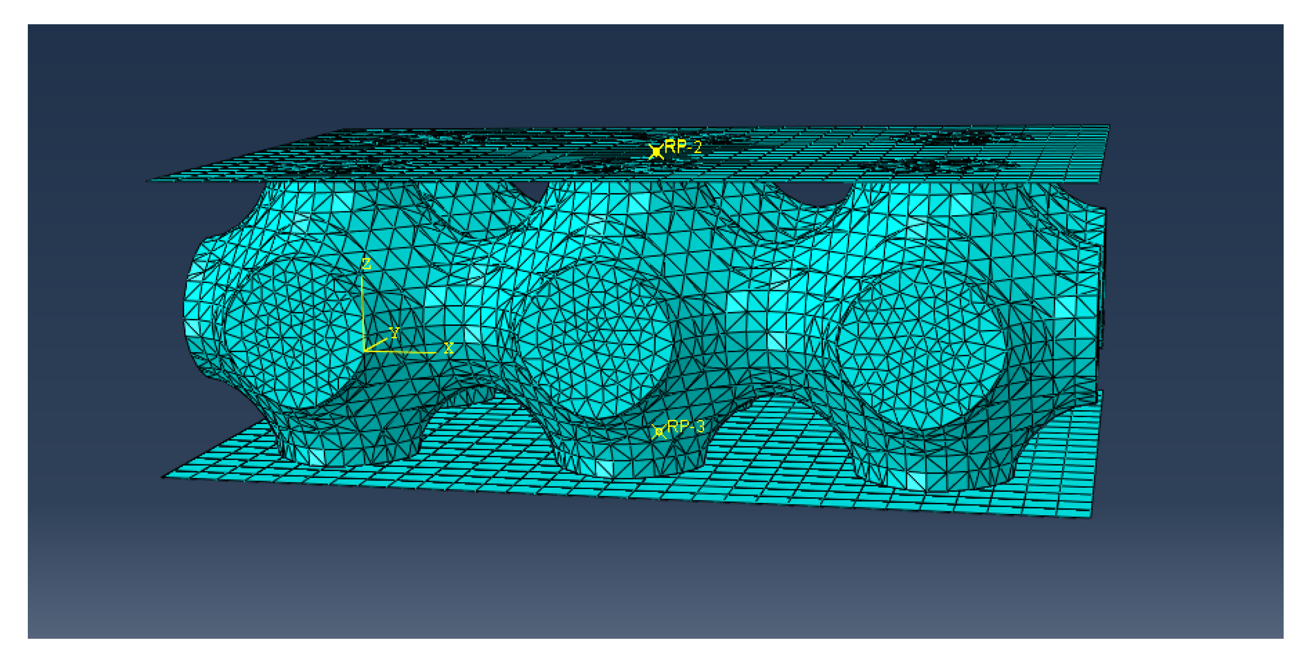
4. Finite Element Modelling of a Proposed Novel SP Sandwich Lattice

Based on the previous results, it is likely to use a SP unit cell for a TPMS sandwich lattice for bridge bearing applications. As a result, the proposed novel model of a 150 mm × 100 mm × 50 mm SP sandwich lattice with at least six unit cell models was modelled (Figure 13) and analysed for its mechanical behaviour compared to both behaviours of the SP and elastomeric block unit cell model. To obtain the mechanical properties of the SP lattice model, the Young’s modulus (Esp) and shear modulus (Gsp) of the schwarz primitive sandwich lattice model were obtained from the slopes of stress–strain relationships for uniaxial compression and combined compression–shear, respectively. In terms of Poisson’s ratio (Vsp), longitudinal and transverse displacement were obtained from the compression sandwich lattice model. Additionally, the computation time required to run a simulation for the SP sandwich lattice model is more than that required for the SP unit cell one due to its greater number of FE meshes. The results of the SP lattice model simulations are discussed in the following section.

5. Results and Discussion

Considering the high performance to weight ratio of the schwarz primitive (SP) unit cell model, the mechanical behaviours of the proposed SP unit cell model under uniaxial compression and combined compression–shear loading were observed and compared to that of the elastomeric block unit cell model, which is commonly known as a rubber unit cell block structure used for a rubber layer. The data collection section shows the comparison of the mechanical responses between a SP unit cell model and an elastomeric block unit cell model as force–displacement curves under uniaxial compression and combined compression–shear loading. It was found that the SP unit cell model appears preferable for use as a sandwich lattice for bridge bearing applications. This is because it can better perform in the horizontal direction, as presented in Figure 10. However, this SP unit cell model has less stiffness in the vertical direction when compared to the other model due to its low stiffness to volume fraction ratio. The combination of at least six unit cells used as a SP lattice can eliminate this drawback by increasing the vertical stiffness discussed in the following part.
To validate the design and manufacturing of a proposed novel SP lattice, a unit cell FEA model was developed for specimens for uniaxial compression. This unit cell model was compared with experimental measurements. The force–displacement relationships obtained from the SP unit cell model (red solid circles) and the two 3D-printed SP specimens (blue and green solid circles) are together in Figure 12. Additionally, it was found that the compressive failure of the SP unit cell is likely to be elastic–plastic due to the geometries, relative density, and material properties. It is clear that the model validation of the SP unit cell model under uniaxial compression observed is excellent within the elastic region and good within the plastic region until the failure point of the structure. It is attributed to this unit cell model that its proposed material model developed in this research for a SP lattice used as bridge bearing is acceptable under uniaxial compression. It is important to mention that in this paper the only compression tests for model validation were conducted because a SP unit cell model using any material or composite material properties first needs to be considered on the compressive behaviour as a bridge bearing to support the weight of a bridge superstructure. This means that this unit cell model is needed to be further developed either in its geometry design or alternative material properties.
In addition, the stress distribution of the SP unit cell model is better than that of the elastomeric block one. As such, the uniform stress distribution of the SP unit cell model occurs rather than random stress distribution in the other one, which can avoid the concentrated stresses shown in Figure 14. Therefore, the finite element analysis of a large-scale model for a SP lattice structure is able to capture the mechanical response and energy abruption of a lattice structure under combined compression–shear loading and uniaxial compression, respectively. Then, as previously mentioned, the proposed novel SP sandwich lattice model under the two loading conditions is run for determining its mechanical properties and energy absorption.
In terms of the performance of the proposed novel SP sandwich lattice model with at least six SP unit cell models under both the identical loading conditions for bridge bearing applications, Figure 15 and Figure 16 present the comparative force–displacement curves of the uniaxial compression and combined compression–shear behaviour of the SP unit cell model, the SP sandwich lattice model, and the elastomeric block unit cell model, respectively. Furthermore, the comparative specific energy absorption per volume curves of all three models are shown in Figure 17. The maximum compressive force of the SP unit cell model is 33 kN at a displacement of 9.3 mm, whilst under combined compression–shear loading, the maximum shear force is 6.6 kN at a displacement of 10 mm. Its failure modes under both loading conditions are elastic–plastic and hysteretic.
It is obvious that the SP sandwich lattice model with at least six SP unit cell models provides more vertical stiffness and shows flexible behaviour under both uniaxial compression and combined compression–shear loading condition, respectively. Additionally, the compression force of the SP sandwich lattice model at the yield point is more than 1.5 and 6 times higher than that of the elastomeric block unit cell model and the SP unit cell model, respectively. However, the maximum shear force of the SP sandwich lattice model at the 10 mm combined compression–shear displacement is more than 1.4 and 18 than that of the elastomeric block unit cell model and the SP unit cell model, respectively. Moreover, among these three structure models, the SP sandwich lattice model exhibits the highest energy absorption per volume after a strain of 0.04 due to the highest strength per weight ratio.
With regard to the mechanical properties of the SP sandwich lattice, its stress–strain curves under uniaxial compression and combined compression–shear loading are obtained from the FEA simulations and the properties are calculated from the slopes of the curves. Table 1 gives the three mechanical properties of the SP sandwich lattice model and Figure 18a,b show its stress–strain curves under compression and combined compression–shear loading, respectively. The Young’s modulus of the SP sandwich lattice model is 1.4 times higher than the shear modulus—and the design requirements of a typical bridge bearing have less shear modulus—but a high Young’s modulus needs to experience/facilitate lateral displacements. Additionally, Figure 19 presents the uniform stress distribution of the combined compression–shear behaviour of the SP sandwich lattice model. Surprisingly, the compressive behaviour is likely to be typically bending-dominated according to [38].
As previously mentioned, it is attributed to the proposed novel 3D-printed SP sandwich lattice model that it is the best performer used as an unbonded bridge bearing under both uniaxial compression and combined compress-shear loading. This novel lattice must be a combination of at least six SP unit cell models in order to improve its mechanical properties and replace the elastomeric layers used in common bride bearing.

6. Conclusions

In this research, a proposed novel TPMS sandwich lattice model with schwarz primitive (SP) unit cell models using a 3D-printed material (UV resin) for meta-functional composite bridge bearing (MFCBB) applications was developed to define its mechanical material properties and the failure modes of the uniaxial compression and combined compression–shear behaviour with the help of the SP and elastomeric block unit cell model. Firstly, three samples of the SP unit cell were designed and fabricated using SLA; then, an elastomeric block unit cell model was designed for the comparative numerical results between both two-unit cell models. These were investigated for their behaviours under uniaxial compression and combined compression–shear loading. Subsequently, the model validation of the numerical predictions of a SP unit cell compared to the experimental results was conducted under conditions of uniaxial compression. The results of the model validation are in excellent agreement within the elastic region.
In addition to the experimental results recorded herein, the compressive mechanical behaviour of the SP unit cell using the UV resin begins with a linear stress–strain dominated by the bending of structs, followed by a long collapse plateau related to the formation of being based on the plastic hinges, brittle crushing, or materials, and ending with the opposing structs touching each other and resulting in densification. The effect of the layer collapse is not observed because its geometry has only one layer as the total height of a typical bridge bearing for Thailand, and highway bridges should not be higher than 45 mm in height [41]. Unlike the SP lattice model, the whole height of the model is slightly more than that of the conventional Thailand bridge bearing, but this can be ignored as its volume fraction sufficiently high to obtain more vertical stiffness under compression. A proposed novel SP sandwich lattice FEA model is then considered to determine its mechanical material properties. Finally, the major conclusions are as follows:
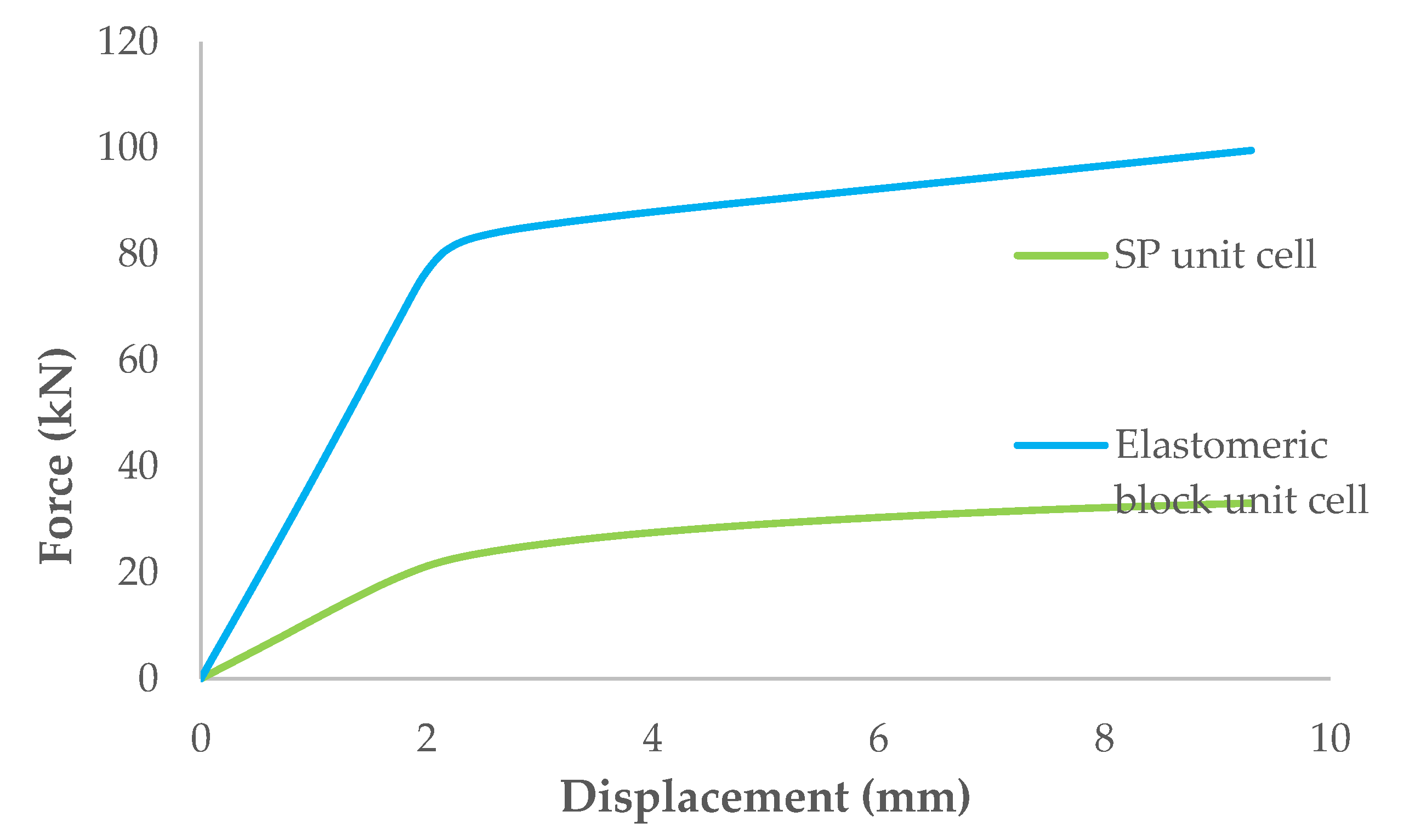
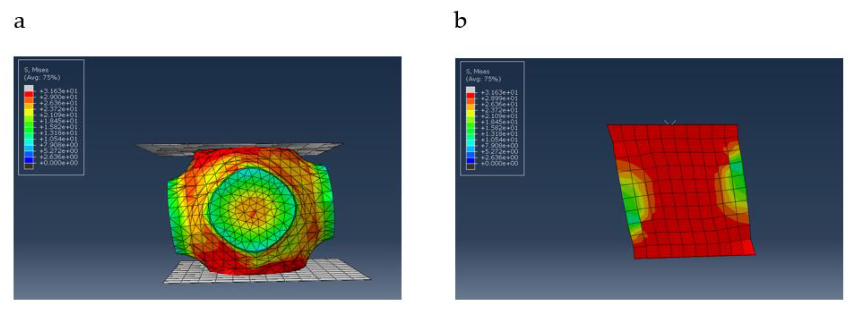
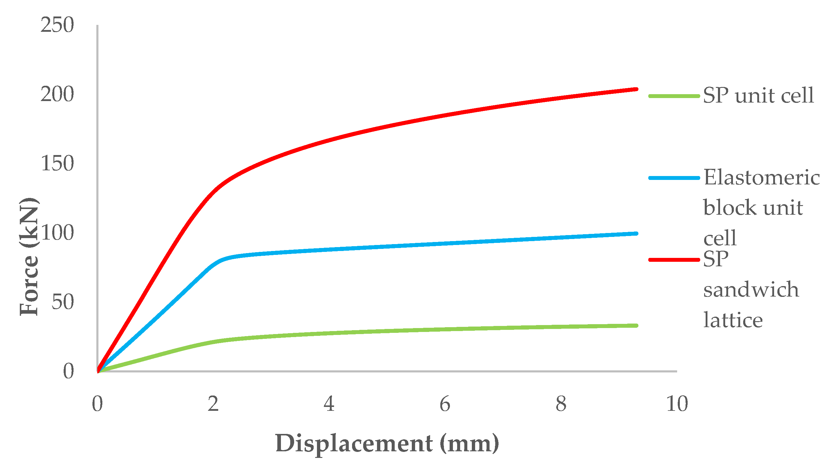
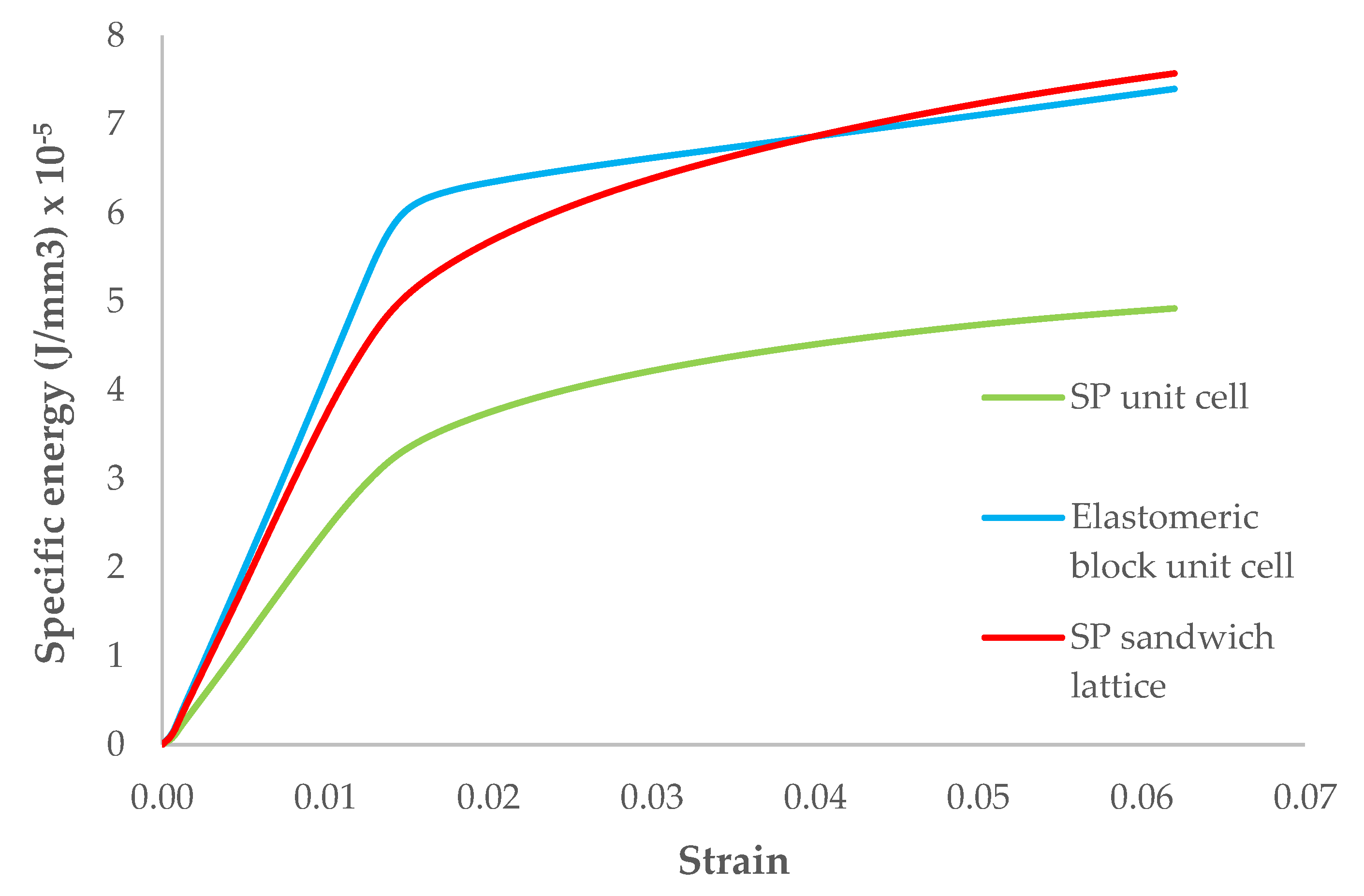
  • The mechanical response of a SP unit cell model under combined compression–shear loading is superior to that of an elastomeric block unit cell model, but it needs an increase in vertical stiffness under uniaxial compression by combining at least six SP unit cell models used as a SP sandwich lattice.
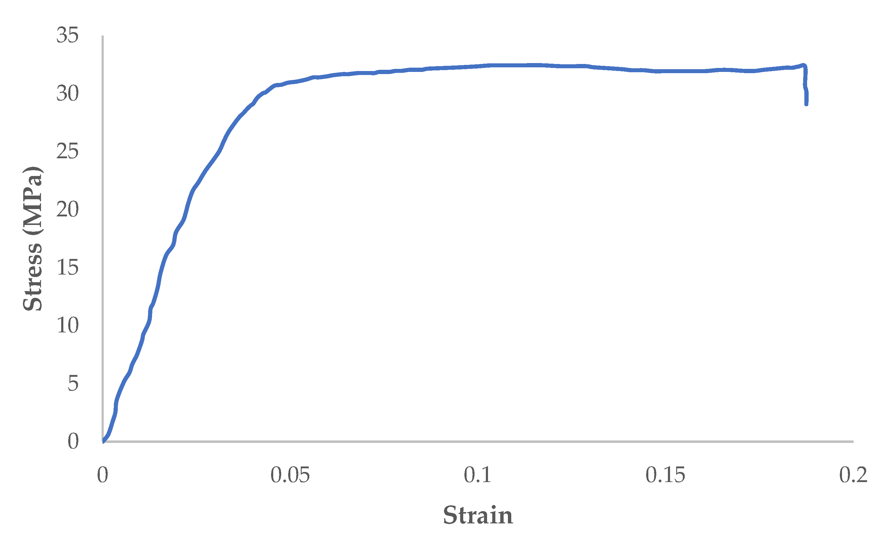
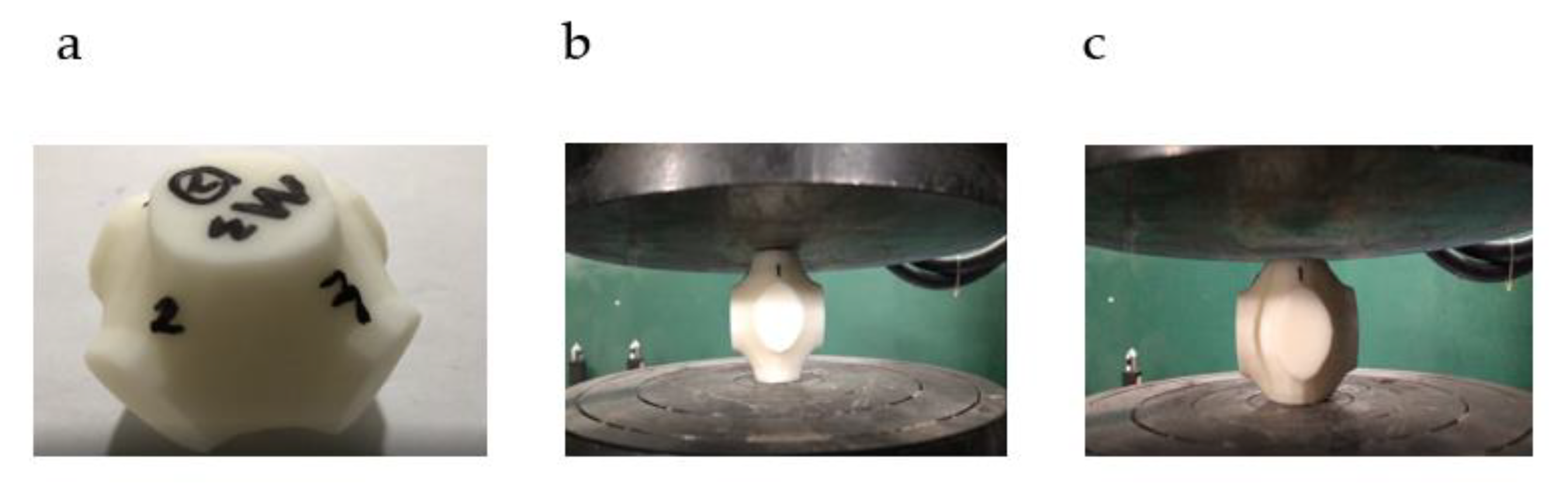
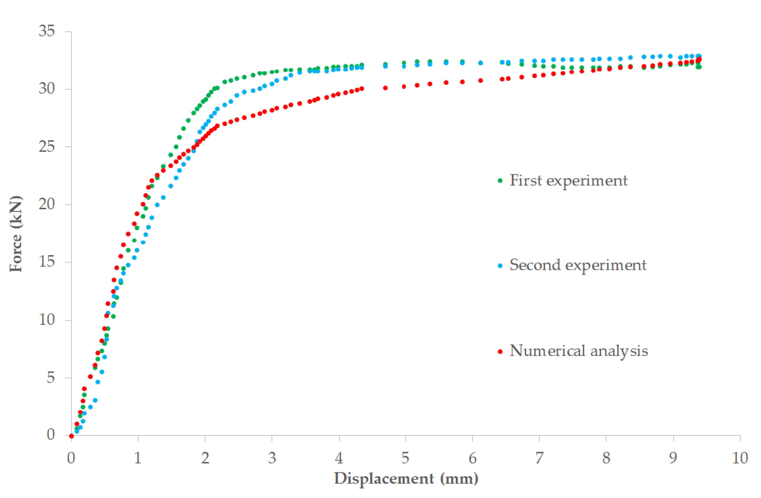
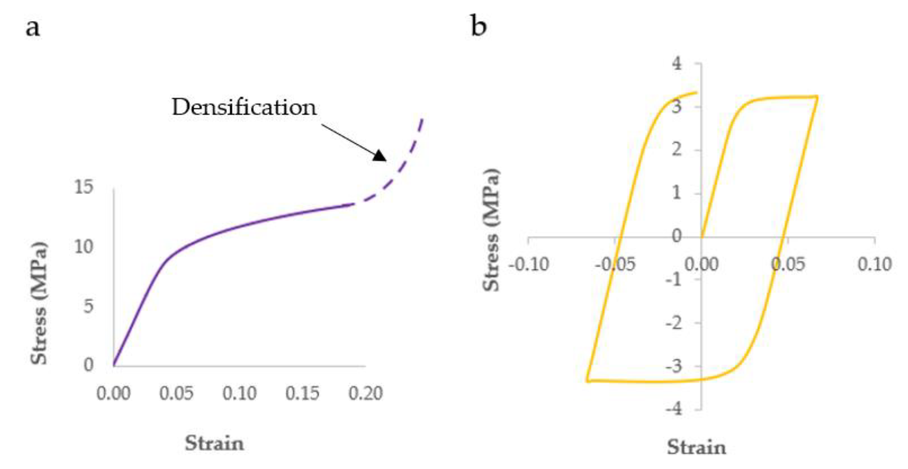
  • During the testing, the three SP unit cell specimens fail in compression at a displacement of 9.3 mm and their failure behaviour is elastic–plastic due to the geometries, relative density, and material properties.
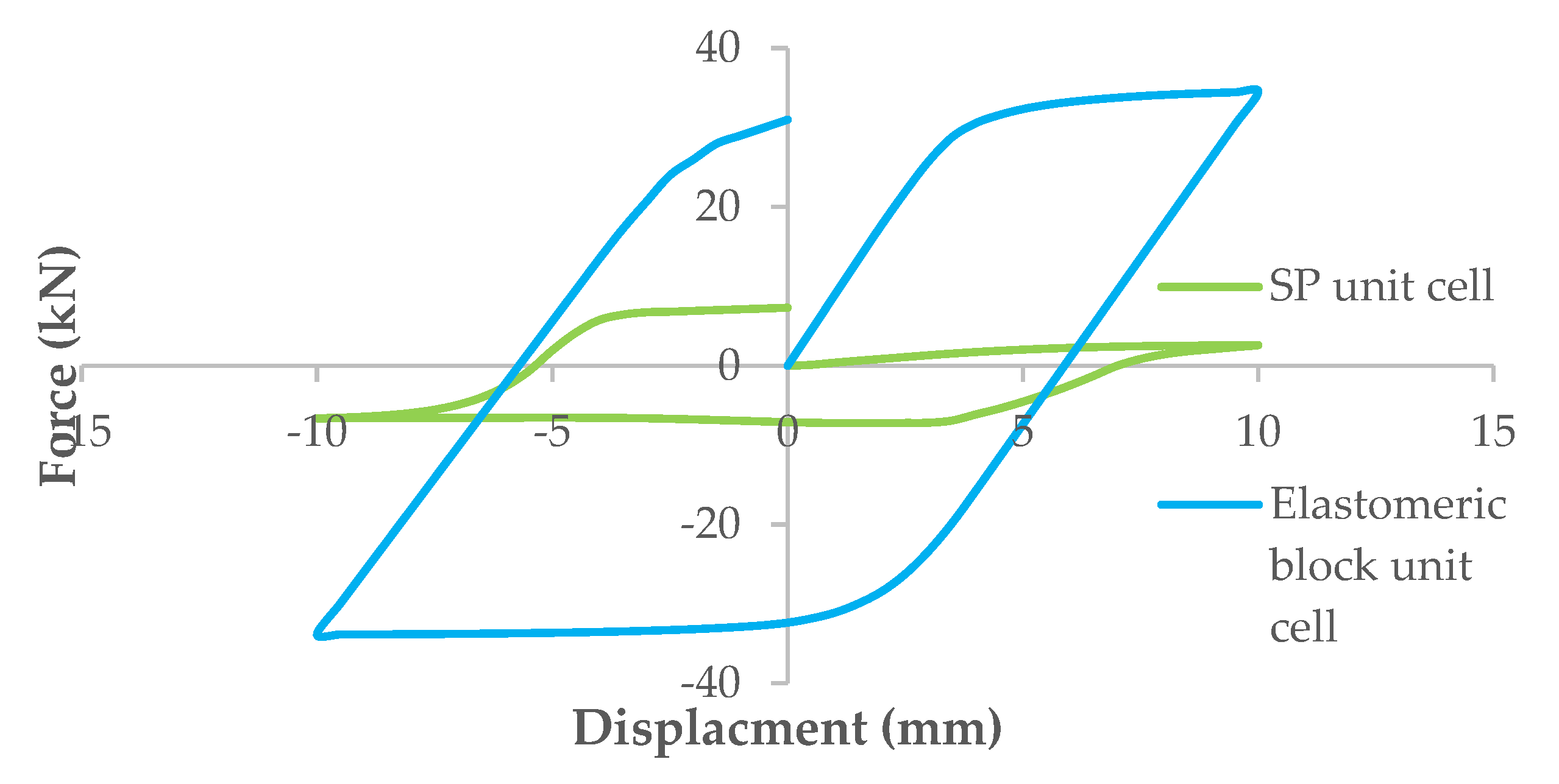
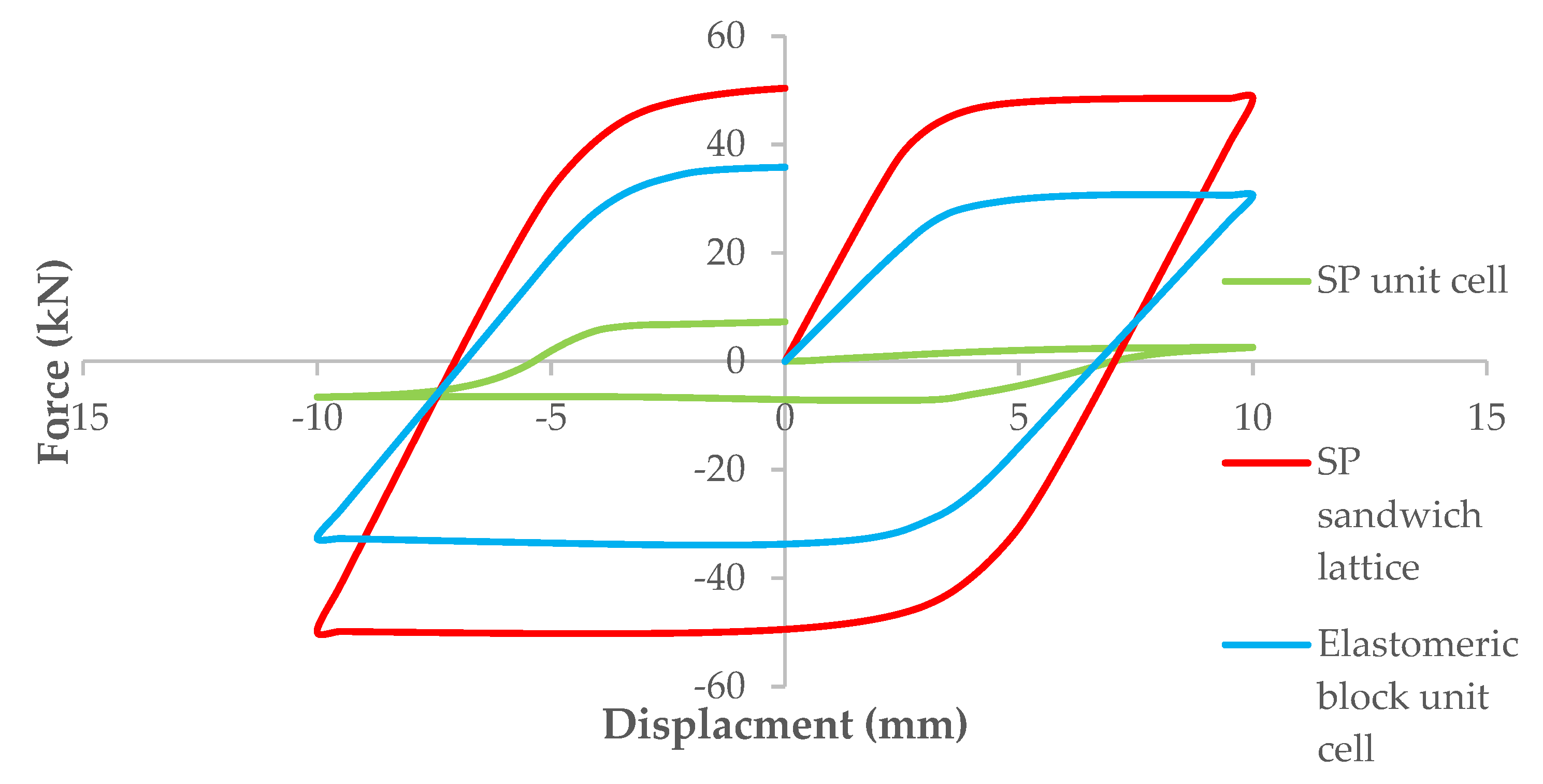
  • The failure mode of the SP unit cell model under combined compression–shear loading is identified as a hysteretic behaviour at a displacement of 10 mm.
  • The proposed novel SP sandwich lattice model exhibits the highest peak force and specific energy absorption under uniaxial compression at a displacement of 9.3 mm. However, under combined compression–shear loading, it still performs well with the highest peak shear force at a displacement of 10 mm.
  • The stress–strain curve of this proposed lattice model under uniaxial compression loading condition is likely a typical bending-dominated one based on a Gibson–Ashby model.
  • For bridge bearing applications, this proposed novel lattice model under compression-shear loading is likely to be stiff in the vertical direction and flexible in the horizontal one, in order to support the superstructure weight and accommodate horizontal displacements, respectively.
The findings in this paper show that a proposed novel schwarz primitive (SP) sandwich lattice model with at least six SP unit cell models can meet the mechanical responses and specific energy absorption under combined compression and uniaxial compression, respectively, as a common elastomeric unit cell requires these properties for bridge bearing applications. Additionally, it was found that the computational time and simulation speed of a SP sandwich lattice model can be significantly reduced from several hours to a couple of minutes. According to the results of this paper, this proposed novel SP sandwich lattice model can be considered a promising alternative for meta-functional composite bridge bearings with a high-performance to density ratio. In future work, we will further investigate the mechanical responses and energy absorption of sheet-based or double TPMS sandwich lattice models, in order to determine their material properties and stress–strain curves under the same loading conditions.

Author Contributions

Conceptualisation, S.K.; methodology, S.K.; software, S.K.; validation, P.S., H.F.; formal analysis, P.S.; investigation, S.K., P.S.; resources, S.K.; writing—original draft preparation, P.S.; writing—review and editing, S.K.; visualisation, P.S.; supervision, S.K.; project administration, S.K.; funding acquisition, S.K. All authors have read and agreed to the published version of the manuscript.

Funding

This research was funded by the European Commission, grant number: H2020-MSCA-RISE No. 691135.

Institutional Review Board Statement

Not applicable.

Informed Consent Statement

Not applicable.

Data Availability Statement

The data that support the findings of this study are available from the corresponding author upon reasonable request.

Acknowledgments

The first author wishes to thank the Royal Thai Government for his Scholarship at the University of Birmingham. The last author wishes to gratefully acknowledge the Japan Society for Promotion of Science (JSPS) for his JSPS Invitation Research Fellowship (long term), Grant No. L15701, at the Track Dynamics Laboratory, Railway Technical Research Institute and at Concrete Laboratory, the University of Tokyo, Tokyo, Japan. The JSPS financially supported this work as part of the research project entitled “Smart and reliable railway infra-structure”. Special thanks are given to the European Commission for H2020-MSCA-RISE Project No. 691135 ‘‘RIS-EN: Rail Infrastructure Systems Engineering Network” (www.risen2rail.eu), accessed 16 August 2021. Partial support from H2020 Shift2Rail Project No. 730849 (S-Code) is acknowledged. In addition, the sponsorships and assistance from LORAM, Network Rail, RSSB (Rail Safety and Standard Board, UK) are highly appreciated.

Conflicts of Interest

The authors declare no conflict of interest.

References

  1. Naeim, F.; Kelly, J. Design of Seismic Isolated Structures: From Theory to Practice; John Wiley & Sons: Hoboken, NJ, USA, 1999. [Google Scholar]
  2. Lee, D.J. Bridge Bearings and Expansion Joints; E & FN Spon: London, UK, 1994. [Google Scholar]
  3. Al-Anany, Y.; Tait, M. Fiber-reinforced elastomeric isolators for the seismic isolation of bridges. Compos. Struc. 2016, 160, 300–311. [Google Scholar] [CrossRef]
  4. Constantinou, M.; Kalpakidis, I.; Filiatrault, A.; Ecker, L.R. LRFD-Based Analysis and Design Procedures for Bridge Bearings and Seismic Isolators. Report No. MCEER-11e0004; Multidisciplinary Center for Earthquake Engineering Research: Buffalo, NY, USA; University at Buffalo: Buffalo, NY, USA; State University of New York: Buffalo, New York, NY, USA, 2011. [Google Scholar]
  5. Al-Anany, Y. Fiber Reinforced Elastomeric Isolators for Bridge Applications. Ph.D. Thesis, McMaster University, Hamilton, ON, Cananda, 2016. [Google Scholar]
  6. Sengsri, P.; Kaewunruen, S. Additive manufacturing meta-functional composites for engineered bridge bearings: A review. Constr. Build. Mater. 2020, 262, 120535. [Google Scholar] [CrossRef]
  7. AASHTO. LRFD Bridge Design Specifications; American Association of State Highway and Transportation Officials: Washington, DC, USA, 2012. [Google Scholar]
  8. Ramberger, G. Structural Bearings and Expansion Joints for Bridges; International Association for Bridges and Structural Engineering (IABSE): Zurich, Switzerland, 2002. [Google Scholar]
  9. Kelly, J.; Konstantinidis, D. Mechanics of Rubber Bearings for Seismic and Vibration Isolation; Wiley: Chichester, UK, 2011. [Google Scholar]
  10. Yasser, M.; Al-Anany, Y.; Michael, J.T. Experimental assessment of utilizing fiber reinforced elastomeric isolators as bearings for bridge applications. Compos. Part B Eng. 2017, 114, 373–385. [Google Scholar] [CrossRef]
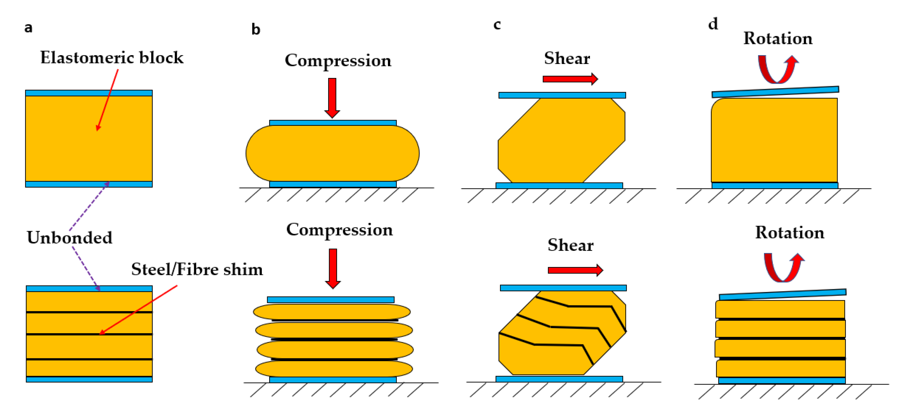
  11. Al-Anany, Y.; Tait, M. A Study on the Rotational Behaviour of Bonded and Unbonded Fiber Reinforced Elastomeric Isolators. In Proceedings of the 11th Canadian Conference on Earthquake Engineering, Victoria, BC, Canada, 21–24 July 2015. [Google Scholar]
  12. Al-Anany, Y.; Tait, M. A numerical study on the compressive and rotational behavior of fiber reinforced elastomeric isolators (FREI). Compos. Struct. 2015, 133, 1249–1266. [Google Scholar] [CrossRef]
  13. Osgooei, P. Advanced Numerical Modeling of Fiber-Reinforced Elastomeric Isolators (FREIs). Ph.D. Thesis, McMaster University, Hamilton, ON, Canada, 2014. [Google Scholar]
  14. Toopchi-Nezhad, H.; Tait, M.; Drysdale, R. Bonded versus unbonded strip fiber reinforced elastomeric isolators: Finite element analysis. Compos Struct. 2011, 93, 850–859. [Google Scholar] [CrossRef]
  15. Sengsri, P.; Kaewunruen, S. Local Failure Modes and Critical Buckling Loads of a Meta-Functional Auxetic Sandwich Core for Composite Bridge Bearing Applications. Appl. Sci. 2021, 11, 10844. [Google Scholar] [CrossRef]
  16. Schoen, H. Infinite Periodic Minimal Surfaces without Selfintersections. NASA TN D-5541; National Aeronautics and Space Administration: Washington, DC, USA, 1970. [Google Scholar]
  17. Schwarz, H.A. Gesammelte Mathematische Abhandlungen; American Mathematical Soc.: New York, NY, USA, 1972. [Google Scholar]
  18. Sajadi, S.M.; Owuor, P.S.; Schara, S.; Woellner, C.F.; Rodrigues, V.; Vajtai, R.; Lou, J.; Galvão, D.S.; Tiwary, C.S.; Ajayan, P.M. Multiscale geometric design principles applied to 3D printed schwarzites. Adv. Mater. 2018, 30, 1704820. [Google Scholar] [CrossRef]
  19. Sun, G.Y.; Jiang, H.; Fang, J.G.; Li, G.Y.; Li, Q. Crashworthiness of vertex based hierarchical honeycombs in out-of-plane impact. Mater. Des. 2016, 110, 705–719. [Google Scholar] [CrossRef]
  20. Yang, Y.; Song, X.; Li, X.; Chen, Z.; Zhou, C.; Zhou, Q.; Chen, Y. Recent progress in biomimetic additive manufacturing technology: From materials to functional structures. Adv. Mater. 2018, 30, 1706539. [Google Scholar] [CrossRef]
  21. Yan, C.; Hao, L.; Hussein, A.; Raymont, D. Evaluations of cellular lattice structures manufactured using selective laser melting. Int. J. Mach. Tools Manuf. 2012, 62, 32–38. [Google Scholar] [CrossRef]
  22. Yan, C.; Hao, L.; Hussein, A.; Young, P. Ti-6Al-4V triply periodic minimal surface structures for bone implants fabricated via selective laser melting. J. Mech. Behav. Biomed. Mater. 2015, 51, 61–73. [Google Scholar] [CrossRef] [PubMed] [Green Version]
  23. Yan, C.; Hao, L.; Hussein, A.; Young, P.; Raymont, D. Advanced lightweight 316L stainless steel cellular lattice structures fabricated via selective laser melting. Mater. Des. 2014, 55, 533–541. [Google Scholar] [CrossRef] [Green Version]
  24. Mazur, M.; Leary, M.; Sun, S.; Vcelka, M.; Shidid, D.; Brandt, M. Deformation and failure behaviour of Ti-6Al-4V lattice structures manufactured by selective laser melting (SLM). Int. J. Adv. Manuf. Technol. 2016, 84, 1391–1411. [Google Scholar] [CrossRef]
  25. Al-Ketan, O.; Adel Assad, M.; Abu Al-Rub, R.K. Mechanical properties of periodic interpenetrating phase composites with novel architected microstructures. Compos. Struct. 2017, 176, 9–19. [Google Scholar] [CrossRef]
  26. Smith, M.; Guan, Z.; Cantwell, W.J. Finite element modelling of the compressive response of lattice structures manufactured using the selective laser melting technique. Int. J. Mech. Sci. 2013, 67, 28–41. [Google Scholar] [CrossRef]
  27. Zhang, L.; Feih, S.; Daynes, S.; Chang, S.; Wang, M.Y.; Wei, J.; Lu, W.F. Energy absorption characteristics of metallic triply periodic minimal surface sheet structures under compressive loading. Addit. Manuf. 2018, 23, 505–515. [Google Scholar] [CrossRef]
  28. Aremu, A.O.; Maskery, I.; Tuck, C.A. Comparative finite element study of cubic unit cells for selective laser melting. Self-supporting unit cells. In Proceedings of the 2014 International Solid Freeform Fabrication Symposium, Coventry, UK, 4–6 August 2014; pp. 1238–1249. [Google Scholar]
  29. Selo, R.R.J.; Catchpole-Smith, S.; Maskery, I.; Ashcroft, I.; Tuck, C. On the thermal conductivity of AlSi10Mg and lattice structures made by laser powder bed fusion. Addit. Manuf. 2020, 34, 101214. [Google Scholar] [CrossRef]
  30. Simsek, U.; Arslan, T.; Kavas, B.; Gayir, C.E.; Sendur, P. Parametric studies on vibration characteristics of triply periodic minimum surface sandwich lattice structures. Int. J. Adv. Manuf. Technol. 2020, 115, 675–690. [Google Scholar] [CrossRef]
  31. Habib, F.N.; Iovenitti, P.; Masood, S.H.; Nikazad, M. Cell geometry effect on in-plane energy absorption of periodic honeycomb structures. Int. J. Adv. Manuf. Tecnol. 2018, 94, 2369–2380. [Google Scholar] [CrossRef]
  32. Sarvestani, H.Y.; Akbarzadeh, A.H.; Niknam, H.; Hermenean, K. 3D printed architected polymeric sandwich panels: Energy absorption and structural performance. Compos. Struct. 2018, 200, 886–909. [Google Scholar] [CrossRef]
  33. Sugiyama, K.; Matsuzaki, R.; Ueda, M.; Todoroki, A.; Hirano, Y. 3D printing of composite sandwich structures using continuous carbon fiber and fiber tension. Compos. Part A-Appl. S. 2018, 113, 114–121. [Google Scholar] [CrossRef]
  34. Ling, C.; Cernicchi, A.; Gilchrist, M.D.; Cardiff, P. Mechanical behaviour of additively-manufactured polymeric octet-truss lattice structures under quasi-static and dynamic compressive loading. Mater. Des. 2019, 162, 106–118. [Google Scholar] [CrossRef]
  35. Abueidda, D.W.; Elhebeary, M.; Shiang, C.S.; Pang, S.Y.; Abu, A.; Jasiuk, I.M. Mechanical properties of 3D printed polymeric gyroid cellular structures: Experimental and finite element study. Mater. Des. 2019, 165, 107597. [Google Scholar] [CrossRef]
  36. Askarinejad, S.; Choshali, H.A.; Flavin, C.; Rahbar, N. Effects of tablet waviness on the mechanical response of architected multilayered materials: Modeling and experiment. Compos. Struct. 2018, 195, 118–125. [Google Scholar] [CrossRef]
  37. Sang, L.; Han, S.; Peng, X.; Jian, X.; Wang, J. Development of 3D-printed basalt fiber reinforced thermoplastic honeycombs with enhanced compressive mechanical properties. Compos. Part A Appl. Sci. Manuf. 2019, 125, 105518. [Google Scholar] [CrossRef]
  38. Ashby, M.F.; Medalist, R.M. The mechanical properties of cellular solids. Metall. Trans. 1983, 14, 1755–1769. [Google Scholar] [CrossRef]
  39. Triply Periodic Level Surfaces, Archived. 2019. Available online: http://www.msri.org/publications/sgp/jim/geom/level/library/triper/index.html (accessed on 28 August 2021).
  40. Abaqus CAE User’s Guide; DS Simulia Abaqus: Providence, RI, USA, 2017.
  41. Standard Drawings for Highway Design and Construction 2015 Revision, Thai Version. 2015. BP-102. Available online: http://www.doh.go.th/uploads/tinymce/service/bid/doc_bid/STANDARD%20DRAWING%202015%20EDITION_2018.pdf (accessed on 18 December 2021).
Figure 1. (a) Unloaded, (b) compressive, (c) lateral, and (d) rotational deformation patterns of a non-reinforced elastomeric bridge bearing and an unbonded fibre/steel-reinforced elastomeric bridge bearing, respectively.
Jcs 06 00071 g001
Figure 2. Various lattice structures used for many applications in engineering.
Jcs 06 00071 g002
Figure 3. Typical stress–strain curves of (a) a bending-dominated lattice structure and (b) a stretch-dominated lattice structure under uniaxial compression.
Jcs 06 00071 g003
Figure 4. Schwarz primitive unit cell CAD model.
Jcs 06 00071 g004
Figure 5. Finite element models of (a) a schwarz primitive unit cell and (b) elastomeric block unit cell in Abaqus.
Jcs 06 00071 g005
Figure 6. Mesh sensitivity of a schwarz primitive unit cell (50 × 50 × 50) mm, for a mesh size from 5 (coarse) to 0.75 (fine) mm.
Jcs 06 00071 g006
Figure 7. Boundary conditions of (a) a schwarz primitive unit cell FEA model and (b) an elastomeric block unit cell FEA model under combined compression–shear loading.
Jcs 06 00071 g007
Figure 8. Proposed material properties from compressive stress–strain relationships used in numerical analysis.
Jcs 06 00071 g008
Figure 9. Comparative force–displacement curves of both the SP unit cell FE model and elastomeric block unit cell FE model under uniaxial compression loading.
Jcs 06 00071 g009
Figure 10. Comparative force–displacement curves of both the SP unit cell FE model and elastomeric block unit cell FE model under combined compression–shear loading.
Jcs 06 00071 g010
Figure 11. Experimental procedures: (a) a prepared specimen; (b) uniaxial compression test within the elastic–plastic region; and (c) uniaxial compression test at the failure.
Jcs 06 00071 g011
Figure 12. Comparison of force–displacement curves of the SP unit cell between numerical and experimental results.
Jcs 06 00071 g012
Figure 13. Full-FEA simulations of the proposed novel sandwich lattice model under uniaxial compression and combined compression–shear loading.
Jcs 06 00071 g013
Figure 14. (a) Uniform and (b) random stress distribution of the combined compression–shear behaviours of the SP unit cell model and the elastomeric block unit cell model, respectively.
Jcs 06 00071 g014
Figure 15. Force–displacement curves of all three models subjected to uniaxial compression loading.
Jcs 06 00071 g015
Figure 16. Force–displacement curves of all three models subjected to combined compression–shear loading.
Jcs 06 00071 g016
Figure 17. Energy absorption per volume of all three models subjected to uniaxial compression loading.
Jcs 06 00071 g017
Figure 18. Representative stress–strain curves of the proposed novel SP sandwich lattice model subjected to (a) uniaxial compression and (b) combined compression–shear loading, respectively.
Jcs 06 00071 g018
Figure 19. Uniform stress distribution of the combined compression–shear behaviour of the proposed novel SP sandwich lattice model.
Jcs 06 00071 g019
Table 1. Mechanical properties of the proposed novel SP sandwich lattice model subjected to combined compression–shear loading.
Proposed MaterialYoung’s Modulus, Esp (MPa)Shear Modulus, Gsp (MPa)Poisson’s Ratio, VspTotal Absorption Energy (J)
UV resin213.56153.330.362153.97
Publisher’s Note: MDPI stays neutral with regard to jurisdictional claims in published maps and institutional affiliations.

