Article

Toughening and Healing of CFRPs by Electrospun Diels–Alder Based Polymers Modified with Carbon Nano-Fillers

by
Athanasios Kotrotsos
1,
Constantinos Rouvalis
1,
Anna Geitona
1 and
Vassilis Kostopoulos
1,2,*
1
Department of Mechanical Engineering and Aeronautics, University of Patras, GR-26504 Patras, Greece
2
Foundation of Research and Technology, Institute of Chemical Engineering Sciences (FORTH/ICE-HT), Stadiou Str., GR-26504 Patras, Greece
*
Author to whom correspondence should be addressed.
J. Compos. Sci. 2021, 5(9), 242; https://doi.org/10.3390/jcs5090242
Submission received: 5 August 2021 / Revised: 7 September 2021 / Accepted: 8 September 2021 / Published: 10 September 2021
(This article belongs to the Special Issue Carbon-Based Polymer Nanocomposites)

Abstract

:
In the present investigation, thermo-reversible bonds formed between maleimide and furan groups (Diels–Alder (DA)-based bis-maleimides (BMI)) have been generated to enable high-performance unidirectional (UD) carbon fiber-reinforced plastics (CFRPs) with self-healing (SH) functionality. The incorporation of the SH agent (SHA) was performed locally, only in areas of interest, with the solution electrospinning process (SEP) technique. More precisely, reference and modified CFRPs with (a) pure SHA, (b) SHA modified with multi-walled carbon nano-tubes (MWCNTs) and (c) SHA modified with graphene nano-platelets (GNPs) were fabricated and further tested under Mode I loading conditions. According to experimental results, it was shown that the interlaminar fracture toughness properties of modified CFRPs were considerably enhanced, with GNP-modified ones to exhibit the best toughening performance. After the first fracture and the activation of the healing process, C-scan inspections revealed, macroscopically, a healing efficiency (H.E.) of 100%; however, after repeating the tests, a low recovery of mechanical properties was achieved. Finally, optical microscopy (OM) examinations not only showed that the epoxy matrix at the interface was partly infiltrated by the DA resin, but it also revealed the presence of pulled-out fibers at the fractured surfaces, indicating extended fiber bridging between crack flanks due to the presence of the SHA.

1. Introduction

Fiber-reinforced polymer composites (FRPs) are leading candidates as component materials to improve the efficiency and sustainability of many forms of transport due to their lightweight, high specific-strength and stiffness values. However, a primary limitation of composites is their susceptibility to micro-damage, the poor interlaminar fracture toughness and interlaminar shear strength that make them prone to delaminations during their service life [1]. Based on these, it is necessary to consider new concepts in maintenance domain. To meet the need for reduction in maintenance costs, an innovative robotized inspection and repair concept is required, together with smart designs and new hybrid multifunctional material concepts. This challenging situation acted as an inspiration for seeking new repair methods (further to the typical scarfing and stepping ones that are used in composites) that are cheaper and applicable at the early stages of damage evolution.
An emerging approach called “Self-healing (SH) materials” has been proposed but has not yet been applied to commercial composites [2]. This smart technology aims to repair damages in situ and autonomously, thus leading to an extension of the effective life-span of the composite structures. SH of composites promises to mitigate the importance for detecting damage and to reduce the frequency of scheduled inspections. SH technologies could extend the service life and reliability of epoxy resins and composites. Based on the literature, a typical way to classify SH systems is divide them in (a) autonomous SH (extrinsic type) [3] and (b) non-autonomous SH (intrinsic type) [4]. Non-autonomous SH seems to be the most promising approach for SH composites, as specific reversible bonds are introduced into epoxide networks [5,6,7]. This approach allows the healing to be unlimited as no chemicals are consumed, if compared with the autonomous SH mechanism (capsule- or vascular-based network) [4]. Non-autonomous SH technology has been demonstrated through self-healable polymers that are based on supramolecular chemistries (i.e., hydrogen bonding, ionomeric bonding, metal–ligand coordination, etc.) [8,9,10,11], covalent bonding (i.e., common thermoplastics) [12,13,14] and special covalent bonding (i.e., Diels–Alder (DA)-based mechanism bis-maleimide (BMI) polymers) [15,16]. For SH technology related to the intrinsic type, the activation of the healing process is performed through the heating of materials at temperatures close to or higher than the self-healing agent (SHA) melting point (Tm) [5,6,7,8,9,10,11,12,13,14,15,16].
DA-based BMI materials exhibit healing functionalities on a polymer level due to their thermally reversible nature, while presenting a resin-type behavior [15]. During the last years, a wide range of publications related to the use of SHAs that are based on the DA reaction mechanism has been released [6,17,18,19]. In [6], Kostopoulos et al. impregnated dry carbon-fiber fabrics with DA-based SH resin with the aim to modify the mid-plane area of high-performance carbon fiber-reinforced plastics (CFRPs). The final composites not only presented enhanced Mode I fracture toughness properties, but also acceptable healing behavior after the activation of the healing process. In [17], a DA-based SHA was also utilized to modify CFRPs containing holes, which further tested under tension–tension fatigue conditions. Modified CFRPs not only exhibited comparable tensile properties but the fatigue life was also extended by 75%. In [18], the authors investigated the effect of SHA concentration and curing cycle of DA-based CFRPs on mechanical and healing performance. SEP technique seems to be very promising for composites modification. Recently [18], CFRPs intended for low velocity impact tests were locally modified with a DA-based SHA through the SEP technique. Modified samples exhibited no degradation effects due to the incorporation of the SHA, while the induced damage due to LVI was entirely healed after the activation of the healing process. Finally, the damage repair obtained via healing process improved the residual mechanical properties of the damaged composites.
In the current investigation, an SHA, enabled or not by nanotechnology, was incorporated locally into composite structures to enable them with healing functionality. More precisely, reference CFPRs (without SHA) and modified ones, with (a) pure SHA, (b) SHA and multi-walled carbon-nanotubes (MWCNTs) and (c) SHA and graphene nano-platelets (GNPs), were fabricated and tested under Mode I loading conditions. This work builds on and is complemented by other studies [6,16,17,18] by the authors in which the same or a similar type of SHA has been utilized for modification of composite structures in different ways and tested under various experimental conditions. The present work took a step forward, as the DA-based SHA was further modified by nano-fillers (MWCNTs and GNPs) at the amount of 1 wt% while homogeneously distributed onto the targeted area of pre-preg plies prior manufacturing by the solution electrospinning process (SEP) technique. According to experimental results, it was shown that, by the incorporation of all SHA systems, the Mode I fracture toughness properties were considerably increased with SHA- and GNP-modified ones to exhibit the best toughening performance. After the first fracture-modified CFRPs passed through the healing cycle, they were tested again under the same testing conditions to evaluate the healing performance. Finally, three-point bending tests (3PB) were performed to investigate the effect of the SHA on the in-plane mechanical properties of the CFRP, while optical microscopy (OM) examinations of cross-sections and fractured surfaces were performed to investigate the involved failure mechanisms.

2. Materials and Methods

2.1. Materials

The composite materials utilized in the current study were fabricated using a commercial unidirectional (UD) carbon fibre-epoxy pre-preg tape (identification code: CE-1007 150-38). The commercial pre-preg tape was supplied by SGL Group, Germany. The utilized maleimide oligomers, with an approximate molecular weight of 1700 Da (BMI-1700), were supplied by Designer Molecules (San Diego, CA, USA). BMI-1700 is hydrophobic, with high decomposition temperature (above 400 °C) and it is soluble in most aromatic and aliphatic solvents. The reactants furfuryl glycidylether and furfuryl amine, which were utilized for trifurane (TF) synthesis, were purchased from Sigma-Aldrich Chemicals (St. Louis, MO, USA). All reagents were used as received and no further purification occurred. The tetrahydrofurane (THF) solvent, which was used as SEP solvent, was supplied by Honeywell Inc. (Charlotte, NC, USA). The obtained MWCNTs (identification code: NC7000) were supplied by Nanocyl, Sambreville, Belgium, and were produced via the catalytic chemical vapor deposition process. The typical MWCNTs diameter was 10–20 nm and their aspect ratio spans were 50–100. The obtained GNPs had lateral dimensions of 1–2 μm, average thickness ≤ 4 nm, surface area ≥ 750 m2/gr and purity ≥ 99% and were supplied by Cheap Tubes Inc., Cambridgeport, Cambridge, MA, USA.

2.2. Electrospinning Process and Preparation of the Modified Pre-Preg Plies

The incorporation of the SHA was conducted by SEP. The information that is related to the SEP technique and modification procedure by SHA of the pre-preg plies is provided in a recent paper by the authors [19] and is not included in this manuscript. Prior to SEP, nanofillers were incorporated into the fabricated solution and then sonicated using the Bandelin electronic sonicator apparatus, which was made in Berlin, Germany. During the sonication process, a frequency of 35 kHZ was applied to the solution for 3 h and had the aim to achieve homogeneity by breaking down potential nanofiller agglomerates.

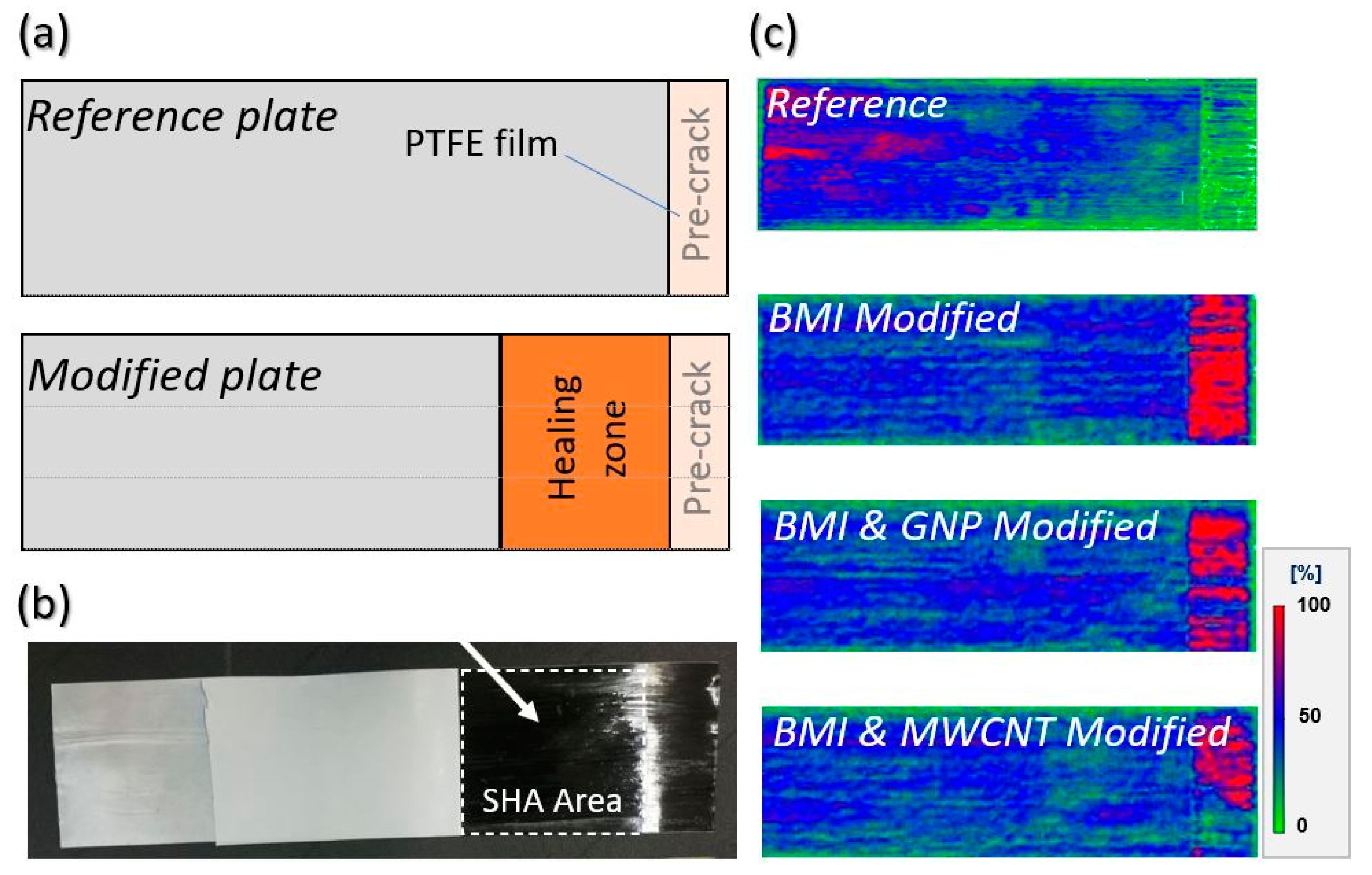
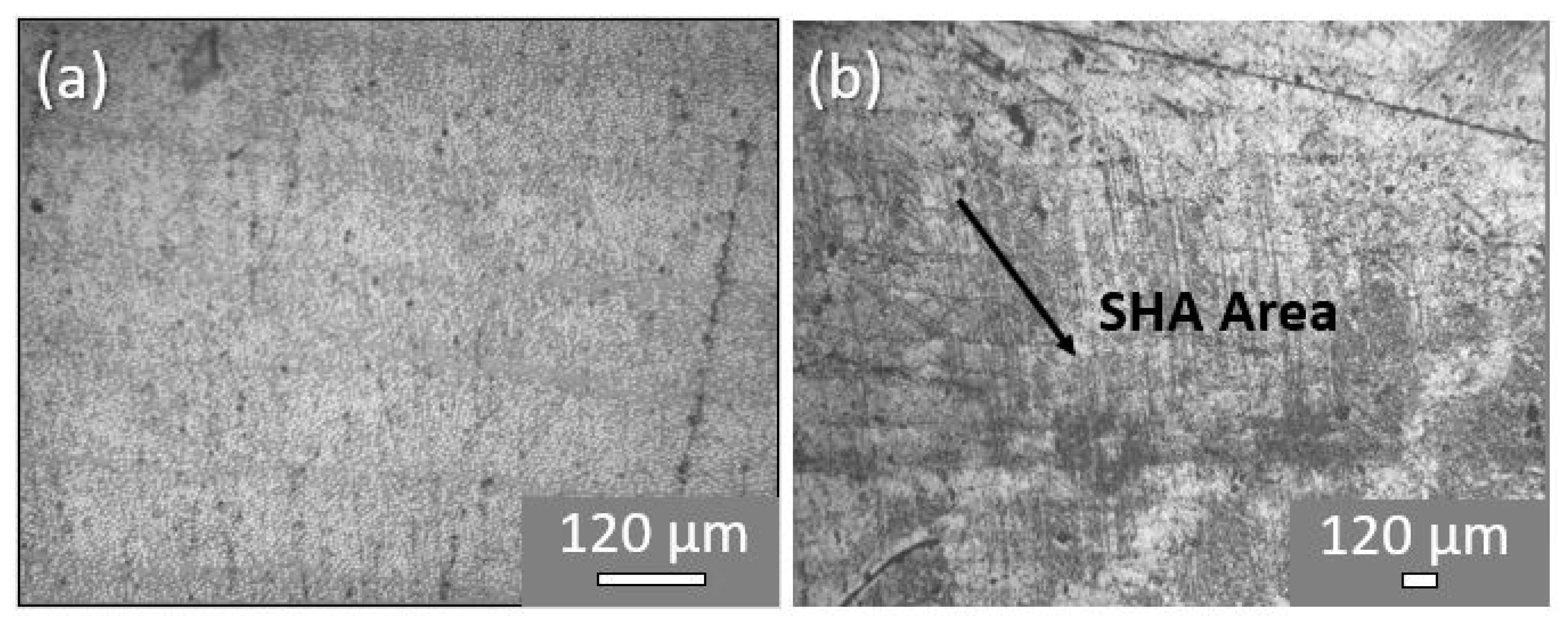
2.3. Composites Manufacturing, Quality Control and Optical Microscopy Examinations
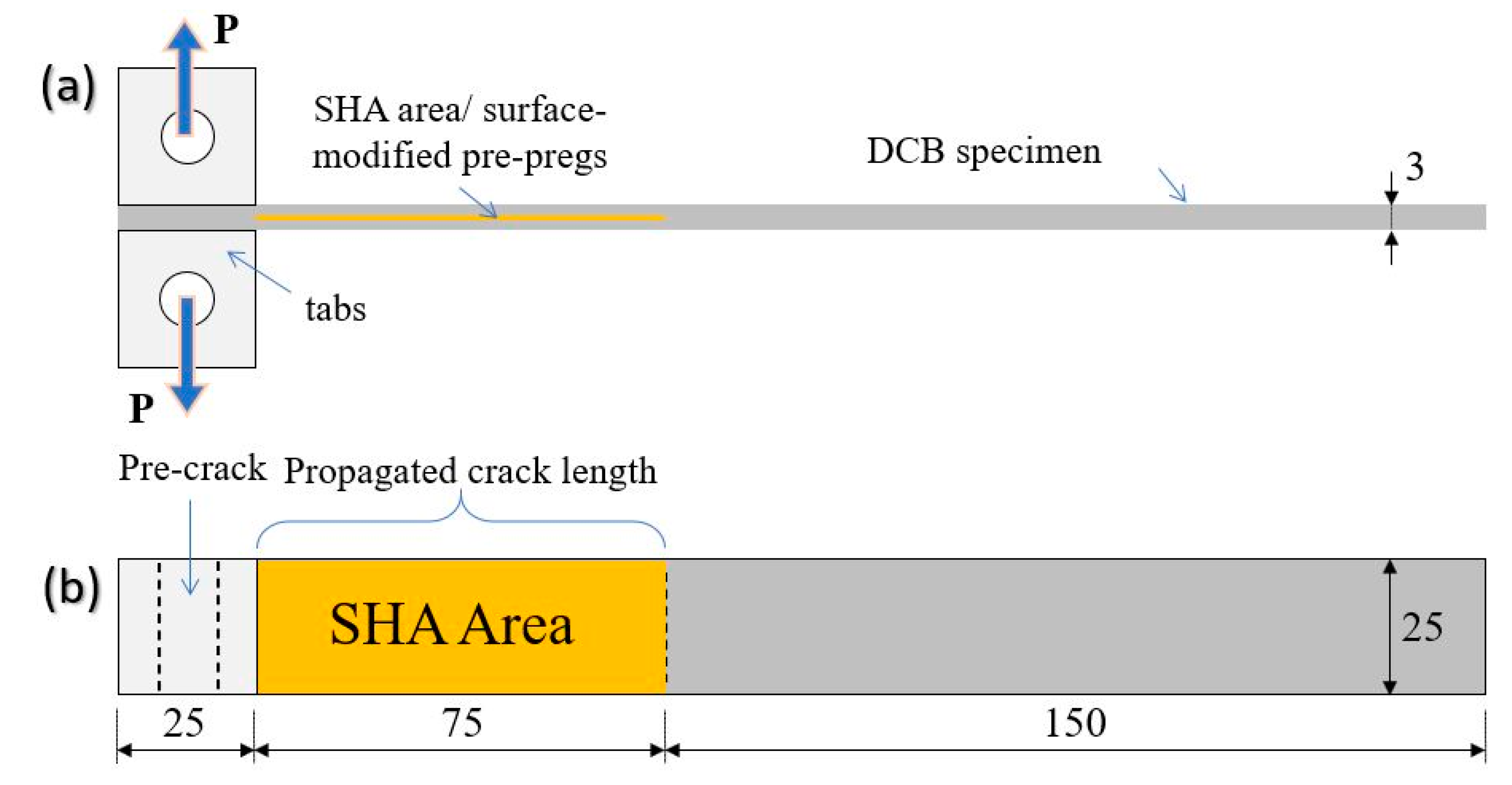
For the manufacturing of the composites, pre-preg and autoclave technologies were utilized. Four types of laminated plates with 22 UD pre-pregs were prepared: the reference laminate and three modified laminates containing pure SHA, SHA with 1 wt% MWCNTs and SHA with 1 wt% GNPs into their mid-thickness area (5 surface-modified pre-preg plies). During SEP, the deposited SHA onto the surface of the pre-pregs created an “interleaf” with the aim to provide the healing functionality. Figure 1a,b illustrates the design of the fabricated plates and a representative pre-preg tape with modified surface by electrospun SHA, respectively. Three plates for each material set were manufactured with the dimensions 270 × 60 × 3 mm3 that led to 6 double cantilever beam (DCB) samples (2 samples per CFRP plate) having final dimensions of (250 × 25 × 3) mm3 and whose geometry is illustrated in Figure 2, taking into consideration specifications of the AITM 1.0005 standard of Airbus [20]. The final fiber volume fraction of all composites (Vf) was calculated to be close to 60 ± 2% without the incorporation of the SHA affecting the thickness of the final composite. Five samples per material type were tested under Mode I loading conditions (prior and after healing activation), while one sample was indented for cross-sectional OM examinations. During manufacturing, two polytetrafluoroethylene (PTFE) sheets with 13 μm thickness were positioned in the mid-thickness area to create an artificial pre-crack, according to the utilized standard specifications.
Following the lamination process, the composites structures were cured in an autoclave. The applied curing profile was 100 °C of applied temperature, under 4 bar of applied pressure for a period of 5 h. After the curing process, all manufactured CFRP plates were ultrasonically scanned, using a physical acoustics corporation UT C-scan system with a 5 MHz transducer. Figure 1c provides C-scan inspections for all material sets manufactured. Finally, the OM examination of their morphology was conducted using an SINOWON IMS-300 microscope.

2.4. Mode I Testing

Quasi-static Mode I interlaminar fracture toughness tests were performed using an Instron Universal testing machine equipped with a 5 kN load cell at room temperature (RT) conditions. The tests were performed according to the AITM 1.0005 standard of Airbus [20]. Figure 2 illustrates the DCB specimen geometry and experimental set-up. The information on the tests is presented in a recent paper by the authors [6] and is not included in this paper.

2.5. Healing Procedure and Healing Efficiency Calculation

After Mode I testing, delaminated samples were exposed to a healing cycle of controlled heating via thickness pressure using a heat-press machine. The healing cycle comprised a 30 min dwell at 130 °C under 1 kN loading that resulted in 0.16 bar pressure. The healing characteristics were selected to be sure that the SHA would have been able to flow and fill the delaminated area. Then, all CFRPs were left to cool down until they reached RT. After the healing process, C-scan inspections of the CFRPs were repeated. The healing efficiency (H.E.) calculations are based on Equation (1):
H . E . = S healed S damaged · 100 ( % )
where Sdamaged and Shealed are the values of the property (in our case the damage area) prior and after the healing process, respectively.

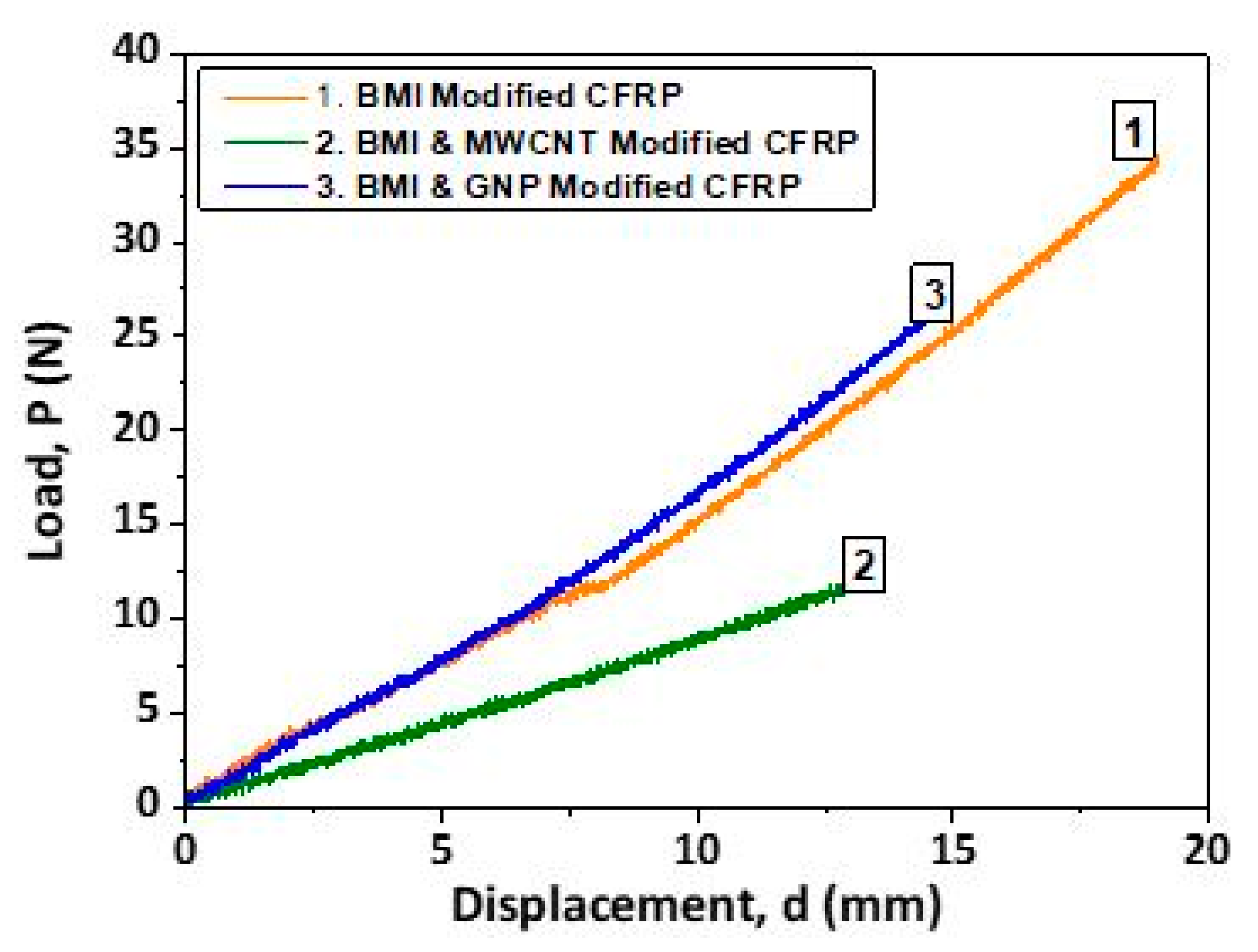
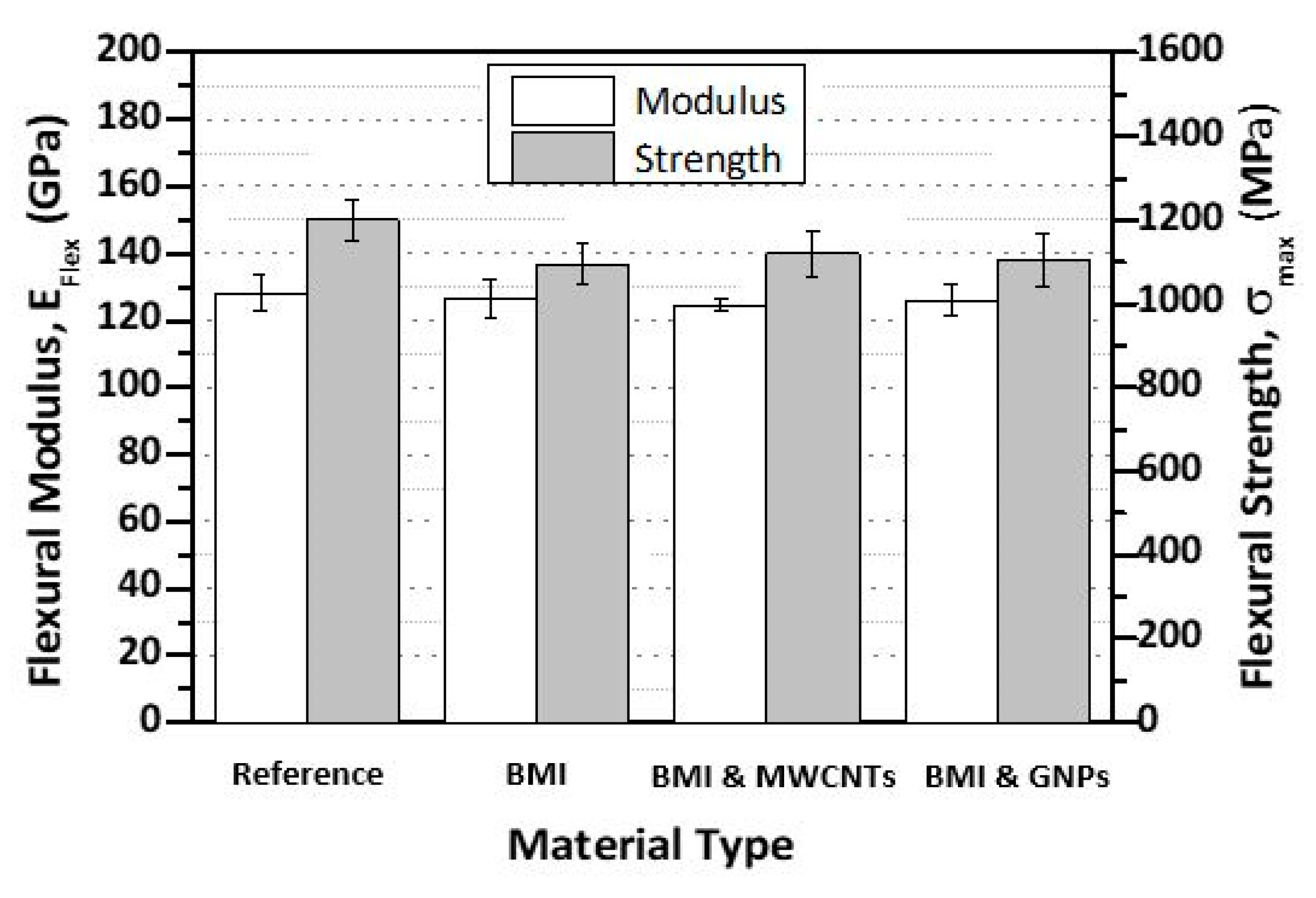
2.6. Three-Point Bending Testing

Three-point bending tests were carried out following the ASTM D7264M-07 [21] in an Instron test frame. Test informations have already been reported in Ref. [12].

3. Results and Discussion

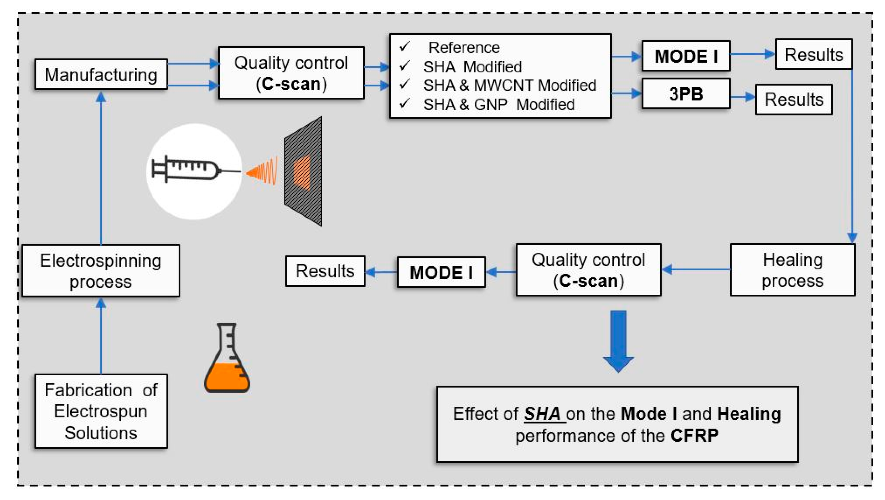
3.1. Test Program Outline

The SHA reactants (maleimide oligomers and TF in stoichiometric analogy) were dissolved into THF solvent in the amount of 15 wt% to fabricate the electrospun solution, with the aim to integrate it into the composite structure by SEP [19]. In the case of nano-modified samples, 1 wt% of nano-filler was dissolved into the SHA (either MWCNTs or GNPs). More precisely, the steps followed in the current investigation were the following: (a) fabrication of the electrospun solutions; (b) integration of the SHA systems onto CFRP pre-pregs locally (only at areas of interest), that could be considered as interlayers; (c) manufacturing of all CFRP types and curing of them, that would further contribute to SHA synthesis (cross-linking of DA-based material due to heat) [19]; (d) quality control of the fabricated CFRP plates; (e) execution of Mode I fracture toughness and 3PB tests; (f) activation of healing process and repeating of Mode I tests under the same conditions. The steps that were followed are provided in Figure 3.

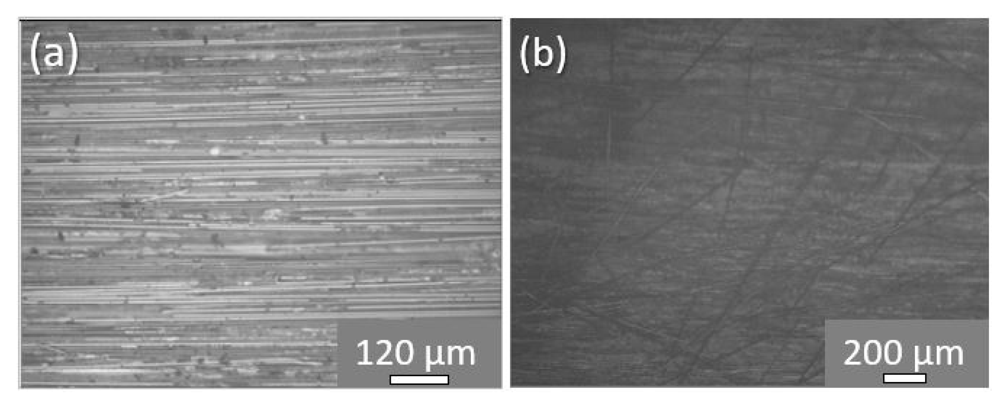
3.2. Composites’ Manufacturing and Quality Issues
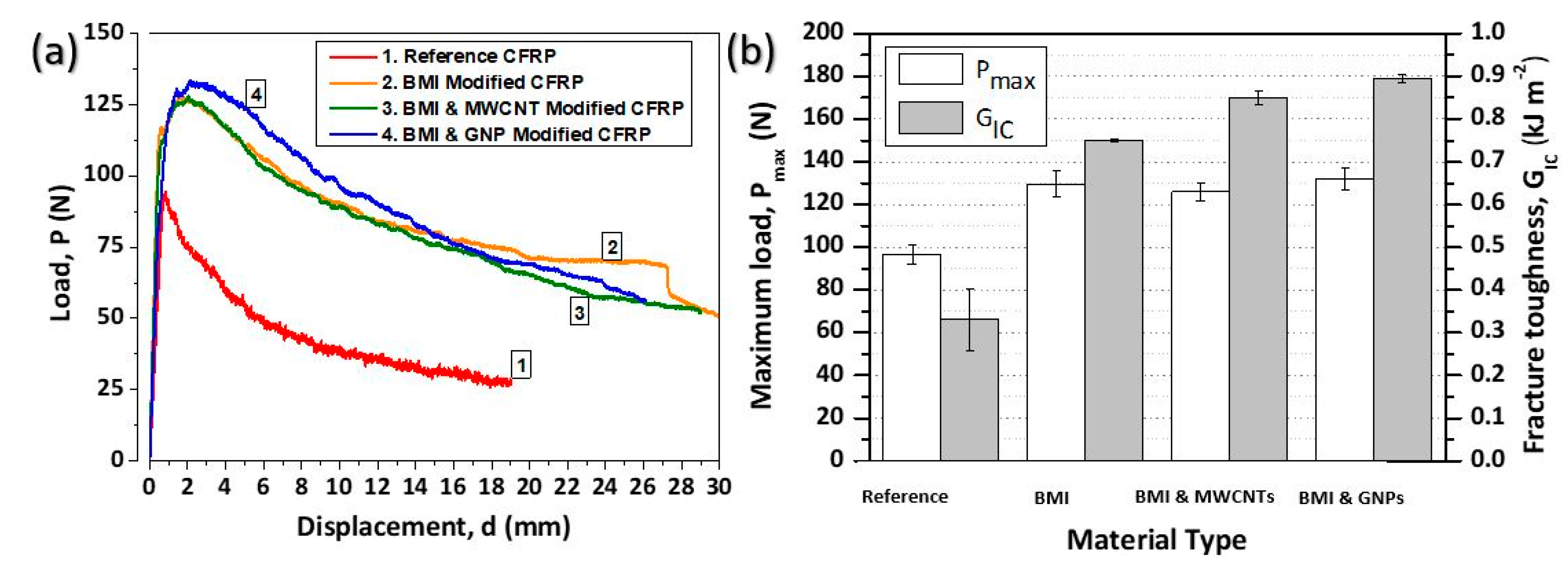
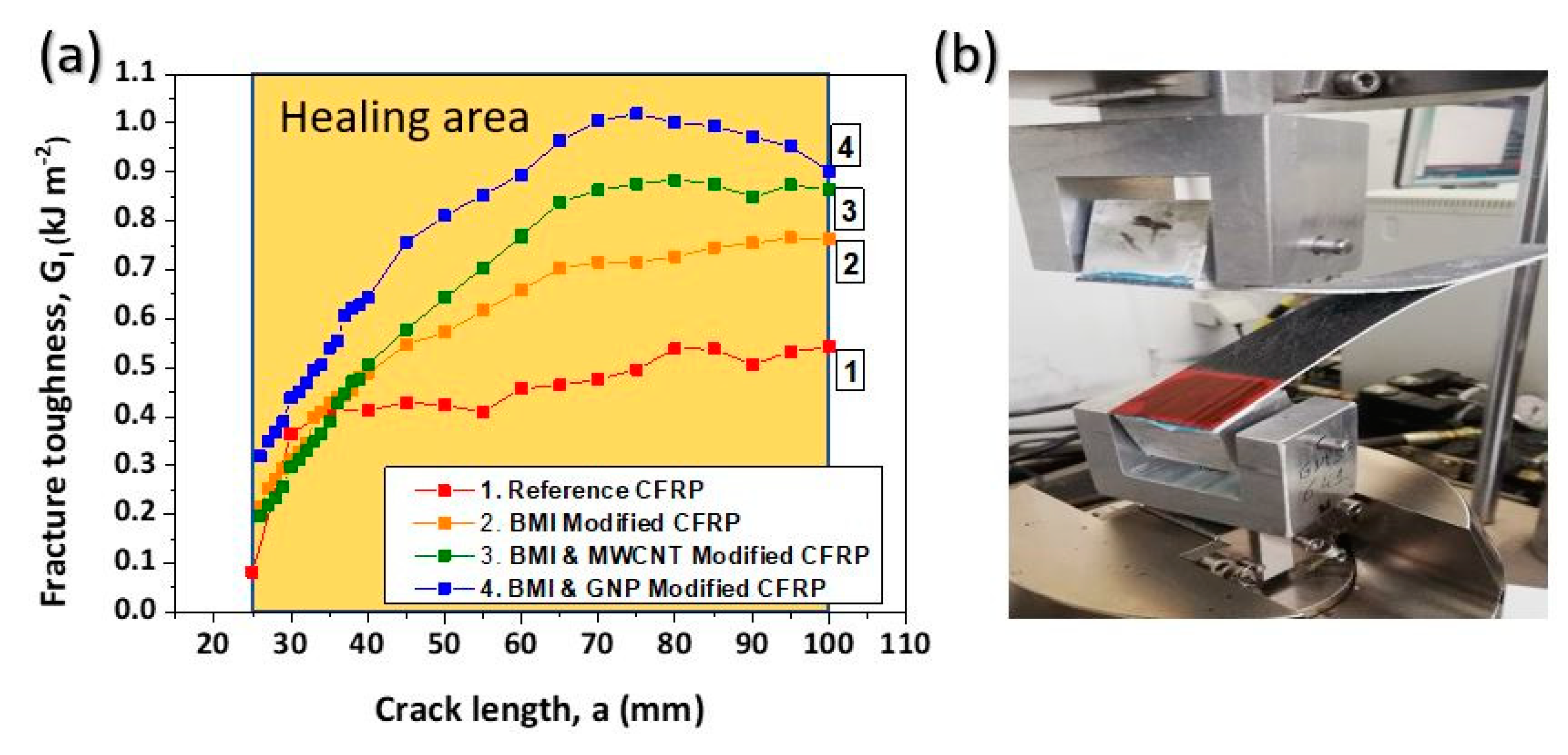
According to the C-scan inspections conducted, the manufactured plates (both reference and modified ones) showed absence of defects (porosity and/or delamination) due to the manufacturing process (see Figure 1c). In addition, representative OM images for reference and modified CFRPs, taken from the mid-thickness area of the samples (selected area, in which the crack propagates during Mode I testing), are provided. According to these images, the local darkening of the epoxy resin is prominent due to the presence of the SHA (Figure 4b) in modified samples, unlike reference ones (Figure 4a), after the autoclaving process.

3.3. Mode I Testing

The quasi-static interlaminar fracture toughness tests were performed according to the specifications described in Section 2.4. It is reasonable that the incorporation of the SHA into the composites structure in different forms (i.e., pure BMI, BMI modified with MWCNTs and BMI modified with GNPs) affects the Mode I fracture toughness of the laminates. The main objective of this experimental campaign at this point was (a) to investigate the most effective SHA system providing the best toughening performance and (b) to evaluate the contribution of each nano-filler type (MWCNTs or GNPs) to the final Mode I fracture toughness properties of the CFRPs.
Representative load (P) versus displacement (d) curves are provided and illustrated in Figure 5a. For all material sets, the general behavior did not present any significant difference as the applied load was linearly increased; this was followed by a deviation from the linearity and ended with a load drop after crack propagation onset. According to the experimental results, it was shown that all modified CFRPs presented enhanced fracture toughness mechanical properties, if compared to the reference material. Thus, the incorporation of the SHA in various forms (pure or nanomodified) has the potential to toughen the final CFRP. An analogous behavior was also observed in [6,18]; as such, SHAs usually have the potential to enhance the toughening profile of CFRPs. Finally, it is also obvious that the apparent stiffness of composites did not present any considerable difference.
The bar chart diagram in Figure 5b compares the Mode I interlaminar fracture toughness properties (Pmax and GIC values) for all material sets (reference and modified ones). It was shown that samples containing BMI SHA and GNPs exhibited the best toughening performance. More precisely, CFRPs containing pure SHA (BMI material) presented 34.1% (from 96.7 ± 4.0 to 129.7 ± 6.3) and 127.3% (from 0.33 ± 0.06 to 0.75 ± 0.11) higher Pmax and GIC values, respectively. For samples containing BMI and MWCNTs, these values were increased by 30.2% (from 96.7 ± 4.0 to 125.9 ± 1.8) and 157.6% (from 0.33 ± 0.06 to 0.85 ± 0.07), respectively. On the other hand, samples containing BMI and GNPs exhibited an increase of 36.8% (from 96.7 ± 4.0 to 132.3 ± 5.1) in the Pmax value and a 169.7% (from 0.33 ± 0.06 to 0.89 ± 0.03) increase in the GIC value.
Figure 6a provides and compares the crack opening resistance curves (R-curves) for all material sets. As it is clearly shown, the capacity of the SHA itself and nanofillers at the amount of 1 wt% to enhance the Mode I fracture toughness is evident according to these curves. Reference composites exhibited a limited damage process zone (lower than 5 mm), while they reached a plateau just after a crack propagation length of 30 mm. On the contrary, all modified samples exhibited significant enhancement of damage process zone (at least 20 mm larger against reference CFRP), while they reached a plateau just after a crack propagation length of 60–70 mm. Finally, all material sets promoted relatively stable delamination crack growths, as Figure 6a suggests. Figure 6b provides a snapshot during Mode I testing of a modified DCB CFRP specimen.
The increase in Mode I fracture toughness properties for modified CFRPs is strongly attributed to the bridging phenomenon due to the presence of the SHA that occurred between the crack flanks (top and bottom) (see Figure 7b). The main mechanism behind this is the suppression of the crack tip opening stresses, which resulted in the reduction in the crack opening displacement at a given applied load, if compared with the reference CFRP material. Such SHAs have the ability to enhance the fracture toughness properties of the final composite structure according to relative literature [6,18]. In addition to this, the presence of the nano-filler (MWCNTs or GNPs) into the SHA at the amount of 1 wt% gave an additional increase in the fracture toughness properties of the modified CFRPs with GNPs to provide the best toughening performance. The incorporation of such nano-fillers has shown to enhance the fracture toughness properties of composite structures. In [13], Kostopoulos et al. achieved to significantly increase the Mode I and Mode II fracture toughness properties of CFRPs by modifying them with CNT-reinforced copolymer nylon microparticles. The same author, in Ref. [22], also achieved a significant increase in the load bearing ability, as well as the fracture energy, of CFRPs, by addition of CNTs to the epoxy matrix. GNPs also have the potential to enhance the fracture toughness properties of CFRPs, according to Ref. [23]. On the other hand, reference CFRPs showed a clear brittle behavior as carbon fibers remain almost intact after Mode I testing, as OM implies (see Figure 7a).

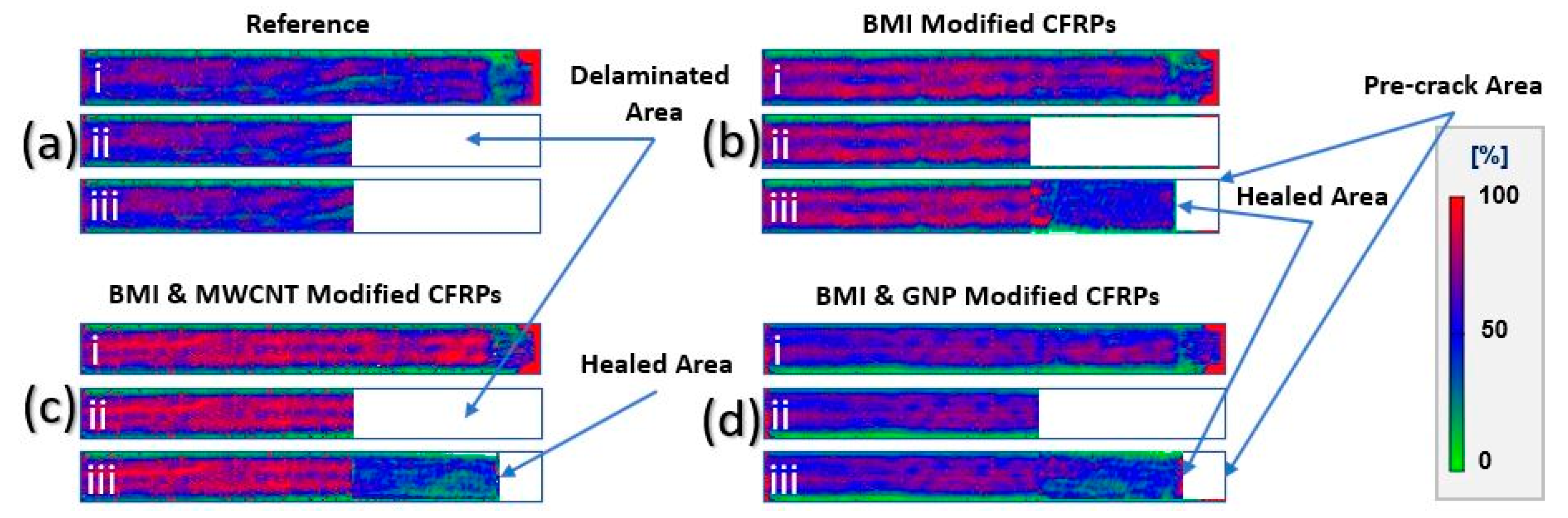
3.4. Repair of the Delaminated Area via Healing Treatment

To evaluate the H.E. of the proposed CFRPs (four specimen types), after the first testing cycle, all DCB specimens passed through the healing cycle consisting of uniform heating and compression, as Section 2.5 describes. Healing cycle parameters were selected taking into consideration previous publications in which the same SHA type was utilized [6,18].
Figure 8 presents C-scan inspection images for all material sets manufactured for the needs of the current study: prior Mode I testing (i), after fracture (ii) and after the healing process (iii). Figure 8a–d corresponds to reference, pure BMI, BMI and MWCNT and BMI and GNP modified CFRPs, respectively. The white area of the C-scan plots represents the delaminated area induced by the Mode I fracture toughness tests. According to these images, it was proved that all modified CFRPs exhibited healing functionality as based on C-scans and visual and macroscopical H.E. of 100% was achieved. On the contrary, reference specimens did not exhibit any measured healing functionality, as epoxy resin itself does not present any healing behavior. The deaminated area is clearly illustrated after fracture (image ii for all material sets), while the recovery of the delaminated area (healed one) is clearly illustrated (image iii for all modified samples apart from reference material). Finally, the white area in the front of the DCB specimens after the healing process represents the artificial crack area (pre-crack area) from which the healing properties are absent.
Figure 9 provides P versus d curves for the three modified CFRPs which exhibited healing functionality according to the C-scan plots of Figure 8, as reference CFRPs did not exhibit any measured healing behavior. According to this figure, none of the modified CFRPs exhibited a typical Mode I fracture toughness curve as, during the tests, the applied load was linearly increased up to fracture. From the three modified CFRPs, the specimen containing the pure SHA material (without nanofillers) seemed to have had the best healing performance, while, out of the two nanofiller-modified ones, the sample containing GNPs presented better recovery. Finally, for modified samples containing MWCNTs, the apparent stiffness was lower than the other two which presented a similar one.
According to the literature and previously published works by the authors [6,18], the utilized SHA type has the ability to heal the delaminations and partially to recover the Mode I fracture toughness properties when the DA reaction mechanism takes place after the healing process (i.e., through heating). Upon the DA reaction mechanism, SHA chains reconnect after the mechanical rupture caused by Mode I testing. In addition to this, the SHA material, when melted upon retro-DA reaction (i.e., above its Tm) during the healing process, flows easily between the crack flanks of the DCB specimen and equally distributes over the debonded crack flanks (see Figure 8). However, the poor recovery of the Mode I fracture toughness properties after the first fracture is mainly attributed to the infiltration of the SHA into the mid-thickness area during the curing process, as the SHA was incorporated in unreacted form through the SEP technique. Based on that, the SHA quantity into the mid-thickness area was insufficient to make the healed specimen able to bear higher loads under the applied extreme out-of-plane loading conditions during the Mode I testing. This behavior is also confirmed by OM images in Figure 7b, in which the absence of the SHA is prominent.

3.5. Effect of Self-Healing Agent and Nanofillers on In-Plane Mechanical Performance of CFRP Structure

The incorporation of the SHA containing or not nanofillers into CFRPs’ architecture is expected to have an impact on in-plane mechanical properties of the final composites. Based on that, 3PB tests were conducted according to the specifications provided in Section 2.6. Obviously, the tests were performed prior to the healing process.
The effect of the SHA containing or not nanofillers into the mid-thickness area on the in-plane mechanical properties of the CFRP structure is presented in Figure 10. The bar chart in Figure 10 provides the flexural modulus (EFlex) and flexural strength (σmax) values for all material sets. According to this figure, it can be seen that, by the incorporation of the SHA, for all cases, the EFlex was not affected, as it was only decreased by 1.2–2.7%. For all material sets, the EFlex value is into the margins of experimental errors and considered insignificant. On the other hand, the σmax value was decreased by almost 10% (from 9.5 to 10.5%) for all material sets against the reference CFRP. The slight σmax value decrease was expected, as the incorporated SHA during the curing process locally replaced part of the host epoxy resin matrix. An analogous behavior was also observed in Ref. [13].

4. Conclusions

In the current investigation, a new, healable CFRP composite structure was successfully manufactured by incorporating a DA-based SHA into the mid-thickness area. More precisely, three types of modified CFPRs have been manufactured by incorporating five surface-modified pre-preg tapes into the mid-plane area (locally, where appropriate), as well as a reference CFRP (without SHA). The modified CFRPs were as follows: one with pure SHA, one with SHA modified with 1 wt% MWCNTs and one with SHA modified with 1 wt% GNPs. After the manufacturing process, all CFRPs were tested under Mode I loading conditions and further assessed. Mode I experiments revealed that all modified CFRPs exhibited considerably enhanced Mode I fracture toughness properties with SHA- and GNP-modified ones exhibited the highest values, i.e., 36.8% increase in the Pmax value and 169.7% increase in the GIC value. R-curves confirmed the capacity of CFRP modification by SHA and nanofillers to enhance Mode I fracture toughness properties, as modified CFRPs exhibited larger damage process zone, if compared to the reference CFRPs. This behavior is mainly attributed to the extended bridging phenomenon that all modified samples exhibited due to the presence of the SHA in the mid-thickness area of the DCB specimens. After the first fracture, all material sets (reference and modified CFRPs) passed through the healing cycle in order for the healing capability to be assessed. According to C-scan inspections, all modified CFRPs were entirely healed (macroscopically and visually) apart from reference material (without healing functionality). After the healing process, the healed samples were tested under the same testing conditions in order for the potential recovery of the initial Mode I fracture toughness properties to be investigated. The repeating of tests showed a non-typical Mode I fracture toughness behavior, which is mainly attributed to the insufficient SHA quantity into the mid-thickness area of the specimen due to its infiltration during the curing process. The 3PB tests revealed no significant degradation effects due to the incorporation of the SHA. Finally, the absence of the SHA was confirmed by OM examinations of the fractured surface areas of the three modified samples.

Author Contributions

Conceptualization, methodology, investigation and validation, A.K., A.G. and V.K.; formal analysis and data curation, C.R. and A.K.; writing—original draft preparation and funding acquisition, A.K.; writing—review and editing, and project administration, A.K. and V.K.; supervision, V.K. Finally, the current investigation represents the diploma thesis of C.R. All authors have read and agreed to the published version of the manuscript.

Funding

This research is co-financed by Greece and the European Union (European Social Fund—ESF) through the Operational Program «Human Resources Development, Education and Lifelong Learning» in the context of the project “Reinforcement of Postdoctoral Researchers-2nd Cycle” (MIS-5033021), implemented by the State Scholarships Foundation (ΙKY).

Acknowledgments

The authors would like to thank Antonios Vavouliotis and the Adamant Composites LTD company for kindly assisting with the composites’ manufacturing procedure.

Conflicts of Interest

The authors declare no conflict of interest.

References

  1. O’Brien, Τ.K. Towards a damage tolerance philosophy for composite materials and structures. Compos. Mater. Test. Des. ASTM Spec. Tech. Publ. 1990, 1059, 7–33. [Google Scholar]
  2. Diesendruck, C.E.; Sottos, N.R.; Moore, J.S.; White, S.R. Biomimetic self-healing. Angew. Rev. 2015, 127, 10572–10593. [Google Scholar] [CrossRef]
  3. Van Gemert, G.M.L.; Peeters, J.W.; Sontjens, S.H.M.; Janssen, H.M.; Bosman, A.W. Self-healing supramolecular polymers in action. Macromol. Chem. Phys. 2012, 213, 234–242. [Google Scholar] [CrossRef]
  4. Williams, G.; Trask, R.; Bond, I. A self-healing carbon fibre reinforced polymer for aerospace applications. Compos. Part A Appl. Sci. Manuf. 2007, 38, 1525–1532. [Google Scholar] [CrossRef]
  5. Kostopoulos, V.; Kotrotsos, A.; Tsantzalis, S.; Tsokanas, P.; Loutas, T.; Bosman, A.W. Toughening and healing of continuous fibre reinforced composites by supramolecular polymers. Compos. Sci. Technol. 2016, 128, 84–93. [Google Scholar] [CrossRef]
  6. Kostopoulos, V.; Kotrotsos, A.; Tsantzalis, S.; Tsokanas, P.; Christopoulos, A.C.; Loutas, T. Toughening and healing of continuous fibre reinforced composites with bis-maleimide based pre-pregs. Smart Mater. Struct. 2016, 25, 84011. [Google Scholar] [CrossRef]
  7. Kostopoulos, V.; Kotrotsos, A.; Baltopoulos, A.; Tsantzalis, S.; Tsokanas, P.; Loutas, T.; Bosman, A.W. Mode II fracture toughening and healing of composites using supramolecular polymer interlayers. Express Polym. Lett. 2016, 10, 914–926. [Google Scholar] [CrossRef]
  8. Chen, Y.; Kushner, A.M.; Williams, G.A.; Guan, Z. Multiphase design of autonomic self-healing thermoplastic elastomers. Nat. Chem. 2012, 4, 467–472. [Google Scholar] [CrossRef] [PubMed]
  9. Gong, H.; Gao, Y.; Jiang, S.; Sun, F. Photocured Materials with Self-Healing Function through Ionic Interactions for Flexible Electronics. A.C.S. Appl. Mater. Interfaces 2018, 10, 26694–26704. [Google Scholar] [CrossRef] [PubMed]
  10. Li, C.-H.; Wang, C.; Keplinger, C.; Zuo, J.-L.; Jin, L.; Sun, Y.; Zheng, P.; Cao, Y.; Lissel, F.; Linder, C.; et al. A highly stretchable autonomous self-healing elastomer. Nat. Chem. 2016, 8, 618–624. [Google Scholar] [CrossRef] [PubMed]
  11. Wei, H.; Yang, Y.; Huang, X.; Zhu, Y.; Wang, H.; Huang, G.; Wu, J. Transparent, robust, water-resistant and high-barrier self-healing elastomers reinforced with dynamic supramolecular nanosheets with switchable interfacial connections. J. Mater. Chem. A 2020, 8, 9013–9020. [Google Scholar] [CrossRef]
  12. Kotrotsos, A.; Baltopoulos, A.; Tsantzalis, S.; Tsilimigkra, X.; Tsokanas, P.; Kostopoulos, V. Experimental investigation on self-healing efficiency of doped fiber reinforced plastics with PET micro-particles. UPB Sci. Bull. Series D Mech. Eng. 2016, 78, 67–76. [Google Scholar]
  13. Kostopoulos, V.; Kotrotsos, A.; Tsokanas, P.; Tsantzalis, S. Toughening and healing of composites by CNTs reinforced copolymer nylon micro-particles. Mater. Res. Express 2018, 5, 025305. [Google Scholar] [CrossRef]
  14. Kotrotsos, A.; Kostopoulos, V. Self-healing of structural composites containing common thermoplastics enabled or not by nanotechnology as healing agent. In Book Self-Healing Composite Materials, 1st ed.; Khan, A., Jawaid, M., Raveendran, S.N., Asiri, A.M.A., Eds.; Woodheal Publishing: Sawston, UK, 2020; Volume 18, pp. 327–374. [Google Scholar]
  15. Kennedy, J.P.; Castner, K.F. Thermally reversible polymer systems by cyclopentadienylation. I. A model for termination by cyclopentadienylation of olefin polymerization. J. Polym. Sci. Pol. Chem. 1979, 17, 2039–2054. [Google Scholar]
  16. Chen, X.; Dam, M.A.; Ono, K.; Mal, A.; Shen, H.; Nutt, S.R.; Sheran, K.; Wudl, F. A thermally remendable cross-linked polymeric material. Science 2002, 295, 1698–1702. [Google Scholar] [CrossRef] [PubMed]
  17. Kostopoulos, V.; Kotrotsos, A.; Sousanis, A.; Sotiriadis, G. Fatigue behaviour of open-hole carbon fibre/epoxy composites containing bis-maleimide based polymer blend interleaves as self-healing agent. Comp. Sci. Technol. 2018, 171, 86–93. [Google Scholar] [CrossRef]
  18. Kotrotsos, A.; Tsokanas, P.; Tsantzalis, S.; Kostopoulos, V. Healing of carbon fiber reinforced plastics by Diels–Alder based polymers: Effects of healing agent concentration and curing cycle. Appl. Polym. Sci. 2019, 136, 47478. [Google Scholar] [CrossRef]
  19. Kostopoulos, V.; Kotrotsos, A.; Geitona, A.; Tsantzalis, S. Low velocity impact response and post impact assessment of carbon fibre/epoxy composites modified with Diels-Alder based healing agent. A novel approach. Compos. Part A Appl. Sci. Manuf. 2021, 140, 106151. [Google Scholar] [CrossRef]
  20. AITM 1.0005. Airbus Industry Test Method, Carbon Fiber Reinforced Plastics, Determination of Interlaminar Fracture Toughness Energy, Mode I; Rescoll: Pessac, France, 1994. [Google Scholar]
  21. ASTM D7264M-07. Standard Test Method for Flexural Properties of Polymer Matrix Composite Materials; ASTM International: West Conshohocken, PA, USA, 2007. [Google Scholar]
  22. Karapappas, P.; Vavouliotis, A.; Tsotra, P.; Kostopoulos, V.; Paipetis, A. Enhanced Fracture Properties of Carbon Reinforced Composites by the Addition of Multi-Wall Carbon Nanotubes. J. Compos. Mater. 2009, 43, 977–985. [Google Scholar] [CrossRef]
  23. Kostagiannakopoulou, C.; Loutas, T.H.; Sotiriadis, G.; Kostopoulos, V. Effects of graphene geometrical characteristics to the interlaminar fracture toughness of CFRP laminates. Eng. Fract. Mech. 2021, 245, 107584. [Google Scholar] [CrossRef]
Figure 1. (a) Design of the reference and of the modified plates. (b) Illustration of a surface-modified pre-preg tape by electrospun SHA (BMI and TF). (c) C-scan inspection photographs of all material sets (reference and modified ones).
Jcs 05 00242 g001
Figure 2. Schematic representation of a modified double cantilever beam (DCB) test configuration: (a) side view; (b) top view. Dimensions in millimeter (mm).
Jcs 05 00242 g002
Figure 3. Schematic representation of the steps followed in the current investigation.
Jcs 05 00242 g003
Figure 4. Representative optical microscopy images from cross-section area of (a) reference and (b) SHA-modified CFRPs (representative image).
Jcs 05 00242 g004
Figure 5. (a) Typical load (P) versus displacement (d) curves for the reference and modified CFRPs with pure BMI, BMI and MWCNTs and BMI and GNPs. (b) Bar chart diagram containing the synopsis of Mode I testing results in terms of peak load (Pmax) and fracture toughness energy I (GIC) values.
Jcs 05 00242 g005
Figure 6. (a) Typical crack opening resistance curves (R-curves) under Mode I loading conditions for the reference and modified CFRPs with pure BMI, BMI and MWCNTs and BMI and GNPs. (b) Snapshot of a Mode I test specimen (double cantilever beam, DCB) during testing.
Jcs 05 00242 g006
Figure 7. Representative optical microscopy images from the fractured surface of (a) a reference and (b) a modified CFRP.
Jcs 05 00242 g007
Figure 8. C-scan inspection images of (a) a reference, (b) a BMI-modified CFRP, (c) a BMI- and MWCNT-modified CFRP and (d) a BMI- and GNP-modified CFRP, prior to Mode I testing (i), after fracture (ii) and after the activation of the healing process (iii).
Jcs 05 00242 g008
Figure 9. Typical load (P) versus displacement (d) curves for the reference and modified CFRPs with pure BMI, BMI and MWCNTs, and BMI and GNPs after the activation of the healing process.
Jcs 05 00242 g009
Figure 10. Bar chart diagram providing the flexural modulus (EFlex) and flexural strength (σmax) values for the reference and the modified CFRPs (with pure BMI, BMI and MWCNTs, and BMI and GNPs).
Jcs 05 00242 g010
Publisher’s Note: MDPI stays neutral with regard to jurisdictional claims in published maps and institutional affiliations.

