Article

Improving the Mechanical Properties of GlassFibre-Reinforced Laser-Sintered Parts Based on Degree of Crystallinity and Porosity Content Using a Warm Isostatic Pressing (WIP) Process

1
Department of Mechanical Engineering, Manufacturing Processes and Systems (MaPS), KU Leuven, Celestijnenlaan 300, 3001 Leuven, Belgium
2
Advanced Joining and Additive Manufacturing R&D Department, Korea Institute of Industrial Technology (KITECH), Siheung-si 113-58, Republic of Korea
3
Department of Materials Engineering, Structural Composites and Alloys, Integrity and Non-Destructive Testing (SCALINT), KU Leuven, Kasteelpark Arenberg 44, 3001 Leuven, Belgium
*
Author to whom correspondence should be addressed.
J. Manuf. Mater. Process. 2024, 8(2), 64; https://doi.org/10.3390/jmmp8020064
Submission received: 17 February 2024 / Revised: 8 March 2024 / Accepted: 21 March 2024 / Published: 25 March 2024
(This article belongs to the Special Issue Design, Processes and Materials for Additive Manufacturing)

Abstract

:
Additively manufactured fibre-reinforced polymers are gaining traction. After the development and optimisation of a novel fibre-deposition system in a laser sintering (LS) setup, polyamide 12 specimens were produced with and without glass fibres. In this study, the relation between the crystallinity, porosity, and mechanical properties of LS specimens with and without fibres is investigated. After testing as-built LS specimens, a detrimental effect of the fibres on the specimens’ performance was observed with a decrease in UTS of 6%. The degree of crystallinity remained the same; however, a porosity content of 2.6% was observed in specimens with fibres. These pores can have a negative influence on the bonding between the fibres and the matrix. To investigate the influence of the pores, warm isostatic pressing (WIP) was performed on LS specimens with and without fibres. The WIP process shows a positive influence on the specimens without fibres, resulting in an increase in UTS of 8.5%. The influence of the WIP process on specimens with fibres, however, is much less pronounced, with an increase in UTS of only 2%. Neither the crystallinity nor the porosity are the cause of the less-than-expected increase in UTS in LS specimens with fibres. A number of hypotheses and mitigation strategies are provided.

1. Introduction

Additive manufacturing (AM) technologies, such as fused filament fabrication (FFF) and laser sintering (LS), are promising techniques for the production of polymer-based components with a complex design. The increased geometric flexibility, reduced tooling costs, and short production cycles make these technologies able to compete with conventional production techniques when highly complex geometries or mass-customisation of parts are required [1,2]. AM technologies are mostly based on single-material printing, leading to mediocre mechanical properties, particularly in the case of polymers [1]. Coupled with a restricted selection of available materials, a broader industrial application of polymer AM parts, as well as optimisation of their mechanical properties, is significantly impeded. This contributed to the development of additively manufactured composite materials, for which a demand is rising in different industries, such as the automotive, aerospace, and biomedical industries [3].
For different polymer AM technologies, recent advancements have primarily targeted fibre-reinforced polymers. Nevertheless, numerous issues and challenges remain unresolved, demanding resolution before the widespread adoption of AM polymer composites in industry can be realised. The opportunity to fabricate intricately designed AM components with optimised strength and stiffness-to-weight ratios presents numerous innovative research prospects and engineering applications. Current research initiatives for AM composites have focussed on FFF, laminated object modelling (LOM), and stereolithography (SLA) [3,4,5,6,7]. Nano- and micro-scale particles and fibres, made from materials such as metals, aramids, ceramics, and, mostly, glass, are currently under investigation to enhance the mechanical properties of AM polymer parts with promising results [8]. However, void formation, poor adhesion of the fibres to the matrix, successful implementation of the fibres during conventional AM processes, and an inability to control the fibre orientation are some of the reported issues in the literature [3].
Laser sintering (LS) is another AM technique which is often used to produce polymers and is regarded as the preferred polymer AM technology for producing structural components. This preference is attributed to its relatively low anisotropy in comparison to FFF and other extrusion technologies, superior surface quality, and final part properties akin to those achieved through conventional manufacturing techniques, thereby resulting in durable and robust components [9,10]. LS parts are extensively used across various industries, with 95% of these components manufactured from polyamide 12 (PA12), as the polymer proves itself to be well suited to the LS process [5,11]. Hence, the majority of research endeavours and industrial applications focussing on LS polymer composites utilise a PA12 matrix, often incorporating glass or carbon fillers and fibres [5]. In prior research, conducted by the authors, the mechanical and fatigue performance of LS parts produced from commercially available glass-bead-filled PA12 (GF-PA12) was examined [12]. The study reported an increase in the stiffness of the LS components; however, this enhancement was achieved at the cost of reduced tensile strength and strain at fracture. Moreover, a significant adverse impact of the glass beads on the fatigue performance was observed. An assumption was made that the glass beads detach from the polymer matrix under significant or repeated deformation. This detachment renders the glass beads incapable of bearing any load whilst at the same time introducing stress concentrations, thereby resulting in an adverse effect on the fatigue characteristics. In addition to glass beads, various nano- and micro-scale fillers and fibres have also been explored for LS applications. These include carbon nano tubes (CNT), carbon black, carbon nanofibers, and nano silica, among others. These explorations have led to the development of several commercially available composite powders [13].
The efforts mentioned above aimed to introduce reinforcements into the LS process by uniformly blending conventional LS powders with additives. This approach is preferred because isotropic systems can offer the benefits of a fibre-reinforced material without the complications of anisotropic shrinkage and mechanical properties [8,14]. In order to effectively mix additives with the polymer powders, the fillers or fibres should ideally have roughly the same size as the powder particles, which typically average around 56 µm for PA12 powder. This similarity in size facilitates smooth layer deposition by the recoating roller onto the powder bed. Too large particles and fibres can cause defects in the deposited powder layer, too-small particles and fibres exhibit poor bulk flow at elevated temperatures which could be linked to higher interparticle friction [14]. Consequently, the examined fillers and fibres serve as less effective reinforcements due to their size. They fail to achieve the critical length necessary for complete stress transfer from the fibre to the matrix, up to its ultimate tensile strength [14,15,16]. The produced LS components exhibit some enhancement in elastic modulus, occasionally also in strength. However, substantial increases in strength are frequently absent due to the high internal porosity present throughout the part, exacerbated in regions with higher fibre content, and due to inadequate dispersion of the fibres and fillers in the powder feedstock [13].
In order to facilitate the integration of fibres exceeding both the length of the powder particles and the critical fibre length without disrupting the conventional LS process, powder and fibre deposition need to be decoupled. To that end, a novel fibre-deposition system was developed [17]. The present configuration of the system enables the successful production of LS specimens containing up to two vol% (5 wt%) glass fibres, measuring 3 mm in length and 14 µm in diameter. The aspect ratio of these long, chopped fibres surpasses that of previously examined fillers and fibres, potentially leading to a stronger composite material. Nonetheless, processing long, chopped fibres poses greater challenges; hence, the necessity for developing the fibre-deposition system. However, preliminary testing for which specimens with fibres were compared to specimens without fibres produced during the same LS build job, revealed no notable positive influence from the fibres on the mechanical properties. To comprehend this lack of a positive effect, the present study investigates the relationship between crystallinity, porosity content, and mechanical properties to gain insight into the behaviour of glass fibres within the PA12 matrix material. Mechanical properties were assessed through uniaxial tensile testing. The methodologies and findings, outlined in this paper, serve as a foundation for subsequent research endeavours concerning fibre-reinforced laser sintering of polymers, which has the potential to significantly improve part performance at limited additional cost.
Porosity can significantly affect the mechanical properties of LS-produced specimens, both with and without fibres. This influence is particularly pronounced in specimens with fibres, as porosity can compromise the bonding between the fibre and the matrix material [1,7,18,19]. It is common for LS parts to exhibit residual porosity ranging from around 2 to 3% [1,20]. To investigate the impact of porosity content on the LS specimens, the warm isostatic pressing (WIP) process was conducted. This method is well known for its ability to substantially reduce porosity content and enhance mechanical properties, primarily through an increase in the degree of crystallinity [1,2,3,9]. The effectiveness of the WIP process is investigated for both LS-produced specimens with and without fibres. However, for specimens containing fibres, the WIP process was primarily conducted to close porosity around the fibres. This approach aimed to enhance the bonding between the fibres and the matrix, thereby possibly improving the mechanical properties of LS-produced specimens with fibres.

2. Materials and Methods

2.1. Materials

Polyamide 12 (PA12) powder (PA 2200, EOS, d50 = 56 µm) was used as base material to produce specimens with the LS process. Continuous glass fibre strands (TUFRov type 4588, Nippon Electric Glass) were chopped in-house into fibres with an average length of 3 mm and diameter of 14 µm with an innovative fibre chopper (Vander Mast). The chopped glass fibres are used in combination with PA12 to produce reinforced specimens with the LS process. The continuous glass fibre strands are treated by the manufacturer with a silane sizing compatible with polyamide. Virgin PA12 powder was used to produce regular and reinforced test specimens.

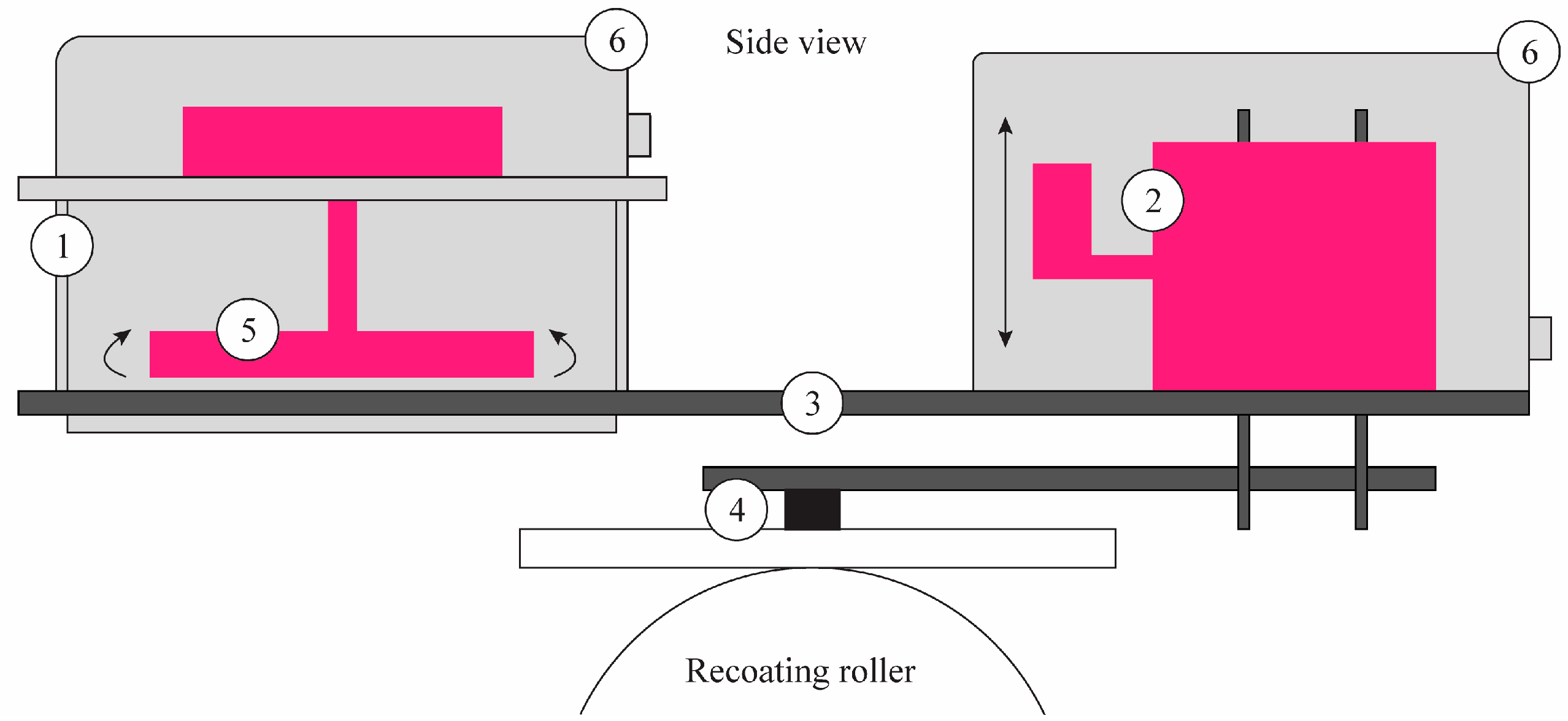
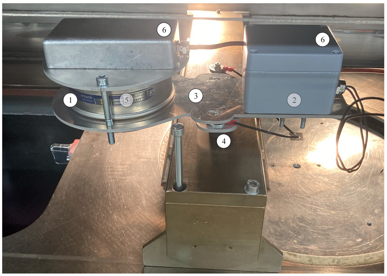
2.2. Laser Sintering

A commercial LS machine (DTM Sinterstation 2000), equipped with a CO2-laser and an in-house developed fibre-deposition system, was used to produce test specimens. During the LS process, cross-sections of the desired part are scanned by the laser on consecutive layers of preheated powder, spread on the build platform. These powder layers are paved on top of each other and the laser selectively consolidates the powder particles whilst unscanned and unsintered powder remains in place to support the produced part [21,22]. Specimens were built in the x-direction, parallel to the build platform and along the direction of the movement of the recoating roller. An inert nitrogen atmosphere is sustained during the LS build jobs. The geometry of the test specimens is shown in Figure 1 and is based on a type iv test specimen as per ASTM D638 but scaled down to facilitate printing with limited powder use. Previous work has shown no significant difference in mechanical behaviour between the regular type iv sample design and the design, as shown in Figure 1 [21].
Regular PA12 powder, without the addition of glass fibres, was used to produce specimens for a laser sintering parameter optimisation. The parameter optimisation was performed to maximise the density of the produced specimens and the analysis was performed based on Archimedes density (Acculab atilon ATL-244-1) measurements. Demineralised water was used to submerge the specimens. Upon immersion, some air bubbles were formed on the surface of the specimens which were removed manually. During the parameter optimisation, laser power (P) and scanning speed (v) were varied, whereas layer thickness (l) and scan spacing (s) were kept constant. The energy density (ED) was calculated for each LS-produced cuboid sample [10,23]:
  E D = P l × ,
In addition, the relative density was calculated by dividing the density measured by Archimedes, with the density of bulk PA12. The ED was compared to the relative density of the produced cuboid samples and based on the ED with the highest relative density, the LS processing parameters were chosen. An optimised set of LS parameters was selected (Table 1) and used to produce test specimens with and without fibres.
As mentioned above, the LS machine employed to produce the test samples is equipped with an in-house developed, novel fibre-deposition system. Figure 2 shows a schematic representation of the novel fibre-deposition system with its most important components:
  • Test sieve;
  • Vibrating system;
  • Support structure;
  • Connection and grounding;
  • Mixer;
  • Protective covers.
With the novel fibre-deposition system, longer, discontinuous fibres, different to those currently reported in the literature, can be injected onto the powder bed. As a result, facilitating the production of a polymer composite via LS with fibre lengths surpassing the critical fibre length for effective stress transfer from the matrix to the fibres. In addition, by injecting the fibres from the top onto the powder bed, it is assumed that a more random fibre orientation can be reached in-plane and some fibres might stick out-of-plane. Thereby, increasing the opportunity for intra-layer reinforcement of the polymer composite produced by LS. The working mechanism of the fibre-deposition system also allows deposition of diverse particles and fibres from various materials and with different geometries and lengths.
As mentioned, for this work, chopped glass fibres with a length of 3 mm are deposited during the LS process. To allow the deposition of these glass fibres, a test sieve with a mesh size of 3.35 mm is used. The fibre-deposition system can inject fibres onto the powder bed every two layers during the conventional LS process as the setup is mounted on top of the recoating roller of the LS machine (as can be seen in Figure 2 and Figure 3). During the LS process, the recoating roller travels from one side of the machine to the other to deposit a layer of powder onto the build platform. Two feed buckets are available on each side of the build platform to provide the roller with powder. Fibres are injected onto the powder bed just after the deposition of a new powder layer to limit the influence of the fibres on the smooth powder layer. Afterwards, the cross-section of the desired part is scanned. The recoating roller travels back to the other side of the machine, spreading a new layer of powder onto the powder bed without injection of fibres. Afterwards, again the cross-section of the desired part is scanned. These steps are continuously repeated throughout the LS build job. Glass fibres are injected onto the powder bed from the top.
Extensive optimisation was performed on the fibre-deposition system in order to reach a stable LS process with a sufficient number of deposited fibres (2 vol%, 5 wt%). Fibres are deposited on one half (bottom) of the build platform to allow the production of LS specimens with and without fibres in one build job. This allows us to reach a profound understanding of the influence of fibres on the produced LS specimens as the matrix material of the specimens is produced during the same LS build job, under the same conditions.
Also, for the fibre-deposition system, a parameter optimisation was performed based on the stability of the LS process and visual inspection of the produced specimens. The specimens were visually checked for delamination caused by the fibres. In the process, the delamination of the specimens tends to happen due to a combination of a high number of fibres injected and the force conducted onto the scanned layers with fibres by the recoating roller. A roller speed of 120 mm/s was chosen accompanied by a time delay of 4.2 s to travel over the feed bucket and a deposition time of 5 s set for the controlling system of the fibre-deposition system.

2.3. Post-Processing of Specimens

The WIP process was performed using a WIP machine consisting of a cylindrical chamber with a volume of 4400 cm3 and upper limits for temperature and pressure of 350 °C and 100 bar, respectively. The LS-produced specimens were vacuum-packaged at room temperature using a polyimide film and sealant tape [9]. Afterwards, the vacuum-packaged specimens were placed inside the chamber. Based on previous research by Park et al. [9], the temperature during the WIP process was increased to 180 °C, after which a nitrogen gas at pressure of 90 bar was applied for one hour. The specimens were cooled in the chamber after the WIP process was finished.

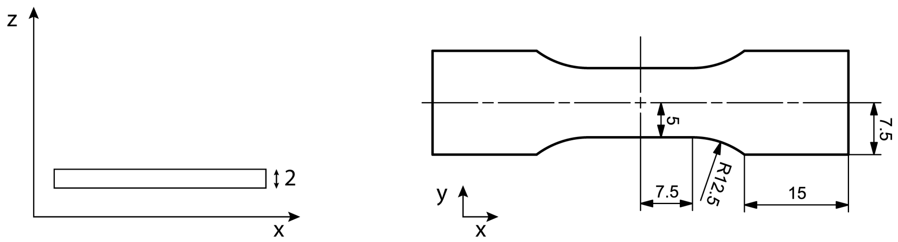
2.4. Analysis and Mechanical Characterisation

Differential scanning calorimetry (DSC) measurements were used to investigate the degree of crystallinity and its effect on the resulting mechanical properties. The higher the degree of crystallinity in the produced specimens, the stiffer and stronger they were, but also the more brittle the polymer material tends to be [24]. Material for the DSC measurements was taken from the entrapment of the specimens used for tensile testing. From each specimen, 8.25 ± 0.18 mg of material was manually sliced off with a sharp razor blade. Two temperature scans were performed on the material samples going from 20 °C to 240 °C and back, at a heating and cooling rate of 10 °C/min. The measurements were performed on a Q2000 DSC (TA Instruments) machine.
A 230 kV/300 W TESCAN UniTOM XL CT system (TESCAN XRE, Ghent, Belgium) was used for XCT imaging at the KU Leuven XCT Core Facility. The X-ray source is equipped with a tungsten reflection target. A voltage of 100 kV and a current of 150 µA was used and 2400 projections were generated. Each projection is an average of three radiographs acquired at each given rotation angle, ensuring a strong signal-to-noise ratio. To remove the low energy photons from the X-ray spectrum, a 0.1 mm thick brass filter was installed. By applying a magnification of 18.75 × a voxel edge size of 8 µm was obtained.
An Instron 3367 quasi-static machine, equipped with a 5 kN load cell and an Instron AVE2 video-extensometer, was used for tensile testing of the produced LS specimens. The tests were conducted at a displacement rate of 5 mm/min. Three specimens for each condition were tested, with the conditions being:
  • LS without fibres, as-built.
  • LS with glass fibres, as-built.
  • LS without fibres, post-processed with the WIP process.
  • LS with glass fibres, post-processed with the WIP process.
The width and thickness of the test section of each test specimen was measured by a set of Vernier callipers (Mitutoyo) and used as input for the Instron software to calculate the dimensions of the cross-sections and subsequently the correct stress values.
Observations and porosity analysis of the fracture surfaces after tensile testing were performed using scanning electron microscopy (SEM) (FEI XL30-FEG). The fracture surfaces of two specimens were analysed for each condition.

3. Results and Discussion

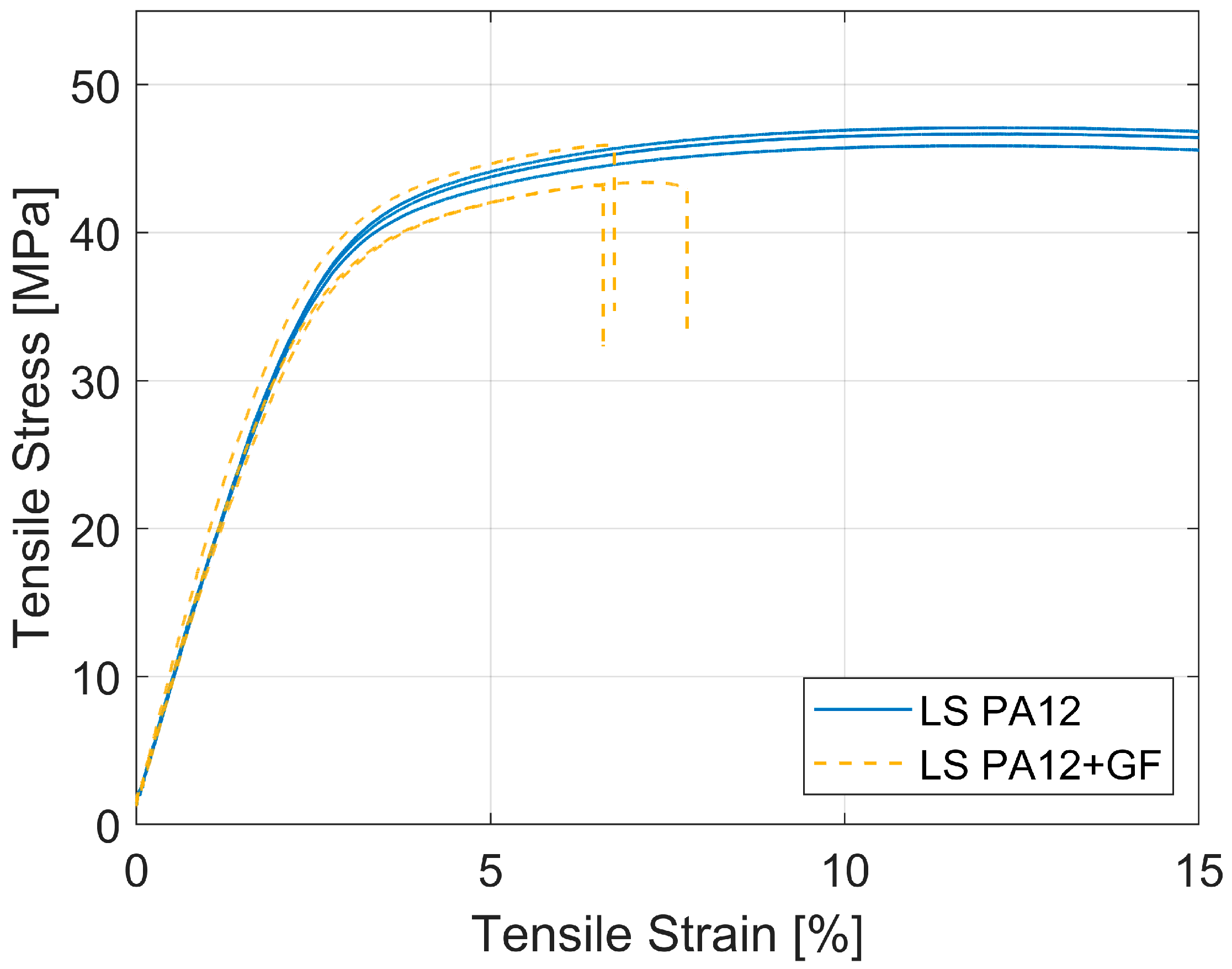
3.1. Mechanical Properties of Specimens without Post-Processing

After the extensive testing and optimisation of the LS process with the in-house developed fibre-deposition system, tensile specimens were produced and tested. Three specimens with glass fibres and three specimens without glass fibres were tested as-built (without post-processing) to compare and investigate the influence of the glass fibres on the mechanical properties. As mentioned above, a fibre volume fraction of approximately two vol% (5 wt%) is expected in the specimens. Figure 4 shows the stress–strain data and Table 2 summarizes the averaged mechanical properties of the tested as-built LS specimens with and without fibres. The mechanical properties are analysed and calculated following ISO 527-1:2019(en) for plastics with UTS being ‘stress at break’ (σb), strain being ‘strain at break’ (εb), and strength being ‘stress at 0.5% strain’ (σx) [25].
All specimens, for which the results are shown in Figure 4 and Table 2, are built in the same LS build job with the same PA12 powder as base material. Therefore, the focus is on how the addition of glass fibres influences the material and mechanical properties of the produced specimens. After analysis of the results, the following phenomena are noted:
  • A small decrease (6%) in ultimate tensile strength (UTS) is observed for LS specimens with glass fibres, compared to LS specimens without glass fibres.
  • When glass fibres are added to the LS specimens, a minor increase in modulus of elasticity (E-modulus) and a decrease in fracture strain are observed. This shows that, when glass fibres are added, the specimens tend to become more brittle.
Against expectations, no significant increase in tensile strength was noted after the addition of chopped glass fibres to the produced specimens. It could be assumed that the fibre volume fraction of two vol% is rather low and, therefore, no positive effect of the fibres on the tensile strength of the specimens can be observed. However, they do become significantly more brittle. Previous research also shows that a fibre weight fraction of 5 wt% fibres has a significant positive influence on the mechanical properties of produced specimens, both for carbon fibres [26,27] and for glass fibres [28,29]. In addition, it should be noted that the alignment of the fibres has a significant influence on the mechanical properties of composites [30,31]. The orientation of LS-produced specimens with fibres is mostly random, as it is not possible to align the fibres with the current fibre-deposition system. Randomly oriented fibres are known to have a lower influence on the mechanical properties of composites when compared with aligned fibres. Nevertheless, a random fibre orientation in the specimens should still show at least some improvement in tensile strength compared to a negative influence.
To understand what is causing the negative influence of the glass fibres on the UTS and marginal influence on the E-modulus, the specimens were further investigated by means of DSC and XCT imaging as the degree of crystallinity and porosity can have a considerable influence on final mechanical properties. Figure 5 shows the region of interest (around the melting point) of the DSC data for the as-built PA12 specimens with and without fibres. More heat flow is needed when the melt temperature of the specimens is reached as melting is an endothermic reaction. Therefore, the DSC curves in Figure 5 show negative peaks in the heat flow curves [21]. The additional small negative peak after the first peak is often observed for LS specimens as fully molten particles and unmolten particle cores surrounded by spherulites are present in the microstructure of LS parts [21]. The melting temperature of these unmolten particle cores equals the melting temperature of the PA12 powder, causing an additional small peak. A deeper peak can be observed for the specimens with glass fibres, suggesting the presence more unmolten particles in these specimens. It can be assumed that the glass fibres absorb some of the laser energy resulting in unmolten PA12 particles. By calculating the area of the melting peaks, the heat of melting in J/g can be found and with Equation (2) the percentage of crystallinity (C%) can be calculated [21,32]. Gogolewski et al. reported a heat of melting of 209.3 J/g for a 100% crystalline PA12 specimen [33].
C % = H e a t   o f   m e l t i n g   ( s a m p l e ) H e a t   o f   m e l t i n g   ( 100 %   c r y s t a l l i n e   s p e c i m e n ) ,
To bring the influence of the deposited glass fibres into account, Equation (2) must be modified. Glass has a much lower specific heat compared to PA12 and has to be taken into account to estimate the real crystallinity of the produced specimen with glass fibres [34]:
X C = Δ H C Δ H f × ( 1 m g ) ,
With mg being the mass fraction of the glass in the composite which is in this case approximately five wt% (2 vol%) and was identified via XCT scanning. ΔHC and ΔHf are the same values as used in Equation (2), ‘heat of melting (sample)’ and ‘heat of melting (100% crystalline specimen)’, respectively.
Equation (2) yields a percentage of crystallinity of 42% for the LS PA12 specimens without fibres. Equation (3) yields a percentage of crystallinity of 43% for the LS PA12 specimen with fibres. The degree of crystallinity for both materials remains almost the same, a very slight increase of 1% crystallinity is noted when fibres are added to the material. It can be assumed that, because glass fibres have a high thermal conductivity, more heat of the LS process is conducted to the PA12 material resulting in higher crystallinity [35]. However, an increase of 1% in crystallinity is assumed to have no significant influence when specimens from both conditions (conditions 1 and 2) are compared. Therefore, it can be reasoned that a difference in crystallinity is not the cause of the lower-than-expected mechanical strength and Young’s modulus of the glass-fibre-reinforced specimens.
Also, porosity can have a significant influence on mechanical properties of produced specimens [1,36]. A residual porosity of around 2–3% is common in LS parts [1,20]. However, when glass fibres are added to the produced LS specimens, it can be assumed that due to this residual porosity, the fibres are not completely impregnated and insufficient bonding with the matrix material can occur, especially when pores are located at the matrix/fibre interface. To investigate the porosity content in the LS-produced specimens with fibres, XCT imaging was conducted. Results from the XCT imaging are shown in Figure 6 and Figure 7. After analysis, a porosity content of 2.6% was found, which is, as mentioned before, expected for the LS process. Based on Figure 6 and Figure 7, no clear correlation between the fibres and the pores can be observed. However, after further analysis of the XCT data, as can be seen in Figure 8, some correlation can be observed regarding the residual fibre bundles and pores. Therefore, the influence of the porosity was investigated by applying the WIP process to the produced specimens to reduce porosity [9]. The WIP process was also performed in an effort to increase impregnation of the fibres as pressure is applied on the specimens at elevated temperatures. As a result, the WIP process could potentially increase the bonding between fibre and matrix and improve the mechanical properties of the specimens with fibres.

3.2. Effect of the WIP Process on LS Specimens with Glass Fibres

The WIP process was conducted on the LS specimens to mitigate porosity within the matrix, enhance fibre impregnation, and potentially increase the interfacial bonding with the matrix. Consequently, aiming for an improvement in the mechanical properties of LS-produced specimens with fibres. Figure 9 shows the tensile curves of the specimens of all four conditions tested in this study, with the results of the specimens post-processed with the WIP process highlighted (conditions 3 and 4). Table 3 summarizes the averaged mechanical properties of the tested as-built and post-processed LS specimens with and without glass fibres [25].
When only the specimens without fibres are compared before and after the WIP process (conditions 1 and 3), a significant influence of the WIP process on the mechanical properties can be observed. The UTS of the specimens increased by approximately 8,5% which is in line with earlier reported results by Park et al. [9]. Also, the E-modulus increased significantly by approximately 12% and the fracture strain decreased by approximately 43%.
When the specimens with fibres are compared before and after the WIP process (conditions 2 and 4), the influence of the WIP process on the mechanical properties is less significant. The UTS of the specimens increased with approximately 2%, which is less pronounced compared to conditions 1 and 3. However, the E-modulus increased by approximately 8% and the fracture strain decreased by approximately 28.5%, which is more in-line with the results obtained from the specimens without fibres.
When all specimens are compared for all four conditions, the following phenomena can be noted:
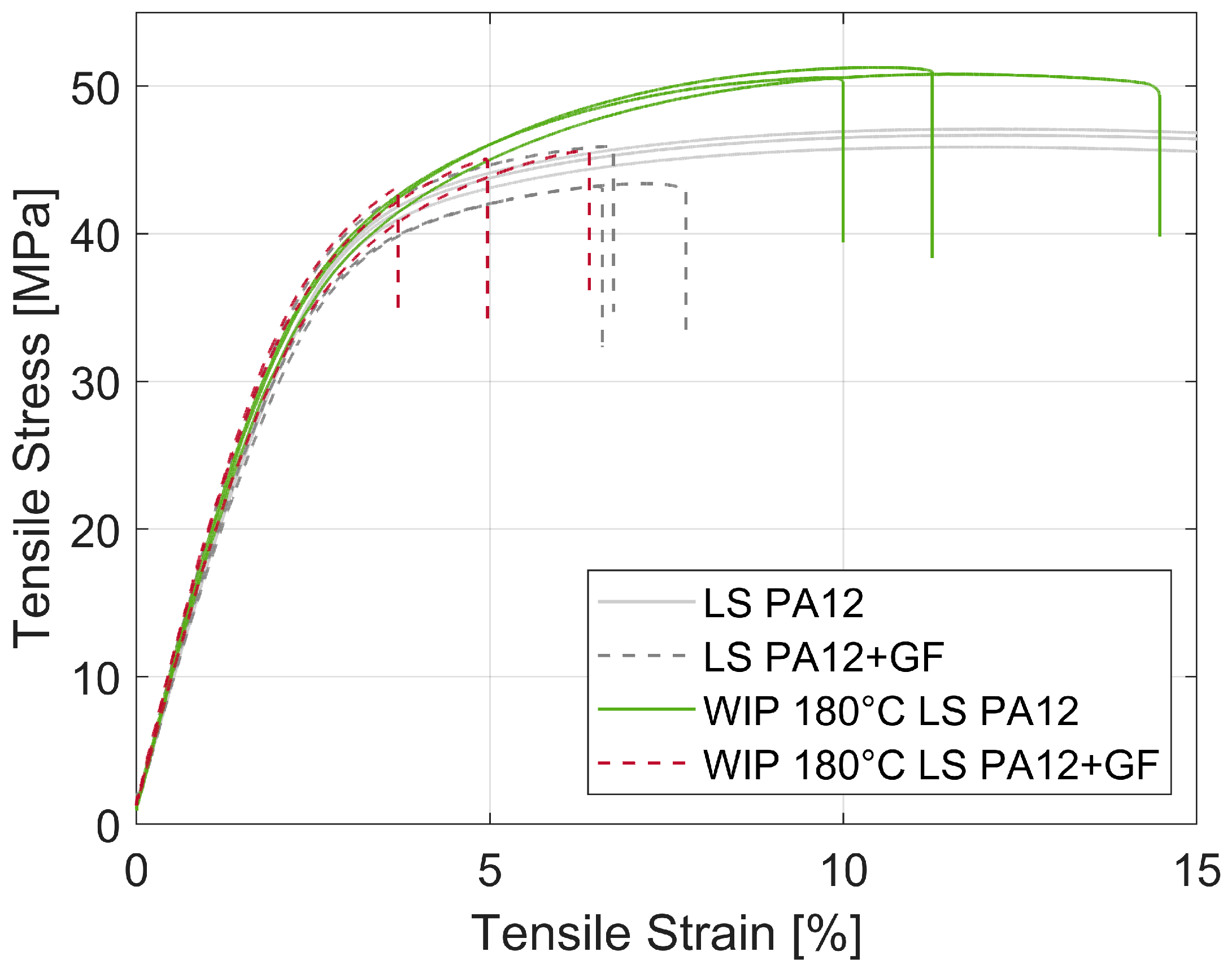
  • After the WIP process, the UTS of the LS-produced specimens with fibres remains lower compared to specimens without fibres. Before the WIP process, a decrease of 6% in UTS was noted for specimens with fibres compared to specimens without fibres. After the WIP process, when WIP-produced specimens with and without fibres are compared (conditions 3 and 4), an even higher discrepancy of 12% in UTS can be noted. This is related to the significant influence of the WIP process on specimens without fibres compared to the limited influence on specimens with fibres. Given that the WIP process only influences the matrix material, the marginal increase observed for the UTS of specimens with fibre can be attributed to the closure of pores within the matrix.
  • For specimens both with and without fibres, an increase in E-modulus and a decrease in the fracture strain are noted after the WIP process. The specimens with fibres and post processed with the WIP process have the highest E-modulus and lowest fracture strain. This shows that the addition of glass fibres but also the post processing with the WIP process results in more brittle parts. These results are in line with earlier reported results by Park et al. [9].
Figure 10 shows SEM images of the fracture surfaces after tensile testing of two as-built LS specimens with fibres (condition 2). Traces of pores, pull-out of glass fibres, and glass fibres sticking out of the surface can be observed. The holes left by pull-out of glass fibres are much smaller compared to the holes left by porosity in the parts. By the number of fibre pull-out and fibres sticking out of the fracture surface, it could be assumed that insufficient bonding and limited impregnation of the fibres with the matrix material are the driving factors behind the negative influence of the fibres on the mechanical properties of the LS-produced specimens.
Figure 11 show SEM images of the fracture surfaces after tensile testing of two LS specimens with fibres post-processed with the WIP process (condition 4). These images clearly show the influence of the WIP process as the fracture surfaces show a more brittle fracture and no porosity is visible which is also reported by Park et al. for PA12 specimens after the WIP process [9]. However, also after the WIP process, quite some fibre pull-out and glass fibres sticking out of the surfaces can be observed. A high pressure of 90 bar accompanied by an elevated temperature of 180 °C, just above the melting temperature of the PA12 material, was applied to the specimens but it can be assumed that no further impregnation of the fibres with matrix material occurred.
As mentioned before, also the degree of crystallinity has an influence on the mechanical properties of produced parts. Figure 12 shows the DSC data of the specimens of all four conditions tested in this study, with the results of the specimens post-processed with the WIP process highlighted in green and blue (conditions 3 and 4). Equation (2) yields a percentage of crystallinity of 47% for the LS PA12 specimens without fibres, post-processed with the WIP process. Equation (3) yields a percentage of crystallinity of 49% for the LS PA12 specimen with fibres and post-processed with the WIP process. Also, after the WIP process, the degree of crystallinity for both materials remains almost the same, a slight increase of 2% crystallinity is noted in the specimens with fibres compared to the specimens without fibres. However, if also the specimens without post-processing are considered (all conditions), an increase in percentage of crystallinity is noted of 12% for the specimens without fibres after the WIP process (conditions 1 and 3) and an increase of 14% for the specimens with fibres after the WIP process (conditions 2 and 4). Park et al. reported an increase in percentage of crystallinity of approximately 10% which comes close to the results reported in this study [9]. The observed increase in E-modulus, as well as decrease in strain at fracture, for specimens with fibres after the WIP process may partially be explained by the increase in crystallinity. For the post-processed specimens without fibres, no additional small peak is observed. However, for the post-processed specimens with fibres, the additional small peak is still present which shows that even after the WIP process some unmolten particles are still present in the material.
As both the specimens with and without glass fibres show an increase in crystallinity after the WIP process, the same influence of that increase should be noted on the mechanical properties of the specimens. However, a significant increase in the mechanical properties for specimens without fibres was noted after the WIP process compared to a limited change for the specimens with fibres. Thus, it can be assumed that the degree of crystallinity is not the driving factor for the limited influence of the glass fibres on the mechanical properties of the produced specimens.

4. Discussion

In this study, the relation between the crystallinity, porosity, and mechanical properties of laser-sintered PA12 specimens with and without chopped glass fibres, as-built and post-processed with the WIP process, was investigated. When only the addition of glass fibres to LS-produced specimens is considered, and a decrease in UTS of 6% is observed. Also, an increase in E-modulus and a decrease in fracture strain are observed, making the specimens with fibres more brittle. The decrease in UTS is against expectations as the applied fibres are longer than the critical length for glass fibres with PA12 and a sufficient number of fibres are present in the produced specimens. As there is no significant influence of the fibres on the crystallinity of the produced parts that could explain a decrease in UTS, the focus was shifted towards the porosity present in the part. XCT imaging revealed a 2.6% porosity content in the LS specimens with fibres which is expected for an LS material but could potentially have a detrimental effect on the bonding of the fibres with the matrix material. Therefore, the WIP process was applied to the specimens to reduce the porosity content and to increase the impregnation of the fibres with the matrix material. During the WIP process, pressure is applied on the specimens under elevated temperatures, above the melting temperature of the matrix material. Pressure is important for the successful production of a polymer composite material and is lacking during the LS process.
After the WIP process, the post-processed specimens were investigated in the same manner as the ‘untreated’ LS specimen. The WIP process had a significant influence on the LS PA12 specimens without fibres and increased the UTS by 8.5%. Also, the E-modulus was increased and a decrease in fracture strain was observed. However, this significant increase was not noted for the LS specimens with fibres. Only a minor increase in UTS of 2% was observed. When all specimens (from all four conditions) were compared, the ‘untreated’ LS specimens with glass fibres exhibit the lowest mechanical properties, followed by the LS specimens with fibres after the WIP process. The minimal impact of the WIP process on the LS specimens is assumed to be related to fact that the WIP process primarily affects the matrix material. The WIP process seems to have no influence on the interaction of the fibres with the matrix. The fibres tend to act as defects in the specimens with a detrimental effect on the mechanical properties. This study shows that both porosity and crystallinity are not the driving factors behind the negative influence of the glass fibres on the LS specimens.
Further assumptions about these driving factors can be made. A first assumption is that there is insufficient impregnation and bonding of the fibres with the matrix material in the specimens. During conventional manufacturing, e.g., injection moulding, high (shear) pressures are present ensuring proper bonding of the glass fibres with the matrix material. The sizing present on the surface of the glass fibre is activated by these pressures and is a driving factor for the proper bonding of the fibre with the polymer matrix [37]. An assumption could be made that the lack of pressure during the LS process limits the proper bonding of fibre and matrix. Another assumption is that the laser, active during the LS process, radiates the glass fibres directly and during this irradiation the sizing, needed for the proper bonding of the fibre and matrix, is ‘burned’ off or damaged, resulting in insufficient bonding. This could indeed limit the effect of the WIP process on the produced parts. A last assumption could be that the fibres are not well dispersed in the produced material; thus, insufficient impregnation of the fibres occurs in the LS specimens. During the production process of glass fibres, the fibres are bundled together, making dispersion of the fibres without pressure, stresses or matrix material with a low viscosity very hard [37]. If there is insufficient bonding/impregnation of the fibres in the matrix material, the fibres can act as defects in the polymer material which has a detrimental effect on the mechanical properties. As mentioned before, the alignment of the fibres in the part has a significant influence on the mechanical properties of composite materials. Currently, the chopped glass fibres are randomly injected onto the powder bed and a random fibre orientation is known to results in lower strength increases compared to when fibres are aligned along the direction of the stresses. Further research and optimisations are needed to fully understand the driving factors behind the influence of the glass fibres on LS-produced parts.

5. Conclusions

After the development of an innovative fibre-deposition system, PA12/glass fibre composite specimens were produced with the LS process. The glass fibres were chopped in house and have a length of 3 mm and a diameter of 14 µm. The developed fibre-deposition system enables the production of specimens both with and without fibres during the same build job, allowing a fair comparison between pure PA12 and composite glass fibre/PA12 samples. After initial tensile testing of LS-produced specimens with and without fibres, the presence of fibres was shown to have a negative influence on the UTS. A decrease of 6% in UTS was noticed between as-built specimens without fibres compared to as-built samples with fibres. Also, a minor increase in E-modulus and decrease in fracture strain was noticed. To understand this negative influence of the fibres on the mechanical properties of the LS specimens, the relation between crystallinity, porosity content, and mechanical properties was investigated. No significant difference in crystallinity between LS specimens with and without fibres was noted. However, a porosity content of 2.6% in specimens with fibres could result in an insufficient bonding of the glass fibres with the matrix material PA12. To investigate the influence of this porosity, the WIP process was used as post-processing technique, as it is known to decrease porosity and increases the mechanical properties of treated parts.
After the WIP process was performed on specimens with and without fibres, a clear positive influence was observed on LS specimens without fibres. An increase in UTS of 8.5% was noted and can be attributed to an increase in degree of crystallinity and a decrease in porosity content present in the specimens. However, this positive influence is not as pronounced for specimens with fibres. Only a 2% increase in UTS could be observed, which is assumed to be linked to an increase in the degree of crystallinity and decrease in porosity content in the parts. The fibres still have a negative influence on the LS-produced specimens after the WIP process. Assumptions can be made about the driving factors of this negative influence of the fibres including, but not limited to:
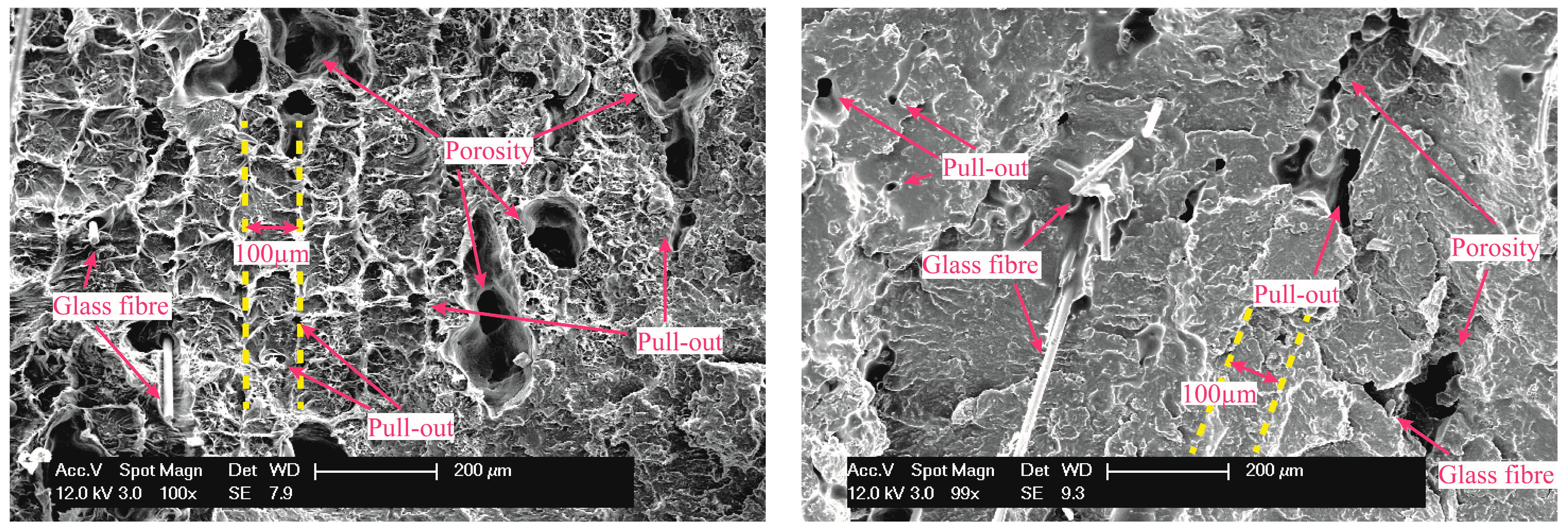
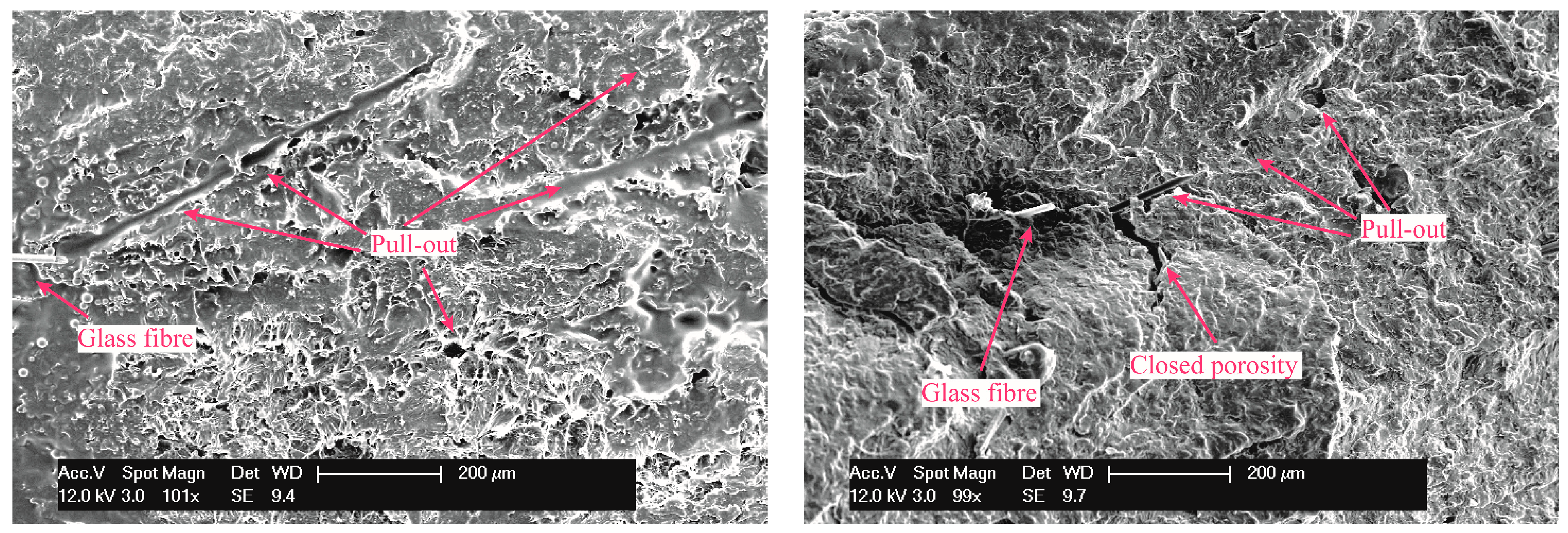
  • Insufficient impregnation of the fibres and insufficient bonding of the fibres with the matrix material;
  • In-process damaging (e.g., thermal degradation caused by the selective laser scanning) of the sizing, present on the glass fibres and necessary for ensuring sufficient bonding between fibre and matrix material;
  • Bundles of glass fibres present in the part acting as big defects and degrading the mechanical properties;
  • The random orientation of the chopped glass fibres contributes less to the mechanical properties of composites compared to an aligned fibre orientation.
Further profound investigations are needed to fully understand the driving factors behind the negative influence of glass fibres.

6. Outlook

To overcome the issues with insufficient impregnation and bonding of the fibres with the matrix material, a switch was made to carbon fibres as the sizing is less important for these fibres. Carbon fibres can have a positive influence on the mechanical properties of the produced specimen even without sizing. Recycled carbon fibres were used in this case as during the recycling process the sizing is removed [37]. Carbon fibres can also be injected onto the powder bed by the in-house developed fibre-deposition system. From preliminary SEM images, better bonding can be observed between the carbon fibres and the PA12 matrix material after the LS process. Figure 13 shows a SEM image of a fracture surface after tensile testing of an LS specimen with carbon fibres.

Author Contributions

H.D.C.: Methodology, Formal analysis, Investigation, Writing—Original Draft, Visualization. J.W.C.: Planning and designing all the WIP process, reviewing papers. J.S.: Formal analysis, Investigation, Writing—Review and Editing. S.M.: Methodology, Formal analysis, Writing—Review and Editing. B.V.H.: Methodology, Formal analysis, Writing—Review and Editing, Supervision. All authors have read and agreed to the published version of the manuscript.

Funding

This research received no external funding.

Data Availability Statement

Data are contained within the article.

Acknowledgments

This work was supported by the European Space Agency (ESA) as part of a co-funded PhD OSIP project AO_3-17001_SC_30750, and the research fund of KU Leuven through C3-project C3/20/083. We acknowledge the KU Leuven XCT Core Facility for the 3D image acquisition and quantitative post-processing tools (www.xct.kuleuven.be).

Conflicts of Interest

The authors declare no conflicts of interest.

References

  1. Abbott, C.S.; Sperry, M.; Crane, N.B. Relationships between porosity and mechanical properties of polyamide 12 parts produced using the laser sintering and multi-jet fusion powder bed fusion processes. J. Manuf. Process. 2021, 70, 55–66. [Google Scholar] [CrossRef]
  2. Zhang, S.; Tang, H.; Tang, D.; Liu, T.; Liao, W. Effect of fabrication process on the microstructure and mechanical performance of carbon fiber reinforced PEEK composites via selective laser sintering. Compos. Sci. Technol. 2024, 246, 110396. [Google Scholar] [CrossRef]
  3. Parandoush, P.; Lin, D. A review on additive manufacturing of polymer-fiber composites. Compos. Struct. 2017, 182, 36–53. [Google Scholar] [CrossRef]
  4. Alghamdi, S.S.; John, S.; Choudhury, N.R.; Dutta, N.K. Additive manufacturing of polymer materials: Progress, promise and challenges. Polymers 2021, 13, 753. [Google Scholar] [CrossRef] [PubMed]
  5. Lupone, F.; Padovano, E.; Casamento, F.; Badini, C. Process phenomena and material properties in selective laser sintering of polymers: A review. Materials 2022, 15, 183. [Google Scholar] [CrossRef] [PubMed]
  6. Regassa, Y.; Lemu, H.G.; Sirabizuh, B. Trends of using polymer composite materials in additive manufacturing. In IOP Conference Series: Materials Science and Engineering; IOP Publishing: Bristol, UK, 2019; Volume 659, p. 012021. [Google Scholar]
  7. Wang, X.; Jiang, M.; Zhou, Z.; Gou, J.; Hui, D. 3D printing of polymer matrix composites: A review and prospective. Compos. Part B Eng. 2017, 110, 442–458. [Google Scholar] [CrossRef]
  8. Goh, G.D.; Yap, Y.L.; Agarwala, S.; Yeong, W.Y. Recent Progress in Additive Manufacturing of Fiber Reinforced Polymer Composite. Adv. Mater. Technol. 2019, 4, 1800271. [Google Scholar] [CrossRef]
  9. Park, S.J.; Choi, J.W.; Park, S.J.; Son, Y.; Ahn, I.H. Improving properties of a part fabricated by polymer-based powder bed fusion using a warm isostatic press (WIP) process. Mater. Des. 2022, 224, 111417. [Google Scholar] [CrossRef]
  10. Kruth, J.P.; Levy, G.; Klocke, F.; Childs, T.H.C. Consolidation phenomena in laser and powder-bed based layered manufacturing. CIRP Ann.-Manuf. Technol. 2007, 56, 730–759. [Google Scholar] [CrossRef]
  11. Goodridge, R.D.; Tuck, C.J.; Hague, R.J.M. Laser sintering of polyamides and other polymers. Prog. Mater. Sci. 2012, 57, 229–267. [Google Scholar] [CrossRef]
  12. De Coninck, H.; Meyers, S.; Van Puyvelde, P.; Van Hooreweder, B. On the Difference in Mechanical Behavior of Glass Bead-Filled Polyamide 12 Specimens Produced by Laser Sintering and Injection Molding. 3D Print. Addit. Manuf. 2022, 1–21. [Google Scholar] [CrossRef]
  13. Kozior, T. Assessment of mechanical properties of pa 3200 gf polyamide models made by SLS. Czas. Tech. 2018, 11, 181–186. [Google Scholar] [CrossRef]
  14. Forderhase, P.; Mc Alea, K.; Booth, R. The development of an SLS composite material. In International Solid Freeform Fabrication Proceedings; The University of Texas at Austin: Austin, TX, USA, 1995; pp. 287–297. [Google Scholar]
  15. Kleijnen, R.G.; Sesseg, J.P.W.; Schmid, M.; Wegener, K. Insights into the development of a short-fiber reinforced polypropylene for laser sintering. In AIP Conference Proceedings; AIP Publishing: Melville, NY, USA, 2017; Volume 1914. [Google Scholar] [CrossRef]
  16. Lanzl, L.; Wudy, K.; Drummer, D. The effect of short glass fibers on the process behavior of polyamide 12 during selective laser beam melting. Polym. Test. 2020, 83, 106313. [Google Scholar] [CrossRef]
  17. De Coninck, H.; Dejans, A.; Meyers, S.; Buls, S.; Kinds, Y.; Soete, J.; Van Puyvelde, P.; Van Hooreweder, B. Process and material optimisations for integration of chopped glass fibres in laser sintered polymer parts. In Proceedings of the 34th Annual International Solid Freeform Fabrication Symposium 2023, Austin, TX, USA, 14–16 August 2023; Volume 12, pp. 261–271. [Google Scholar]
  18. Hakim, I.A.; Donaldson, S.L.; Meyendorf, N.G.; Browning, C.E. Porosity Effects on Interlaminar Fracture Behavior in Carbon Fiber-Reinforced Polymer Composites. Mater. Sci. Appl. 2017, 8, 170–187. [Google Scholar] [CrossRef]
  19. Khotbehsara, M.M.; Manalo, A.; Aravinthan, T.; Reddy, K.R.; Ferdous, W.; Wong, H.; Nazari, A. Effect of elevated in-service temperature on the mechanical properties and microstructure of particulate-filled epoxy polymers. Polym. Degrad. Stab. 2019, 170, 108994. [Google Scholar] [CrossRef]
  20. Dewulf, W.; Pavan, M.; Craeghs, T.; Kruth, J.P. Using X-ray computed tomography to improve the porosity level of polyamide-12 laser sintered parts. CIRP Ann. 2016, 65, 205–208. [Google Scholar] [CrossRef]
  21. Van Hooreweder, B.; Moens, D.; Boonen, R.; Kruth, J.P.; Sas, P. On the difference in material structure and fatigue properties of nylon specimens produced by injection molding and selective laser sintering. Polym. Test. 2013, 32, 972–981. [Google Scholar] [CrossRef]
  22. Frketic, J.; Dickens, T.; Ramakrishnan, S. Automated manufacturing and processing of fiber-reinforced polymer (FRP) composites: An additive review of contemporary and modern techniques for advanced materials manufacturing. Addit. Manuf. 2017, 14, 69–86. [Google Scholar] [CrossRef]
  23. Pavan, M.; Faes, M.; Strobbe, D.; Van Hooreweder, B.; Craeghs, T.; Moens, D.; Dewulf, W. On the influence of inter-layer time and energy density on selected critical-to-quality properties of PA12 parts produced via laser sintering. Polym. Test. 2017, 61, 386–395. [Google Scholar] [CrossRef]
  24. Terekhina, S.; Tarasova, T.; Egorov, S.; Guillaumat, L.; Hattali, M.L. On the difference in material structure and fatigue properties of polyamide specimens produced by fused filament fabrication and selective laser sintering. Int. J. Adv. Manuf. Technol. 2020, 111, 93–107. [Google Scholar] [CrossRef]
  25. ISO. Plastics—Determination of Tensile Properties—Part 1: General Principles, 527-1. 13. 2006. Available online: https://www.iso.org/obp/ui/#iso:std:iso:527:-1:ed-3:v1:en (accessed on 5 February 2024).
  26. Ning, F.; Cong, W.; Hu, Y.; Wang, H. Additive manufacturing of carbon fiber-reinforced plastic composites using fused deposition modeling: Effects of process parameters on tensile properties. J. Compos. Mater. 2017, 51, 451–462. [Google Scholar] [CrossRef]
  27. Liao, G.; Li, Z.; Cheng, Y.; Xu, D.; Zhu, D.; Jiang, S.; Guo, J.; Chen, X.; Xu, G.; Zhu, Y. Properties of oriented carbon fiber/polyamide 12 composite parts fabricated by fused deposition modeling. Mater. Des. 2018, 139, 283–292. [Google Scholar] [CrossRef]
  28. Heuer, A.; Pinter, P.; Weidenmann, K.A. Analysis of the Effects of Raster Orientation in Components Consisting of Short Glass Fibre Reinforced ABS of Different Fibre Volume Fraction Produced by Additive Manufacturing. Key Eng. Mater. 2017, 742, 482–489. [Google Scholar] [CrossRef]
  29. Wang, P.; Zou, B.; Ding, S.; Huang, C.; Shi, Z.; Ma, Y.; Yao, P. Preparation of short CF/GF reinforced PEEK composite filaments and their comprehensive properties evaluation for FDM-3D printing. Compos. Part B Eng. 2020, 198, 108175. [Google Scholar] [CrossRef]
  30. Ogierman, W.; Kokot, G. A study on fiber orientation influence on the mechanical response of a short fiber composite structure. Acta Mech. 2016, 227, 173–183. [Google Scholar] [CrossRef]
  31. Zainudin, E.S.; Sapuan, S.M.; Sulaiman, S.; Ahmad, M.M.H.M. Fiber orientation of short fiber reinforced injection molded thermoplastic composites: A review. J. Inject. Molding Technol. 2002, 6, 1–10. [Google Scholar]
  32. Zarringhalam, H.; Hopkinson, N.; Kamperman, N.F.; de Vlieger, J.J. Effects of processing on microstructure and properties of SLS Nylon 12. Mater. Sci. Eng. A-Struct. Mater. Prop. Microstruct. Process. 2006, 435–436, 172–180. [Google Scholar] [CrossRef]
  33. Gogolewski, S.; Czerntawska, K.; Gastorek, M. Effect of annealing on thermal properties and crystalline structure of polyamides. Nylon 12 (polylaurolactam). Colloid Polym. Sci. 1980, 258, 1130–1136. [Google Scholar] [CrossRef]
  34. Sofia, L.; Pires, O.; Figueira, M.H.; Fernandes, V.; Martinho, J.; De Oliveira, M. Crystallization kinetics of PCL and PCL-glass composites for additive manufacturing. J. Therm. Anal. Calorim. 2018, 134, 2115–2125. [Google Scholar] [CrossRef]
  35. Radcliffe, D.J.; Rosenberg, H.M. The thermal conductivity of glass-fibre and carbon-fibre/epoxy composites from 2 to 80 k. Cryogenics 1982, 22, 245–249. [Google Scholar] [CrossRef]
  36. Wang, X.; Zhao, L.; Fuh, J.Y.H.; Lee, H.P. Effect of Porosity on Mechanical Properties of 3D Printed Polymers: Experiments and Micromechanical Modeling Based on X-ray Computed Tomography Analysis. Polymers 2019, 11, 1154. [Google Scholar] [CrossRef] [PubMed]
  37. Matrenichev, V.; Belone, M.C.L.; Palola, S.; Laurikainen, P.; Sarlin, E. Resizing Approach to Increase the Viability of Recycled Fibre-Reinforced Composites. Materials 2020, 13, 5773. [Google Scholar] [CrossRef] [PubMed]
Figure 1. Build orientation (left) and geometry (right) of specimens produced with the LS process equipped with an in-house developed fibre-deposition system (all dimensions are in mm).
Jmmp 08 00064 g001
Figure 2. Schematic representation of the in-house developed novel fibre-deposition system.
Jmmp 08 00064 g002
Figure 3. Setup of the novel fibre-deposition system mounted on the recoating roller of the DTM Sinterstation 2000 LS machine.
Jmmp 08 00064 g003
Figure 4. Tensile curves of the tensile tests performed on LS specimens with and without glass fibres (as-built).
Jmmp 08 00064 g004
Figure 5. DSC curves for as-built LS-produced PA12 specimens with and without fibres.
Jmmp 08 00064 g005
Figure 6. XCT analysis of an LS specimen produced from PA12 with glass fibres showing the glass fibres (black) and porosity (yellow) present in the specimen.
Jmmp 08 00064 g006
Figure 7. XCT images of an LS specimen produced from PA12 with glass fibres showing the glass fibres (white) and porosity (yellow) present in the specimen.
Jmmp 08 00064 g007
Figure 8. Correlation between glass fibres (grey) and pores (yellow) in an LS-produced PA12 specimen.
Jmmp 08 00064 g008
Figure 9. Tensile curves of the tensile tests performed on LS specimens with and without glass fibres as-built and post-processed with the WIP process.
Jmmp 08 00064 g009
Figure 10. SEM images of the fracture surfaces of two LS specimens with fibres (condition 2) after tensile testing.
Jmmp 08 00064 g010
Figure 11. SEM images of the fracture surfaces of two LS specimens with fibres and post-processed with the WIP process (condition 4) after tensile testing.
Jmmp 08 00064 g011
Figure 12. DSC curves for LS-produced PA12 specimens with and without fibres as-built and post-processed with the WIP process.
Jmmp 08 00064 g012
Figure 13. SEM images of the fracture surfaces of an LS specimen with carbon fibres after tensile testing.
Jmmp 08 00064 g013
Table 1. Optimised LS process parameter for PA12 (PA 2200).
Material 1 PA12 (PA2200)
ParameterUnit
Preheating temperature build platform°C168
Removal chamber temperature°C30
Scan Spacingµm150
Feed temperature°C65
Layer thicknessµm100
Laser powerW12
Scanning speedmm/s1200
Table 2. Mechanical properties of LS-produced specimens with and without glass fibres (as-built).
PA12 (PA2200)PA12 with Glass Fibres
Condition 2
Unit
E-modulusMPa1633 ± 11.41735 ± 103.1
UTS (σb)MPa47 ± 0.544 ± 1.2
Strain (εb)%21 ± 3.37 ± 0.5
Strength (0.5%) (σx)MPa37 ± 0.535 ± 1.4
Table 3. Mechanical properties of LS-produced specimens with and without glass fibres as-built and post-processed with the WIP process.
PA12 without FibresPA12 with Fibres
As-Built
Condition 1
WIP
Condition 3
As-Built
Condition 2
WIP
Condition 4
Unit
E-modulusMPa1633 ± 11.41831 ± 32.41735 ± 103.11873 ± 105.9
UTS (σb)MPa47 ± 0.551 ± 0.344 ± 1.245 ± 1.1
Strain (εb)%21 ± 3.312 ± 1.97 ± 0.55 ± 1.1
Strength (0.5%) (σx)MPa37 ± 0.535 ± 0.935 ± 1.435 ± 1.0
Disclaimer/Publisher’s Note: The statements, opinions and data contained in all publications are solely those of the individual author(s) and contributor(s) and not of MDPI and/or the editor(s). MDPI and/or the editor(s) disclaim responsibility for any injury to people or property resulting from any ideas, methods, instructions or products referred to in the content.

