Article

Additive In-Time Manufacturing of Customised Orthoses

by
Christian Friedrich
1,*,
Stephan Rothstock
2,
Laura Slabon
1 and
Steffen Ihlenfeldt
1
1
Fraunhofer Institute for Machine Tools and Forming Technology (IWU), Nöthnitzer Straße 44, 01187 Dresden, Germany
2
Gesellschaft zur Förderung Angewandter Informatik e.V. (GFaI), Volmerstr. 3, 12489 Berlin, Germany
*
Author to whom correspondence should be addressed.
J. Manuf. Mater. Process. 2024, 8(2), 63; https://doi.org/10.3390/jmmp8020063
Submission received: 1 February 2024 / Revised: 13 March 2024 / Accepted: 18 March 2024 / Published: 21 March 2024

Abstract

:
Additive manufacturing of plastic components in medical technology enables greater freedom of design when designing patient-specific products, in particular, in production of customised medical products, such as orthoses. In the present contribution, the advantages of a digital process chain are combined, from the 3D scan of the patient to CAD-supported modelling of the corrective form and the orthosis design until the path planning of a printable geometry. The main disadvantages of current additive printing techniques, such as the fused filament fabrication (FFF) process, are high printing times (>12 h) for larger components as well as the low degree of freedom in the 2.5D printing technique that prevent the subsequent application of geometry features to the product. The fast SEAMHex (Screw Extrusion Additive Manufacturing) printing technology with a hexapod kinematic printing bed provides a solution to the mentioned difficulties. Consequently, the high-performance printer has been prepared for the individual requirements of medical technology in terms of materials and geometries. An effective additive manufacturing process has been realised and tested in combination with a digital process chain for orthosis modelling.

1. Introduction

As one of the most common three-dimensional spine deformities, scoliosis may lead to significant health problems when left untreated [1]. The deformity can progress dramatically within a short period of time during growth [1,2]. To prevent such a spinal deformity from being progressive, conservative treatments with high corrective exercises or high corrective braces are suggested [3]. The orthoses (and braces) used in scoliosis therapy consist of large, thin-walled plastic parts with complex, patient-specific 3D geometry and can be up to 750 × 400 × 300 mm3 in size and 3 mm in thickness. The naturally given variety of shapes is extended by customised ventilation holes, metallic inserts, undercuts, and padding. In the case of high corrective braces, the modelling and production using the thermoforming process is still labour intensive and requires huge expertise and a considerable amount of manual craftsmanship and time. The orthoses are planned and modelled using a previously created surface model or 3D scans of the patient, where the digital process chain nowadays ends with the production of a foam blank for thermoforming. Currently, the majority of orthopaedic technicians still rely on the standard CAD/CAM manufacturing process [4]. This includes milling of a negative polyurethane foam block, which is the basis for thermoforming a polyethylene (PE) or polypropylene (PP) brace model. The foam blocks must be stored at the orthopaedic service providers for documentation (medical device regulation, MDR) and later use, which consumes storage and produces costs.
Regarding the production of the orthosis, the starting point is the patient’s torso geometry. This geometry is captured either conventionally by taking an impression (completely analogue) or digitally by the use of 3D scanning devices [5]. The state of the art with regard to systems for optical geometry acquisition show different hand-guided 3D scanners using laser lines technology for large scanning areas (0.3–2.5 m) and high resolution (0.075 mm) [6], cheaper structured-light technology for mid-size range (from 10 cm) and resolution (0.1 mm) [7], or safe white-light measurement technology especially for medical purposes [8]. Based on this, a first version of a digital process chain as shown in Figure 1 is currently gaining acceptance.
The results of digital geometry capture are 3D point clouds (coordinate clouds) or approximated polygon meshes and can already be captured today with powerful scanning systems. Applications and suitable interfaces (STL, OBJ, VRML, 3DS) are available for the further processing of the data [7,9,10]. Solidified meshes (closed surface representations) are frequently sent to external service providers, whereas the transfer of pure CAD is rather unusual. As shown in Figure 1, the data is materialised by milling the positive form, whereby the digital data chain and thus the possibility of digitally supported adaptation ends at this point. The rest of the orthosis production process is not digitally supported and, therefore, based on traditional processing methods (milling, manual reworking, machining of structural openings and surface finishing). Finally, functional elements such as closure or correction systems are integrated into the orthosis, also handcrafted. After a fitting with the patient, defects or avoidable pressure points are identified and final corrections are made.
With the increasing use of 3D scanning and the application of CAD/CAM-based design and manufacturing processes [4,11], an improvement in the quality of orthosis production, in particular by reducing pain, has already been achieved compared to the plaster model technique [12,13]. Also, a numerical-based brace design platform showed the feasibility of building computer-assisted braces, equivalent to standard orthosis in first clinical results [14], where 78% of the patients preferred the CAD/CAM brace over the standard one [15]. Based on the digital data, basic model libraries are created for various indications and therapies, which are adapted to the individual patient in a semi-automated process with input from the specialists. A major advantage of the digital design is that therapy- or growth-related adaptations and corrections can be made to the virtual model. Basic libraries formalise some of the expert knowledge that was previously only available as experience and are constantly being expanded and improved. Free spaces are already being integrated into highly corrective braces in order to safely avoid compression effects and pain while optimising the corrective function [16,17,18].
The development of additive manufacturing technologies opens a wide range of new potentials for the further development of today’s best possible orthosis and brace standards. Compared to conventional manufacturing processes, 3D printing processes offer completely new design options in addition to resource efficiency (no “lost forms”), which brings enormous advantages for orthoses in particular. Already today, 3D printing processes are particularly advantageous for highly customised components with small batch sizes, as the components can be produced directly from the digital representation [19] However, these features require the combination of the powerful/efficient 3D printing process with a fully digital data chain.
3D printing processes are already being used successfully to manufacture orthoses with enhanced properties [18,20,21,22]. The printing times achieved for complex orthoses are in the range of several days [23]. The reasons for the long printing times are the extruders themselves and the kinematics used to move the extruder or the components. The throughput of the extruders used is too low. Furthermore, the kinematics used can often only produce 2.5D printed components [24]. Applications with extruders integrated into industrial robots are much more flexible in terms of the geometry to be printed, but they are significantly limited in terms of speed, rigidity, transmittable force, and extruder weight. Therefore, only relatively low output speeds of 0.36 kg/h are achieved [25].
The motion path for manufacturing the component and support structure elements is usually generated using a slicer. In commercial 3D printers with Cartesian kinematics, a 2.5D slicer (e.g., IceSL [26], Octoprint [27], Slic3r [28], or Ultimaker Cura [29]) is generally used. For this purpose, the component is divided into layered contours that correspond to the paths to be realised by the 3D print head. Consequently, only 2.5D objects can be printed, and no additional geometry elements can be printed subsequently. In order to print more complex geometries, such as orthoses, it is necessary to use three-dimensional and width-adjustable paths. Conventional 2.5D slicers such as Slic3er can only be adapted or optimized for cinematics with 5 degrees of freedom (DOF) to a limited extent. Accordingly, there is currently no CAM system available for the functional 3D printing of orthoses.
In conclusion, the adaptation to the demands of orthosis production requires significant developments, such as an improved modelling process including construction strategies, support structures, and process optimisation for maximum acceleration of additive orthosis production, the adaptation of the control software of the printing process for the requirements of orthosis production, including adaptation of the CAD/CAM software to 3D printing processes and SEAMHex kinematics as well as modelling of the existing hardware behaviour (3D printing machine, extruder).

2. Materials and Methods

The new approach proposed is based on three elements: advances regarding the digitalised data processing, advances in digital modelling and path planning for orthosis, and the SEAM extrusion technology including the SEAMHex 3D printer with hexapod kinematics. As the extended possibilities of 3D printing of the orthosis place significantly higher demands on the digital process chain and model generation, all relevant information and expertise of the orthopaedic experts (including the doctor) must be able to flow directly into the model creation process. In detail, this includes the functional interlinking of the digital software process chain through the consistent use of the functional models of the real system and the product as an image of the real objects. This requires standardised parameters and interfaces (integration of parameters of several subsequent process steps) and consistent and largely automated data processing and preparation based on 3D body scans. As an extension of Figure 1, an optimised production process and a much more digitally characterised data flow is presented in Figure 2.
By considering restrictions that arise from 3D printing in advance (such as degree of freedom, specific printing machine parameters as well as material properties) and algorithms for the simple creation and placement of perforated mesh and rod or cell structures, a fast and safe design process becomes possible. Future systems may also include the connection to model databases for the fast generation of optimised, error-free printable, closed polygon meshes, or interactive design tools to place functions for various orthosis specifications, or additional sensors or functional assemblies in the orthosis geometry.
The SEAM printing technology (SEAM: Screw Extrusion Additive Manufacturing) used in this contribution offers a maximum output rate of 10 kg/h of granulate material Polyamid (PA6), a melt pressure of up to 350 bar, and temperature capabilities of up to 400 °C. Using print nozzles with different diameters allows to produce strands with an adjustable bead width ranging from 1 to 10 mm. With the use of a bypass nozzle system and controlled main nozzle, it enables position changes without material extrusion, local wall thickness reduction, and precise control of the volume flow from 0 to 100%. The extruder can process both fibre-reinforced and highly filled plastics, while also incorporating a regranulation system to reintegrate bypassed material back into the production process [30,31].
The 3D printing machine “SEAMHex2”, Figure 3, is based on a hexapod kinematic and allows the positioning of the workpiece with up to 1 m/s in 6 degrees of freedom within a printing workspace of 1100 × 800 × 600 mm3 [31,32]. To accommodate the part height, an extra Z-axis is incorporated to carry the extruder. The use of eccentric joints ensures both high accuracy and stiffness, while keeping the cost at an affordable level [33]. The Beckhoff TwinCAT control facilitates numerical controlled G-code processing and offers a user-friendly web-based human machine interface (HMI) for controlling the machine and extruder featuring skill-based control [34]. A high level of precision is ensured through a kinematic calibration using the double-ball-bar measuring instrument [31,35].
As a new contribution of this paper, single-walled customised orthoses can be produced economically, sustainably, and quickly along the entire manufacturing process by combining a closed, digital software process chain, advances in digital orthosis modelling, and the 5 DoF granulate-based SEAMHex 3D extrusion printer. The main benefit of combining both a closed, digital software process chain and the highly efficient 3D extrusion printer is that the digital brace model can be prepared with CAD techniques originating from 3D patient body scans and directly 3D printed avoiding additional manufacturing. This addresses the current lack in CAM planning and, regarding production, reduces manufacturing time and costs as well as materials and storage place for the final models. Also, digital CAD brace models can be saved for documentation and used as well as adapted later in the treatment process. The detailed results regarding the model generation as well as the manufacturing and comparison of the orthosis are outlined next.

3. Results

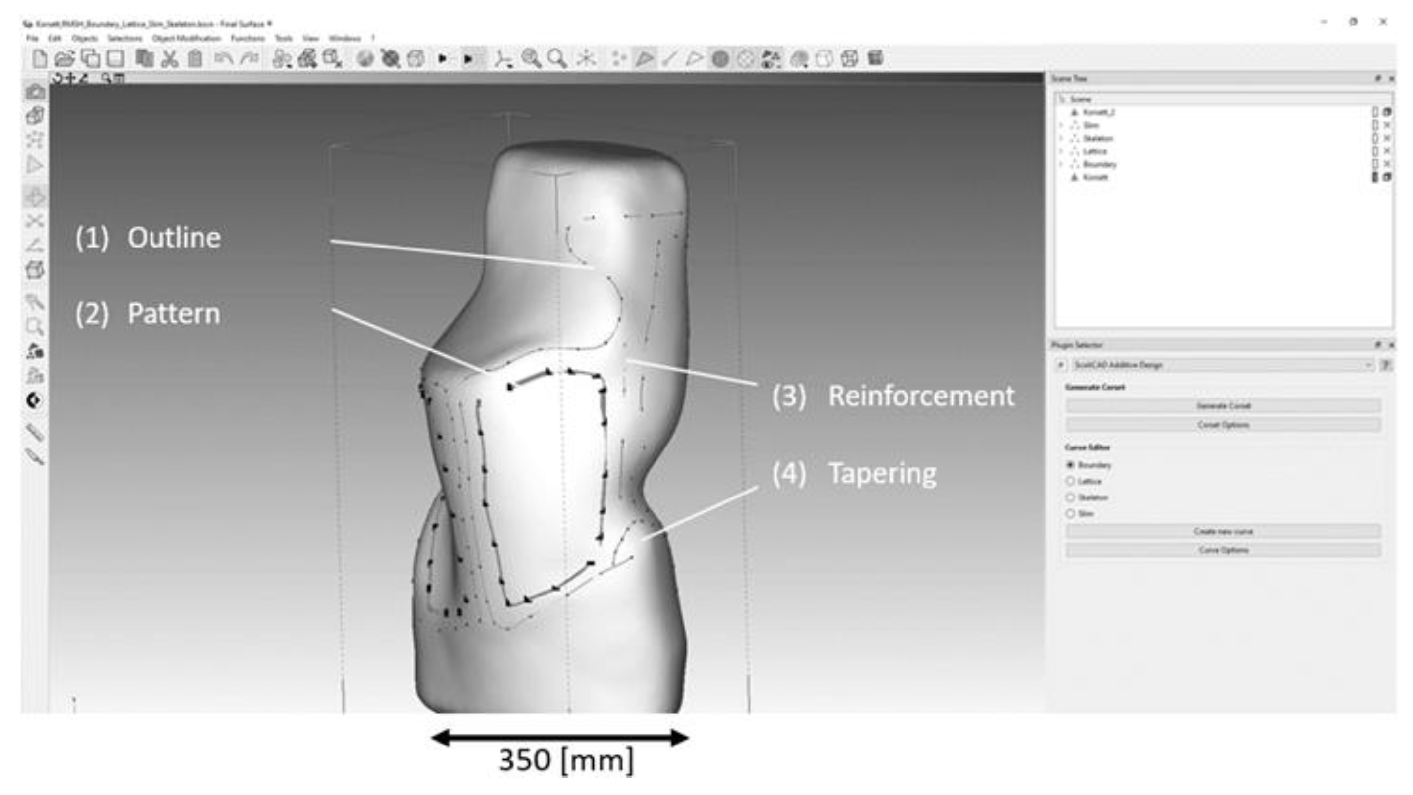
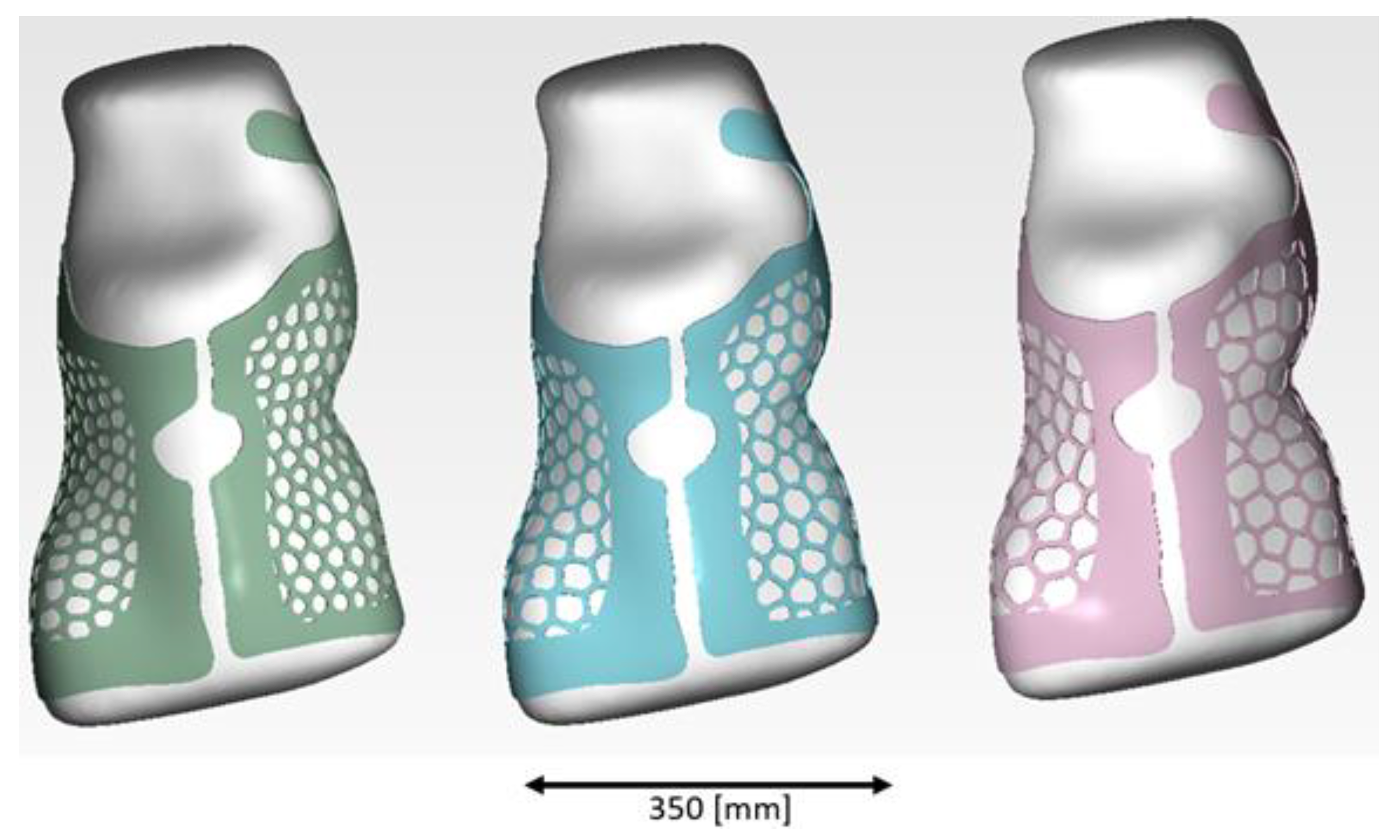
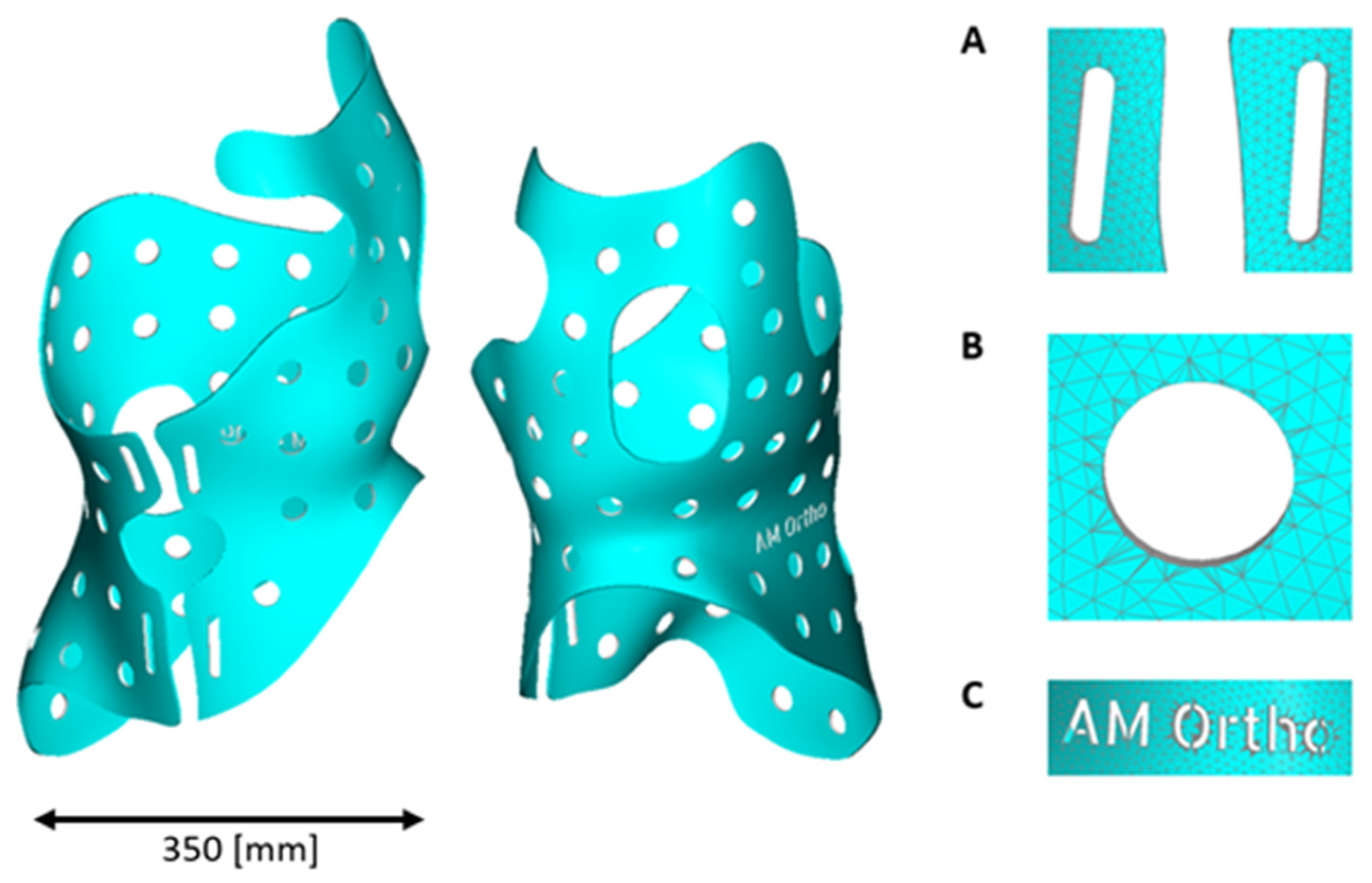
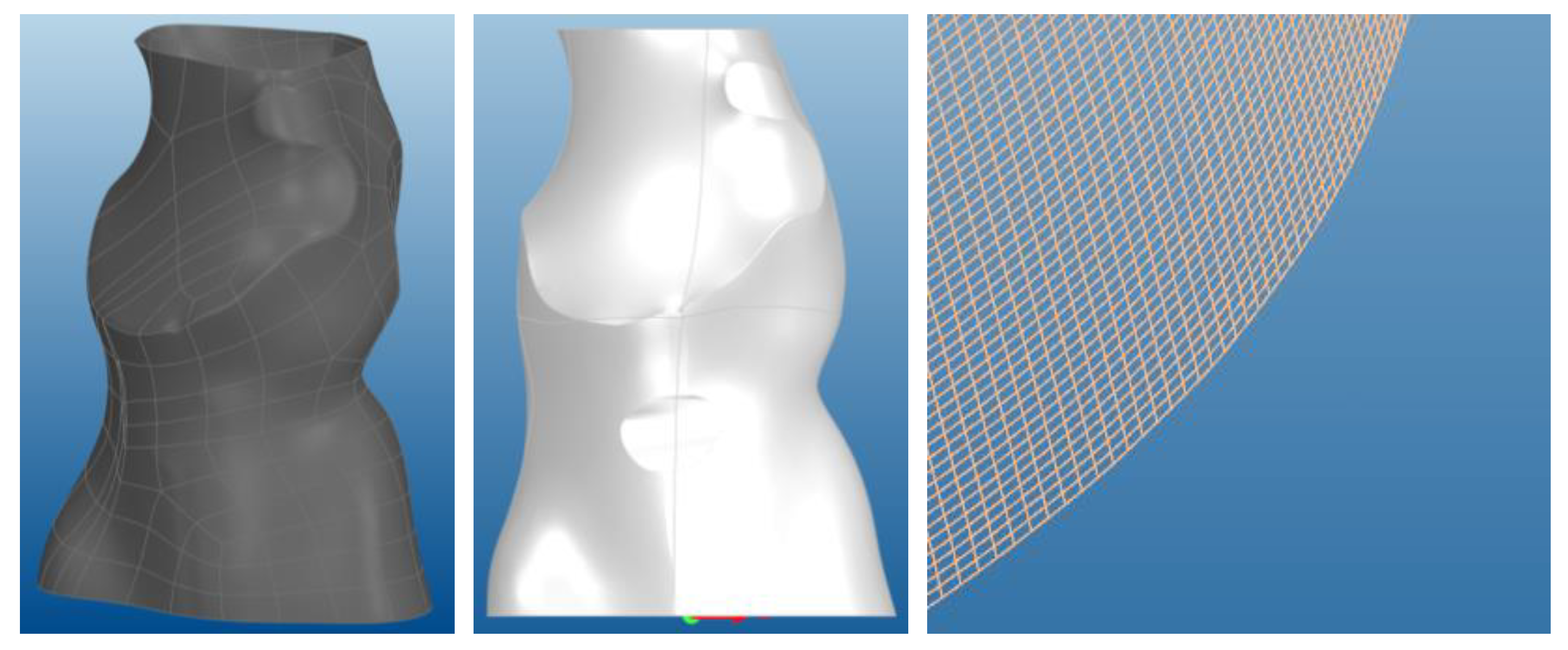
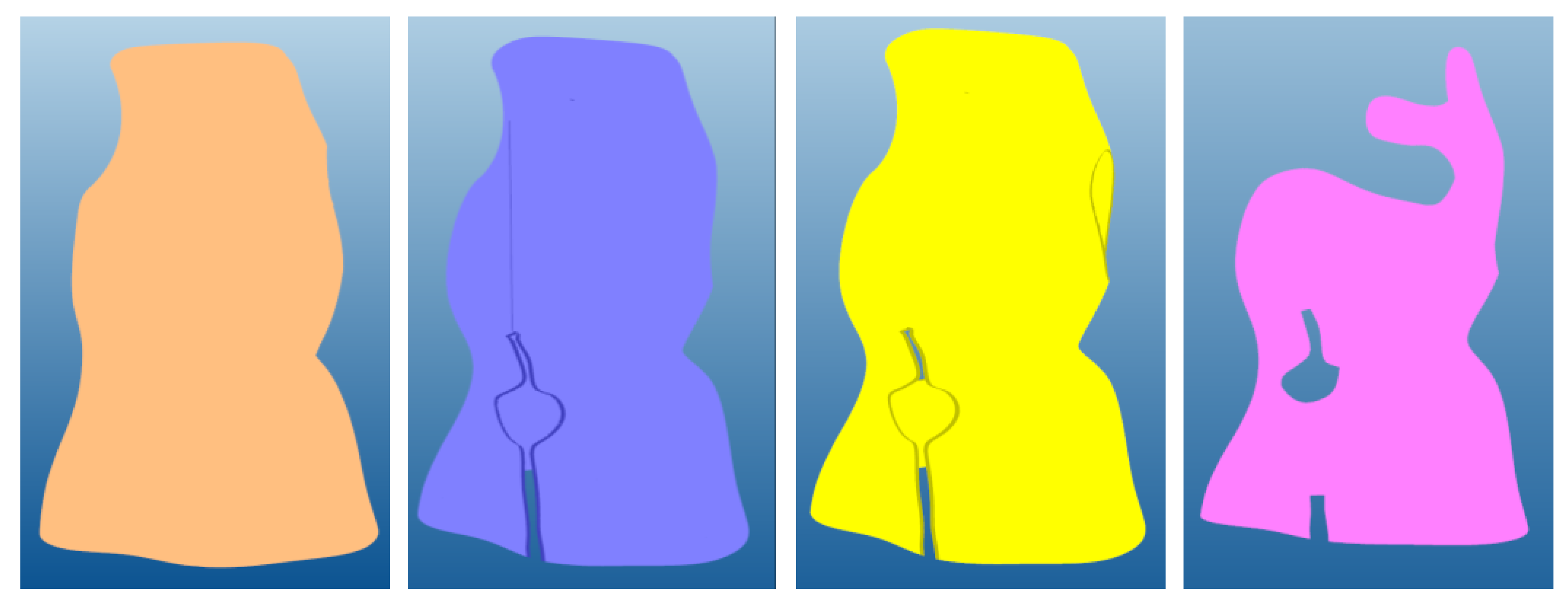
3.1. Model Generation
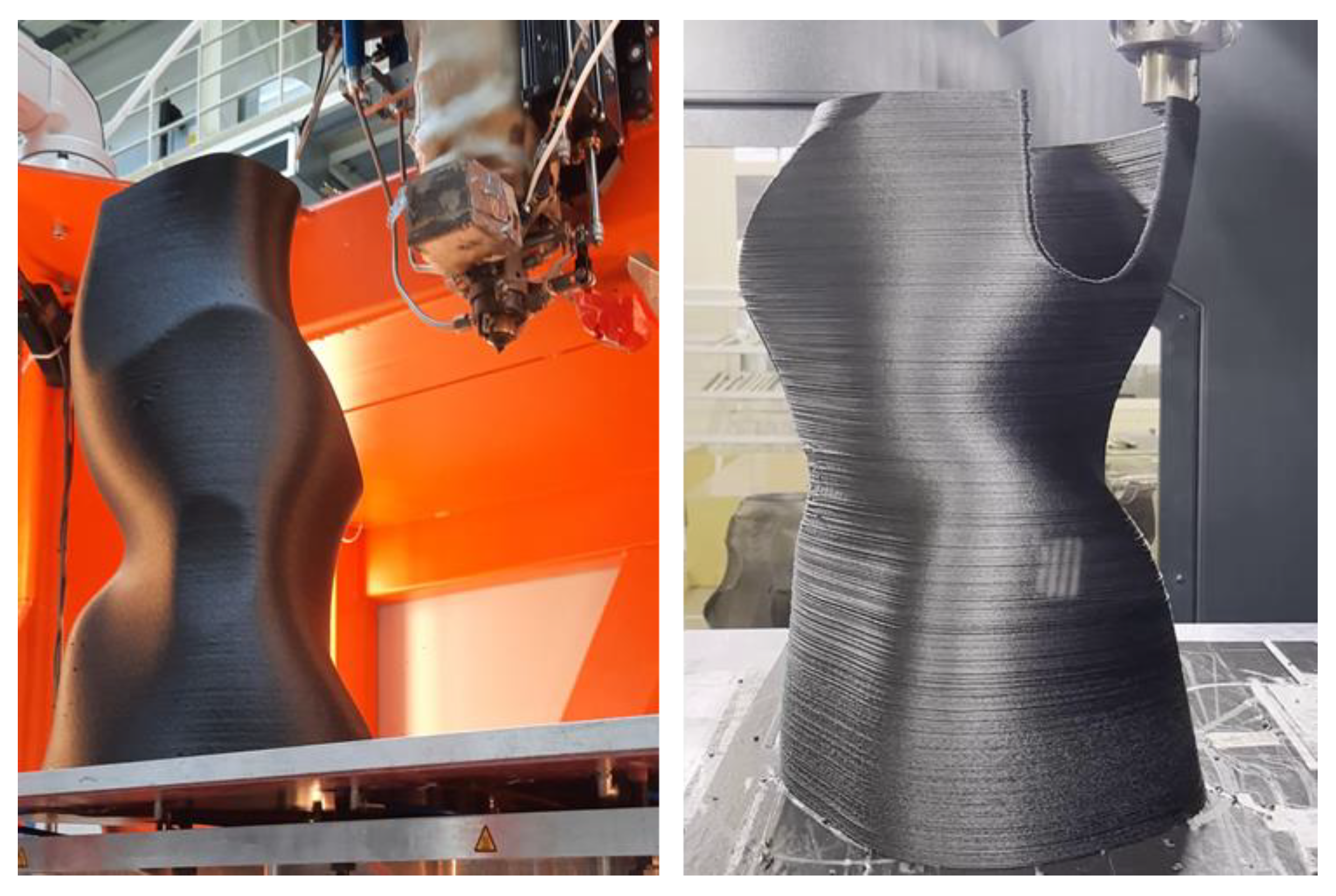
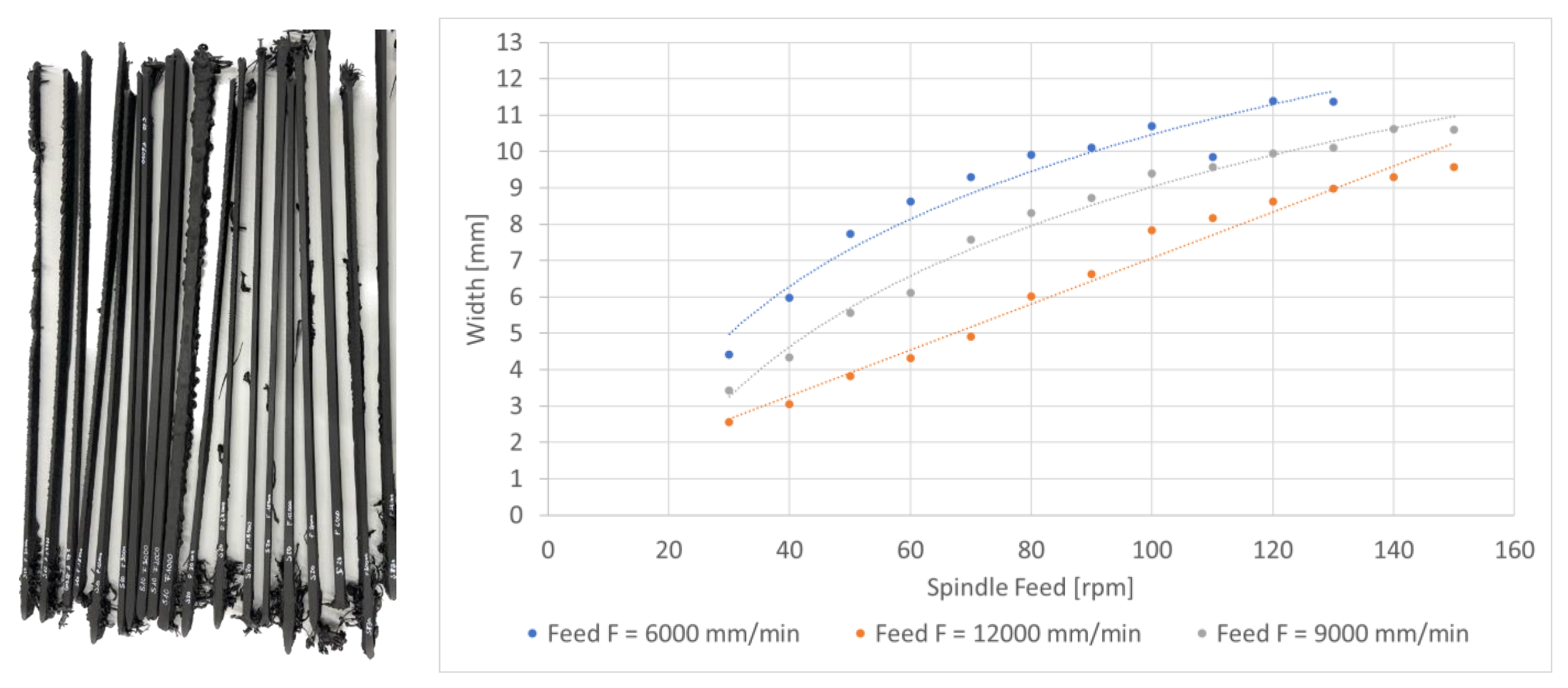
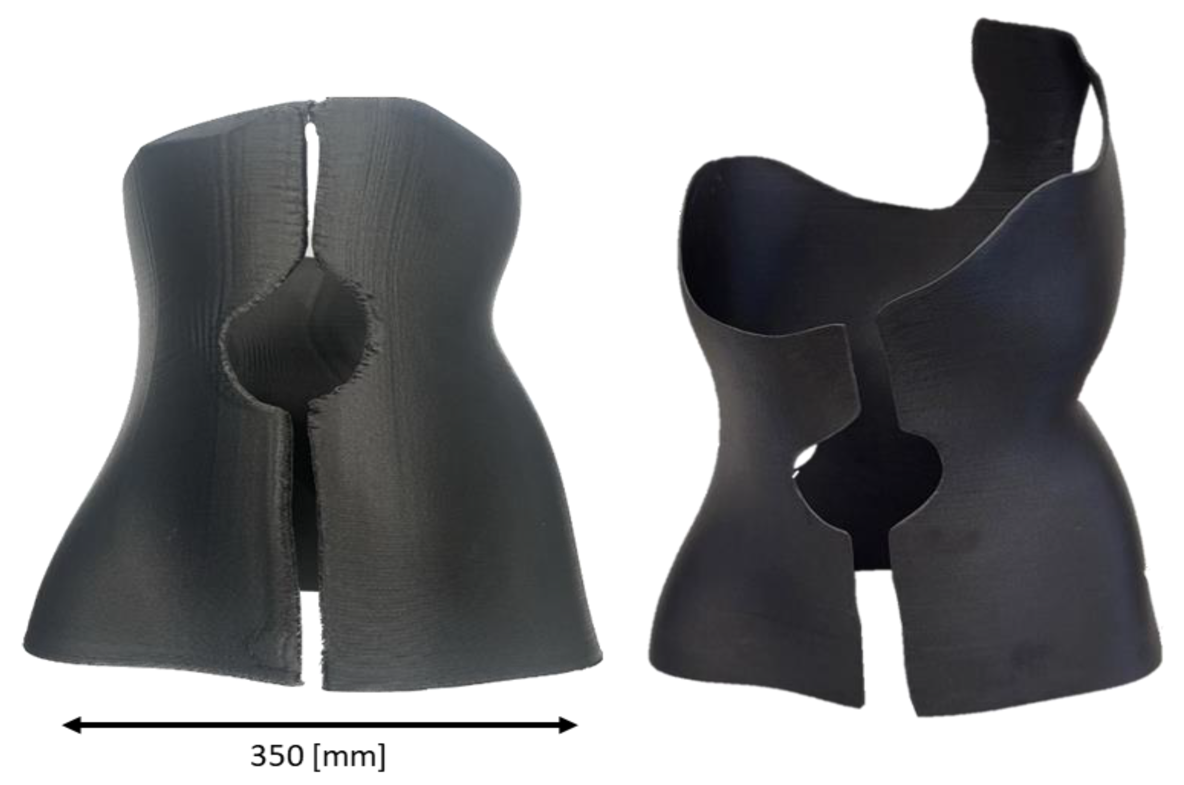
One of the main requirements with regard to the state of the art is the development of software tools for interactive modelling of printable brace and orthosis models with adaptation options for locally variable wall thicknesses (reinforcement, tapering, skeletonisation) and the insertion of ventilation cut-outs and patterns. For this purpose, an extension module for the Final Surface®—3D-Software v. 2022.0.3 with a graphical user interface (GUI) and the required graphical interaction and parameterisation options was developed [36]. Using an imported patient 3D scan (e.g., as a triangular mesh in STL format), the orthosis outer contour and cut-outs can be drawn on the 3D mesh model with the aid of spline functions. Individual points on the 3D surface can be selected through mouse picking and added to new or existing boundary objects. The software tool also enables manipulation of the position of existing spline-points. The dialogue includes functions for marking areas to be used as patterns, reinforcement, or tapering. All graphical interactions can be controlled interactively by selecting surface points and splines as three-dimensional boundary curves. For the three-dimensional modelling of the orthosis features, it is essential to create the splines as closed contours, which can be done semi-automatically in the software. Once all areas have been classified by closed splines in the object groups (edge, pattern, reinforcement, or taper), the model is extracted, and a 3D solid model is generated automatically. The process includes copying the top surface of the orthosis with a depth offset as well as generating edge elements in the gap between top and bottom surface. Next, the model can be exported to specific 3D printing pre-processing tools. Initially, a mesh export function was developed to solely depict the 2D middle surfaces of the orthoses, both for the orthosis surface and the support surfaces as presented in Figure 4. The software offers two export options for printable models: 3D volume or middle surfaces. This satisfies the requirements of different 3D printing processes.
The entire user interface was continuously harmonised with the clinical partner and has already been tested by a clinician. The final graphical user interface of the modelling software is shown in Figure 5.
Another important aim is to integrate cellular structures, such as holes and recesses, into the orthosis volume in order to modify the ventilation properties, aesthetic properties, and stiffness of the end product. For this purpose, fundamental algorithmic evaluations have been performed to enable the modelling and parameterisation of such structures. Among other things, the algorithmic foundations for randomly distributed point patterns (Poisson disc distribution) and parametric geometric basic shapes and patterns (triangle, square, hexagon, star, Voronoi cells) were developed. In this context, a final surface extension module has been created to model a parametric point distribution (Poisson’s disc, chessboard, hexahedron) and parametrically adaptable basic shapes (Voronoi, square, triangle, hexagon) in a previously defined ‘region of interest’ (ROI). The manual and automatic placement and integration of cell structures into the 3D orthotic model (using Boolean operations) has been realised in such a way that the module can be used to place and apply patterns either during the modelling of the orthosis or subsequently on the planned orthotic volume. Figure 6 shows the results of the module as an example of a Poisson disc distribution with a Voronoi structure integrated into a brace surface.
The patterns can be freely parameterised by the user in terms of position, spacing, and size. For better user-friendliness, however, consistent standard parameter sets have been predefined, which are available to the user as a selection.
In addition to the above-mentioned pattern generation functions, further software options have been created for the subsequent integration of functional elements such as closure openings or lettering on the orthosis volume. With the help of the extension module, a predefined closure opening (Figure 7A, oval) which can be parameterised in length and width, can be placed anywhere on the orthosis volume. Alternatively, it is possible to create lettering and place it anywhere on the orthosis. Once the design features have been placed, they are integrated into the orthosis volume using Boolean operations (Figure 7, left). The lettering feature was added at the request of orthopaedic technicians in order to allow subsequent marking of the orthoses with version numbers or names. This feature can be used as part of medical device tracking or as an aesthetic element and personalisation of the products. When compared to the state of the art, digital CAD modelling and 3D printing of braces offers advantages in terms of the patient’s comfort including breathability and weight reduction as well as customisation. These advantages are illustrated in Figure 6 and Figure 7 showing available aesthetic breathing patterns as well as customised functional features (text features, opening holes, breathing holes).

3.2. Manufacturing

After modelling a sample brace based on patient data from a medical project partner and making it available as an exportable 3D mesh (*.OBJ), a customised 3D brace model has been created using free-form surfaces without explicitly defined wall thickness and separate surfaces for the brace and the support structures as shown in Figure 4. In the next step and with the help of the DCAM software program of S.K.M. Informatik, vector contours are generated that correspond to the subsequent printing path from the imported 3D surface model (e.g., as a STEP file). Incorporating the pre-processing boundary conditions of the SEAMHex printer, the model is checked for printability so that openings and overlaps >45° were initially planned as support surfaces. Also, the orientation of the coordinate system must be adjusted in a way that the Z-axis points in the direction of assembly and the origin is centred in the first layer. The imported Polymesh model (Figure 8, left) is then converted into a UV mesh that is easier to process. With UV meshes, the surface is described in horizontal and vertical lines which, when spanned, result in a surface mesh (Figure 8, right).
By the use of an UV mesh, it is possible to print a body in a continuous spiral shape avoiding layer jumps, even when it is a partially non-closed body. To create the UV mesh, plane sections are created from the Polymesh model, which are then described by a spline with the same number of points. In a facet mesh, as in Figure 8, the plane sections act as U-lines, point-to-point connections result in the V-lines. A spiral is now placed in this mesh. The gradient of the spiral corresponds to the distance between the V-lines/the distance between the plane sections. In the final step, the outline contours of the recesses in the spiral model are cut out to create a continuous path. In a last step the orientation is recovered from the Polymesh to take advantage of the 5 DoF printing capability of the SEAMHex kinematic.
The initial printing strategy requires effortful post-processing to remove the support structures, displayed in Figure 4. To reduce post-processing, the model has been refined and the support structures have been removed step by step in an iterative process, Figure 9. Different strategies may be used for printing: while some contour elements require 5 DOF printing to avoid support structures, such as overhang elements (Figure 9, right), other segments can be planed and printed in a 2.5D manner.
While the first printing results include support structures to close the orthosis and layer jumps (Figure 10, left) improved planning results can be printed continuously in a spiral path and including cut-outs (Figure 10, right) that are realised immediately. For the implementation of the printing process including “gap jumps”, the bypass system of the SEAMHex printer is used: During printing, the nozzle is closed at the gap sections while the continuous movement corresponds to the closed model. This results in a reasonably constant layer time, which, in addition, simplifies the process parameter setting during production. To achieve high accuracy in the gap jump, a control integrated function was implemented to include the velocity planning results of the numerical control look-ahead functions and the time constants of the bypass system into the gap control algorithms with the Beckhoff TwinCAT control system. A video of the printing process is provided in the Supplement Material of the article (Video S1).
Further, modelling and optimisation of the output behaviour of the extruder were performed to investigate optimal parameter settings for printing. In experimental studies, multiple materials have been tested including polyamid (PA), polyethylen (PET), and medical-approved polypropylene (PP). Printing temperatures have been varied from 160 to 300 °C, pressures from 10 to 70 bar, bead widths from 2 to 11 mm, spindle feeds from 30 to 150 rpm, and velocity from 6 m/min to 12 m/min. In order to identify the influence of the process-relevant parameters on the resulting strand width, printing tests were planned, carried out, and analysed in the form of strand deposition tests on the SEAMHex2. The resulting pressure strips can be seen in Figure 11, left, and one corresponding exemplary evaluation in Figure 11, right. Calculable mathematical function models in the form of software objects with regard to process-optimised control strategies for the extruder were derived and implemented into the control system.
The printed result after a printing time of 2:30 h with cut-outs requires only low post- processing work, as displayed in Figure 12, left, where no processing was performed yet. Figure 12, right, shows a final post-processed 3D printed orthosis with a wall thickness of 2.5 mm.
Finally, the results were compared to the conventional scoliosis production process as well as to a conventional 2.5D printing process, as outlined in Table 1. In detail, when compared to the conventional scoliosis production, the production of the mould can be completely eliminated, which saves 20% of the time, 100% of the mould material, and about 30% of the total costs. The time-consuming manual thermoforming process of the brace is replaced by the automatic 3D printing process of the scoliosis brace, which, in addition to saving manual capacities, avoids waste of material due to near-net-shape production.
Compared to a conventional FFF printing process, SEAM additive printing on a granulate basis has material costs of around EUR 7/kg (PA6CF40) compared to EUR 80/kg for filament material. Further, the printing time of an orthosis using the SEAMHex printer is approx. 5 times faster with 2.5 h compared to 12 h using a conventional printer. The total price of an orthosis production without post-processing can be estimated to EUR 700 for conventional orthosis production, to EUR 256 for SEAM additive production, and EUR 792 for conventional 3D printing.

4. Conclusions and Outlook

In conclusion, the presented methods and tools allow the fast and support structure-free 3D printing of customised parts, such as orthosis, with low post-processing efforts. An important success of the work is the qualification of the SEAMHex high-performance extrusion printer for the additive in-time production of individual medical orthoses and the investigation of a digital process chain for the modelling of scoliosis braces. Particular challenges regarding the complex geometry of orthoses with multi-layered free-form surfaces, overhangs, and recesses were solved step by step in the project. For a clinically relevant brace model of a medical partner, a successful construction strategy with the material PP and convincing production times of less than 3 h was realised as an example. In addition to efficient additive manufacturing, a digital process chain was successfully analysed and implemented in the project. The software tools developed allow 3D modelling of the corrective form and the orthosis design until the path planning of a printable geometry using a 3D scan of the patient. The GUI control for creating the boundary curves can be managed via an intuitive mouse-click interaction, which was coordinated with the clinical partner. Further, the integration of extended, parametrically controllable functional elements such as breathing patterns, closure openings, lettering or the targeted, locally limited variation of wall thicknesses (reinforcement, tapering) in designated functional areas (border zones) is made possible. Consequently, the software tools developed enable the digital planning and production preparation of function-enhanced orthoses in an intuitive user interface with largely parametric or automatic design options. As the scoliosis braces can be produced in short printing times (<3 h) thanks to the efficient material output of the SEAMHex printer, there are economically relevant advantages compared to many conventional additive processes (>12 h). This enables the in-time production of orthoses and efficient machine utilisation, so that more patients can be treated in less time. Time-consuming production steps of the conventional manufacturing process (thermoforming), such as the subtractive production of a foam blank and its cost intensive storage for documentation purposes or as a back-up for repeated treatments, can be completely eliminated. Overall, the digital planning process allows for more effective patient care and transparent documentation of the treatment initially and in the follow-up. This can save costs and time when treating multiple patients repeatedly.
In future, structural openings (textures) can be incorporated into the orthosis, which increase wearing comfort (heat dissipation, weight) and thus acceptance. Cellularly linked structures and materials with graded properties (e.g., elasticity) offer a defined-limited deformability and can be integrated into certain areas of individually designed and 3D printed parts, just like 3D textures. Components such as closure elements or sensors can also be integrated into the component using these processes or the necessary openings can be provided directly. Utilising this potential also saves the technician additional time when fitting the orthosis.

Supplementary Materials

The following supporting information can be downloaded at: https://www.mdpi.com/article/10.3390/jmmp8020063/s1, Video S1: Printing process at SEAMHex2.

Author Contributions

Conceptualisation, S.R. and C.F.; methodology, S.R.; software, S.R.; validation, L.S. and S.R.; formal analysis, C.F.; investigation, L.S. and S.R.; resources, S.I.; data curation, L.S.; writing—original draft preparation, C.F.; writing—review and editing, C.F.; visualisation, S.R. and L.S.; supervision, S.I.; project administration, C.F.; funding acquisition, S.I. All authors have read and agreed to the published version of the manuscript.

Funding

This project was funded by the German Federal Ministry for Economic Affairs and Climate Action with the program Industrial Collective Research and the project AM-Ortho (21530 BG).

Data Availability Statement

Data available upon request due to restrictions.

Acknowledgments

The authors want to thank the editors and reviewers for their helpful comments and constructive suggestions with regard to the revision of this paper.

Conflicts of Interest

The authors declare no conflicts of interest. The funders had no role in the design of the study; in the collection, analyses, or interpretation of data; in the writing of the manuscript; or in the decision to publish the results.

References

  1. Asher, M.A.; Burton, D.C. Adolescent idiopathic scoliosis: Natural history and long term treatment effects. Scoliosis 2006, 1, 2. [Google Scholar] [CrossRef] [PubMed]
  2. Goldberg, C.J.; Moore, D.P.; Fogarty, E.E.; Dowling, F.E. Adolescent idiopathic scoliosis: Natural history and prognosis. In Research into Spinal Deformities 4; IOS Press: Amsterdam, The Netherlands, 2002; pp. 59–63. [Google Scholar]
  3. Weiss, H.-R.; Lehnert-Schroth, C.; Moramarco, M.; Moramarco, K. Schroth Therapy Advancements in Conservative Scoliosis Treatment, 3rd ed.; Book Publisher International (a part of SCIENCEDOMAIN International): New York, NY, USA, 2022; ISBN 9789355473219. [Google Scholar]
  4. Weiss, H.-R.; Tournavitis, N.; Nan, X.; Borysov, M.; Paul, L. Workflow of CAD/CAM Scoliosis Brace Adjustment in Preparation Using 3D Printing. Open Med. Inform. J. 2017, 11, 44–51. [Google Scholar] [CrossRef] [PubMed]
  5. Kaushik, A.; Gahletia, S.; Garg, R.K.; Sharma, P.; Chhabra, D.; Yadav, M. Advanced 3D body scanning techniques and its clinical applications. In Proceedings of the 2022 International Conference on Computational Modelling, Simulation and Optimization (ICCMSO), Pathum Thani, Thailand, 23–25 December 2022; IEEE: Piscataway, NJ, USA, 2022; pp. 352–358, ISBN 979-8-3503-3288-9. [Google Scholar]
  6. Creaform. HandySCAN 3D Series Metrology-Grade 3D Scanner Optimized for Large Parts. Available online: https://www.creaform3d.com/en (accessed on 20 November 2023).
  7. Artec3D. Eva Fast Structured Light 3D Scanner for Professionals. Available online: https://www.artec3d.com/de/portable-3d-scanners/artec-eva (accessed on 20 November 2023).
  8. SMARTTECH 3D. 3D Scanning Technology to Digitizing the Human Body. Available online: https://smarttech3dscanner.com/3d-scanners/smarttech3d-med/ (accessed on 20 November 2023).
  9. 3D SYSTEMS. Geomagic. Available online: https://de.3dsystems.com/software (accessed on 20 November 2023).
  10. Helle, R.H.; Lemu, H.G. A case study on use of 3D scanning for reverse engineering and quality control. Mater. Today Proc. 2021, 45, 5255–5262. [Google Scholar] [CrossRef]
  11. Weiss, H.R.; Seibel, S.; Moramarco, M.; Kleban, A. Bracing scoliosis: The evolution to CAD/CAM for improved in-brace corrections. Hard Tissue 2013, 2, 43. [Google Scholar] [CrossRef]
  12. Rothstock, S.; Weiss, H.-R.; Krueger, D.; Kleban, V.; Paul, L. Innovative Decision Support for Scoliosis Brace Therapy Based on Statistical Modelling of Markerless 3d Trunk Surface Data. Comput. Methods Biomech. Biomed. Eng. 2020, 23, 923–933. [Google Scholar] [CrossRef] [PubMed]
  13. Rigo, M.; Chêneau, J. Praxis der Chêneau-Korsettversorgung in der Skoliosetherapie; Thieme: Stuttgart, Germany, 2000; ISBN 9783131185419. [Google Scholar]
  14. Desbiens-Blais, F.; Clin, J.; Parent, S.; Labelle, H.; Aubin, C.-E. New brace design combining CAD/CAM and biomechanical simulation for the treatment of adolescent idiopathic scoliosis. Clin. Biomech. 2012, 27, 999–1005. [Google Scholar] [CrossRef] [PubMed]
  15. Sankar, W.N.; Albrektson, J.; Lerman, L.; Tolo, V.T.; Skaggs, D.L. Scoliosis in-brace curve correction and patient preference of CAD/CAM versus plaster molded TLSOs. J. Child. Orthop. 2007, 1, 345–349. [Google Scholar] [CrossRef] [PubMed]
  16. Vorum. CAD/CAM and 3D Printing Solutions for Orthotics and Prosthetics Providers. Available online: https://vorum.com/op-solution-overview/ (accessed on 18 December 2023).
  17. Rodin 4D. Software and Applications CAD/CAM. Available online: https://www.rodin4d.com/en/logiciel-cfao/ (accessed on 17 March 2024).
  18. Nathan, P.; Chou, S.M.; Liu, G. A review on different methods of scoliosis brace fabrication. Prosthet. Orthot. Int. 2023, 47, 424–433. [Google Scholar] [CrossRef] [PubMed]
  19. Lalegani Dezaki, M.; Mohd Ariffin, M.K.A.; Hatami, S. An overview of fused deposition modelling (FDM): Research, development and process optimisation. RPJ 2021, 27, 562–582. [Google Scholar] [CrossRef]
  20. Rothstock, S.; González-Ruiz, J.M.; Weiss, H.-R.; Turnbull, D.; Krueger, D. Severity and Cobb angle of scoliosis patients quantified with markerless trunk surface topography using k-NN search and multivariate regression analysis. Comput. Methods Biomech. Biomed. Eng. Imaging Vis. 2023, 11, 2433–2439. [Google Scholar] [CrossRef]
  21. Gefertec GmbH. Die 3DMP®-Prozesskette. Available online: https://www.gefertec.de/3dmp-verfahren/#prozesskette (accessed on 20 November 2023).
  22. Invet Medical. Company Invet Medical. Available online: https://www.inventmedical.com/de/start/ (accessed on 10 March 2024).
  23. 3Faktur. Available online: https://3faktur.com/3d-druck-in-der-orthopaedie/ (accessed on 12 March 2024).
  24. Ahrendt, D.; Schmitt, F.; Krzywinski, S.; Krzywinski, J. Bend-It—Rethinking Customized Orthopaedic Devices Using Additive Manufacturing; CONVERGE Europe: Essen, Germany, 2017. [Google Scholar]
  25. Hopmann, C.; Hellmich, C.; Lammert, N. Schichtweise vom Granulat zum Bauteil—Additive Fertigung von faserverstärkten PA6-Strukturbauteilen in hoher Geschwindigkeit. Kunststoffe 2018, 11, 22–25. [Google Scholar]
  26. IceSL. Product page IceSL. Available online: https://icesl.loria.fr/#header (accessed on 20 November 2023).
  27. Product Page OctoPrint. Available online: https://octoprint.org/ (accessed on 20 November 2023).
  28. Product Page Slic3r. Available online: http://slic3r.org/ (accessed on 20 November 2023).
  29. UltiMaker. Product Page Ultimaker Cura. Available online: https://ultimaker.com/software/ultimaker-cura/ (accessed on 20 November 2023).
  30. Blase, J.; John, C.; Kausch, M.; Witt, M. Ultrafast 3D printing. Kunststoffe Int. 2019, 11, 32–34. [Google Scholar]
  31. Ihlenfeldt, S.; Drossel, W.-G.; Kausch, M.; Friedrich, C.; Wiese, T.; Jankowsky, L. SEAMHex—Fast 6D Additive Manufacturing using an innovative Screw Extruder applied on a Hexapod Parallel Kinematic. TLS 2022, 5, 1–14. [Google Scholar] [CrossRef]
  32. Werner Pluta. Fraunhofer-Forscher Entwickeln Sehr Schnellen 3D-Drucker. Available online: https://www.golem.de/news/seam-fraunhofer-forscher-entwickeln-sehr-schnellen-3d-drucker-1904-140472.html (accessed on 20 November 2023).
  33. Friedrich, C.; Kauschinger, B.; Ihlenfeldt, S. Stiffness evaluation of a hexapod machine tool with integrated force sensors. J. Mach. Eng. 2020, 20, 58–69. [Google Scholar] [CrossRef]
  34. Wiese, T.; Abicht, J.; Friedrich, C.; Hellmich, A.; Ihlenfeldt, S. Flexible skill-based control for robot cells in manufacturing. Front. Robot. AI 2022, 9, 1014476. [Google Scholar] [CrossRef] [PubMed]
  35. Kauschinger, B.; Friedrich, C.; Zhou, R.; Ihlenfeldt, S. Fast Evaluation of the Volumetric Motion Accuracy of Multi-Axis Machine Tools using a Double-Ball-Bar. J. Mach. Eng. 2020, 20, 44–62. [Google Scholar] [CrossRef]
  36. GFaI e., V. Final Surface: 3D-Software zur Professionellen Erfassung, Visualisierung, Bearbeitung und Analyse von Komplexen 3D-Messdaten. Available online: https://www.final-surface.de (accessed on 12 March 2024).
Figure 1. Currently established orthosis production process and data flow.
Jmmp 08 00063 g001
Figure 2. Long-term goal of orthosis production and digitalised data flow.
Jmmp 08 00063 g002
Figure 3. SEAMHex2 3D Printer.
Jmmp 08 00063 g003
Figure 4. 2D middle surfaces of the orthoses, separately for the orthosis surface (light grey) and the support (dark grey).
Jmmp 08 00063 g004
Figure 5. Graphical user interface (GUI) of the modelling software for orthoses and braces.
Jmmp 08 00063 g005
Figure 6. Representation of a Voronoi pattern based on a Poisson disc distribution for different discrete cell distances (parametrically adjustable) integrated into a brace volume model.
Jmmp 08 00063 g006
Figure 7. Representation of a brace with subsequent integration of pattern and functional elements such as (A) closure openings, (B) breathing patterns, or (C) letters.
Jmmp 08 00063 g007
Figure 8. Polymesh brace (left), UV mesh (centre); details of the UV mesh (right).
Jmmp 08 00063 g008
Figure 9. Tool paths, iterative improvement from left to right by omitting the support structures, compared to Figure 4.
Jmmp 08 00063 g009
Figure 10. Closed orthosis with support structures at the SEAMHex 1 (left); continuous printing with cut-outs using the bypass system at the SEAMHex 2 (right).
Jmmp 08 00063 g010
Figure 11. 3D-printed strips from printing tests with varying parameters using a main nozzle of 2 mm diameter and the material Akromid PA6CF40 (left); exemplary evaluation of the printing tests with regard to spindle feed, feed forward, and bead width (right).
Jmmp 08 00063 g011
Figure 12. Non-post-processed print result without support structures (left); final post-processed 3D printed orthosis (right).
Jmmp 08 00063 g012
Table 1. Parameters, times, and cost for conventional and SEAM additive orthosis production as well as an estimation for conventional 2.5D additive printing for comparison.
PropertyPartConventional
Forming
SEAM
5 Axis Additive
Conventional
2.5D Additive
TechnologyMouldMilling--
BraceThermoforming3D Printing SEAM3D Printing FFF
MaterialMouldPolyurethane--
BracePolyethylenePA/PP/PET
Granulate
PA/PP
Filament
Manual workMouldNo--
BraceYesNoNo
WasteMouldca. 50%--
Braceca. 50%ca. 1–2%ca. 1–2%
WarehousingMouldNecessary--
Wall thicknessBrace3 mm2.5 mm2.5 mm
Manufacturing
Time
Mould30 min--
Brace2 h2.5 h12 h
Total2.5 h2.5 h12 h
CostsMouldEUR 200--
Brace Machining
Brace Material
EUR 5002.5 h × 100 EUR/h = EUR 250
0.9 kg × 7 EUR/kg = EUR 6
12 h × 60 EUR/h = EUR 720
0.9 kg × 80 EUR/kg = EUR 72
TotalEUR 700256EUR 792
Disclaimer/Publisher’s Note: The statements, opinions and data contained in all publications are solely those of the individual author(s) and contributor(s) and not of MDPI and/or the editor(s). MDPI and/or the editor(s) disclaim responsibility for any injury to people or property resulting from any ideas, methods, instructions or products referred to in the content.

