Article

Ultrasonic-Vibration-Superimposed Face Turning of Aluminium Matrix Composite Components for Enhancing Friction-Surface Preconditioning

1
Micromanufacturing Technology, Institute for Machine Tools and Production Processes, Chemnitz University of Technology, Reichenhainer Str. 70, 09126 Chemnitz, Germany
2
Materials and Surface Engineering, Institute of Materials Science and Engineering, Chemnitz University of Technology, Erfenschlager Str. 73, 09125 Chemnitz, Germany
*
Authors to whom correspondence should be addressed.
J. Manuf. Mater. Process. 2024, 8(1), 32; https://doi.org/10.3390/jmmp8010032
Submission received: 8 December 2023 / Revised: 24 January 2024 / Accepted: 29 January 2024 / Published: 7 February 2024
(This article belongs to the Special Issue Advances in Machining of Difficult-to-Cut Materials)

Abstract

:
Aluminium matrix composites (AMCs) represent an important group of high-performance materials. Due to their specific strength and a high thermal conductivity, these composites have been considered for the large-scale production of brake discs. However, preconditioning the friction surfaces is necessary to avoid severe wear of both the brake discs and the brake linings. This can be achieved through controlled friction against commercially available brake-lining materials and the formation of transfer or reactive layers (tribosurfaces). Homogeneous tribosurfaces allow for nearly wear-free brake systems under moderate brake conditions. In this work, preconditioning was carried out with a pin-on-disc tester, aiming for the fast creation of homogeneously formed and stable tribosurfaces. The influence of surface microedges perpendicular to the direction of friction on the machined AMC surfaces on the build-up speed and homogeneity of the tribosurfaces was investigated. The microedges were generated using ultrasonic-vibration-superimposed face turning. Thereby, the vibration direction corresponded to the direction of the passive force. For research purposes, the distance of the microedges was changed by varying the cutting speed and feed. The experiments were carried out using AMC disc specimens with a reinforcement content of a 35% volume proportion of silicon carbide particles. Machining was realised with CVD-diamond-tipped indexable inserts. The evaluation of the generated surfaces before and after preconditioning was achieved using 3D laser scanning microscopy and scanning electron microscopy. It was demonstrated that ultrasonic-vibration-superimposed face turning effectively generated microedges on the AMC surfaces. The results show that larger distances between the microedges enhanced the formation of stable tribosurfaces. Thus, the tribosystem’s steady state was reached quickly. Therefore, the benefits of AMC-friction-surface microstructuring on the generation of tribosurfaces under laboratory conditions were proven. These findings contribute to the development of high-performance AMC brake systems.

1. Introduction

The automotive industry represents one of the largest industrial sectors in the world. The demand for more sustainability, e.g., the responsible use of resources and a reduction in emissions, impacts this field significantly. Thus, in addition to decreasing the consumption of fossil fuels, weight savings through lightweight construction and materials are also in focus.
Brake discs are automotive components that can be substituted with lightweight materials [1]. However, since these safety-relevant components convert the kinetic energy of the automobile into thermal energy through friction during the braking process, specific material properties are demanded. While grey cast iron is used conventionally as a well-tested and reliable brake disc material, the above-described current requirements set aluminium matrix composites (AMCs) as alternative materials into the spotlight [2,3]. AMCs are characterised by a lower density and a higher corrosion resistance in comparison to grey cast iron. Furthermore, their thermal conductivity is higher [4]. In a friction pairing with conventional brake-lining material, AMCs show a braking behaviour similar to grey cast iron due to a comparable friction coefficient of 0.2–0.5 [5,6]. However, studies have shown that, after the finish-machining of AMC surfaces, further steps are necessary for their application as brake discs in vehicles. Specifically, a defined running-in of the brake discs has to be guaranteed, which can only be ensured by preconditioning the AMC friction surface to generate a tribosurface. This surface condition is supposed to prevent local pressure and, thus, significant temperature differences on the brake disc [7,8]. Natarajan et al. [9] investigated the friction and wear behaviour of AMCs against automotive brake-lining material. They found that the specific wear resistance of AMCs was higher than that of grey cast iron. Grupta et al. [10] examined the frictional wear of AMC pins with a reinforcement content of a 5–15% mass proportion in contact with a steel disc under test conditions similar to those used for automotive brake discs (sliding distance of 500 m–3000 m; sliding velocity of 1.6 m/s; pressure of 0.2 MPa, 0.6 MPa, and 1.0 MPa). It was observed that an increase in the percentage of reinforcement resulted in a reduction in the pin wear of 28–52%. A blackish so-called tribosurface was formed on the AMC’s friction zones, which acted as protection and improved the AMC’s wear resistance [7]. Eriksson et al. [11] reported that the performance of the AMC discs crucially depended on the formation of a tribosurface with a thickness in the range of 5–10 µm. For a wear-free condition of the brake disc, a minimum thickness of the tribosurface is required.
Former investigations by the authors of this paper on AMC friction surfaces showed that the kinematic roughness generated by face turning influences the formation behaviour of the tribosurface [12,13]. The results showed that specimen surfaces with higher values for the roughness led more quickly to a homogeneously closed tribosurface. AMC specimens with low surface roughness values required a longer run-in time to reach a stable friction condition compared to friction surfaces with higher roughness values. However, AMC friction surfaces with high roughness values strongly increased the abrasion of the brake-lining-material pin during preconditioning.
Ultrasonic-vibration-assisted turning is characterised by a superimposition of the tool motion with an ultrasonic vibration. A distinction can be made between one-dimensional (1D) and two-dimensional (2D) vibration assistance by considering the direction of vibration. Turning with a vibration in the cutting direction is a 1D method. In this case, a comparatively low cutting speed vc ensures that the tool is temporarily not in contact with the workpiece. The temporary disengagement of the tool can reduce its wear as well as the surface roughness values and burr formation. However, the machining time increases significantly. Zhong and Lin [14] analysed the effects of ultrasonic vibration assistance in the cutting direction when turning an aluminium alloy and an AMC reinforced with a 20% volume proportion of SiCp by applying single-crystal diamond tools. The authors found that turning with vibrations resulted in scale-like surfaces. However, ultrasonic vibration assistance led to a slight decrease in the surface roughness values of the aluminium alloy. In the case of AMCs, ultrasonic vibration involved a stronger reduction in the surface roughness values. Kim et al. and Bai et al. [15,16,17] investigated the advantages of ultrasonic vibration assistance in AMC turning by applying cemented carbide or PCD tools. They also found that, with ultrasonic vibration assistance in the cutting direction, a reduction in the surface roughness values was achieved. Bai et al. [15] discovered that a reduction in the surface roughness values was accompanied by a decrease in surface imperfections, because the loose SiC particles were not dragged between the specimen surface and the tool flank face, in contrast to turning without ultrasonic vibration assistance. Another possibility is to turn with vibration assistance in the direction of the feed motion, which leads to a changing feed velocity. Sinusoidal structures are generated on the workpiece surface in the cutting direction [18]. Ultrasonic vibration superimposition in the direction of the passive force is particularly suitable for the targeted generation of surface microstructures (Figure 1) [19,20,21,22]. The size of the corner radius influences the width of the microstructure and the clearance angle affects the shape in the cutting direction. The depth of the cut ap varies periodically with the sinusoidal oscillation.
Nestler and Schubert [23] showed that turning an aluminium matrix composite with ultrasonic vibration superimposition in the direction of the passive force led to regular surface microstructures. Furthermore, the surface imperfections were reduced. One of the most important applications for the microstructuring of surfaces is the influence of friction. Consequently, ultrasonic-vibration-superimposed turning can be suitable for machining AMC friction surfaces.
When turning with two-dimensional ultrasonic vibration assistance, the path of the tool corner changes to an elliptical or diagonal line depending on the phase difference between the two vibrations. Tong et al. [24] investigated the ultrasonic-vibration-assisted external turning of an aluminium alloy with cemented carbide tools. The vibration assistance was in both the cutting direction and the direction of the feed motion. The experimental results showed that the ultrasonic amplitude and the feed had the most significant effects on the surface microstructure. An increase in the feed led to a marked increase in the roughness values resulting from the kinematic surface microstructure. For large amplitudes, the time of tool disengagement increased and the surface microstructures were more pronounced. Furthermore, overlapping the two neighbouring elliptical paths in the direction of the feed motion reduced the height difference of the surface, resulting in textured surfaces with slightly reduced roughness values. Lu et al. [25] investigated external turning with two-dimensional ultrasonic vibration assistance in the cutting direction and the direction of the passive force. The specimen material used was an AMC with a 25% volume proportion of SiCp. For the experiment, PCD-tipped tools were applied. The researchers found that the elliptical vibration reduced the friction between the tool rake face and the chip due to better chip breaking, which resulted in shorter chips compared to turning without ultrasonic vibration assistance. As a consequence, the cutting force and energy were significantly reduced, and a high-quality surface finish was achieved. Zhou et al. [26] described the effect of two-dimensional ultrasonic vibration assistance in the cutting direction and the direction of the feed motion in the face turning of an AMC reinforced with a 25% volume proportion of SiCp. PCD tools were utilised in the experiments. It was found that the surface machined with two-dimensional ultrasonic vibration assistance had roughness values (Ra, Rz) approximately 80% lower than those of the surface machined without vibration assistance. The evenly distributed SiC particles, which were fractured during the cutting process, partially filled the pits and grooves on the surface.
In this study, disc-shaped AMC specimens were face-turned with a superimposition of ultrasonic vibrations in the direction of the passive force. The aim of the ultrasonic vibration superimposition was to generate defined microedges on the AMC surface. To prepare these surfaces for braking applications, they were tribologically preconditioned through dry sliding against standard brake-lining material.

2. Materials and Methods
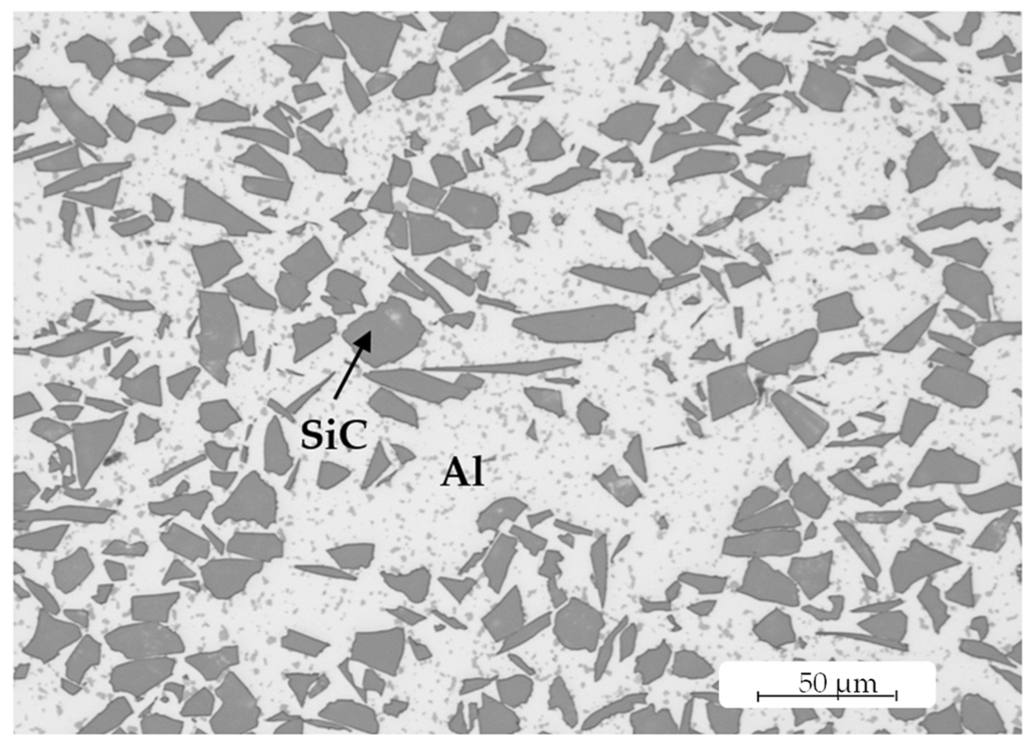
2.1. Specimens

For the experimental investigations, field-assisted sintered AMC discs were used. The material was AlSi7Mg (EN AC-42000 [27]), reinforced by polygonal SiC particles with an average size of about 20 µm in a volume fraction of 35%. Both the matrix and the reinforcement material, as well as the reinforcement shape, size, and content, were chosen with regard to a possible use in car braking systems. Figure 2 represents the AMC microstructure. The SiCp phase was homogeneously distributed in the aluminium matrix. The mechanical properties as well as the production parameters are described in [28]. The AMC exhibited a hardness of 99 ± 2 HB 62.5/2.5 and a yield strength of 179 ± 5 MPa. From each produced disc sinter body with a diameter of 200 mm and an average thickness of 14 mm, cylindrical specimens were cut out using abrasive water jet cutting and turned to a diameter of 55 mm and a thickness of 10.45 mm. In the tribological experiments, cylindrical pins of a common semi-metallic brake-lining material were used as counter bodies. They contained the elements Ba, Ca, Cu, K, Mg, Mn, S, Si, Sn, Ti, V, Zn, and Zr (comp. with Hirsch et al. [13]).

2.2. Cutting Tools

To machine the specimens, CVD-diamond-tipped indexable inserts of the type CCGW 09T3xx, exhibiting a sharp cutting edge, were used. The tools showed a rhombic shape with a tool included angle of 80°, a rake angle of 0°, and a clearance angle of 7°. The alignment of the added ultrasonic sonotrode was chosen in such a way that the indexable insert had a nominal cutting edge angle of 50°. The corner radius of the tools was varied (0.2 mm; 0.8 mm; 1.2 mm) to modify the shape of the microstructures in the direction of the feed motion.

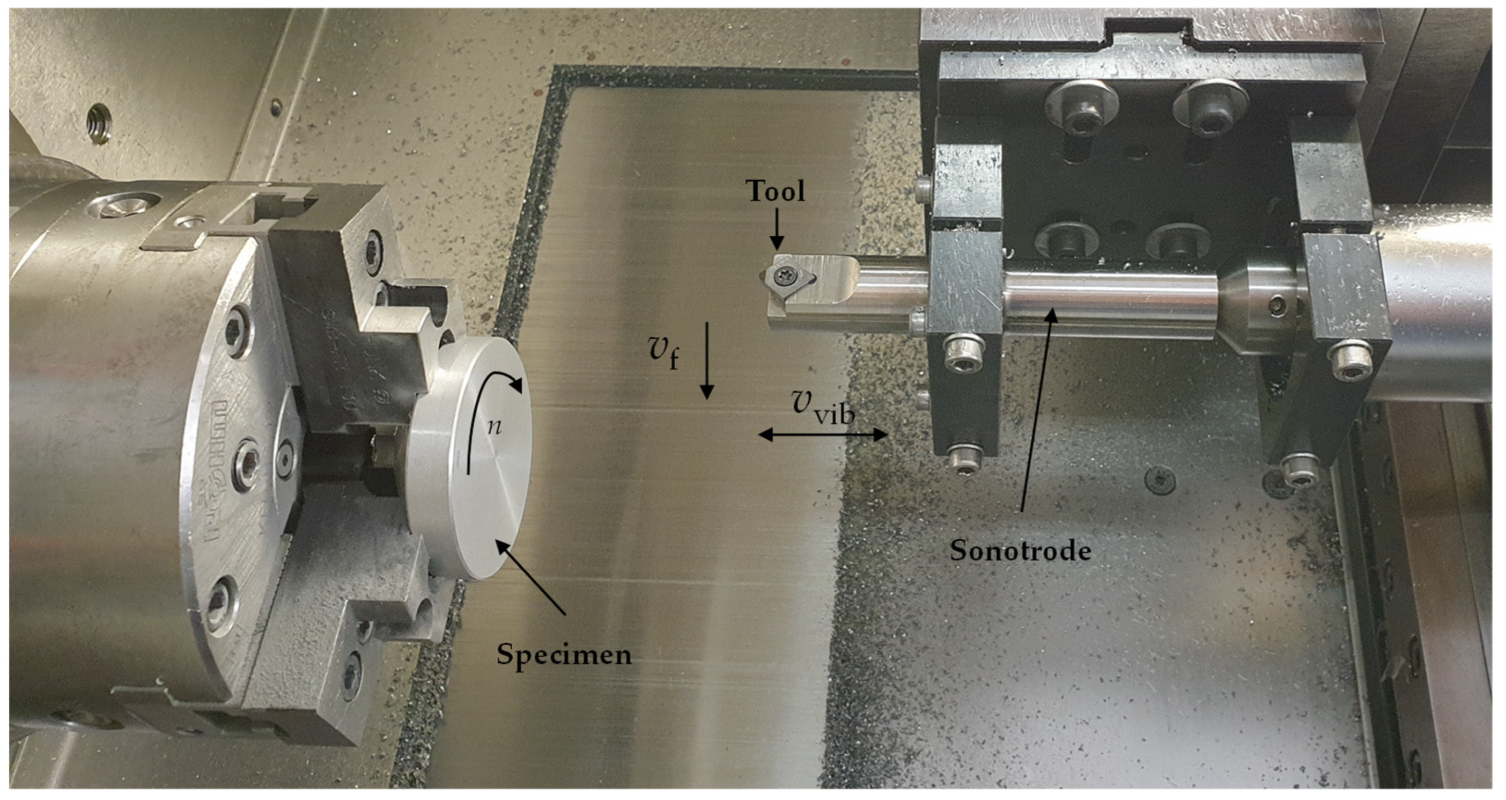
2.3. Machining Experiments

Machining was carried out on a SPINNER PD 32 precision lathe under dry conditions. The specimens were clamped on the outer diameter with the three-jaw chuck. In order to ensure a good axial run-out during the tests, the specimens were pre-machined to a thickness of 10.2 mm using a separate indexable insert of type CCGW 09T308. The feed for pre-machining was 0.15 mm and the cutting speed amounted to 250 m/min. For both the pre- and finish-machining experiments, the depth of the cut was 0.25 mm. The applied ultrasonic frequency fUS of approximately 24 kHz was close to the resonance frequency of the system. Figure 3 shows the working space of the lathe with the experimental setup and the directions of the movements.
The aimed surface microstructures on the machined specimen faces were to be generated by the corner radius of the tools without engaging the minor cutting edge. An amplitude A of 2 µm was kept constant for all tests. The cutting speed vc (100 m/min; 150 m/min) was combined with the feed f (0.05 mm; 0.1 mm). Special attention was paid to the parameter combinations vc = 100 m/min/f = 0.05 mm, referred to as small edge distances, and vc = 150 m/min/f = 0.1 mm, referred to as large edge distances (Figure 4). Due to the small clearance angle of the indexable inserts (7°), a temporary contact of the flank face with the specimen surface was expected at the low cutting speed, vc = 100 m/min. With regard to the subsequent tribological tests, the aim was to create surfaces with microedges perpendicular to the cutting direction. The size of the single microstructures (dimples) was varied in both the cutting direction and the direction of the feed motion, striving for surfaces with a different number of microedges per area. The dimension of the single microstructures in the radial direction df corresponded to the feed f. For the cutting direction, the dimension dc can be calculated with the following equation:
d c = v c f U S
This resulted in a dimension dc of 69 µm for a cutting speed of 100 m/min and a value of 104 µm for 150 m/min. Figure 4 shows simulated surfaces drawn up with a user-written MATLAB programme for ultrasonic-vibration-superimposed face turning (MATLAB 2019a, MathWorks, Natick, MA, USA). These simulated surfaces represented the theoretical surface microstructures without considering any material properties or tool wear. The surfaces showed an offset of the microstructures in the cutting direction (Figure 4c). For face turning, this offset resulted from the varying length of the cutting tool path per revolution. Furthermore, the offset was influenced by the non-integer part of the quotient of the ultrasonic frequency and the spindle speed, as well as their fluctuations.
Three test specimens were machined for each parameter set. One indexable insert was used per corner radius. In order to ensure a constant cutting speed during face turning by increasing the rotational speed n, the feed motion was stopped when a diameter of 15 mm was achieved.

2.4. Tribological Surface Conditioning Using Pin-on-Disc Test

The machined AMC specimens were prepared for the tribological test according to previous investigations [12,13]. The AMC specimens were fixed in a pin-on-disc test bench (SRV, Optimol Instruments Prüftechnik GmbH, Munich, Germany). After heating up the test setup to a temperature of 130 °C, a sliding velocity of 2 m/s at an average (disc) diameter of 21 mm was set. The aim was to avoid any additional temperature increases due to frictional heat and, thus, to ensure the comparability of the tribologically relevant parameters (µ and adjustment relevelling rate). The preliminary testing temperature was set at 130 °C, which is the maximum temperature that can be reached for the sliding velocity and pressure (2 MPa) applied. Pins from brake-lining material (one for each AMC disc) with a diameter of 6 mm were pushed against the machined AMC surfaces. To create the expected tribosurfaces, this tribological pairing was run under load progression up to the test pressure over a total distance of 245 m, 65 m of which at a constant pressure. The number of rotations/local passages during the test duration was, therefore, about 3.700, and was similar for each conducted test. A detailed description of the setup and parameter identification has already been published ([13]). To identify the differences between the surface microstructures generated by various face-turning parameters and tribosurface formation, the pin-on-disc test parameters were evaluated. Firstly, the change in the length of the brake-lining material pin was documented. Secondly, the mean friction coefficient and the adjustment relevelling rate (AR rate, see [13]) were determined, as soon as the progressively increased test pressure, and thus, the systems’ friction condition, were constant.

2.5. Surface Evaluation and Microstructural Analysis

Both the machined and test surfaces were analysed using 3D laser scanning microscopy (VK-9700, Keyence Corporation, Osaka, Japan). For each specimen, a stitched measuring area was analysed using a 50× objective. The same position was observed on each specimen before and after the tribological test. The respective area had a size of 2 mm × 2 mm. Software (MountainsMap 7.4, Digital Surf, Besançon, France) was used for the evaluation of the surfaces by applying different mathematical operations. After aligning the surface, shape deviations were removed by a 5th-degree polynomial. Due to the porous surface, a robust Gaussian filter was applied. The nesting index of the robust Gaussian filter was selected according to standard DIN EN ISO 25178-3 [29], and it amounted to 0.25 mm. For each specimen, the arithmetical mean height (Sa), the reduced peak height (Spk), and the peak material volume (Vmp) were determined before and after the tribological test.
To evaluate the AMC specimen surfaces, micrographs before and after the tribological tests were taken using scanning electron microscopy (SEM), both perpendicular to the surfaces and in a specimen tilt angle of 60°. The observed areas were analysed in terms of their uniformity and the areal completeness of the pin material transfer. In addition, cross-sections of the specimens, cut perpendicular to the tribosurface tracks, were prepared. Representative cross-sectional micrographs were employed to characterise the built-up state of the tribosurface, i.e., the thickness, shape, and uniformity.

3. Results and Discussion

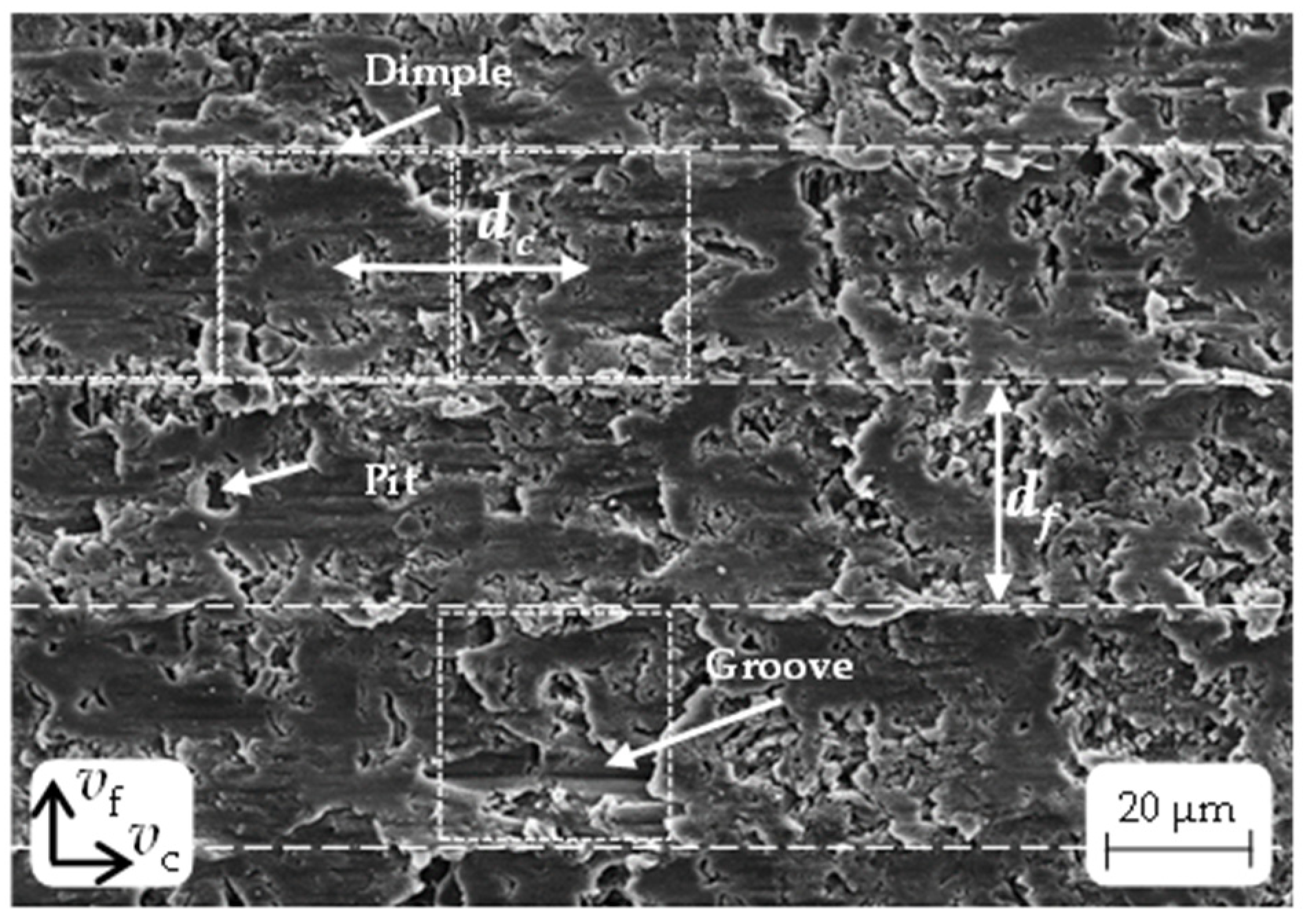
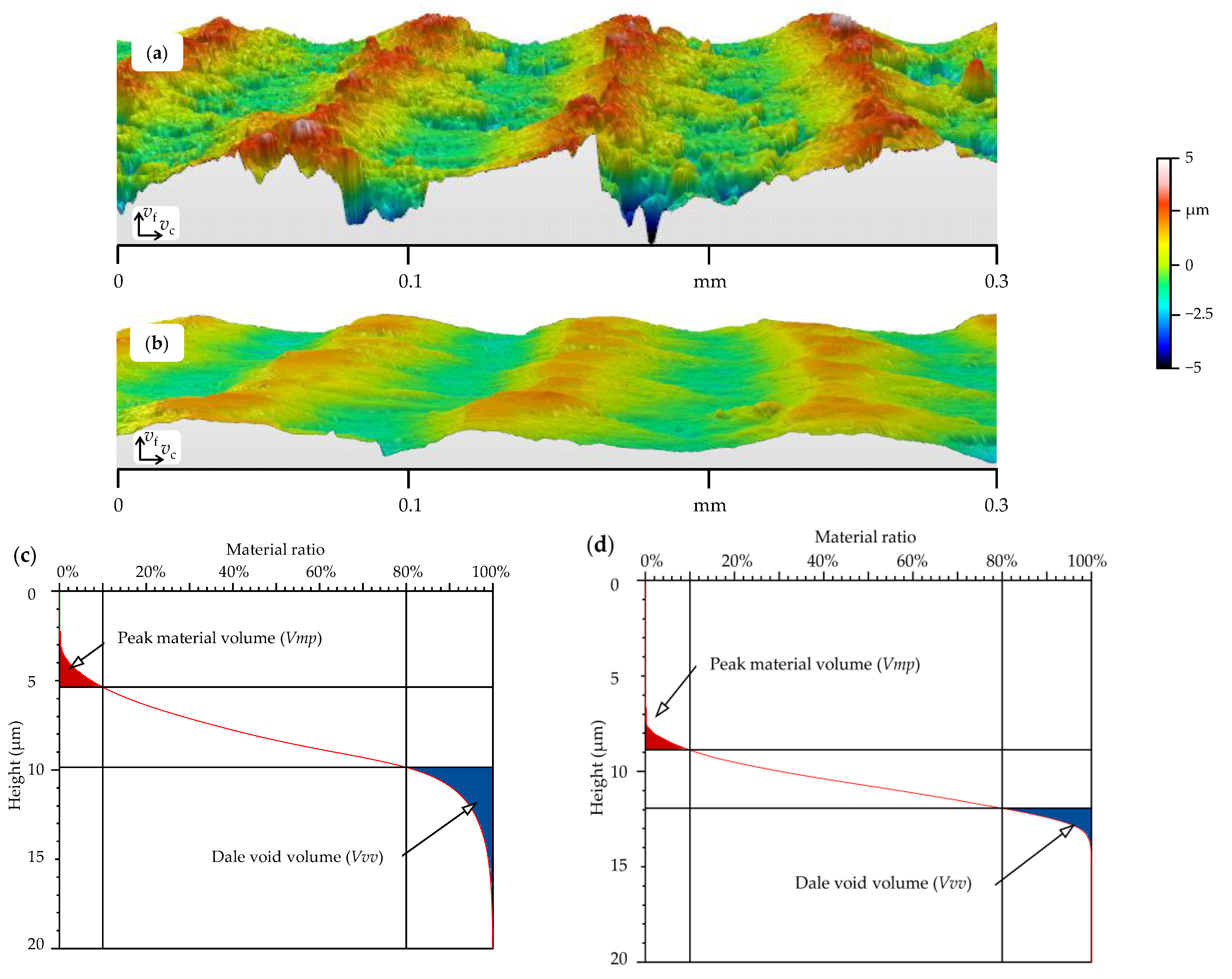
3.1. Surface Microstructure

Figure 5 exhibits a comparison of the simulated surfaces with the surfaces before and after the tribological pin-on-disc test. The simulated surfaces (a, d, g, and j) indicated that different microstructures can be generated by ultrasonic vibration superimposition in the direction of the passive force, in conjunction with a change in the cutting speed and feed. The focus was on the generation of microedges perpendicular to the cutting direction in order to generate high brake-lining material abrasion in the subsequent pin-on-disc test and, thus, a fast tribosurface build-up. The selection of the 3D surface profiles was confined to specimen surfaces with small edge distances (df = 50 µm; dc = 69 µm) and large edge distances (df = 100 µm; dc = 104 µm). The microstructure dimension dc was primarily responsible for the number of structural ridges generated. The variation from dc = 69 µm to dc = 104 µm resulted in a reduction in the number of ridges by 33%. It is noticeable that, in Figure 5e, the structural ridges correspond to the cutting direction. This is due to the fact that, with the combination of a small tool radius (rε = 0.2 mm) and a large edge distance in the direction of the feed motion (df = 100 µm), the kinematic roughness in the form of feed marks was predominant. In contrast, in Figure 5a,g,j, the kinematic roughness is more strongly superimposed by the sinusoidal shape of the ultrasonic movement.
The effective cutting speed was varied by the ultrasonic vibration superimposition of the cutting tool in the direction of the passive force. This caused significant variation in the working rake angle and the working clearance angle (see the different positions of the tool in Figure 1). The dimensions of the microstructures presented in Section 2.3 were realised for most of the specimen surfaces. However, the surfaces that were machined with a small corner radius (rε = 0.2 mm) and parameters for the generation of small edge distances (df = 50 µm; dc = 69 µm) exhibited a deviating microstructure (Figure 5b). Compared to the large-edge-distance microstructures (Figure 5e), the small-edge-distance microstructures (Figure 5b) were less pronounced and more irregular. This surface microgeometry resulted from the temporary contact of the flank face and the specimen surface during machining. Furthermore, for a corner radius of 0.2 mm, the small-edge-distance surface exhibited significant deviations from the simulated surfaces. On the one hand, this was the result of the offset of the microstructures in the cutting direction (compare Figure 4c), which was accompanied by the interruption of the structural ridges. On the other hand, imperfections (pits, blue-coloured) were still visible on the specimen surfaces before the pin-on-disc test (b, e, h, and k). This was due to the SiC particles in the AMC. Machining caused the hard particles to be partially pulled out of the surface or crushed. This left imperfections in the form of pits and grooves on the surface (see Figure 6). As a consequence, there were peaks rather than ridges on the surface (Figure 5b). The smaller corner radius in combination with the higher vc resulted in a more uniform checkerboard pattern of the microstructures. Conversely, larger corner radii led to linear or undulated microstructures in the direction of the feed motion (Figure 1c). The vertical distance between the lowest point of the dales and the highest point of the peaks corresponded to twice the set amplitude and was 4 µm.
Figure 5c,f,i,l show the specimen surfaces after the pin-on-disc tests. It can be seen that the dimples and dales of the surface microstructures are shallower. This was caused by the filling with brake-lining material being abraded from the pin during the pin-on-disc test. In general, the microedges led to higher abrasion of the brake-lining material pin compared to surfaces resulting from conventional face turning with the same cutting parameters (see [13]). Consequently, deposits were detected in the dimples and dales. For all the surfaces after the pin-on-disc test (Figure 5c,f,i,l), only minor imperfections resulting from the SiC particles were seen. This means that friction material was deposited in the dimples, in the dales, and especially in the pits of the microstructures during preconditioning. The surfaces after the pin-on-disc test (Figure 5c,f,i,l) indicated that the friction movement between the brake-lining material pin and the AMC surface reduced the peaks of the ridges.
Figure 7 shows an example of a captured surface as a tilted and exaggerated representation of the structural ridges before and after the pin-on-disc test. Furthermore, the corresponding material ratio curves are illustrated.
The differences between (a) and (b) as well as between (c) and (d) demonstrate how the dales were filled. The reduction in the dale void volume (Vvv) by approximately 66% was particularly noticeable on the material ratio curves. The change in the peak material volume (Vmp) was significantly lower, at approximately 30%. Figure 8 shows the mean values and standard deviations of Sa for each parameter set (Section 2.3), including different corner radii before (blue) and after (grey) the pin-on-disc test. For comparison, the characteristic values of the simulated surfaces were added (orange). It can be seen that the trends in Sa (machined and simulated) were similar, but the values of the machined surfaces were approx. 25% higher. The deviations between the simulated and the face-turned surfaces were due to imperfections (grooves, pits) caused by pulled-out SiC particles (see Figure 6) in the machined AMC surface. Furthermore, for the cutting speed of 100 m/min, there was a temporary engagement of the tool flank face, which resulted in the deformation of the surface microstructures. Figure 8 clearly shows a significant influence of the feed and the corner radius on the surface parameter Sa. The cutting speed vc had a minor impact on Sa, especially for the simulated surfaces, since vc only influenced the length of the microstructures in the cutting direction and, thus, the number of microstructures, but not their height or width. However, there was a trend towards a slight increase in the roughness values for Sa with increasing cutting speed.
After the pin-on-disc test, the values for Sa amounted to approximately 50% compared to the surfaces before the pin-on-disc test. During preconditioning, the brake-lining material pin rubbed off on the disc surface, particularly on the peaks of the microedges. This caused some of the removed material to deposit itself in the dimples and dales as well as on the ridges of the microedges in the direction of movement. Consequently, these microstructure elements gradually filled up. The peaks of the ridges were only slightly abraded due to the hard SiC particles; however, they were flattened and broadened. Despite the fact that the created dimples and dales of the microstructures were only partially filled (see Figure 5c,f,i,l) within the short testing time, the values (Sa) were lower than before the pin-on-disc test. To identify the peak and ridge abrasion, Vmp and Spk were also evaluated before and after the pin-on-disc tests (see Figure 9).
Figure 9 exhibits the differences in the surface characteristics with respect to the tool corner radius and feed. For specimens machined with an indexable insert characterised by rε = 0.2 mm, there were significantly higher values for the peak material volume Vmp and the reduced peak height Spk compared to the surfaces generated with rε = 0.8 mm and rε = 1.2 mm, respectively. A change in the feed from 0.05 mm to 0.1 mm resulted in an increase in Spk and Vmp. An increase in the cutting speed led to only a slight rise in Vmp and Spk for all surfaces. This was due to the associated change (growth) in the microstructure size dc. After the pin-on-disc test, a significant decrease in Spk and Vmp was observed. This resulted from the abraded material of the pin, which was deposited in the dales during the pin-on-disc test and resulted in filled dales rather than ablated peaks. Levelling the surfaces led to an improved load-bearing capacity, which had a positive impact on the rubbing and wear performance. Figure 8 and Figure 9 show that increasing the corner radius had a minor influence on the surface characteristics. This can be explained by the fact that a modification of the radius only caused variation in the shape of the microstructure in the direction of the feed motion. Increasing the feed had the most prominent influence on Sa, Vmp, and Spk, and it involved higher surface values.

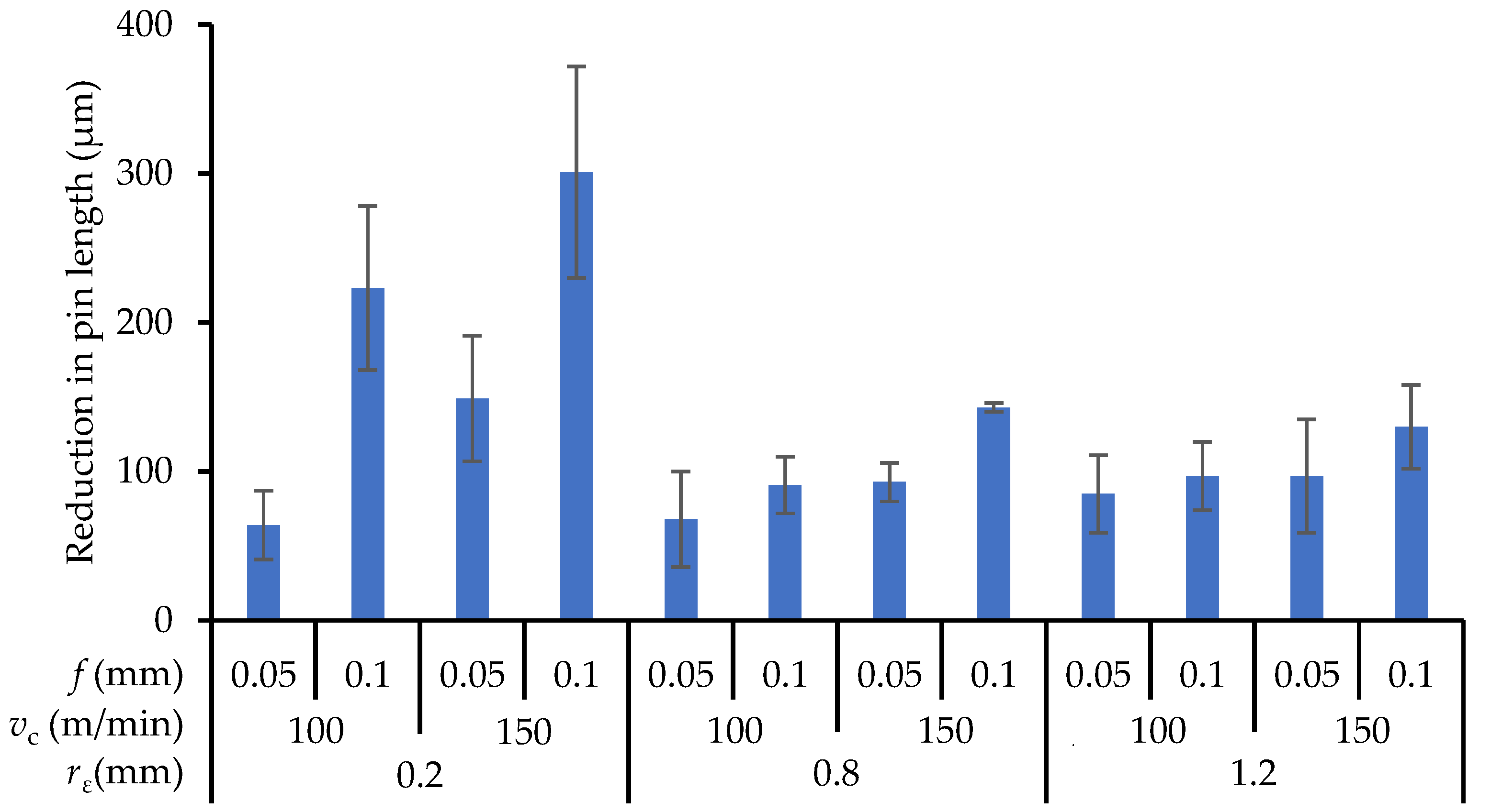
3.2. Tribological Considerations

Analogously to Hirsch et al. [13], the AR rate for each of the surface conditions was determined. Figure 10 displays the changes in the AR rate as a result of the conditions in ultrasonic-vibration-superimposed face turning. It was obvious that the acceleration of the pin material transfer led to an increase in the AR rate. The specimen surface, which was generated with a small corner radius (rε = 0.2 mm) and the parameters for the large-edge-distance surface (df = 100 µm, dc = 104 µm), showed the highest AR rate and reached 1.0 µm/m. Compared to this surface microstructure, the surface with the small edge distances (df = 50 µm, dc = 69 µm) generally involved the lowest AR rates. A similar trend was observed by Hirsch et al. [13]. When a tool with a corner radius of 0.2 mm or 0.8 mm was used, the AR rate increased by a factor of approximately four for the surface with large edge distances compared to the surface with small edge distances. For applying the tool with the corner radius 1.2 mm the AR rate doubled. The specimen surface had the lowest AR rate, of 0.1 µm/m, when applying the indexable insert with a corner radius of rε = 0.8 mm and parameters for small edge distances (df = 50 µm, dc = 69 µm). In addition, it was found that the AR rate (see Figure 10) compared to the Spk and Vmp values (shown in Figure 9 before and after the pin-on-disc tests) showed similar trends depending on the cutting parameters. In other words, if the Spk and Vmp values were the highest, the corresponding AR rate was also higher compared to the other results.
In order to evaluate the pin abrasion over the whole test length, the pin length variations were measured. Figure 11 shows the differences in the pin length depending on the face-turning parameters.
It can be seen that the pin loss for the specimens machined using the indexable insert with a corner radius of rε = 0.2 mm exhibited the largest and smallest values, depending on the distances of the microedges. For the large edge distances, the pin loss was higher than for the small ones. The diagram also shows slighter pin losses for the specimens machined with the corner radii rε = 0.8 mm and rε = 1.2 mm, regardless of the edge distances. This suggests that, with an increasing corner radius, the differences in the pin loss between small and large edge distances decreased. It should be noted, as mentioned before, that these results were consistent with the trends in the AR rate (Figure 10), indicating that the pin loss rose proportionately as the AR rate increased. This could be attributed to the abrasion effect of preconditioned tribosurfaces, which has been described in detail in a previous study [13]. The abrasion effects varied depending on whether surfaces with small or large edge distances were generated. It can be concluded from this that there is a dependency between the generated surface, here in particular, the Spk values, and the pin abrasion. Figure 12 depicts the Spk (from Figure 9) and the reduction in the pin length (from Figure 11) side by side. The strong correlation between these two parameters can be clearly seen.

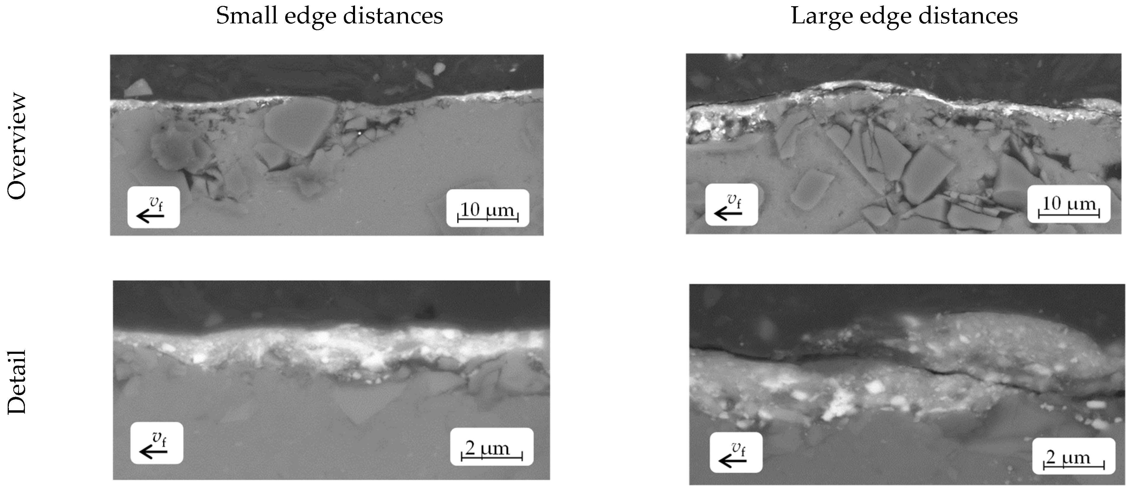
3.3. Microstructural Observations

The backscattered electron (BSE) micrographs in Figure 13 demonstrate the typical tribosurface build-up on preconditioned AMC specimens. Specimens machined with corner radii of 0.2 mm or 1.2 mm and parameters for small as well as large edge distances are shown in comparison. The influence of the surface microstructures created by the ultrasonic vibration superimposition (see Section 2.3) on the tribosurface formation is obvious. The areas in light grey show the transferred brake-lining material. The black-appearing areas are regions of the AMC disc that were uncovered by the transferred brake-lining material, i.e., showing the element contrast of the aluminium matrix and the SiC particles. The specimen surfaces with the large-edge-distance microstructures had a higher proportion of area of transferred brake-lining material compared to the surfaces with the small-edge-distance microstructures, which can be seen from the higher proportion of light grey regions.
When evaluating these observations under consideration of Figure 8, Figure 9 and Figure 12, it can be estimated that the surfaces with large edge distances, comprising the highest values for Sa, Spk, and Vmp, led to higher pin abrasion and more intensive pin material transfer to the AMC surface. This indicates a thicker and more even tribosurface, like those seen in Figure 13. In contrast, surfaces machined with a corner radius of 0.2 mm involved a decrease in the pin length to approximately 25% for the small-edge-distance compared to the large-edge-distance surfaces, as shown in Figure 11. Obviously, only a small amount of pin material was transferred to the specimen surfaces, which appeared much darker in the BSE images in comparison. This is consistent with the values of the AR rate, which experienced a four-fold increase for the surfaces with a corner radius of 0.2 mm from the small- to the large-edge-distance surfaces (see Figure 10).
Figure 14 shows secondary electron (SE) micrographs of the specimens with small- and large-edge-distance surfaces. The micrographs were taken under a specimen tilt angle of 60°. The specimen surfaces were observed before and after the pin-on-disc tests. The micrographs indicate that surface microstructures with large edge distances did not only provoke higher pin losses, but actually resulted in a more extensive tribosurface build-up. In comparison, small-edge-distance surfaces with a lower AR rate showed just a local and spot-like formation on the tribosurface. This confirmed the assumed trends discussed above.
The sufficiently high transfer of pin material to the microstructured AMC surfaces smoothed these surfaces and thereby reduced a locally high contact pressure by increasing the specific contact area. Thus, the tribological contact and friction conditions were homogenised and the wear performance was improved. In fact, for all the surfaces prepared with various ultrasonic-vibration-superimposition settings, the friction coefficient of the tested specimens was calculated to be roughly µ = 0.5. However, the results showed that the AR rate, mainly the pin material loss, varied significantly depending on the applied machining settings. Furthermore, the AR rate was higher when the surfaces with large edge distances were preconditioned. The BSE micrographs of the cross-sectional parts of the large-edge-distance microstructures (see Figure 15, right side) show a thicker, more continuous, and nearly closed tribosurface layer in comparison to cross-sections from small-edge-distance microstructures. But, they also comprised fragmented and cracked layer areas. This may have been caused by differences in the local coefficients of thermal expansion (CTE) between the tribolayer and the AMC body. The tribolayer was built from a mix of transferred brake-lining and worn-off-AMC material (including thermally oxidised wear debris), i.e., the chemical character of a high fraction of this layer was oxide-ceramic. In comparison to the adjacent AMC base material with its aluminium alloy matrix, the tribolayer had a much smaller CTE and thermal conductivity in addition to a significantly higher brittleness. After the tribological preconditioning at elevated temperatures, the cooling down of the tribolayer thus took longer, and this went along with a lower volume shrinkage. This, then, may have led to the observed diagonal cracks that locally released compressive stresses, which were thermally induced by the described test conditions and material characteristics. This phenomenon may have been further intensified at the “coarse” surfaces, which were represented by the large-edge-distance microstructures. The reduced number of edges per area of these comparatively coarse surfaces may have led to the localised or locally quicker formation of the tribolayer and, hence, it may have added additional local stress during cooling down due to the locally different material volumes. In addition, as a consequence of the comparatively wide microstructure patterns, the material removed from both the pin and the AMC body that formed the tribolayer could not be fully integrated into the surface microstructures, as it would have been for a finer surface, as represented by the small-edge-distance microstructures. Therefore, poorly adhering tribolayer volumes may occur locally, resulting in a more discontinuous tribological behaviour that was seen by the observed cracking. These interpretations are supported by the observed larger standard deviations for the AR rate of the large-edge-distance surfaces.
In comparison, the tribosurfaces with a small-edge-distance microstructure (see Figure 15, left side) appeared to be thinner and more unevenly distributed on the AMC surface, but more homogeneously built, i.e., no cracks or overlapping of single-layer material fragments occurred. Again, the more stable, but slower, tribosurface formation was confirmed by the AR rates, which showed lower values as well as a reduction in the pin loss. This was due to the smaller edge distances and the accompanying lower surface roughness values (see Figure 8 and Figure 9).
However, a significant loss in the brake-lining material pins (closely related to the present AMC surface microstructures) and the abrasive effect of the enclosed SiCp phase not only influenced the characteristics of the tribosurface, but they also played an essential role in the long-term use of AMC materials in brake disc applications. Therefore, a robust and fast tribosurface generation process is crucial to quickly obtain a steady-state tribological system. From previous studies on differently finish-machined AMC surfaces, it is known that they achieve stable tribological conditions only after long test periods [13]. Therefore, to efficiently integrate an AMC disc into a braking system, it is important to reduce the time that is needed for AMC surface preconditioning. The preconditioned state is thereby defined as a tribologically steady state, in which the coefficient of friction (COF) between the AMC disc and the brake lining is constant (for a given constant pressure) and the occurring wear is neglectable or linear with a low increase. The results of the short-term test performed in this research showed that the AR rate varied significantly depending on the surface microstructure (see Figure 10).

4. Summary and Conclusions

The objective of this study was to expedite the formation of a tribologically preconditioned surface (tribosurface) to attain a steady state in the tribological system between an AMC surface and a brake-lining material pin. Microstructures were produced on the specimens using ultrasonic superimposed face turning. The microstructures of the AMC surfaces exhibited edges, preferably ridges. Surfaces with small and large edge distances in both the cutting direction dc and the direction of the feed motion df were generated on the AMC surfaces by varying the cutting speed and the feed. The specimens underwent preconditioning using pins made from brake-lining material in a pin-on-disc tester.
During this process, the surface microedges caused high abrasion to the brake-lining material pin. The abraded pin material was embedded in the microstructures, specifically in the pits and dimples. The transfer of brake-lining material occurred at a higher AR rate compared to the investigations in [13]. Preconditioning the AMC surfaces with microedges resulted in a more rapid and even distribution of the tribolayer on the AMC surface. Tribological tests of the AMC surfaces showed that the surfaces with larger edge distances, generated using a corner radius of 0.2 mm, experienced the highest material loss on the brake-lining material pin in a pin-on-disc test setup. The generation of tribosurfaces was accelerated, resulting in more flattened and denser surfaces during pin material transfer. The reduction in the volume of the pin, measured by the pin length, can be predicted based on the surface parameter Spk. The coefficient of friction for all the test specimens fell within the required range for braking applications, at approximately 0.5. The abrasion of the AMC was low due to the presence of hard SiC particles, which acted as a load-bearing component and had an abrasive nature. Gultekin et al. [30] found in wear tests with copper matrix composite discs sliding against AMC discs that the brake-lining material (copper matrix composite) also experienced higher abrasion compared to the AMC disc. This was due to the ploughing of the pin material by the silicon carbide particles. Our results support this finding.
The results indicate that microstructured friction surfaces can be suitable for brake applications. However, up-scaling the preconditioning process to automotive brake discs requires the appropriate management of the brake disc temperature and a reduction in the preconditioning time. This can be achieved through friction path shortening. However, this approach presupposes further investigations into the high-speed preconditioning of AMC surfaces.

Author Contributions

Conceptualization, P.E.; methodology, P.E. and S.J.H.; formal analysis, P.E. and S.J.H.; investigation, P.E. and S.J.H.; resources, A.S. and T.L.; data curation, P.E. and S.J.H.; writing—original draft preparation, P.E., I.O. and S.J.H.; writing—review and editing, A.N., T.G., A.S. and T.L.; visualization, P.E., I.O. and S.J.H.; supervision, A.S. and T.L.; project administration, P.E.; funding acquisition, A.N., T.G., A.S. and T.L. All authors have read and agreed to the published version of the manuscript.

Funding

The authors gratefully acknowledge the funding of this research by the German Research Foundation (Deutsche Forschungsgemeinschaft, DFG), grant number 414236319.

Institutional Review Board Statement

Not applicable.

Informed Consent Statement

Not applicable.

Data Availability Statement

The authors confirm that the data supporting the findings of this study are available within the article.

Acknowledgments

The authors thank Pravishan Bhandari for his help with the 3D laser scanning microscopy of the specimen surfaces and Siddhartha Biswas for his support regarding the pin-on-disc tests.

Conflicts of Interest

The authors declare no conflicts of interest.

Nomenclature

apdepth of cutmm
Aamplitudeµm
AMCaluminium matrix composite
ARadjustment relevellingµm
AR rateadjustment relevelling rateµm/m
BSEbackscattered electron
CTEcoefficient of thermal expansion
EDSenergy-dispersive X-ray spectroscopy
dcstructure distance in cutting directionµm
dfstructure distance in direction of feed motionµm
ffeedmm
fUSultrasonic frequencykHz
nrotational speedmin−1
PCDpolycrystalline diamond
rεcorner radiusmm
Saarithmetical mean heightµm
SEsecondary electron
SEMscanning electron microscopy
SiCpparticulate silicon carbide
Spkreduced peak heightµm
ttimes
vccutting speedm/min
vffeed velocitymm/min
vvibvibration velocitym/min
Vmppeak material volumeml/m2
Vvvdale void volumeml/m2
µfriction coefficient

References

  1. Srivyas, P.; Charoo, M.S. Application of Hybrid Aluminum Matrix Composite in Automotive Industry. Mater. Today Proc. 2019, 18, 3189–3200. [Google Scholar] [CrossRef]
  2. Ferraris, M.; Gili, F.; Lizarralde, X.; Igartua, A.; Mendoza, G.; Blugan, G.; Gorjan, L.; Casalegno, V. SiC particle reinforced Al matrix composites brazed on aluminum body for lightweight wear resistant brakes. Ceram. Int. 2022, 48, 10941–10951. [Google Scholar] [CrossRef]
  3. Meng, T.; Feng, Y.; Wang, R.; Wang, X.; Cai, Z.; Dong, C. Effect of Grp on Microstructure and Properties of SiCp/Al Composites for Brake Discs. Tribol. Trans. 2021, 64, 873–882. [Google Scholar] [CrossRef]
  4. Yılmaz, S.O.; Buytoz, S. Relationship between thermal and sliding wear behavior of Al6061/Al2O3 metal matrix composites. J. Mater. Sci. 2007, 42, 4485–4493. [Google Scholar] [CrossRef]
  5. Daoud, A.; Abou El-khair, M.T. Wear and friction behavior of sand cast brake rotor made of A359-20vol% SiC particle composites sliding against automobile friction material. Tribol. Int. 2010, 43, 544–553. [Google Scholar] [CrossRef]
  6. Du, A.; Lattanzi, L.; Jarfors, A.E.W.; Zheng, J.; Wang, K.; Yu, G. Role of matrix alloy, reinforcement size and fraction in the sliding wear behaviour of Al-SiCp MMCs against brake pad material. Wear 2023, 530–531, 204969. [Google Scholar] [CrossRef]
  7. Özer, I. Legierungstechnische und Tribologische Entwicklung von Bremsscheiben aus Sprühkompaktierten Aluminium-Matrixkompositen; Schriftenreihe Werkstoffe und werkstofftechnische Anwendungen; Fak. für Maschinenbau, Inst. für Werkstoffwissenschaft und Werkstofftechnik, Technische Universität Chemnitz: Chemnitz, Germany, 2013; Volume 51, pp. 170–189. ISBN 978-3-00-043129-6. [Google Scholar]
  8. Ali, M.K.A.; Makrahy, M.M. Tribological performance evaluation of automotive brake discs manufactured from boron-doped titanium dioxide-reinforced aluminum composite. Measurement 2024, 224, 113835. [Google Scholar] [CrossRef]
  9. Natarajan, N.; Vijayarangan, S.; Radjendran, I. Wear behaviour of A356/25SiCp aluminium matrix composites sliding against automobile friction material. Wear 2006, 261, 812–822. [Google Scholar] [CrossRef]
  10. Gupta, R.; Sharma, S.; Nanda, T.; Pandey, O.P. Wear studies of hybrid AMCs reinforced with naturally occurring sillimanite and rutile ceramic particles for brake-rotor applications. Ceram. Int. 2020, 46, 16849–16859. [Google Scholar] [CrossRef]
  11. Eriksson, M.; Lord, J.; Jacobson, S. Wear and contact conditions of brake pads: Dynamical in situ studies of pad on glass. Wear 2001, 249, 272–278. [Google Scholar] [CrossRef]
  12. Eiselt, P.; Hirsch, S.J.; Nestler, A.; Grund, T.; Schubert, A.; Lampke, T. Influence of the kinematic roughness resulting from facing of AMC specimens on preconditioning of friction surfaces. Procedia CIRP 2022, 108, 1–6. [Google Scholar] [CrossRef]
  13. Hirsch, S.J.; Eiselt, P.; Ozdemir, I.; Grund, T.; Nestler, A.; Lampke, T.; Schubert, A. Investigation of the Tribological Behaviour of Various AMC Surfaces against Brake Lining Material. Materials 2023, 16, 1001. [Google Scholar] [CrossRef]
  14. Zhong, Z.W.; Lin, G. Ultrasonic assisted turning of an aluminium-based metal matrix composite reinforced with SiC particles. Int. J. Adv. Manuf. Technol. 2006, 27, 1077–1081. [Google Scholar] [CrossRef]
  15. Bai, W.; Roy, A.; Sun, R.; Silberschmidt, V.V. Enhanced machinability of SiC-reinforced metal-matrix composite with hybrid turning. J. Mater. Process. Technol. 2019, 268, 149–161. [Google Scholar] [CrossRef]
  16. Kim, J.; Zani, L.; Abdul-Kadir, A.; Ribeiro, M.L.; Roy, A.; Baxevanakis, K.P.; Jones, L.C.R.; Silberschmidt, V.V. Ultrasonically assisted turning of micro-SiCp/Al 2124 composite. Procedia Struct. Integr. 2022, 37, 282–291. [Google Scholar] [CrossRef]
  17. Kim, J.; Zani, L.; Abdul-Kadir, A.; Jones, L.; Roy, A.; Zhao, L.; Silberschmidt, V.V. Hybrid-hybrid machining of SiC-reinforced aluminium metal matrix composite. Manuf. Lett. 2022, 32, 63–66. [Google Scholar] [CrossRef]
  18. Liu, X.; Wu, D.; Zhang, J. Fabrication of micro-textured surface using feed-direction ultrasonic vibration-assisted turning. Int. J. Adv. Manuf. Technol. 2018, 97, 3849–3857. [Google Scholar] [CrossRef]
  19. Amini, S.; Nouri Hossein Abadi, H.; Sajjady, S.A. Experimental study on effect of micro textured surfaces generated by ultrasonic vibration assisted face turning on friction and wear performance. Appl. Surf. Sci. 2016, 390, 633–648. [Google Scholar] [CrossRef]
  20. Sajjady, S.A.; Nouri Hossein Abadi, H.; Amini, S.; Nosouhi, R. Analytical and experimental study of topography of surface texture in ultrasonic vibration assisted turning. Mater. Des. 2016, 93, 311–323. [Google Scholar] [CrossRef]
  21. Liu, X.; Wu, D.; Zhang, J.; Hu, X.; Cui, P. Analysis of surface texturing in radial ultrasonic vibration-assisted turning. J. Mater. Process. Technol. 2019, 267, 186–195. [Google Scholar] [CrossRef]
  22. Liu, X.; Zhang, J.; Hu, X.; Wu, D. Influence of tool material and geometry on micro-textured surface in radial ultrasonic vibration-assisted turning. Int. J. Mech. Sci. 2019, 152, 545–557. [Google Scholar] [CrossRef]
  23. Nestler, A.; Schubert, A. Surface Properties in Ultrasonic Vibration Assisted Turning of Particle Reinforced Aluminium Matrix Composites. Procedia CIRP 2014, 13, 125–130. [Google Scholar] [CrossRef]
  24. Tong, J.; Zhao, J.; Chen, P.; Zhao, B. Effect of ultrasonic elliptical vibration turning on the microscopic morphology of aluminum alloy surface. Int. J. Adv. Manuf. Technol. 2020, 106, 1397–1407. [Google Scholar] [CrossRef]
  25. Lu, S.; Li, Z.; Ma, S.; Zhang, J.; Zhang, J. Compensating varying size effect in diamond cutting of SiCp/Al by ultrasonic elliptical vibration. Precis. Eng. 2024, 85, 143–153. [Google Scholar] [CrossRef]
  26. Zhou, J.; Lu, M.; Lin, J.; Wie, W. Influence of tool vibration and cutting speeds on removal mechanism of SiCp/Al composites during ultrasonic elliptical vibration-assisted turning. J. Manuf. Process. 2023, 99, 445–455. [Google Scholar] [CrossRef]
  27. DIN EN 1706; Aluminium and Aluminium Alloys—Castings—Chemical Composition and Mechanical Properties. Beuth-Verlag: Berlin, Germany, 2021.
  28. Pippig, R.; Hirsch, S.J.; Grund, T.; Lampke, T. Influence of metal matrix powder size on the tensile strength of a SiCp/AlSi7Mg0.6 composite produced by field assisted sintering technique. IOP Conf. Ser. Mater. Sci. Eng. 2021, 1147, 012020. [Google Scholar] [CrossRef]
  29. DIN EN ISO 25178-3; Geometrical Product Specifications (GPS), Surface Texture: Areal, Part 3: Specification Operators. Beuth-Verlag: Berlin, Germany, 2012.
  30. Gultekin, D.; Uysal, M.; Aslan, S.; Alaf, M.; Guler, M.O.; Akbulut, H. The effects of applied load on the coefficient of friction in Cu-MMC brake pad/Al-SiCp MMC brake disc system. Wear 2010, 270, 73–82. [Google Scholar] [CrossRef]
Figure 1. Schematic representation of surface microstructuring through ultrasonic-vibration-superimposed face turning. (a) Kinematics. (b) Dimple arrangement on surface. (c) Tool path for Section A—A.
Jmmp 08 00032 g001
Figure 2. Microstructure of brake disc AMC, consisting of AlSi7Mg cast alloy (Al) reinforced with 35% volume proportion of SiC particles.
Jmmp 08 00032 g002
Figure 3. Experimental setup and movement directions.
Jmmp 08 00032 g003
Figure 4. Simulated surfaces (fUS = 24 kHz; A = 2 µm; rε = 0.2 mm). (a) Small-edge-distance microstructures (vc = 100 m/min, f = 0.05 mm) with df = 50 µm in the direction of the feed motion and dc = 69 µm in the cutting direction. (b) Large-edge-distance-microstructures (vc = 150 m/min; f = 0.1 mm) with df = 100 µm and dc = 104 µm. (c) Example of the offset of the microstructures in the cutting direction.
Jmmp 08 00032 g004
Figure 5. A 3D view of the surfaces for different dimensions of the microstructures (tool radius rε and microstructure distances dc, df were varied). (a,d,g,j) The simulated surfaces. (b,e,h,k) The detected surfaces before the pin-on-disc test. (c,f,i,l) The detected surfaces after the pin-on-disc test.
Jmmp 08 00032 g005aJmmp 08 00032 g005b
Figure 6. Backscattered electron (BSE) micrograph of machined specimen tribosurface with pits and grooves.
Jmmp 08 00032 g006
Figure 7. Details of the 3D surface measurement of Figure 5k,l with the corresponding material ratio curves. (a,c) Before the pin-on-disc test. (b,d) After the pin-on-disc test.
Jmmp 08 00032 g007
Figure 8. The Sa of the friction surfaces before and after the pin-on-disc tests, as well as the simulated values for the machined surfaces.
Jmmp 08 00032 g008
Figure 9. The Vmp and Spk of the friction surfaces before and after the pin-on-disc tests.
Jmmp 08 00032 g009
Figure 10. AR rate for different settings in ultrasonic-vibration-superimposed face turning.
Jmmp 08 00032 g010
Figure 11. Pin-length reduction for different settings in ultrasonic-vibration-superimposed face turning.
Jmmp 08 00032 g011
Figure 12. The Spk of the friction surfaces before the pin-on-disc tests and the reduction in the pin length.
Jmmp 08 00032 g012
Figure 13. BSE micrographs of specimen tribosurfaces with different edge distances generated by corner radii of 0.2 mm and 1.2 mm.
Jmmp 08 00032 g013aJmmp 08 00032 g013b
Figure 14. Micrographs of the surfaces with small and large edge distances before and after the pin-on-disc test, tilted at a 60° angle.
Jmmp 08 00032 g014aJmmp 08 00032 g014b
Figure 15. BSE micrographs of the cross-section of the surfaces. The right side displays the transferred material (light-coloured) on the surface (df = 100 µm, dc = 104 µm, rε = 0.2 mm). The left side shows a comparatively thinner and continuous material distribution (df = 50 µm, dc = 69 µm, rε = 1.2 mm).
Jmmp 08 00032 g015
Disclaimer/Publisher’s Note: The statements, opinions and data contained in all publications are solely those of the individual author(s) and contributor(s) and not of MDPI and/or the editor(s). MDPI and/or the editor(s) disclaim responsibility for any injury to people or property resulting from any ideas, methods, instructions or products referred to in the content.

