Article

Deep Container Fabrication by Forging with High- and Low-Density Wood

1
Department of Mechanical and Intelligent Systems Engineering, The University of Electro-Communications, 1-5-1 Chofugaoka, Chofu-shi, Tokyo 182-8585, Japan
2
Research Institute for Sustainable Humanosphere, Kyoto University, Gokasho, Uji-shi, Kyoto 611-0011, Japan
*
Author to whom correspondence should be addressed.
J. Manuf. Mater. Process. 2024, 8(1), 30; https://doi.org/10.3390/jmmp8010030
Submission received: 31 December 2023 / Revised: 2 February 2024 / Accepted: 4 February 2024 / Published: 6 February 2024
(This article belongs to the Special Issue Advances in Material Forming)

Abstract

:
This paper presents a method for applying forging to high-density wood. A cylindrical container was formed using a closed die, and the appropriate conditions for temperature and punch length were evaluated. Ulin, which is a high-density wood, and Japanese cedar, which is a low-density wood and widely used in Japan, were used as test materials. The pressing directions were longitudinal and radial based on wood fiber orientation, and the shape and density of the resulting containers were evaluated. In the case of ulin, cracks decreased by increasing the temperature, while temperature had little effect on Japanese cedar. Containers without cracks were successfully formed by using a punch of appropriate length. The density of the containers was uniform in the punch length l = 20 and 40 mm in the L-directional pressing and l = 20 mm in the R-directional pressing when using ulin, with an average density of 1.34 g/cm3. This result indicates the forging ability of ulin is high compared to that of commonly used low-density woods. In summary, this paper investigated the appropriate parameters for forging with ulin. As a result, products of more uniform density than products made by cutting were obtained.

1. Introduction

In recent years, the emission of greenhouse gases such as carbon dioxide (CO2) has been recognized as a problem that is a factor in worsening global warming [1]. More than 400 million tons of petroleum-based plastic products are produced annually [2] and incineration of petroleum-based plastic products is a major source of CO2 emissions. Currently, only about 10% of plastics are recycled [3] and some of these plastics are discharged into the ocean, becoming a source of marine plastic pollution [4]. To address these environmental problems, alternative materials that are sustainable and have a low environmental impact are needed.
In this context, wood-based material could be an alternative material to petroleum-based plastics depending on the application. Wood has a low environmental impact because it is natural, organic, sustainable, and carbon neutral. Therefore, CO2 emissions can be reduced by using wood as an alternative material to plastics, which emit CO2 during the manufacturing and disposal processes. In addition, the increased use of wood can also stimulate the forestry sector and promote afforestation. As a result, the trees planted will absorb CO2, creating a cycle that leads to CO2 reduction. However, there are some problems in using wood, which are dimensional stability, environmental resistance, processability, and so on. To actively use wood as an industrial material to replace plastics, it is necessary to resolve these problems. We focus on the processability of wood. Wood products are generally processed by cutting. Some furniture and building materials, such as cross-laminated timber and particle board, are produced by bonding wood elements with adhesives [5,6]. In recent years, wood plastic composites (WPCs), which are produced by conventional plastic molding processes, have also been considered [7]. A WPC is produced by combining powdered wood and a thermoplastic resin and molding it [8]. As a resin-free method, a molding method using hydroxypropylmethyl cellulose and citric acid instead of the thermoplastic resin was proposed by Tao et al. [9]. Methods of pretreating wood powder, such as steaming or benzylation, to increase its thermoplasticity, and molding it without resin have also been proposed [10,11,12].
However, it is difficult to process the wood in the case that the wood is extremely hard due to extremely high density. The density of wood is one of the properties that affects its strength. The density of wood varies depending on the species. Softwood is conventionally used for various products, such as architectural parts, and the density of softwood is relatively low. On the other hand, density of ulin (Eusideroxylon zwageri) from southeastern Asia is extremely high, with high strength and decay resistance. Therefore, it is difficult to process ulin to various shapes by cutting or powdering because ulin is extremely hard and has a high specific strength. Currently, ulin is used for wooden decks and fences, which are simple shapes. Ulin has also been found to have antibacterial activity [13], making it a wood with many advantages. If ulin could be deformed into arbitrary shapes, it could be used not only as a building material but also as components in various industrial fields.
The plastic forming method using a die is considered appropriate for processing high-density wood. In plastic forming, the material is deformed by applying a large load with a die. Plastic forming is often used in metal processing because the plasticity of metal is high compared to that of wood. For wood, bending by steaming is used for traditional crafts (e.g., bamboo products), and compression forming [14] is used for producing wood flooring, but the variety of forms that can be obtained is low. This is because wood has orthotropy due to the fiber direction, and the relative positions between fibers do not change during the plastic deformation of wood [15,16]. In contrast, large plastic deformation of wood, which is called flow deformation, is possible by sliding the wood fibers along each other during processing under the appropriate conditions, which are temperature, pressure, moisture content, and resin impregnation. For example, Miki et al. formed a container by back-extrusion of Japanese cypress impregnated with resin [17]. Abe et al. investigated the application of esterification methods such as propionylation to block-shaped wood to give it thermal plasticity [18] and successfully molded it into a cup shape in molding tests [19]. Seki et al. studied treatments for wood components and delignified wood to improve flowability [20]. As for only wood forming, Yamashita et al. formed a gear by transfer forming of bamboo [21]. Kajikawa et al. formed products by forging Japanese cedar using a closed die and an open die [22,23]. In the forging process, various shapes can be formed depending on the shape of the die.
However, the forging process was not applied to high-density wood in these previous studies. The forging process for high-density wood has the potential to produce products with high strength and decay resistance. Currently, there is no knowledge of flow deformation during the forging process, although there have been some studies on the deformation characteristics of high-density materials [24]. Knowledge of the differences in flow deformation characteristics depending on density and structure is considered important for the application of forging to various materials. In this study, the formability of ulin was investigated in forging. In the experiments, cylindrical containers were formed by closed forging, and the die temperature and punch shape were changed to determine the optimum forging parameters. The resulting products were compared with those made from Japanese cedar, and the differences between commonly used wood and high-strength wood were examined.

2. Materials and Methods

In this study, the optimum processing conditions and the deformation mechanisms of ulin and Japanese cedar were investigated through the preparation of air-dried specimens, thermal analysis of the material, forging tests using a sealed die, and the observation and evaluation of the formed products obtained from the forging tests. First, the thermal analysis, which is differential thermal analysis (DTA) and thermogravimetry analysis (TG), was carried out to understand the thermal properties of the material. This is because the chemical change with increasing temperature has a large effect on the deformability. Based on the result of the thermal analysis, the effect of processing temperature was investigated to clarify the temperature at which the flowability of ulin tends to increase, and the difference in deformation behavior between the case of ulin and that of Japanese cedar was also examined. Experiments were carried out by changing the punch length of the die under the appropriate temperature conditions, and the maximum container depth that could be processed without defects was investigated. The density distribution of the resulting containers was measured to evaluate the uniformity of the formed products. Details of the investigation methods are described below.

2.1. Material Preparation

Ulin produced in Indonesia was used as high-density wood, and Japanese cedar (Cryptomeria japonica) was used as a low-density wood. The cell structure of each species of wood differs, especially in the amount of porosity. The density of the ulin is ρ ≈ 1.09 g/cm3, and that of Japanese cedar is ρ ≈ 0.42 g/cm3 in this experiment. The density was measured using the method outlined in Section 2.3.
All specimens were cylindrical billets with a diameter of 30 mm and a height of 60 mm. Wood is known to exhibit orthotropy. Figure 1 shows wood anisotropy and specimen images. As shown in Figure 1a, the fiber orientation is referred to as the L direction, the radial direction relative to the annual rings as the R direction, and the tangential direction relative to the annual rings as the T direction. The compression directions of the specimens during forging are L and R, as shown in Figure 1b.
In general, the properties of wood change depending on the amount of moisture. The moisture content is calculated by the following equation:
u = m 1 m 0 m 0 × 100
where m1 is the weight of the wood containing moisture and m0 is the weight of the wood in its oven-dry state without moisture. The oven-dry state is obtained by drying the wood at 103 ± 2 °C until there is no change in mass, according to Japanese Industrial Standard JIS Z 2101 [25].
The specimens used in this experiment were conditioned at 60% RH and the temperature was 20 °C. Humidity was adjusted by the saturated salt method using sodium bromide and distilled water. Specimens were dried after humidity conditioning, and the representative values of m0 and m1 were obtained by measuring the weight before and after oven-drying to confirm the moisture of the specimen. A specimen was considered to be oven-dry if the change in mass was less than 0.5% after an interval of at least 6 h during drying. The moisture content u of the specimens was 13%.

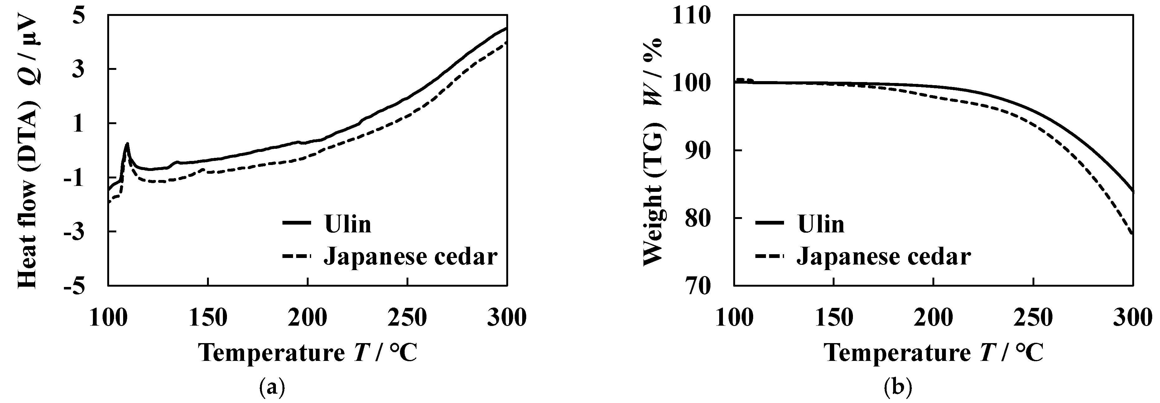
2.2. Differential Thermal Analysis and Thermogravimetry
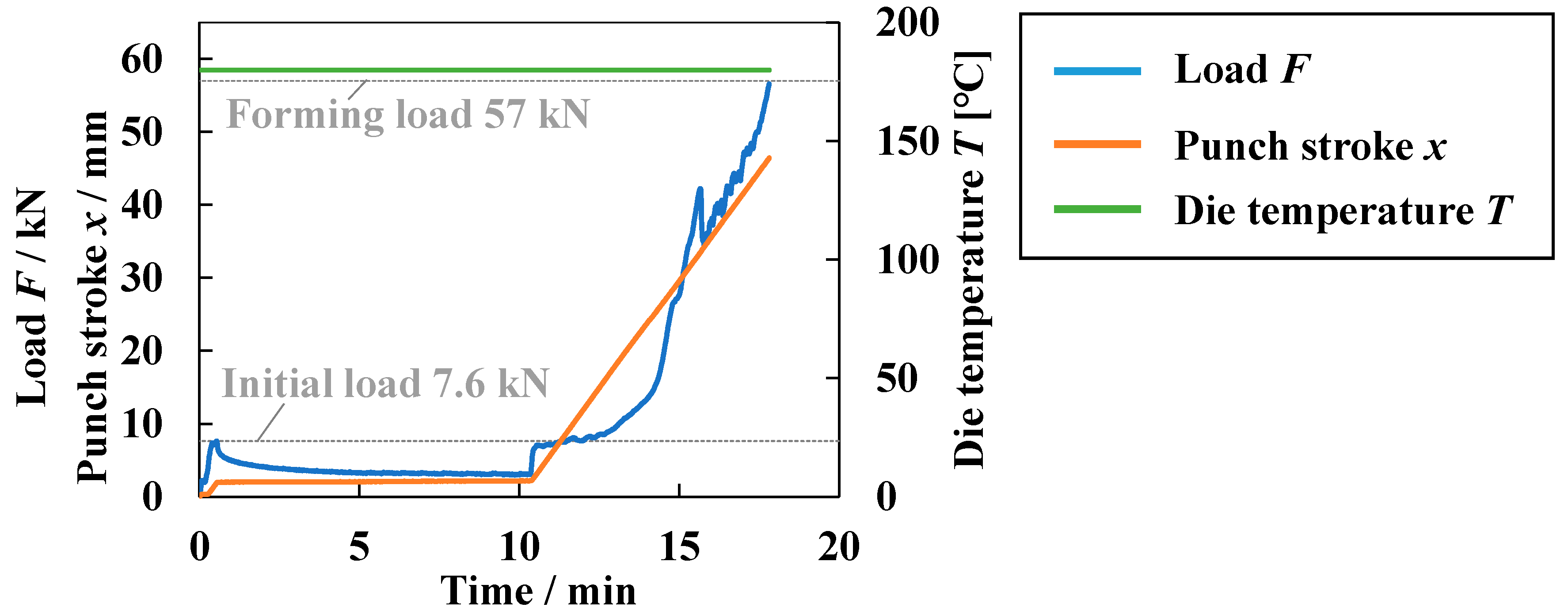
DTA and TG of ulin and Japanese cedar were carried out. A differential thermogravimetric analyzer (TG8120), produced by Rigaku Corporation, was used. In the analysis, powder was used as the sample for the analysis. The powder was obtained by cutting the specimen with a band saw. The powder was placed in an aluminum pan, and aluminum oxide was used as a reference. The sample and the reference were heated under a nitrogen atmosphere in the analysis. First, the temperature was increased at a constant rate of 5 °C/min and was held at 105 °C for 30 min to ensure that the moisture conditions of ulin and Japanese cedar were the same. The temperature was then increased to 300 °C at 5 °C/min. Change in heat flow Q and weight ratio W was evaluated. W was calculated by the following equation:
W = m t 1 m t 0 × 100
mt1 is the weight of the sample during the analysis and mt2 is the weight of the sample after drying at 105 °C for 30 min.

2.3. Forging Test

In this experiment, a forging test of cylindrical specimens using a closed die was conducted, and the formability and forming load were evaluated. A CNC press machine, which can control displacement, was used to perform the forging process. Figure 2 shows a schematic cross-section of the die for forging. The cylindrical container is formed by pressing the specimen with the punch in this die. The inner diameter of the die was 30 mm, which was equal to the outer diameter of the specimen. The punch diameter was 22 mm. Table 1 shows the experimental conditions. Three types of punches were used. To check the flowability of the material, the maximum punch length l was set at 65 mm and two types were used to compress the central and side walls, l = 20 mm and 40 mm. The values of initial load Fi and forming load Ff were determined from previous studies [23]. The punch load was measured with a load cell (KCM—1MNA, Tokyo Measuring Instruments Lab., Tokyo, Japan), and punch stroke was measured with a displacement transducer (DT-100A, Kyowa Electronic Instruments Co., Ltd., Tokyo, Japan). The die temperature was controlled using thermocouples and band heaters.
An example of variations in the load F, punch stroke x, and temperature T during the forging process is shown in Figure 3. First, the die was heated using a band heater until it reached the target temperature T, and then the specimen was inserted into the die. The punch was pressed in at a constant rate of 0.1 mm/s. The punch motion was stopped when the F reached the initial load of Fi. Then, the specimen was heated under high-pressure conditions by leaving it for 10 min. This heating time was defined with reference to previous studies [26]. The punch was then pressed in until the limit load reached forming load Ff during forging, after which the punch motion was again stopped. After the punch stopped, heating was also stopped, and the die was air-cooled without unloading. When T fell below 80 °C, the punch was unloaded, and the product was removed.
In a previous study on forging, the formability was significantly changed by the temperature because flow deformation occurs with softening and decomposition of wood components [23]. Therefore, the influence of the temperature on the formability was investigated at first to clarify the temperature at which flow deformation occurs by using the punch of which length l was 65 mm. Die temperatures were set at 160 to 200 °C, based on the appropriate temperatures in existing studies on the flowability of Japanese cedar [12]. In addition, the influence of the punch length l was investigated to determine the depth of containers that can be formed under the proper temperature. The number of trials was one for all experiments.

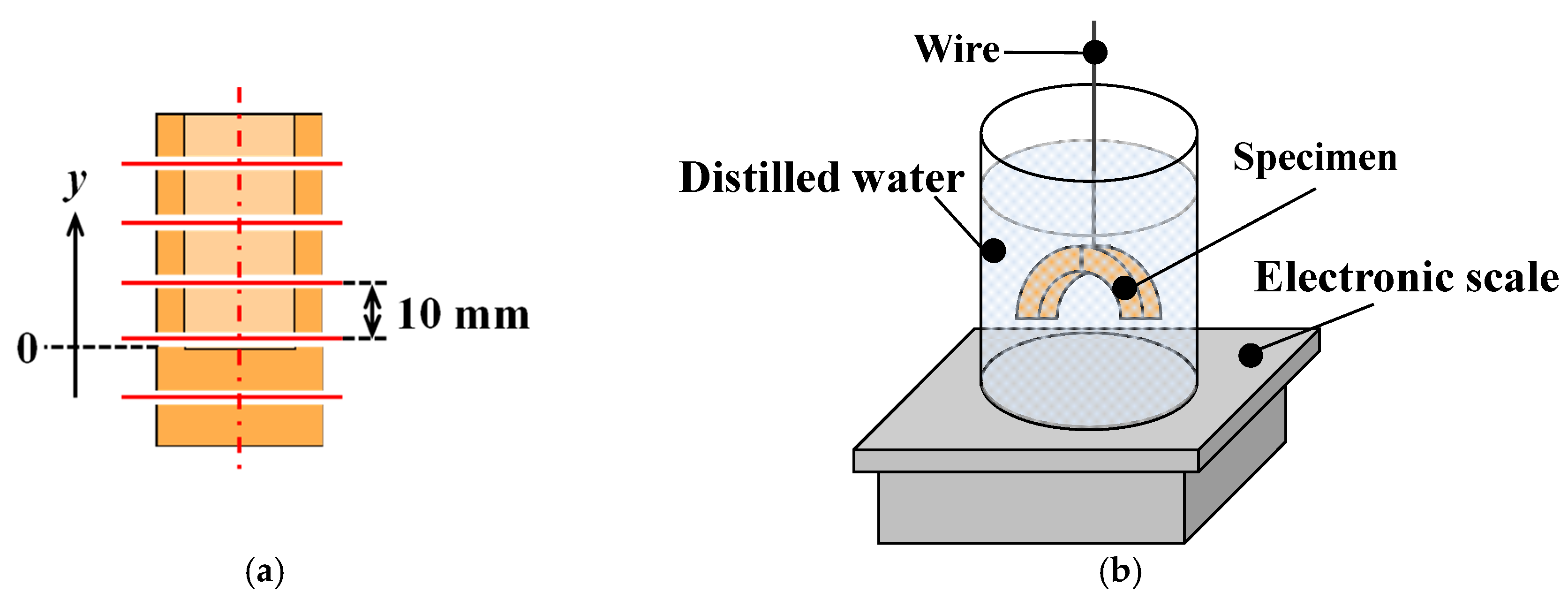
2.4. Evaluation of Formed Products

To evaluate the formability, observations, dimensions, and density measurements were conducted for the formed containers. Appearances and the cross-sections of the formed container were observed. For cross-sectional observation, a microscope (VHX-900F, KEYENCE, Osaka, Japan) was used if required. The container height hc and the wall height hw, which are shown in Figure 3, were measured by using a caliper. The density ρ distribution in the height direction of the container was investigated to evaluate the uniformity of the container. The container was sliced in 10 mm increments, as shown in Figure 4a, and ρ of each piece was measured. The height position from the container bottom was defined as y. ρ was determined by measuring the mass and the volume of each piece. The volume was measured using Archimedes’ principle according to Japanese Industrial Standard JIS Z 8807 [27]. This volumetric method uses the fact that the buoyancy of the water is balanced by the volume of the object being measured. Specifically, the object is placed inside a beaker filled with distilled water, and the increase in mass before and after the placement is taken as the volume of the object. The Archimedes’ principle does not hold if the object touches the beaker, so a wire is used to suspend the object from the beaker, as shown Figure 4b. The number of trials is two for each condition.

3. Results and Discussion

3.1. Heat Flow and Weight Change during Temperature Increasing

Figure 5 shows the change in the heat flow Q and the weight ratio W. As shown in Figure 5a, there was an exothermic reaction at about 105 °C due to drying. Except for this exothermic reaction, there was no significant exothermic or endothermic reaction, and the difference in Q between ulin and Japanese cedar was not observed. W decreased from about 160 °C for each material as shown in Figure 5b. It is considered that this weight reduction occurred as any components volatilized with any chemical changes. This chemical change was suggested to possibly affect the flowability of the wood in the previous study [28]. The difference in W between ulin and Japanese cedar was also small. From the result of the thermal analysis, the difference in the chemical change with heating between ulin and Japanese cedar is small.

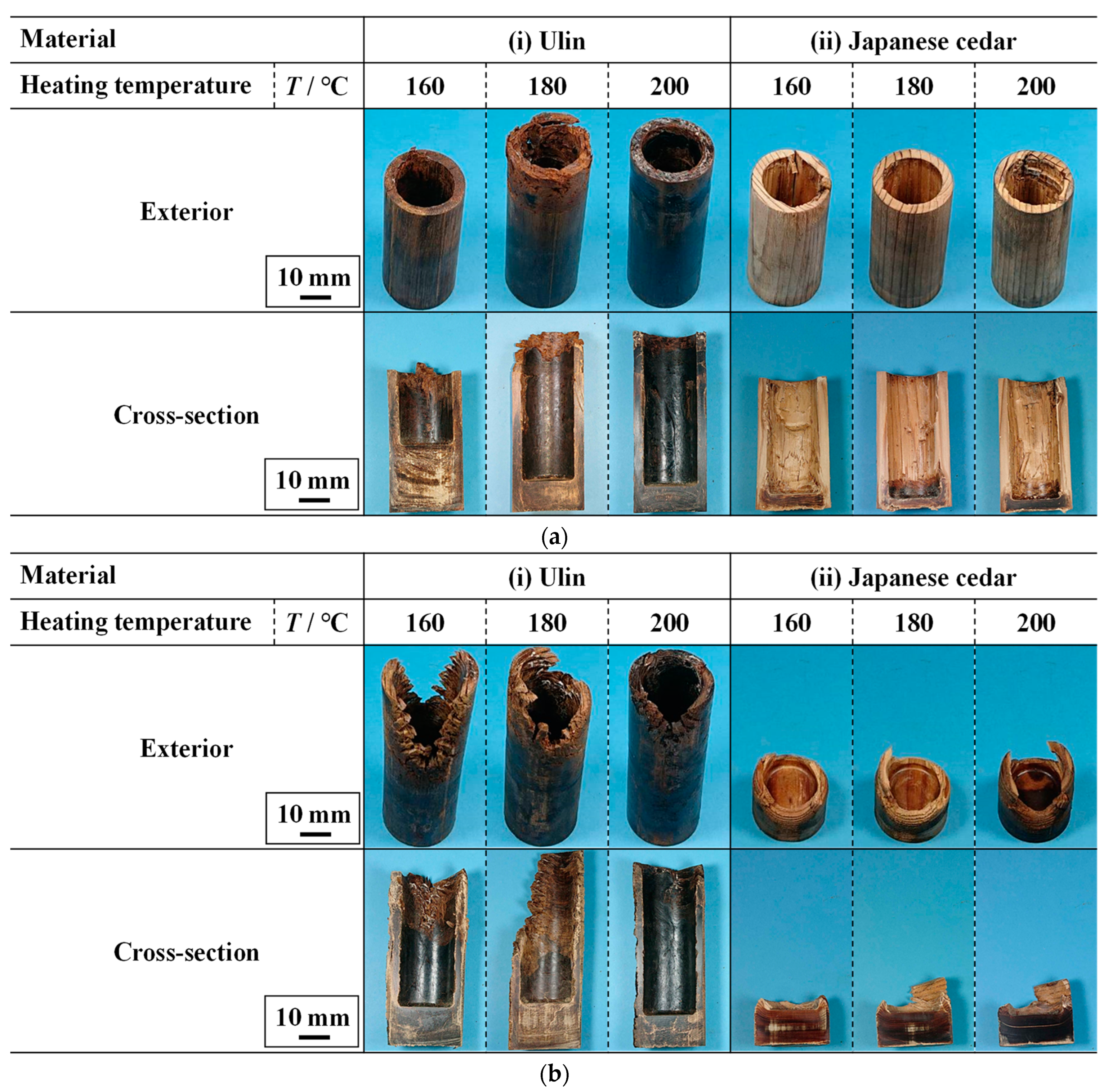
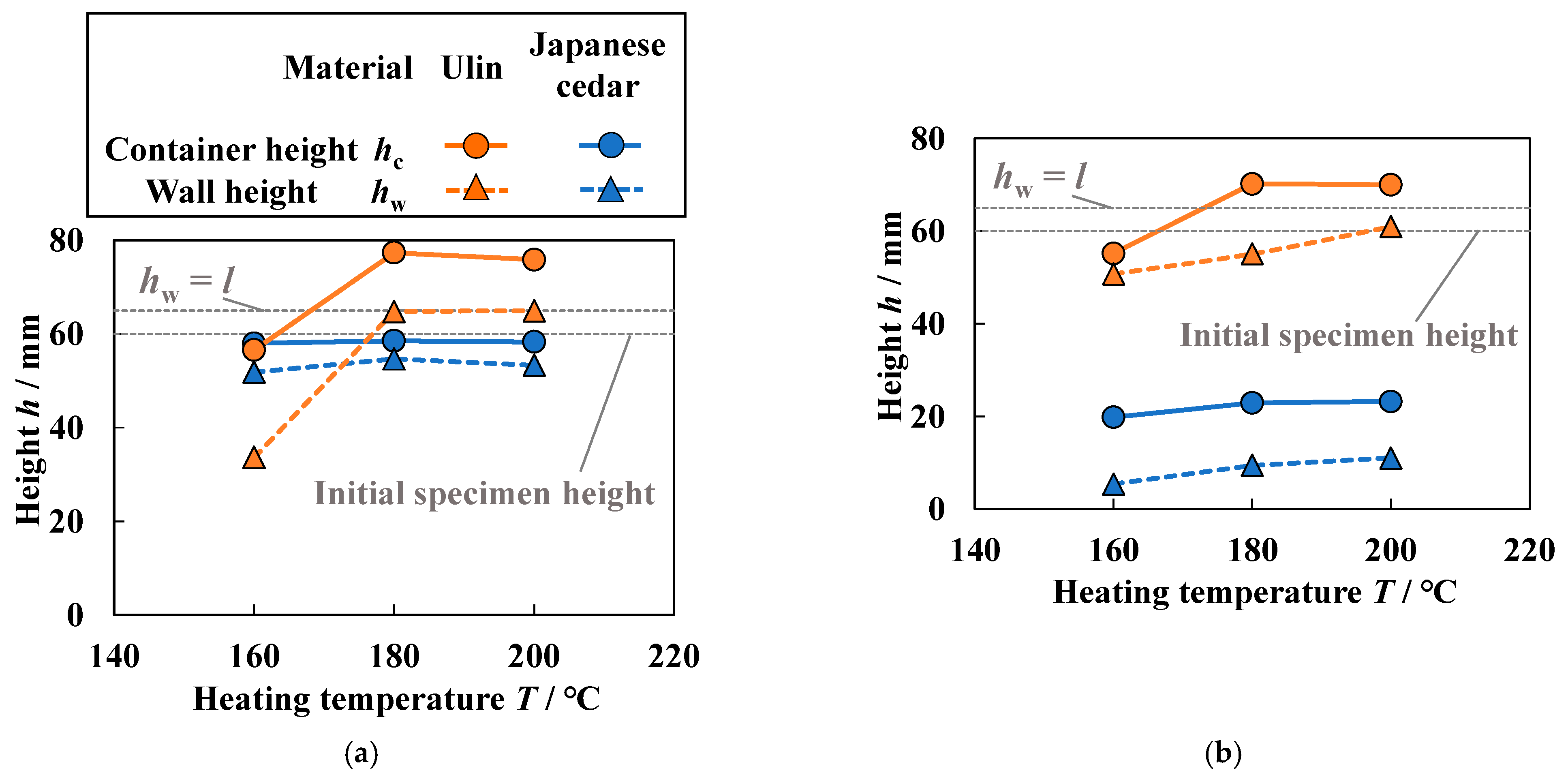
3.2. Effect of Temperature on Formability

Experiments were conducted at three heating temperatures of T = 160, 180, and 200 °C. The punch length l was 65 mm. Figure 6 shows the appearance of the formed product and the cross-section of the product. In the case of the L-directional pressing as shown in Figure 6a, a container shape was formed for each material. In contrast, in the case of R-directional pressing as shown in Figure 6b, the shape differed greatly depending on the material. A container-shaped product was obtained, but cracks were more likely to appear in the wall when ulin was used as shown in Figure 6b(i). The cracks in the walls tended to improve with increasing T. In the case of Japanese cedar as shown in Figure 6b(ii), the entire specimen was compressed and the walls were hardly formed at all, and no effect of temperature was observed.
Figure 7a shows the effect of the heating temperature T on the container height hc and the wall height hw of the formed product for the L-directional pressing. hc was higher than the initial specimen height under the conditions of T = 180 and 200 °C when ulin was used. In these conditions, hw became the same as the punch length l. This means that the material at the bottom portion flowed to the side wall and then into the die. At T = 160 °C, h was almost the same as the initial specimen height and hw was lower than l. At this temperature, only the center part was compressed, and the material did not flow to the side walls. When Japanese cedar was used, T had no significant effect on hc and hw. The material did not flow into the die, as hw was shorter than l, and hc was almost unchanged from the specimen’s initial height. It is considered that the difference in deformation between wood species is attributed to differences in chemical changes with the heating or microstructure of the material. The differences in chemical changes between ulin and Japanese cedar might be small with reference to the result of the thermal analysis as shown in Figure 5. Therefore, the difference in deformation behavior between ulin and Japanese cedar might be attributed to differences in density with the microstructure of the materials.
Figure 7b shows the effect of the heating temperature T on the container height hc and the wall height hw of the formed product for the R-directional pressing. When ulin was used, hw increased with increasing T, but hw was shorter than the punch length at each T. It is considered that hw increased with increasing T because the softening and the decomposition reaction of the constituent components of wood due to heating improves its fluidity [11]. This is due to the thermo-softening of hemicellulose and lignin. According to a previous study [29], hemicellulose is a polysaccharide with a dry thermo-softening temperature of 167 to 217 °C. In particular, the flow of wood-based materials is affected by the hydrolysis of hemicellulose in addition to the softening of lignin. At 160 to 200 °C, the hydrolysis of hemicellulose is more active at higher temperatures, and the decomposition produces low molecular weight sugars [28]. In this temperature range, the sugars are fluid, which is thought to facilitate the generation of flow deformation, such as sliding between the fibers. When Japanese cedar was used, hc and hw were very low, and the effect of T was not seen. From these results, the effect of temperature was stronger for ulin than for Japanese cedar.
Figure 8 shows the load F variations with the punch stroke x during the forging process when the temperature was 200 °C. The behavior of the load F varied depending on the pressing direction and the material. To investigate the deformation during the process, specimens were removed and observed when the punch stroke x was 20 and 40 mm during forging. Figure 9 shows the change in the shape of the specimen during the process when the temperature T was 200 °C. From Figure 8 and Figure 9, the differences in the deformation due to the pressing direction and the material are discussed.
In the case of pressing in the L direction, only the center of the specimen, which contacts the punch, was compressed, while the edge area was not compressed because the fiber slips between the center and edge area regardless of the material as shown in Figure 9a. As shown in Figure 8a, the load F drastically increased with the punch stroke x at first, but the change in F became small after F reached about 5 kN. It is considered that buckling of the fibers occurred when F reached about 5 kN, and then the material was compressed, while the voids within the material were crushed. When the void size within the material became small, F increased again for each material, but x of which F increased again was different by the material. As for Japanese cedar, F increased again when x was about 45 mm, and reached the limit load without flow deformation. Therefore, the container shape was obtained by crushing the voids in the center of the specimen as shown in Figure 9a(ii). As for ulin, F increased again when x was about 20 mm as shown in Figure 8a. This is because the void volume inside ulin is small. Then, F decreased when x was between 30 and 40 mm, which signals the occurrence of flow deformation [17]. The starting point of the decrease in F is called the yield point in this paper. F increased again when the material was filled in the die by flow deformation, and F reached the limit load. For this reason, the wall height hw of the ulin cup was higher than that of the Japanese cedar cup when the specimen was pressed in the L direction.
When pressing was performed in the R direction, which is the direction perpendicular to the fibers, the center portion of the specimen was compressed along with the edge portion regardless of the material, as shown in Figure 8b, because the fibers were not cut at the boundary between the center and edge portion. As shown in Figure 8b, the load F gradually increased in the early stage of forging because the fiber did not buckle and void crushing began immediately. As for Japanese cedar, F increased drastically when the punch stroke x was about 40 mm and reached the limit load without flow deformation. This behavior is similar to that in the L direction, and it is considered that F increased drastically when the void volume within the material became small. Therefore, the specimen was compressed without forming the side wall as shown in Figure 9b(ii). As for ulin, the increase in F became rapid when x was about 10 mm, and then F increased and decreased repeatedly with two yield points as shown in Figure 8b. It is considered that flow deformation occurred with intermittent void crushing. F increased drastically when x was about 40 mm, and reached the limit load as the material reached the top of the die.
Flow deformation was possible for both compression directions when ulin was used, although flow deformation did not occur with Japanese cedar. As shown in Figure 9, cracks appeared at the bottom portion during the pressing of ulin, while cracks were not observed in the case of Japanese cedar. It is considered that flow deformation easily occurs in ulin because the fibers are slippery in the cracks. Figure 10 shows micrographs of the initial specimen during forging and when ulin was used for L- and R-directional pressing. Wood fibers, vessels, parenchyma cells, and rays were observed in the specimen before pressing as shown in Figure 10c. The parenchyma cells are continuously distributed in the T direction, and rays are continuously distributed in the R direction. Wood fiber has few voids, while vessels have many voids. Therefore, the vessels were not observed in the product during forging because the vessels were compressed as shown in Figure 10d. The cracks were seen at the layers of the parenchyma cells and the rays. This is considered to be because the parenchyma cells and the rays are softer than wood fiber. The flow deformation could have been caused by slipping in the parenchyma cells and rays. Figure 11 shows microscope photographs of the product during forging and specimen before pressing when Japanese cedar was used. The structure of Japanese cedar is simpler than that of ulin. Earlywood and latewood, which are composed of tracheid, were observed in the specimen before pressing. Buckling of fibers was observed in the product of L-directional pressing and reduction in intracellular porosity inside the tracheid was observed in the product of R-directional pressing. On the other hand, the number of cracks was small. Therefore, it was considered that the flow deformation was difficult in the case of Japanese cedar.
In previous studies, flow deformation of Japanese cedar was possible, but the material needed to be in a high moisture state or impregnated with resin to increase its fluidity [22]. However, the results of the present study show that ulin exhibited flowability and produced a formed product with a large wall height using a processing method without resin impregnation, which was not possible with Japanese cedar. Ulin has an advantage over Japanese cedar in that it can flow deform even in an air-dry state and without resin.

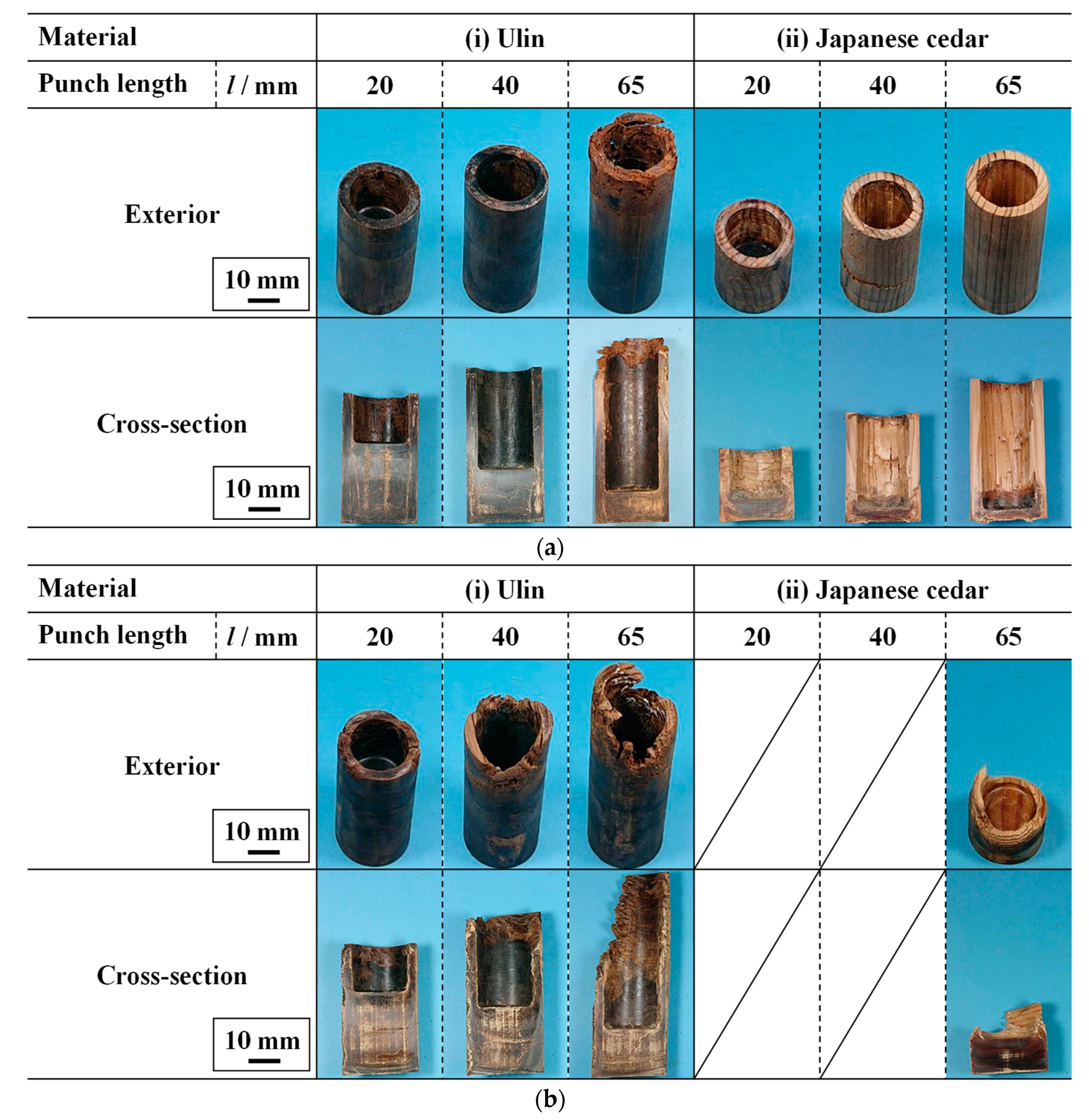
3.3. Effect of Punch Length on Formability

To investigate the conditions for forming a container without defects, the effect of punch length l on formability was investigated. The container temperature T was set to 180 °C in this investigation. The relationship between l and the appearance of the formed product is shown in Figure 12. The products without cracks were obtained under the appropriate conditions. In the case of L-directional pressing of ulin, as shown in Figure 12a(i), the product was successfully formed when l was 20 and 40 mm, but the crack was observed at the top of the side wall when l was 65 mm. In the case of L-directional pressing of Japanese cedar, as shown in Figure 12a(ii), some cracks appeared on the side wall due to the fiber buckling. In the case of R-directional pressing of ulin, as shown in Figure 12b(i), the product was successfully formed when l was 20 mm, but the crack was observed at the top of the side wall when l was 40 and 65 mm. In the case of R-directional pressing of Japanese cedar, as shown in Figure 12b(ii), the side wall was not formed under the condition of l = 65 mm, so the experiments using the punch of l = 20 and 40 mm were not conducted.
Figure 13 shows the effect of the punch length l on the container height hc and the wall height hw for the formed product. As shown in Figure 13a, hw and l for ulin matched under all conditions when the specimen was pressed in the L direction, which means that the material flowed into the die. However, Japanese cedar did not flow into the die in the case of l = 65 mm, while it flowed into the die in the cases of l = 20 and 40 mm. As shown in Figure 13b for R-directional pressing, the ulin flowed into the die only at l = 20 mm. In the case of l = 40 mm with ulin, the material did not flow into the die, although hw was larger than 40 mm under the condition that l was 65 mm. It is considered that this is because the tip of the flowing material was subjected to a reaction force from the punch surface when it reached the top of the die, and then the material was not filled at the top portion.
Figure 14 shows the distribution of the density ρ in the height direction. Here, portions with large cracks were not measured because they are difficult to measure. In the case of ulin, ρ was similar to the density of the material for larger values of y in the wall. ρ ranged at 1.12 to 1.42 g/cm3, which was greater in most parts than that of the original ulin. The compression of vessels is considered to have increased ρ. In particular, at punch lengths l = 20 mm and 40 mm, ρ ranged from 1.26 to 1.38 g/cm3 in the L-directional pressing. In the case of R-directional pressing, ρ ranged from 1.33 to 1.40 g/cm3 at punch length l = 20 mm. Therefore, the density became almost uniform by using the punch with the appropriate length. The above results show that the forging process produces a product with a higher density and uniformity of ulin than the cutting process. For Japanese cedar, ρ differed greatly between the bottom and the side wall. Especially at the bottom, the density of Japanese cedar was similar to that of ulin. In general, the density of well-compacted wood is constant regardless of the material. In other words, this result suggests that at the bottom, the Japanese cedar porosity is almost completely eliminated by the compression [22]. At the side wall, ρ decreased with the increase in height position y, and was almost the same as that of the original Japanese cedar. This is because the center portion was mainly compressed without flow deformation when the material was pressed in the L direction.
Based on the above results, the appropriate forming conditions were considered. When ulin was used, a container with uniform and high density was formed in the case of both L and R direction compression, and the maximum wall height hw without any defects was 40 mm when the compression direction was L. When Japanese cedar was used, it was difficult to form a container with uniform and high density, because Japanese cedar must contain a high moisture level or be impregnated with synthetic resin. However, a sealed die with a valve for releasing water vapor needs to be used for forming wood with high moisture content. In addition, the use of synthetic resin has negative effects on the environment. Thus, ulin could be appropriate for forming environmentally friendly products by forging. This study has shown the possibility that various shaped products with high strength and decay resistance could be produced by forging ulin.

4. Conclusions

Cylindrical containers were fabricated from ulin by forging using a closed die to investigate the formability of high-density wood. The effects of die temperature and punch length on formability were investigated by using ulin, a high-density wood, and Japanese cedar, a commonly used wood, in an air-dried state. The following findings were obtained: Ulin flows more easily than Japanese cedar. With ulin, it was possible to produce a deep container with a high and uniform density as flow deformation occurred regardless of the direction of compression. Ulin became flowable when the temperature was 180 to 200 °C, and the maximum wall height without any defects was 40 mm. The density of the container ranged from 1.3 to 1.5 g/cm3. In contrast, Japanese cedar was less flowable and could not be formed into a container with uniform density. When Japanese cedar was forged, only the bottom was densified in the case of L-directional pressing, and the entire material was compressed without forming a side wall in the case of R-directional pressing. The difference in deformation behavior between ulin and Japanese cedar was considered to be attributed to differences in density with the microstructure of the materials because the difference in the chemical change with heating was small based on the result of the thermal analysis. The results indicate that forging is suitable for shaping ulin and that products with various shapes can be produced. Through this research, it was suggested that ulin could be forged to produce a variety of shapes with hardness and decay resistance.

Author Contributions

Conceptualization, H.U., T.K., S.T. and S.K.; methodology, H.U., T.K., S.T. and S.K.; software, T.K. and S.K.; validation, H.U.; formal analysis, H.U. and S.K.; investigation, H.U. and S.K.; resources, H.U., T.K., and S.K.; data curation, H.U. and S.K.; writing—original draft preparation, H.U.; writing—review and editing, H.U., T.K., S.T. and S.K.; visualization, H.U.; supervision, S.K.; project administration, H.U. and S.K.; funding acquisition, S.T. and S.K. All authors have read and agreed to the published version of the manuscript.

Funding

This work was supported by the Japan Society for the Promotion of Science under KAKENHI grant number 22K04773.

Data Availability Statement

Data are contained within the article.

Acknowledgments

The authors would like to thank J. Hayashida, Inc. for providing ulin.

Conflicts of Interest

The funders had no role in the design of the study; in the collection, analyses, or interpretation of data; in the writing of the manuscript; or in the decision to publish the results.

References

  1. Astrup, T.; Fruergaard, T.; Christensen, T.H. Recycling of plastic: Accounting of greenhouse gases and global warming contributions. Waste Manag. Res. 2009, 27, 763–772. [Google Scholar] [CrossRef]
  2. Geyer, R.; Jambeck, J.R.; Law, K.L. Production, use, and fate of all plastics ever made. Sci. Adv. 2017, 3, e1700782. [Google Scholar] [CrossRef]
  3. Wang, M.; Bauer, F.; Syberg, K.; Gammage, T. Finance plastics reuse, redesign, and reduction. Science 2023, 382, 526. [Google Scholar] [CrossRef]
  4. Shen, M.; Huang, W.; Chen, M.; Song, B.; Zeng, G.; Zhang, Y. (Micro)plastic crisis: Un-ignorable contribution to global greenhouse gas emissions and climate change. J. Clean. Prod. 2020, 254, 120138. [Google Scholar] [CrossRef]
  5. Umemura, K. Introduction of research on sustainable and environmentally friendly wood-based materials. Impact 2020, 2020, 73–75. [Google Scholar] [CrossRef]
  6. Yang, S.; Choi, G.; Kim, J.; Lee, H.; Kang, S. Comparison of Mechanical Properties According to the Structural Materials of Lumber, GLT, CLT, and Ply-lam CLT. Bio Resour. 2023, 18, 6971–6985. [Google Scholar] [CrossRef]
  7. Eder, A. Global Trends in Wood-Plastics Composites (WPC). Bioplastics Mag. 2016, 8, 16–17. [Google Scholar]
  8. Wolcott, W.P. Wood-Plastic Composites. In Encyclopedia of Materials: Science and Technology; Elsevier: Amsterdam, The Netherlands, 2001; pp. 9759–9763. [Google Scholar]
  9. Tao, X.; Nonaka, H. Wet Extrusion Molding of Wood Powder with Hydroxy-propylmethyl Cellulose and with Citric Acid as a Crosslinking Agent. Bio Resour. 2021, 16, 2314–2325. [Google Scholar] [CrossRef]
  10. Abe, M.; Seki, M.; Miki, T.; Nishida, M. Rapid Benzylation of Wood Powder without Heating. Polymers 2021, 13, 1118. [Google Scholar] [CrossRef] [PubMed]
  11. Takahashi, I.; Takasu, Y.; Sugimoto, T.; Kikata, Y.; Sasaki, Y. Thermoplastic flow behavior of steamed wood flour under heat and compression. Wood Sci. Technol. 2010, 44, 607–619. [Google Scholar] [CrossRef]
  12. Takahashi, I.; Sugimoto, T.; Takasu, Y.; Yamasaki, M.; Sasaki, Y.; Kikata, Y. Effect of wood species on thermal flow behavior and physical properties of thermoplastic molding. Wood Sci. Technol. 2012, 46, 419–429. [Google Scholar] [CrossRef]
  13. Mudianta, W.; Artha, N.G.S.; Muderawas, W.; Martiningsih, N.W. Chemical profile and antibacterial activity of essential oil from ironwood (Eusideroxylon zwageri) sawdust. Food Sci. Technol. 2023, 9, 2202033. [Google Scholar] [CrossRef]
  14. Inoue, M.; Norimoto, M.; Tanahashi, M.; Rowell, R.M. Team or Heat Fixation of Compressed Wood. Wood Fiber Sci. 1993, 25, 224–235. [Google Scholar]
  15. Kutnar, A.; Sandberg, D.; Haller, P. Compressed and moulded wood from processing to products. Holzforschung 2015, 69, 885–897. [Google Scholar] [CrossRef]
  16. Sandberg, D.; Haller, P.; Navi, P. Thermo-hydro and thermo-hydro-mechanical wood processing: An opportunity for future environmentally friendly wood products. Wood Mater. Sci. Eng. 2003, 8, 64–88. [Google Scholar] [CrossRef]
  17. Miki, T.; Sugimoto, H.; Shigematsu, I.; Kanayama, K. Superplastic deformation of solid wood by slipping cells at sub-micrometer intercellular layers. Int. J. Nanotechnol. 2014, 11, 509–519. [Google Scholar] [CrossRef]
  18. Abe, M.; Seki, M.; Miki, T.; Nishida, M. Effect of the Propionylation Method on the Deformability under Thermal Pressure of Block-Shaped Wood. Molecules 2021, 26, 3539. [Google Scholar] [CrossRef] [PubMed]
  19. Abe, M.; Enomoto, Y.; Seki, M.; Miki, T. Esterification of Solid Wood for Plastic Forming. Bio Resour. 2020, 15, 6282–6298. [Google Scholar] [CrossRef]
  20. Seki, M.; Yashima, Y.; Abe, M.; Miki, T.; Nishida, M. Influence of delignification on plastic flow deformation of wood. Cellulose 2022, 29, 4153–4165. [Google Scholar] [CrossRef]
  21. Yamashita, O.; Imanishi, H.; Kanayama, K. Transfer molding of bamboo. J. Mater. Process. Technol. 2007, 192–193, 259–264. [Google Scholar] [CrossRef]
  22. Kajikawa, S.; Iizuka, T.; Yamaishi, K.; Takakura, N. Small Container Fabrication Using Closed Die Wood Forging. Steel Res. Int. 2011, 2011, 229–234. [Google Scholar]
  23. Kajikawa, S.; Iizuka, T.; Yamaishi, K. Displacement Behavior of Wood in Boss Forming Using Open-Die Wood Forging. Key Eng. Mater. 2012, 504–506, 1261–1266. [Google Scholar] [CrossRef]
  24. Aiso-Sanada, H.; Nezu, I.; Ishiguri, F.; Jaffar, A.N.N.B.M.; Ambun, D.B.A.; Perumal, M.; Wasli, M.E.; Ohkubo, T.; Abe, H. Basic wood properties of Borneo ironwood (Eusideroxylon zwageri) planted in Sarawak, Malaysia. Tropics 2020, 28, 99–103. [Google Scholar] [CrossRef]
  25. JIS Z 2101; Methods of Test for Woods. Japanese Standards Association: Tokyo, Japan, 2009.
  26. Kajikawa, S.; Iizuka, T. Hot press moldability of bamboo powder without additives. Key Eng. Mater. 2014, 611–612, 852–858. [Google Scholar] [CrossRef]
  27. JIS Z 8807; Methods of Measuring Density and Specific Gravity of Solid. Japanese Standards Association: Tokyo, Japan, 2012.
  28. Kajikawa, S.; Iizuka, T. Effect of Water-soluble Components Mass on the Fluidity of the Steam treated Bamboo Powder Caused by Heating and Compression. J. Soc. Mater. Sci. 2015, 64, 381–386. [Google Scholar] [CrossRef]
  29. Ramiah, M.V.; Goring, D.A.I. The thermal expansion of cellulose, hemicellulose, and lignin. J. Polym. Sci. Part C Polym. Symp. 1965, 11, 27–48. [Google Scholar] [CrossRef]
Figure 1. Definition of direction and appearance of specimens. (a) Classification of wood fiber directions. (b) Images of specimens.
Jmmp 08 00030 g001
Figure 2. Schematic cross-section of forging die.
Jmmp 08 00030 g002
Figure 3. Experimental parameter variations during forging (load, stroke, and temperature) (ulin, L-directional pressing, T = 200 °C, l = 65 mm).
Jmmp 08 00030 g003
Figure 4. Density measurement method. (a) Cutting position of the specimen. (b) Volume measurement using Archimedes’ principle.
Jmmp 08 00030 g004
Figure 5. Differential thermal analysis and thermogravimetry. (a) DTA. (b) TG.
Jmmp 08 00030 g005
Figure 6. Effect of temperature T on appearance (l = 65 mm). (a) L-directional pressing. (b) R-directional pressing.
Jmmp 08 00030 g006
Figure 7. Effect of compression direction and heating temperature T on container height hc and wall height hw (l = 65 mm). (a) L-directional pressing. (b) R-directional pressing.
Jmmp 08 00030 g007
Figure 8. Load variations during the forming process (T = 200 °C, l = 65 mm). (a) L-directional pressing. (b) R-directional pressing.
Jmmp 08 00030 g008
Figure 9. Changes in appearance of specimens with strokes during forging (T = 200 °C, l = 65 mm). (a) L-directional pressing. (b) R-directional pressing.
Jmmp 08 00030 g009
Figure 10. Micrographs of cross-section before and during forging (ulin, T = 200 °C, l = 65 mm). (a) L-directional pressing, stroke x = 0 mm (specimen). (b) L-directional pressing, x = 20 mm. (c) R-directional pressing, x = 0 mm (specimen). (d) R-directional pressing, x = 20 mm.
Jmmp 08 00030 g010
Figure 11. Micrographs of cross-section before and during forging (Japanese cedar, T = 200 °C, l = 65 mm). (a) L-directional pressing, stroke x = 0 mm (specimen). (b) L-directional pressing, x = 20 mm. (c) R-directional pressing, x = 0 mm (specimen). (d) R-directional pressing, x = 20 mm.
Jmmp 08 00030 g011
Figure 12. Effect of punch length l on appearance (T = 180 °C). (a) L-directional pressing. (b) R-directional pressing.
Jmmp 08 00030 g012
Figure 13. Effect of compression direction and heating temperature T on container height hc and wall height hw (T = 180 °C). (a) L-directional pressing. (b) R-directional pressing.
Jmmp 08 00030 g013
Figure 14. Effect of punch length l on density distribution in height direction (T = 180 °C). (a) Ulin, L-directional pressing. (b) Ulin, R-directional pressing. (c) Japanese cedar, L- and R-directional pressing.
Jmmp 08 00030 g014
Table 1. Experimental conditions for forging test.
Heating temperatureT/°C160
180
200
Punch lengthl/mm20
40
65
Initial loadFi/kN7.6
Forming loadFf/kN57
Moisture contentu/%13
Disclaimer/Publisher’s Note: The statements, opinions and data contained in all publications are solely those of the individual author(s) and contributor(s) and not of MDPI and/or the editor(s). MDPI and/or the editor(s) disclaim responsibility for any injury to people or property resulting from any ideas, methods, instructions or products referred to in the content.

