Article

Numerical Modelling for Efficient Analysis of Large Size Multi-Stage Incremental Sheet Forming

1
Faculty of Engineering, Alexandria University, Alexandria 21544, Egypt
2
Joining and Welding Research Institute, Osaka University, Osaka 567-0047, Ibaraki, Japan
3
Nissan Motor Co., Ltd., Natsushima, Yokosuka 237-8523, Kanagawa, Japan
*
Author to whom correspondence should be addressed.
J. Manuf. Mater. Process. 2024, 8(1), 3; https://doi.org/10.3390/jmmp8010003
Submission received: 16 November 2023 / Revised: 13 December 2023 / Accepted: 16 December 2023 / Published: 22 December 2023
(This article belongs to the Special Issue Advances in Material Forming)

Abstract

:
Incremental sheet forming (ISF) is an advanced flexible manufacturing process to produce complex 3D products. Unlike the conventional stamping process, ISF does not require any high cost dedicated dies. However, numerical computation for large-size ISF processes is time-consuming, and its accuracy for spring back due to unclamping tools after ISF cannot satisfy industrial demand. In this paper, an advanced numerical model considering complicated forming tool paths, trimming, and spring back was developed to efficiently simulate the multi-stage deformation phenomena of incremental sheet forming processes. Numerical modeling accuracy and efficiency are investigated considering the influence of tool path, material properties of the blank, mesh size, and boundary conditions. Through a series of case studies and comparisons with experimental results, it is observed that the numerical model with kinematics material properties and a moderate element size (5 mm) may reproduce the deformation characteristics of ISF with good accuracy and can obtain practical efficiency for a large-size ISF part.

1. Introduction

Incremental sheet forming (ISF) is a technology for forming customized parts, characterized by money-saving and rapid prototyping. This technology is now being applied in the automobile industry by manufacturing thin sheet parts without the assistance of dies and punches. There are many forming processes in industrial applications. One of them is the incremental bending process for complicated curved sheet metal [1]. The blank sheet is bent incrementally, step by step. An incremental bending prototype is designed and manufactured. The most widely used conventional forming process is stamping [2], which has the drawback of high investment costs. As time passes, many vehicles and equipment become scarce, and large-quantity productions are not possible [3]. Our target in this paper is to analyze the deformation behaviors of large-size incremental forming parts with ac-acceptable accuracy and efficiency for industrial applications. The target parts may be automotive parts, ship hull components, airplane fuselages, or others. Kumar et al. [4] addressed incremental sheet forming (ISF) through a series of small incremental deformations using a forming tool and a CAD model. The process simulation is limited to small-size batch production and is time consuming. Ambrogio [5] and A. Gohil et al. [6] investigate the influence of some relevant process parameters on the dimensional accuracy of incremental sheet forming. Many papers have been published on incremental sheet forming, most of which simulate small sizes of sheet plates [7].
Tegan et al. [8] comprised literature reviews on single-point incremental forming and presented parameters that influence the formability accuracy of sheet metals, such as material thickness, wall angle, moving tool shapes, and tool path. Kim and Park [9] investigated experimental and numerical parameters that affect the formability of incremental sheet forming, such as tool size, tool path, friction at the interface between tool and sheet, and the plane anisotropy of the material. It was found that the formability accuracy may be improved when a ball tool of a particular size is used with a small feed rate and a little friction. Kumar et al. [10] carried out quantitative studies to show different process parameters and techniques that affect the forming forces significantly. Although the process mechanics are based on a pure-stretching deformation, some bending zones close to the clamping fixture are not avoidable. Wu et al. [11] applied a universal backing plate (U-backing plate) consisting of fixed-width sub-plates to reduce the bending deviation by positioning sub-plates along any horizontal direction. Numerical and experimental investigations of the fabrication of truncated pyramids were conducted using Al 5052-O aluminum alloy sheets of size equal to 240 × 240 × 0.5 mm. Many factors were examined to eliminate the bending deviation. Also, Wu et al. [12] presented a novel parametric multi-step toolpath that uses one additional step to form a non-axisymmetric component with the Al2024 sheet. Acceptable accuracy of geometry below ± 0.6 mm may be obtained experimentally and numerically by adjusting the influencing factors of the multi-step toolpath. Yamashita et al. [13] investigated different tool paths and different tooling shapes in their research work; however, higher values of material density and tool speed were assumed, which caused a higher inertia force during forming. Some methods of sheet forming are carried out at different temperatures. So, it requires experimental tests that suitably represent the contact phenomena related to temperature and friction properties [14]. A recent study applied a contact-induced vibration tool (V-Tool) with a flat elliptical-shaped tip into the ISF of a 0.5 mm Al5052 sheet. Hyperbola shapes were manufactured by the ISF using the V-Tool. It was found that shear deformation plays a more significant role in obtaining high formability [15]. Additionally, many researchers have attempted to improve formability accuracy by applying different material properties in FEM models with implicit and explicit time integration schemes. Kim and Yang [16] conducted numerical analyses on a blank model with an isotropic elastic-plastic material. The effect of the traveling pattern of the tool and the density of the sheet material were examined. Tamer et al. [17] present a comparison of the numerical models using implicit and explicit approaches, along with validation of experimental results. Only the parameters of the tool shapes are investigated in their work to measure the thickness distribution through the forming section.
After the metal workpiece is formed and the tools are extracted from the workpiece, the elastic deformation will be released, and only the plastic deformation will remain. The release of the elastic deformation creates a different shape than that created using the moving tool [18]. For this reason, a sensible spring back is generally obtained when an incremental forming process is carried out, compromising, for instance, the geometrical accuracy and a deviation of accurate shapes [19,20]. Many researchers have considered the effect of kinematic hardening material when modeling the blank to improve the formability accuracy by applying, for example, Yoshida-Uemori parameters [21,22,23]. Xia et al. [24] adopted a procedure consisting of variations of the particle swarm optimization (PSO) method to acquire the Yoshida-Uemori (Y-U) hardening model parameters. The formability of the shape is improved because of the improved fitting accuracy of the Y-U hardening mode. In addition, much of the literature has considered and investigated other types of materials when applying incremental sheet forming, such as high-strength and composite materials [25,26].
In incremental sheet forming, the forming simulation is very slow and more time-consuming than the traditional forming simulations. Ulla et al. [27] applied the approach of multi-tooling to minimize the simulation time by utilizing the Abaqus software. Markus [28] applied an adaptive remeshing strategy based on a multi-mesh method for incremental sheet forming simulation. Despite the method reducing the computational time, however, the application was limited to small-size models and ignored many design parameters that have a significant effect on the accuracy of the forming shape. Usually, the adaptivity technique [29] is based on tool curvature or deformation gradients; only the elements close to the tool can be refined. In ISF, the tool is very small, and only a small region of blank can be refined. As a result, much more frequent mesh adaptivity cycles are needed, which will also decrease the computation time [30].
In this paper, a series of FEM analyses, using LSDYNA software [31], is applied to a large-size plate to simulate the forming, releasing the clamps, and trimming flange processes. The phenomenon of spring back is simulated after each forming stage. Large models can capture intricate details of the forming process, resulting in more precise outcomes. Using a large model for ISF can help minimize the need for physical prototypes and experimental trials. Controlling factors such as tool path (tool feed rate, step size), blank element size, material properties, and boundary conditions are explored to examine the influence of these factors on numerical modeling accuracy and efficiency. Comparing the numerical results with experimental ones shows that the developed FEM modeling had good accuracy and practical efficiency for large-size ISF.

2. Experimental Data and Model of ISF

A CNC (Computer Numerical Control) machine (with a tool of 20 mm diameter and 100 mm) height is used to form a large plate of dimension 900 × 740 × 0.7 mm. The plate is made of mild steel (equivalent to A 653 M-DS-DS in ASTM) with a modulus of elasticity of 2.05 × 10⁵ MPa and a density of 7.80 × 10⁻⁹ (ton/mm3). The tool is made of tungsten carbide with a diamond coating on the tip, while the base is made of stainless steel.
The elements layout of the experiment, which composes the base, template, blank sheet, and blank holder, are shown in Figure 1. The template plate serves as a reference or template for the incremental deformation process, while the blank holder is used to hold and control the movement of the sheet metal during the process.
The direction of the moving tool changes with each tool’s path. According to a target model, the maximum forming depth is 70 mm. The traveling speed of the tool is 66.67 mm/s. This speed represents the design speed for this experimental model. The forming process is performed at room temperature without any lubricant material.
Real tool paths during the experiment in X, Y, and Z are shown in Figure 2.
The experimental (measured) model after forming, releasing the clamps, and trimming flanges are presented as shown in Figure 3.
The plate thickness after forming is drastically reduced around the forming area. Samples of the measured thicknesses for the experimental model in the forming area along the X and Y directions are shown in Figure 4.

3. Description of the FEM Model

To investigate the forming accuracy and practical efficiency of the ISF modeling, many numerical simulations are carried out. A large-size plate of 900 × 740 × 0.7 mm is modeled using a quadrature shell element, as shown in Figure 5. The rigid tool of 20 mm diameter and 100 mm height is simulated with a fine mesh of element size equal to 2.5 mm. An automatic free contact surface between the blank and template plate with a gap equal to 0.1 mm is adopted while forming contact with the blank, and the tool is considered. A proper value of the friction coefficient equal to 0.1 is adopted in the simulation model [11]. The tool paths applied in the simulation are schematically shown in Figure 6. According to a target model, the maximum forming depth of 70 mm requires a total path number equal to 350.

4. Parameters Influencing Numerical Modeling Accuracy and Efficiency

The incremental sheet forming process suffers from several drawbacks, such as an inaccurate forming shape compared with the target shape and consuming computational time. Different controlling parameters, though representing a major role in decreasing these drawbacks, are considered through FEM modeling. These are mainly the tool feed rate, the material properties, boundary conditions, and the blank element size.
  • Tool feed rate in FEM modeling
The toolpath used in the ISF process represents the equivalent of a machining operation. In this research work, the real feed rate of the tool when it moves over the sheet is Vr = 66.66 mm/s. The moving tool rotates clockwise and anti-clockwise in each tool path, as shown in Figure 7. The step size means how far the tool presses into the sheet (900 × 740 × 0.7 mm), with each path being 0.3 mm. A series of analyses are carried out to determine the optimum tool feed rate and the mass scaling factor when conducting the forming simulation. Different feed rates are investigated during the forming simulation, such as V = 100 Vr, 500 Vr, and 1000 Vr, respectively, to acquire good formability and optimize the computational time. When assuming a tool feed rate equal to 100 Vr and a mass scaling factor equal to 1, more computational time is consumed; nevertheless, the size of the element. As applied, a mass scaling factor equals 10, and an unacceptable forming shape is noticed. It was concluded from this analysis that the optimum values of the tool feed rate and the mass scaling factor, which predict an acceptable forming shape and less CPU are 500 Vr and 1, respectively.
  • Boundary conditions
To represent the real condition of the experimental model, two different boundary conditions are assumed in FEM analyses. Firstly, the blank is not deformed in the region of the contact area between the blank and the template plate. All elements in this region are assumed to be constrained by the translation and rotation movements.
Secondly, only the edge elements of the blank, where the clamps exist, are constrained from the movements, and allow automatic surface contact in the area between the blank and template plate. These two boundary conditions are illustrated in Figure 8.
  • The blank element size.
The blank is uniformly discretized into quadrilateral elements with different sizes ranging from 2.5 to 5 mm to achieve an accurate forming shape and optimize the computational time. A coarse element mesh of size equal to 10 mm is applied out of the forming area, while a fine element mesh of size 2.5, 3, or 5 mm is applied into the forming area. Figure 9 shows different FEM models furnished with different element sizes.
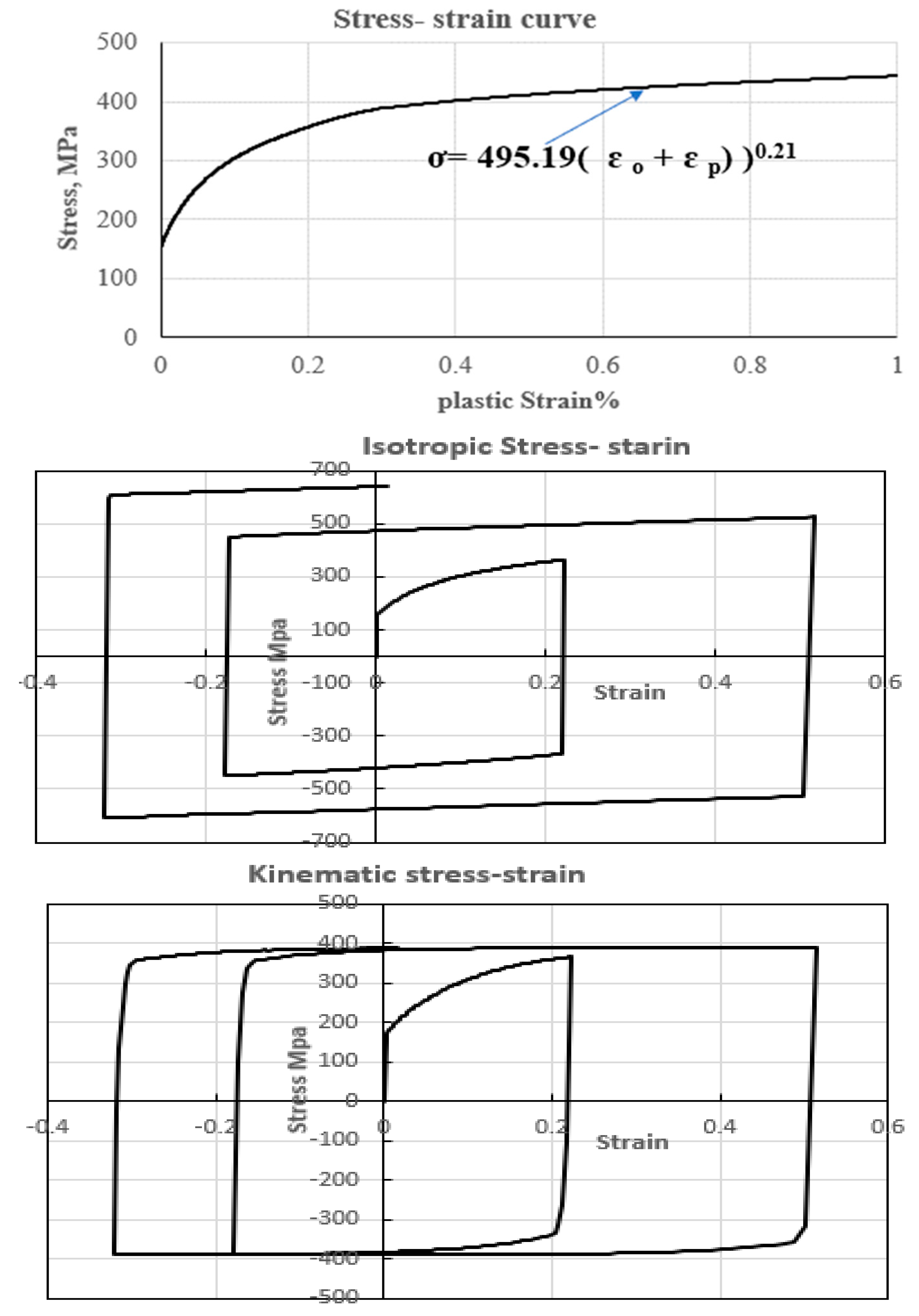
  • The material properties of FEM modeling
After the onset of plastic deformation (yield point), the stress generated in the material continues to grow as deformation increases. This phenomenon is called strain-hardening. Good forming remains below the necking level so that excessive thinning is avoided. Two different materials of strain hardening are modeled, such as the isotropic and kinematic hardening of materials. One of the most famous surface plasticity models is the Yoshida-Uemori [23] model (Figure 10), which has been frequently implemented in finite element software. The main advantage of this model is its applicability to any anisotropic yield criteria. Yield surface f, limit surface F, and back stress α and β are defined in the following equations:
f   = ϕ σ α Y = 0
F = ϕ σ β ( B + R ) = 0
d β = m b Y σ α β d ε p ¯
a = B + R − Y
dR = m (Rsat − R) dεp
α = α β = C [ a Y σ α a α ¯ α ] ε p ¯
The characteristics of the isotropic material properties and parameters of the Yoshida-Uemori models applied in this work are shown in Table 1 and Figure 11. The E, Ea and ξ are the initial Young’s modulus, saturated Young’s modulus, and coefficient for describing the change of Young’s modulus with plastic strain in the form of exponential function [23].

5. Multi Stages of FEM Modeling

The sequences of forming simulations of the target model comprise the following stages:

5.1. Forming Simulation Stage

In this stage, the FEM model is simulated using explicit software, LS-dyna [31]. The boundary conditions and forming contact surfaces are described as explained before. The objective of this stage is to simulate the forming process like the experimental model, as shown in Figure 3. A series of small incremental deformations using the rigid tool with predefined paths in x, y, and z directions is applied, as described in Figure 6.

5.2. Unclamping Stage

This stage describes the simulation of removing clamps from the blank. After the forming and unclamping processes, the deformed shape of the tool will be a combination of elastic and plastic deformation. The release of elastic deformation is the phenomenon of spring back. Here, this phenomenon is simulated using implicit software. The forming model, which is initially strained, is prevented from having a rigid body motion by constraining its translation movements for only three nodes, which are equal to 6 DOF.

5.3. Trimming Flanges Stage

This stage describes the simulation of cutting the flanges of the workpiece. Due to the trimming process of flanges, a spring back analysis is also simulated to release stresses after trimming using implicit software. Here, the rigid body motion of the blank is prevented. The stages of FEM modeling are shown in Figure 12.
The type of solver, termination time, and boundary conditions applied for each simulation stage are described in Table 2.

6. Characteristics of Accurate Numerical Modeling

A FEM model, furnished with a 5 mm mesh size, is analyzed to examine the forming properties, such as effective plastic strain and plate thickness distribution in the forming area.

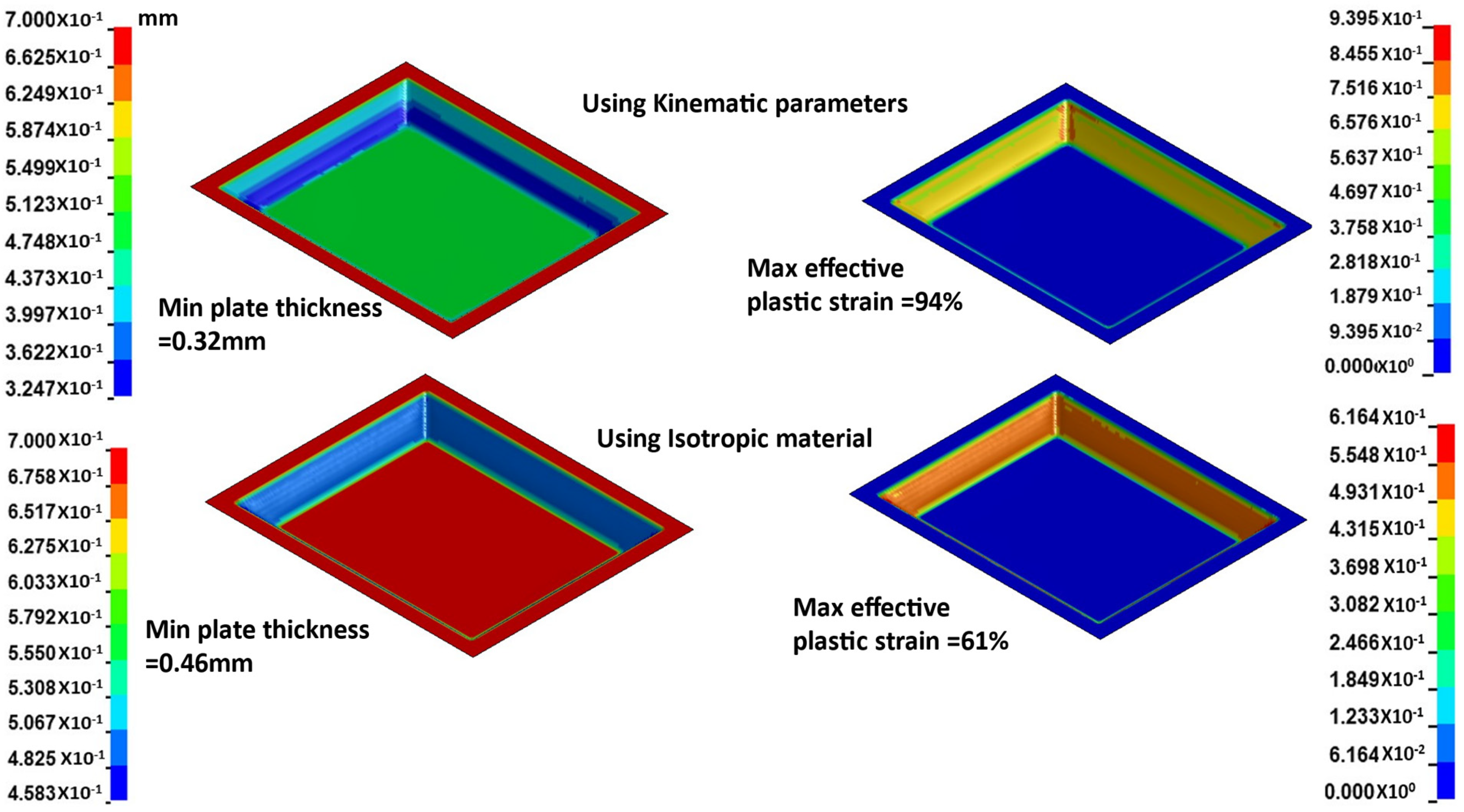
6.1. The Effective Plastic Strain

In this section, the effective plastic strain distribution helps in evaluating the formability of the material. It measures the ability of a material to undergo plastic deformation without failure or defects. By analyzing the effective plastic strain distribution after forming a simulation, it can be determined whether the model will deform uniformly or exhibit localized distortion. Figure 13 shows the distribution and contour of the effective plastic strain at section (x = 0) along the y-axis at the end of simulations (time = 17.9 s).
It was noticed that the effective plastic strain is uniformly distributed in the forming area, which exhibits better formability.

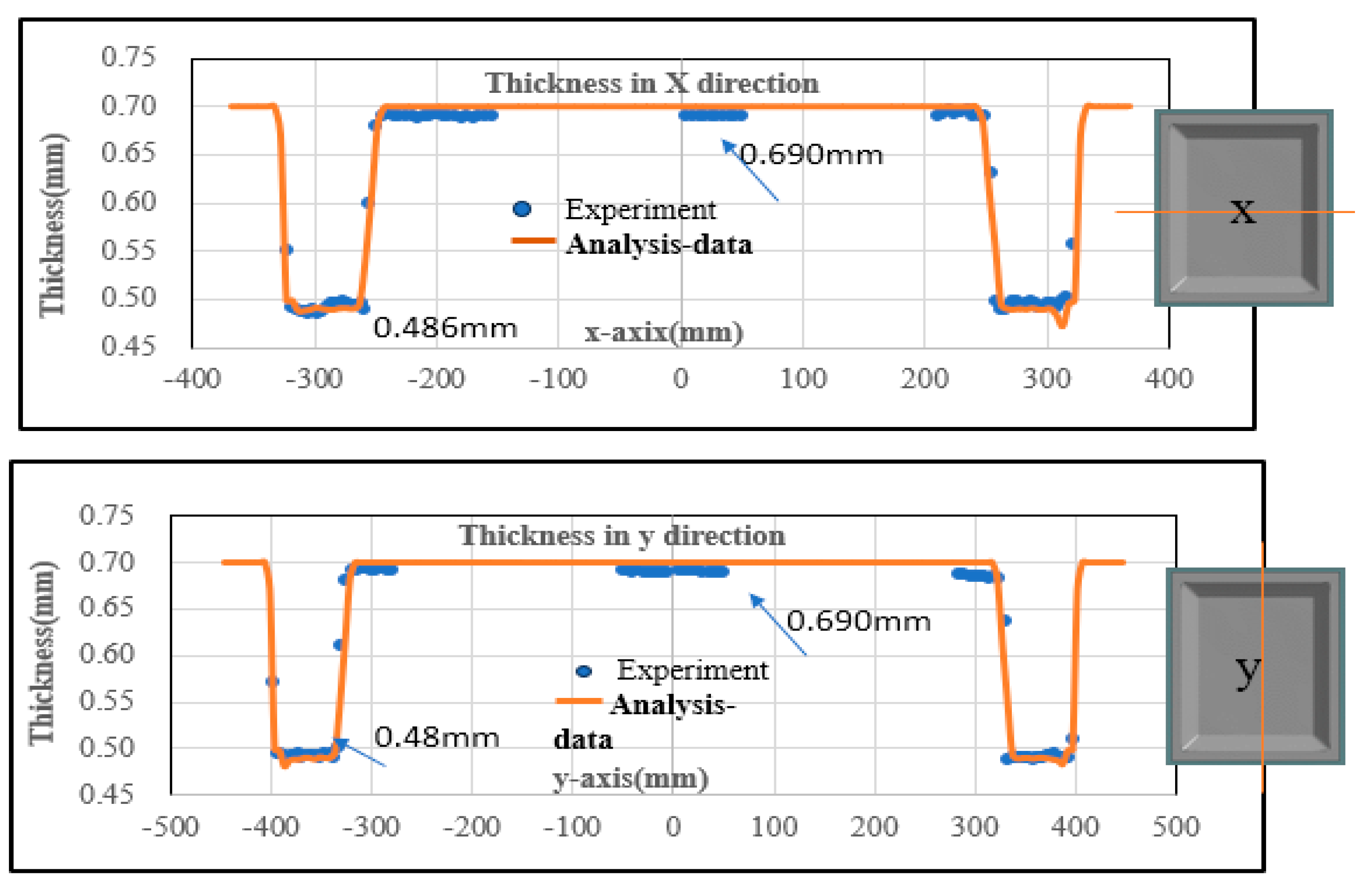
6.2. The Minimum Plate Thicknesses

Figure 14 shows a comparison between the plate thickness distribution after forming simulation along sections (X and Y) and the measured thicknesses in the experimental model (illustrated in Figure 4). It is noticed that the plate thickness after forming the simulation becomes a thinner value at the side equal to 0.48 mm, which agrees with the measured values (blue ones). The thinning reduction ratio represents an essential parameter for assessing the formability of materials. It provides insights into how easily a material can be deformed into a specific shape without cracking or failure. If the thinning reduction ratio exceeds a critical value, it may indicate excessive localized stretching or necking, which can lead to material failure. An error analysis of the minimum plate thickness by calculating the percentage of the difference between measured and analytical values is performed as shown in Table 3. It has been found that thickness prediction accuracy may be higher than 90%.

7. Results of Analyses

Two variables are investigated to examine the accuracy of the forming numerical model. Firstly, the forming characteristics are examined concerning the maximum effective plastic strain and minimum plate thickness. Secondly, the forming shape is examined after releasing the clamps and trimming flanges with the shape of the experimental (measured) model.

7.1. Optimum Element Size

A comparison between two FEM models with different element sizes, such as 2.5 mm and 5. Mm is performed. The two models have the same isotropic material properties and fixed boundary conditions (FBC). Figure 15 shows the contours of the plate thickness distribution and the effective plastic strain after forming simulation. In addition, Figure 16 shows a comparison between FEM forming geometry and the experimental shape (illustrated in Figure 3) after releasing the clamps and trimming processes.
As shown in Figure 15 and Figure 16, both the FEM models of 5 mm and 2.5 mm element sizes have attained acceptable forming characteristics (maximum effective plastic strain and acceptable plate thickness reduction ratio). Regarding forming shapes after releasing clamps and trimming stages, the FEM geometries deviated from the measured shape. However, the computational time of the model with a 5 mm element size (51 h) is much less than that of the model with a 2.5 mm element size (151 h). To acquire an accurate shape that is close to the shape of the measured model, different materials and boundary conditions are investigated.

7.2. Effective Material Properties

Based on the above results, a FEM model furnished with a 5 mm element size and a tool feed rate equal to 500 Vr is simulated for forming the plate with two different materials of strain hardening, such as isotropic and kinematic hardening, as described before in Section 4. Figure 17 shows the contours of the plate thickness distribution and the effective plastic strain after forming analysis. The simulation model with isotropic material has attained sufficient forming characteristics regarding thickness reduction ratio (0.34%) and maximum effective plastic stain distribution (0.61%). However, the forming geometry after releasing the clamps and trimming simulation deviates from the experimental shape, as shown in Figure 18.
Despite the simulation of the FEM model equipped with kinematic hardening of the material, it consumes a lot of CPU (72 h), and the thickness reduction ratio of the forming shape is 0.50%. Nevertheless, it has the maximum effective plastic stain distribution (0.93%) and a final forming geometry close to the measured geometry as shown in Figure 18. Therefore, the FEM model is characterized by kinematic hardening of material and has an element size equal to 5 mm, predicting acceptable forming geometry and efficient computing time after simulation stages.
Figure 19 summarizes a comparison between the previous FEM analyses when applying different boundary conditions. Figure 19a shows a plan view of the forming simulation at different heights of the model, starting from the top to the bottom of the model.
The experimental model nearly matches the FEM model using the kinematic hardening of the material. It is shown clearly that the model with kinematic properties and a contact boundary condition has attained a final simulation geometry close to the measured ones, as shown in Figure 19b. To evaluate a deviation of the FEM geometry from the experimental shape, the following error analysis is performed. Heights at different locations of the forming geometry for both models along section X are extracted. The percentage of the different values between measured and FEM geometry is calculated, as shown in Table 4.
Where Z1 and Z2 represent heights along section X, as shown in Figure 19b. The height’s locations are selected based on the maximum deviation. It is found from the above analysis that FEM geometry deviates about 2 to 3 mm from the measured geometry, as shown in Table 4.

8. Conclusions

The research work in this article involves the development of an advanced numerical model considering the complicated forming tool path, trimming, and spring back. Numerical modeling is designed to efficiently simulate the multi-stage deformation phenomenon of incremental sheet metal forming processes. The simulation accuracy and efficiency of numerical modeling for large-size and multi-stage incremental sheet forming were investigated. The following conclusions can be drawn:
  • Changing the tool feed rate in the numerical model from experimental 66.66 mm/s to 33,330 mm/s (500 Vr) will highly accelerate the simulation efficiency without losing its accuracy. The simulation time for the multi-stage incremental sheet forming with a large-size blank of 900 × 740 × 0.7 mm was reduced to 72 h, whose efficiency has been accepted by the automotive industries in the design and development phases.
  • The numerical model characterized by a Yoshida-Uemori kinematic material model and contact boundary condition for clamping obtained higher accuracy compared with the conventional isotropic hardening material model.
  • Compared with the measured thickness distribution and geometry shape, the thinning due to large-size incremental sheet forming and spring back after unclamping and trimming were accurately predicted using the developed numerical modeling. The thickness prediction accuracy can be higher than 90%, and the spring back prediction deviation may be less than 3 mm compared with measured values.

Author Contributions

Y.A.-N., methodology, writing, analysis; N.M., Conceptualization, supervision, resource; S.R., writing; K.M.; experiments, validation; H.M., discussions, funding. All authors have read and agreed to the published version of the manuscript.

Funding

This research received no external funding.

Data Availability Statement

There is no raw data to share here.

Acknowledgments

This work is partially supported by AMADA foundation, the program of OU (Osaka University) master plan and the program of JWRI International Joint Research Collaborators (JIJReC) as well as the joint research project between OU and Nissan Motor Co., Ltd.

Conflicts of Interest

Authors 4 and 5 were employed by the company Nissan Motor Co., Ltd. Japan. The remaining authors declare that the research was conducted in the absence of any commercial or financial relationships that could be construed as a potential conflict of interest.

References

  1. Danga, X.; Heb, K.; Zhangb, F.; Dua, R. A new flexible sheet metal forming method of incremental bending. In Proceedings of the 17th International Conference on Metal Forming, Toyohashi, Japan, 16–19 September 2018. [Google Scholar]
  2. Rozeman, S.; Adesta, E.Y.T.; Sophian, A.; Tomadi, S.H. Activities in stamping die manufacturing: A systematic literature review. Int. J. Eng. Mater. Manuf. 2023, 8, 21–35. [Google Scholar] [CrossRef]
  3. Ajay, C.V.; Boopathi, C.; Kavin, P. Incremental sheet metal forming (ISMF): A literature review. AIP Conf. Proc. 2019, 2128, 030012. [Google Scholar] [CrossRef]
  4. Kumar, Y.; Kumar, S. Incremental sheet forming (ISF). In Advances in Material Forming and Joining Topics in Mining, Metallurgy, and Materials Engineering; Springer: Berlin/Heidelberg, Germany, 2015. [Google Scholar]
  5. Ambrogio, I.; Costantino, I.; De Napoli, L.; Filice, L.; Fratini, L.; Muzzupappa, M. Influence of some relevant process parameters on the dimensional accuracy in incremental forming: A numerical and experimental investigation. J. Mater. Process. Technol. 2004, 153–154, 501–507. [Google Scholar] [CrossRef]
  6. Gohil, A.; Modi, B. Review of the effect of process parameters on performance measures in the incremental sheet forming process. Proc. Inst. Mech. Eng. Part B J. Eng. Manuf. 2021, 235, 303–332. [Google Scholar] [CrossRef]
  7. Nasulea, D.; Oancea, G. Incremental Deformation: A Literature Review. 2017. Available online: https://www.matec-conferences.org/articles/matecconf/abs/2017/35/matecconf_mse2017_03017/matecconf_mse2017_03017.html (accessed on 16 December 2023).
  8. Tegan, M.; Jack, J.; Matthew, D. Formability in single point incremental forming: A comparative analysis of the state of the art. CIRP J. Manuf. Sci. Technol. 2017, 16, 43–54. [Google Scholar]
  9. Kim, Y.H.; Park, J.J. Effect of process parameters on formability in incremental forming of sheet metal. J. Mater. Process. Technol. 2002, 130–131, 42–46. [Google Scholar] [CrossRef]
  10. Kumar, A.; Gulati, V.; Kumar, P.; Singh, H. forming force in incremental sheet forming: A comparative analysis of the state of the art. J. Braz. Soc. Mech. Sci. Eng. 2019, 41, 251. [Google Scholar] [CrossRef]
  11. Wu, S.; Ma, N.; Rashed, S.; Matsuoka, Y.; Lu, F.; Miyamoto, K. A position-adjustable universal backing plate to improve geometric accuracy in incremental sheet forming. Int. J. Adv. Manuf. Technol. 2022, 121, 8143–8158. [Google Scholar] [CrossRef]
  12. Wu, S.; Gao, L.; Matsuoka, Y.; Rashed, S.; Zhao, Y.; Ma, N. Multi-step toolpath approach to improve the dimensional accuracy of a non-axisymmetric part in incremental sheet forming and its mechanism analysis. J. Mech. Sci. Technol. 2022, 36, 1–12. Available online: https://link.springer.com/article/10.1007/s12206-022-0333-1 (accessed on 1 December 2023). [CrossRef]
  13. Yamashita, M.; Gotoh, M.; Atsumi, S. Numerical simulation of incremental forming of sheet metal. J. Mater. Process. Technol. 2008, 199, 163–173. [Google Scholar] [CrossRef]
  14. Trzepiecinski, T.; Lemu, H. Recent development and trends in friction testing for conventional and incremental sheet forming. Metals 2020, 10, 47. [Google Scholar] [CrossRef]
  15. Wu, S.; Geng, P.; Ma, N.; Lu, F. Contact-induced vibration tool in incremental sheet forming for formability improvement of aluminum sheets. J. Mater. Res. Technol. 2022, 17, 1363–1379. [Google Scholar] [CrossRef]
  16. Kim, T.J.; Yang, D.Y. Improvement of formability for the incremental sheet metal forming process. Int. J. Mech. Sci. 2002, 42, 1271–1286. [Google Scholar] [CrossRef]
  17. Tamer, M.E.; Music, O.; Ozdemir, I.; Baranoglu, B.; Sakin, A.; Durgun, I. Simulation for incremental sheet forming process: A comparison of implicit and explicit finite element analysis with experimental data. In Proceedings of the 7th International Conference and Exhibition on Design and Production of Machines and Dies/Molds, Antalya, Turkey, 20–23 June 2013. [Google Scholar]
  18. Zhaobing, L. Heat-assisted incremental sheet forming: A state-of-the-art review. Int. J. Adv. Manuf. Technol. 2018, 98, 2987–3003. [Google Scholar] [CrossRef]
  19. Vrh, M.; Halilovics, M.; Starman, B.; Stok, B. Modeling of spring back in sheet metal forming. Int. J. Mater. Form. 2009, 2, 825–828. [Google Scholar] [CrossRef]
  20. Stefanos, C.S.; Georgios, E. Stavroulakis, Spring back prediction in sheet Metal forming based on finite element analysis and artificial. neural network approach. Appl. Mech. 2020, 1, 97–110. [Google Scholar] [CrossRef]
  21. Serkan, T. Parameters determination of Yoshida Uemori model through optimization process of cyclic tension-compression test and V-bending spring back. Lat. Am. J. Solid Struct. 2016, 13, 1893–1911. [Google Scholar]
  22. Starman, B.; VrhMarko, M.; Halilovič and, V. Advanced modeling of sheet metal forming considering anisotropy and Young’s modulus evolution. J. Mech. Eng. 2014, 60, 84–92. [Google Scholar] [CrossRef]
  23. Yoshida, F.; Uemori, T. A model of large-strain cyclic plasticity describing the Bauschinger effect and work hardening stagnation. Int. J. Plast. 2002, 18, 661–686. [Google Scholar] [CrossRef]
  24. Xia, X.; Gong, M.; Wang, T.; Liu, Y.; Zhang, H.; Zhang, Z. Parameter identification of the Yoshida-Uemori hardening model for remanufacturing. Metals 2021, 11, 1859. [Google Scholar] [CrossRef]
  25. Oleksik, V.; Trzepieciński, T.; Szpunar, M.; Chordia, Ł.; Ficek, D.; Szczesny, I. Single-point incremental forming of titanium and titanium alloy sheets. Materials 2021, 14, 6372. [Google Scholar] [CrossRef] [PubMed]
  26. Zhu, H.; Ou, H.; Popov, A. Incremental sheet forming of thermoplastics: A review. Int. J. Adv. Manuf. Technol. 2020, 111, 565–587. [Google Scholar] [CrossRef]
  27. Ullah, P.; Li, X.; Li, D. Fast simulation of incremental sheet metal forming by multi-tooling. J. Manuf. Process. 2022, 84, 669–680. [Google Scholar] [CrossRef]
  28. Markus, B. Fast simulation of incremental sheet metal forming by adaptive remeshing and sub-cycling. Int. J. Mater. Form. 2016, 9, 353–360. [Google Scholar]
  29. Nitin, H.H. Automated Modeling and Remeshing in Metal Forming Simulation. Ph.D. Thesis, Rensselaer Polytechnic Institute, Troy, NY, USA, 2003. [Google Scholar]
  30. Abdel-Nasser, Y.; Fan, H.; Zhu, X.; Ma, N. Moving Mesh Refining and Coarsening for Increment Sheet Forming Simulation; Workshop at Osaka: Osaka, Japan, 2018. [Google Scholar]
  31. LS-DYNA/Implicit Software. 2017. Available online: https://lsdyna.ansys.com/manuals/ (accessed on 16 December 2023).
Figure 1. (a) Layout and dimensions of experiment elements of the ISF. (b) Experiment elements of ISF.
Jmmp 08 00003 g001
Figure 2. Tool paths of the experimental model in X, Y, and Z directions.
Jmmp 08 00003 g002
Figure 3. Target and experimental models after unclamping and trimming flanges.
Jmmp 08 00003 g003
Figure 4. Samples of measured thicknesses of the experimental model along X and Y directions.
Jmmp 08 00003 g004
Figure 5. Sizes of the FEM model.
Jmmp 08 00003 g005
Figure 6. Characteristics of the tool path in the simulation model.
Jmmp 08 00003 g006
Figure 7. Schematic illustration of tool characteristics.
Jmmp 08 00003 g007
Figure 8. FEM models with different boundary conditions.
Jmmp 08 00003 g008
Figure 9. FEM models with different element sizes.
Jmmp 08 00003 g009
Figure 10. Schematic illustration of the two moving surfaces of the Y-U model.
Jmmp 08 00003 g010
Figure 11. Isotropic and kinematic properties of the material.
Jmmp 08 00003 g011
Figure 12. Stages of FEM modeling simulations.
Jmmp 08 00003 g012
Figure 13. Distribution of effective plastic strain at section (x = 0) along the Y-axis.
Jmmp 08 00003 g013
Figure 14. Comparison of plate thickness distribution in FEM and experimental models along sections X and Y.
Jmmp 08 00003 g014
Figure 15. Contours of plate thickness and effective plastic strain (after forming stage-size element effect).
Jmmp 08 00003 g015
Figure 16. Comparison between FEM geometry and experimental shape at section X (after unclamping and trimming stages-size element effect).
Jmmp 08 00003 g016
Figure 17. Contours of plate thickness and effective plastic strain (after forming stage-material effect).
Jmmp 08 00003 g017
Figure 18. Comparison between FEM and experimental models in Section X (after unclamping and trimming stages-material effect).
Jmmp 08 00003 g018
Figure 19. (a) A plan view showing the forming simulation after trimming compared with the measured model. (b) Comparison between FEM and experimental models in Section X (after unclamping and trimming stages-boundary effect).
Jmmp 08 00003 g019
Table 1. Properties of isotropic material and Parameters of kinematics material.
Density ρ [ton/mm3]E [Mpa]Ea [Mpa]ξAnisotropy Ratio
7.8 × 10−92.05 × 1051.50 × 10530.81.6
Y [Mpa]CB [Mpa]Rsat [Mpa]b [Mpa]
15030017019020
mh
100.5
Table 2. FEM characteristics for each simulation stage.
Simulation StageSolverTermination
Time
Boundary Conditions
FormingExplicit17.9 sContact area
Release the clampsImplicit1 s6 DOF of 3 nodes
TrimmingImplicit1 s6 DOF of 3 nodes
Table 3. Error analysis of the minimum plate thickness.
ExperimentX-Axis Y-Axis% in X% in Y
Min Thick (Left side)0.4860.49−0.00430.0188
Min Thick (Right side)0.490.4870.03620.0075
FEM
Min Thick (Left side)0.4880.4807
Min Thick (Right side)0.472 0.4833
Table 4. Error analysis of geometry deviation in the Z direction along the x-axis.
ExperimentZ1 (mm) Z2 (mm)% in Z1% in Z2
Height (Left side)53.8547.2060.01550.05293
Height (Right side)55.44646.210.05790.06655
FEM
Height (Left side)53.01244.682
Height (Right side)52.23143.125
Disclaimer/Publisher’s Note: The statements, opinions and data contained in all publications are solely those of the individual author(s) and contributor(s) and not of MDPI and/or the editor(s). MDPI and/or the editor(s) disclaim responsibility for any injury to people or property resulting from any ideas, methods, instructions or products referred to in the content.

