
Advancements in Metal Additive Manufacturing: A Comprehensive Review of Material Extrusion with Highly Filled Polymers

Abstract
:1. Introduction
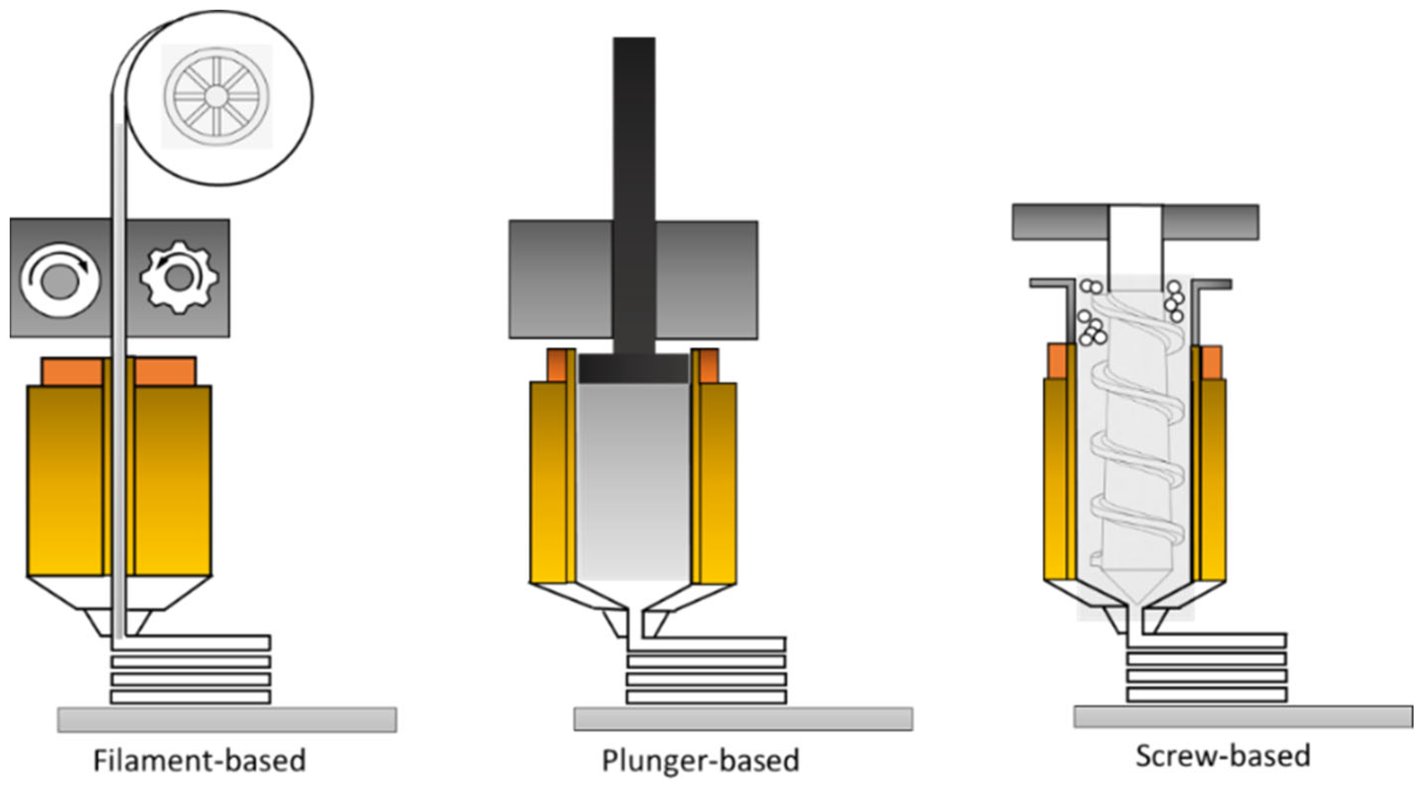
1.1. Material Extrusion with Filaments
1.2. Material Extrusion with Plungers
1.3. Material Extrusion with Screws
2. Fabrication of Metal Objects with High-Loaded Powders Using Filament-Based Material Extrusion (MEX)
2.1. Choice of Powder
- The powder size has to be small;
- The powder has to disperse well with the binder;
- Sintering is required to have significant densification;
- The melting and sintering temperatures should be adequately elevated to avoid interfering with the debinding process.
2.2. Choice of Binder System
- Primary or main binder: This constituent holds the largest proportion within the formulation (it typically contains 50–90 vol.% of the whole binder system) and can be effectively removed at low temperatures. Commonly employed primary binder materials encompass carnauba wax; paraffin wax; sometimes agarose, in certain practices; etc. Waxes primarily serve to lower the feedstock’s viscosity, achieving favorable flow characteristics, and to improve filament rigidity. However, waxes should be utilized within prescribed limits, as exceeding these limits can diminish the mechanical attributes of both filaments and the resulting printed object.
- Secondary or backbone binder: This element maintains the structural integrity of the product after the initial removal of the main binder during the first debinding phase. The secondary binder is typically eliminated through thermal degradation in the second stage of debinding, which then progresses to the sintering process. The proportion of the secondary binder ranges from 0% to 50% of the total binder system volume. Commonly utilized secondary binder materials include polypropylene (PP), low-density polyethylene (LDPE), high-density polyethylene (HDPE), ethylene vinyl acetate (EVA), polyethylene glycol (PEG), polystyrene (PS), and several others. These polymers have a short molecular chain length that permits them to decompose with relatively small volume variations, reducing the chance of problems during debinding and sintering. Other advantages of using these polymers are their highly availability, low cost, and less carbon contamination during burnout in the thermal debinding stage [48].
- Additives: Additional components, such as compatibilizers, stabilizers, dispersing agents, and surfactants, play a vital role in promoting effective diffusion between the powder and binder. These additives prevent phase separation and agglomeration. Additives typically constitute 0–10% of the total volume within the binder system. Among the commonly employed additives, stearic acid stands out as a frequently used example. Furthermore, it is important to use additives within specified limits; surpassing these limits can lead to the formation of defects, such as bubbles and cracks, in the final product.
2.3. Compounding of Feedstock and Filaments
2.4. Shaping

2.5. Debinding
- Solvent debinding: This method involves immersing green parts in liquid or gaseous solvents, such as heptane, ethanol, acetone, and hexane, among others. Typically, a temperature range of 50–70 °C is applied, depending on the specific solvent used. The fundamental principle behind this process is that MEX-printed components can be introduced into an environment saturated with a solvent. Subsequently, the primary binder within the component undergoes a phase change, transitioning from a solid to a liquid state, and is thus removed from the component structure. This action effectively opens a network of pores, facilitating the subsequent removal of the backbone binder during the thermal debinding stage [60,115]. It is crucial to ensure compatibility between the solvent and the binder material for successful solvent debinding. Additionally, the debinding time is significantly influenced by the thickness of the MEX-printed component, with thicker components and smaller particle sizes requiring longer removal times. Critical parameters in the debinding process encompass the selection of an optimal temperature for solvent debinding. Excessively low temperatures may induce rapid solvent diffusion within the green compact, resulting in the swelling of the green part. Consequently, this swelling can cause pronounced internal stress within the component, ultimately culminating in the formation of cracks. Conversely, excessively high temperatures pose the risk of green component collapse due to the softening of the binder material [50,90,93].
- Thermal debinding: This technique is based on the thermal degradation of the binders. The components should be placed inside the debinding furnace, and the temperature should be increased up to the evaporation temperature of the polymer materials used. Once the evaporation temperature is reached, the ramping temperature is set on hold for a certain time until the whole polymer is decomposed. Polymer removal through thermal debinding involves chemical and physical methods. The chemical process occurs due to thermal degradation based on the continuous dissociation of polymers to generate low-molecular-weight volatile products. The physical process involves the diffusion of volatile products onto and out of the surface of the component [101]. Compact heating depends on heat transfer and the reaction enthalpies correlated with the dissociation of polymeric chains, leading to thermal–kinetic results that link to the chemical–physical aspects. The degradation temperature and time are dependent on the nature of the polymer used and its thermal conductivity [48,116].
- Catalytic debinding: This method combines both solvent and thermal debinding mechanisms, primarily relying on the catalytic action of acids to remove the binder. During this process, catalytic acids play a pivotal role in initiating the dissociation of polymeric chains within the material. These catalysts are specifically designed to lower the temperature at which the polymeric chains break down. Typically, the debinding chamber contains a controlled concentration of catalytic acid vapor, with nitric acid being a commonly employed catalyst. Nitrogen gas is often introduced to prevent oxidation during the process [48]. Catalytic debinding is known for its relative efficiency and speed compared with other debinding techniques. However, it is worth noting that this method is not universally applicable to all metals, posing a significant limitation. Some metals may risk contamination or corrosion during catalytic debinding, underscoring the need for careful selection of the appropriate acid to safeguard equipment integrity. Catalytic debinding finds extensive use in the powder injection molding (PIM) industry, with polyoxymethylene (POM) serving as a notable example, as it undergoes decomposition under the influence of acid attack [101].
2.6. Sintering
2.6.1. Mass Transport Mechanisms
2.6.2. Stages of Sintering
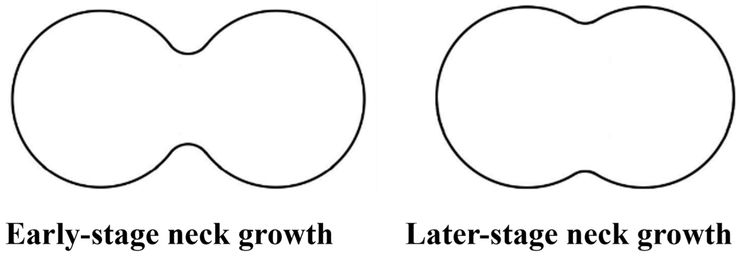
- Neck formation: This initial sintering stage marks the onset of particle-to-particle interactions and the simultaneous smoothing of the particles’ free surfaces. At this point, the formation of “necks” at interaction points is driven by mass transport mechanisms, including evaporation–condensation, surface diffusion, and volume diffusion (Figure 9). A modest degree of shrinkage occurs in this early phase. Following the establishment of these necks, the compaction of the material experiences an increase of up to 3% in density. This progression is notably rapid due to the exposure of the powder to elevated temperatures, owing to the elevated surface area and the pronounced driving force promoting sintering.
- Densification: During this phase, with increasing temperatures, the necks between particles undergo expansion owing to the influence of various mass transport mechanisms (Figure 10). These mechanisms encompass grain boundary diffusion, surface diffusion, viscous flow, lattice diffusion, plastic flow, and evaporation–condensation processes. Furthermore, the porosity within the component diminishes as sintering progresses.
- Grain growth: This represents the final stage in the sintering process, commencing when the material reaches approximately 93–95% of its theoretical density, as most of the porosity has already been isolated. In an ideal scenario, by the conclusion of this phase, all remaining porosity is eliminated. The complete eradication of porosity during the last stage of sintering is achievable only when all pores are either interconnected or follow distinct, unobstructed diffusion pathways along grain boundaries. Such favorable conditions take place only if the pores go along with the direction of the grain boundaries and do not stay within the grains. However, if sintering is excessively prolonged, grain size may undergo enlargement, which can subsequently lead to a decline in mechanical properties.
2.6.3. Sintering Parameters
2.6.4. Sintering Atmosphere
2.6.5. Shrinkage and Densification
3. Comparison of MEX and Other Manufacturing Processes

| Process | Yield Strength (MPa) | Tensile Strength (MPa) | Elastic Modulus (Gpa) | Densification (%) | Ref. |
|---|---|---|---|---|---|
| MEX | 167 | 465 | 152 | 98.5 | [61] |
| MEX | 234–251 | 521–561 | n.d. | n.d. | [44] |
| MEX | 500 | 900 | n.d. | 95 | [60] |
| MEX | 155–165 | 500–520 | 210 | 98.3–99.5 | [59] |
| MEX | 167 | 436 | n.d. | n.d. | [136] |
| MEX | 125–161 | 405–464 | n.d. | ~95.3 | [134] |
| MEX | ~130 | ~460 | 150–230 | n.d. | [137] |
| MEX | 139–161 | 441–473 | 172–203 | n.d. | [138] |
| MIM | 170–205 | 460–560 | n.d. | 98.5 | [141] |
| MIM | n.d. | 527–590 | n.d. | 97.7–99.1 | [142] |
| DED | 405–415 | 620–720 | n.d. | n.d. | [143] |
| DED | 580 | 900 | n.d. | n.d. | [144] |
| SLM | 590 | 700 | 227.3 | > 99 | [61] |
| SLM | 208.8–469.6 | 486.4–644.3 | 141–205 | > 99.3 | [145] |
| PBF | 450–525 | 620–650 | n.d. | 99 | [146] |
| PBF | 400–420 | 550–580 | 180–202 | 98 | [147] |
| BJ | n.d. | 700–780 | n.d. | n.d. | [148] |
| BJ | 214 | 517 | n.d. | 98.7 | [118] |
| Hot rolling | n.d. | 585 | 245 | n.d. | [149] |
| Flat rolling | 170 | 485 | n.d. | n.d. | [136] |
| Cast | n.d. | 575 | 288 | n.d. | [150] |
4. Conclusions
5. Research Outlook
Author Contributions
Funding
Institutional Review Board Statement
Data Availability Statement
Acknowledgments
Conflicts of Interest
References
- Riecker, S.; Hein, S.; Studnitzky, T. 3D Printing of Metal Parts by Means of Fused Filament Fabrication—A Non Beam-Based Approach. In Proceedings of the EuroPM 2017–AM Alternative Technologies, Milan, Italy, 1–5 October 2017. [Google Scholar]
- Andersen, O.; Riecker, S.; Studnitzky, T.; Hein, S.; Lohse, U.; Kie, B. Manufacturing and Properties of Metal Parts Made by Fused Filament Fabrication. Powder Metall. 2018, 18, 2–7. [Google Scholar]
- Masood, S.H. Advances in Fused Deposition Modeling. In Comprehensive Materials Processing; Elsevier B.V: Amsterdam, The Netherlands, 2014; Volume 10, pp. 69–91. ISBN 9780080965338. [Google Scholar]
- Gao, W.; Zhang, Y.; Ramanujan, D.; Ramani, K.; Chen, Y.; Williams, C.B.; Wang, C.C.L.; Shin, Y.C.; Zhang, S.; Zavattieri, P.D. The Status, Challenges, and Future of Additive Manufacturing in Engineering. CAD Comput. Aided Des. 2015, 69, 65–89. [Google Scholar] [CrossRef]
- Turner, B.N.; Strong, R.; Gold, S.A. A Review of Melt Extrusion Additive Manufacturing Processes: I. Process Design and Modeling. Rapid Prototyp. J. 2014, 20, 192–204. [Google Scholar] [CrossRef]
- Belei, C.; Meier, B.; Amancio-Filho, S.T. Manufacturing of Metal–Polymer Hybrid Parts Using a Desktop 3-Axis Fused Filament Fabrication 3D-Printer. Metals 2023, 13, 1262. [Google Scholar] [CrossRef]
- Podmiljšak, B.; Kobe, S.; Tomše, T.; Bek, M.; Kotnik, T.; Slemenik Perše, L.; Žagar, E.; Saje, B.; Žužek, K.; Šturm, S. Additive-Manufactured Anisotropic Magnets for Harsh Environments. J. Magn. Magn. Mater. 2023, 586, 171165. [Google Scholar] [CrossRef]
- Ramazani, H.; Kami, A. Metal FDM, a New Extrusion-Based Additive Manufacturing Technology for Manufacturing of Metallic Parts: A Review. Prog. Addit. Manuf. 2022, 7, 609–626. [Google Scholar] [CrossRef]
- Smith, W.C.; Dean, R.W. Structural Characteristics of Fused Deposition Modeling Polycarbonate Material. Polym. Test. 2013, 32, 1306–1312. [Google Scholar] [CrossRef]
- Rane, K.; Strano, M. A Comprehensive Review of Extrusion-Based Additive Manufacturing Processes for Rapid Production of Metallic and Ceramic Parts. Adv. Manuf. 2019, 7, 155–173. [Google Scholar] [CrossRef]
- Zhou, W.; Lin, J.; Dean, T.A. Microstructure and Mechanical Properties of Curved AZ31 Magnesium Alloy Profiles Produced by Differential Velocity Sideways Extrusion. J. Magnes. Alloy. 2023, 11, 493–508. [Google Scholar] [CrossRef]
- Zhang, Z.; Zhou, W.; Shi, Z.; Lin, J. Investigation of Die Designs on Welding Quality and Billet Material Utilisation for Multi-Container Extrusion of Wide Stiffened Aluminium Panels. Int. J. Adv. Manuf. Technol. 2023, 127, 4149–4162. [Google Scholar] [CrossRef]
- Bragaglia, M.; Sadaf, M.; Rinaldi, M.; Nanni, F. PEEK-Titanium Dioxide 3D Printable Filaments: Influence of TiO2 on UV Resistance. In Proceedings of the ECNP Congress, San Sabestian, Spain, 3–5 October 2018; p. 1. [Google Scholar]
- Gonzalez-Gutierrez, J.; Cano, S.; Schuschnigg, S.; Kukla, C.; Sapkota, J.; Holzer, C. Additive Manufacturing of Metallic and Ceramic Components by the Material Extrusion of Highly-Filled Polymers: A Review and Future Perspectives. Materials 2018, 11, 840. [Google Scholar] [CrossRef] [PubMed]
- Quarto, M.; Giardini, C. Additive Manufacturing of Metal Filament: When It Can Replace Metal Injection Moulding. Prog. Addit. Manuf. 2023, 8, 561–570. [Google Scholar] [CrossRef]
- Singh, N.; Siddiqui, H.; Koyalada, B.S.R.; Mandal, A.; Chauhan, V.; Natarajan, S.; Kumar, S.; Goswami, M.; Kumar, S. Recent Advancements in Additive Manufacturing (AM) Techniques: A Forward-Looking Review. Met. Mater. Int. 2023, 29, 2119–2136. [Google Scholar] [CrossRef]
- Tedla, G.; Rogers, K. Characterization of 3D Printing Filaments Containing Metal Additives and Their Particulate Emissions. Sci. Total Environ. 2023, 875, 162648. [Google Scholar] [CrossRef] [PubMed]
- Stratasys Wepbage. 2016. Available online: http://www.stratasys.com/ (accessed on 20 October 2016).
- Edgar, J.; Tint, S. Additive Manufacturing Technologies: 3D Printing, Rapid Prototyping, and Direct Digital Manufacturing, 2nd Edition. Johnson Matthey Technol. Rev. 2015, 59, 193–198. [Google Scholar] [CrossRef]
- Pepelnjak, T.; Stojšić, J.; Sevšek, L.; Movrin, D.; Milutinović, M. Influence of Process Parameters on the Characteristics of Additively Manufactured Parts Made from Advanced Biopolymers. Polymers 2023, 15, 716. [Google Scholar] [CrossRef] [PubMed]
- Carneiro, O.S.; Silva, A.F.; Gomes, R. Fused Deposition Modeling with Polypropylene. Mater. Des. 2015, 83, 768–776. [Google Scholar] [CrossRef]
- Chua, C.K.; Leong, K.F. 3D Printing and Additive Manufacturing State of the Industry, Annual Worldwide Progress Report; Wohlers Assosiates: Fort Collins, CO, USA, 2017. [Google Scholar]
- Valkenaers, H.; Vogeler, F.; Ferraris, E.; Voet, A.; Kruth, J.-P. A Novel Approach to Additive Manufacturing: Screw Extrusion 3D-Printing. In Proceedings of the 10th International Conference on Multi-Material Micro Manufacture, San Sebastian, Spain, 8–10 October 2013; pp. 235–238. [Google Scholar]
- Campbell, I.; Wohlers, T. Markforged: Taking a Different Approach to Metal Additive Manufacturing. Metal AM [Online]. Available online: https://www.metal-am.com/wp-content/uploads/sites/4/2017/06/MAGAZINE-Metal-AM-Summer-2017-PDF-sp.pdf (accessed on 11 July 2017).
- Schuh, C.A.; Myerberg, J.S.; Fulop, R.; Chiang, Y.-M.; Hart, A.J.; Schroers, J.; Vereminski, M.D.; Mykulowycz, N.; Shim, J.J.; Fontana, R. Methods and Systems for Additive Manufacturing. International Patent PCT/US2016/067378, 30 June 2016. [Google Scholar]
- Martínez-Vázquez, F.J.; Pajares, A.; Miranda, P. A Simple Graphite-Based Support Material for Robocasting of Ceramic Parts. J. Eur. Ceram. Soc. 2018, 38, 2247–2250. [Google Scholar] [CrossRef]
- Cesarano, J. A Review of Robocasting Technology. Mater. Res. Soc. Symp. Proc. 1999, 542, 133–139. [Google Scholar] [CrossRef]
- Gibson, I.; Rosen, D.W.; Stucker, B. Additive Manufacturing Technologies. In Rapid Prototyping to Direct Digital Manufacturing; Springer International Publishing: Berlin, Germany, 2010; pp. 406–407. [Google Scholar]
- Bose, A.; Schuh, C.A.; Tobia, J.C.; Tuncer, N.; Mykulowycz, N.M.; Preston, A.; Barbati, A.C.; Kernan, B.; Gibson, M.A.; Krause, D.; et al. Traditional and Additive Manufacturing of a New Tungsten Heavy Alloy Alternative. Int. J. Refract. Met. Hard Mater. 2018, 73, 22–28. [Google Scholar] [CrossRef]
- Bankapalli, N.K.; Gupta, V.; Saxena, P.; Bajpai, A.; Lahoda, C.; Polte, J. Filament Fabrication and Subsequent Additive Manufacturing, Debinding, and Sintering for Extrusion-Based Metal Additive Manufacturing and Their Applications: A Review. Compos. Part B Eng. 2023, 264, 110915. [Google Scholar] [CrossRef]
- Bellini, A.; Shor, L.; Guceri, S.I. New Developments in Fused Deposition Modeling of Ceramics. Rapid Prototyp. J. 2005, 11, 214–220. [Google Scholar] [CrossRef]
- Drescher, P.; Lieberwirth, C.; Seitz, H. Process and Installation for Manufacturing the Additive of Amorphous Crystalline and/or Semi-Crystalline Metal Components—Selective Amorphous Metal Extrusion (SAME). DE Patent 201410018080, 6 December 2014. [Google Scholar]
- AIM3D GmbH. Edelstahl. 2017. Available online: http://www.aim3d.de/Materialien/Edelstaehle/ (accessed on 7 July 2017).
- Pollen AM Inc. Meet PAM: Pellet Additive Manufacturing. Available online: https://www.pollen.am (accessed on 22 August 2017).
- Koslow, T. Pollen Introduces Pam: Their New Professional-Grade Multi-Material 3D Printer. Available online: https://3dprint.com/140595/Pollen-Pam-Multi-Material/ (accessed on 22 August 2017).
- Li, L.; Tirado, A.; Nlebedim, I.C.; Rios, O.; Post, B.; Kunc, V.; Lowden, R.R.; Lara-Curzio, E.; Fredette, R.; Ormerod, J.; et al. Big Area Additive Manufacturing of High Performance Bonded NdFeB Magnets. Sci. Rep. 2016, 6, 36212. [Google Scholar] [CrossRef]
- Cincinnati Inc. BAAM: Fact Sheet. Available online: https://wwwassets.e-ci.com/PDF/Products/baam-fact-sheet.pdf (accessed on 7 June 2017).
- Godec, D.; Cano, S.; Holzer, C.; Gonzalez-Gutierrez, J. Optimization of the 3D Printing Parameters for Tensile Properties of Specimens Produced by Fused Filament Fabrication of 17-4PH Stainless Steel. Materials 2020, 13, 774. [Google Scholar] [CrossRef] [PubMed]
- Galati, M.; Minetola, P. Analysis of Density, Roughness, and Accuracy of the Atomic Diffusion Additive Manufacturing (ADAM) Process for Metal Parts. Materials 2019, 12, 4122. [Google Scholar] [CrossRef] [PubMed]
- Bouaziz, M.A.; Djouda, J.M.; Kauffmann, J.; Hild, F. Microscale Mechanical Characterization of 17-4PH Stainless Steel Fabricated by Atomic Diffusion Additive Manufacturing (ADAM). Procedia Struct. Integr. 2020, 28, 1039–1046. [Google Scholar] [CrossRef]
- Singh, G.; Missiaen, J.-M.; Bouvard, D.; Chaix, J.-M. Additive Manufacturing of 17–4 PH Steel Using Metal Injection Molding Feedstock: Analysis of 3D Extrusion Printing, Debinding and Sintering. Addit. Manuf. 2021, 47, 102287. [Google Scholar] [CrossRef]
- Strano, M.; Rane, K.; Farid, M.A.; Mussi, V.; Zaragoza, V.; Monno, M. Extrusion-Based Additive Manufacturing of Forming and Molding Tools. Int. J. Adv. Manuf. Technol. 2021. [Google Scholar] [CrossRef]
- Kurose, T.; Abe, Y.; Santos, M.V.A.; Kanaya, Y.; Ishigami, A.; Tanaka, S.; Ito, H. Influence of the Layer Directions on the Properties of 316l Stainless Steel Parts Fabricated through Fused Deposition of Metals. Materials 2020, 13, 2493. [Google Scholar] [CrossRef]
- Poszvek, G.; Stattler, G.; Markl, E.; Seemann, R.; Lackner, M. Fused Filament Fabrication of Metallic Components for Semi-Professional and Home Use. In Proceedings of the Digital Conversion on the Way to Industry 4.0, Online, Turkey, 24–26 September 2020; Durakbasa, N.M., Gençyilmaz, M.G., Eds.; Springer International Publishing: Cham, Switzerland, 2021; pp. 140–149. [Google Scholar]
- Hassan, W.; Farid, M.A.; Tosi, A.; Rane, K.; Strano, M. The Effect of Printing Parameters on Sintered Properties of Extrusion-Based Additively Manufactured Stainless Steel 316L Parts. Int. J. Adv. Manuf. Technol. 2021, 114, 3057–3067. [Google Scholar] [CrossRef]
- Sadaf, M. Additive Manufacturing of Metals Via Material Extrusion: Ph. D. Program in Design, Manufacturing, and Operation Engineering. Ph.D. Thesis, Università degli Studi di Roma Tor Vergata, Rome, Italy, 2022. [Google Scholar]
- Heaney, D.F. Powders for Metal Injection Molding (MIM), In Handbook of Metal Injection Molding; Heaney, D.F., Ed.; Woodhead Publishing: Cambridge, UK, 2012. [Google Scholar]
- Engström, S. Metal Injection Molding: A Review of the MIM Process and Its Optimization. Master's Thesis, Arcada University of Applied Sciences, Helsinki, Finland, 2017. [Google Scholar]
- Beran, T.; Mulholland, T.; Henning, F.; Rudolph, N.; Osswald, T.A. Nozzle Clogging Factors during Fused Filament Fabrication of Spherical Particle Filled Polymers. Addit. Manuf. 2018, 23, 206–214. [Google Scholar] [CrossRef]
- Gonzlez-Gutirrez, J.; Beulke, G.; Emri, I. Powder Injection Molding of Metal and Ceramic Parts. In Some Critical Issues for Injection Molding; IntechOpen: London, UK, 2012; pp. 65–86. [Google Scholar]
- Nötzel, D.; Eickhoff, R.; Hanemann, T. Fused Filament Fabrication of Small Ceramic Components. Materials 2018, 11, 1463. [Google Scholar] [CrossRef]
- Kariz, M.; Sernek, M.; Obućina, M.; Kuzman, M.K. Effect of Wood Content in FDM Filament on Properties of 3D Printed Parts. Mater. Today Commun. 2018, 14, 135–140. [Google Scholar] [CrossRef]
- Kukla, C.; Gonzalez-Gutierrez, J.; Duretek, I.; Schuschnigg, S.; Holzer, C.; Kukla, C.; Gonzalez-gutierrez, J.; Duretek, I. Effect of Particle Size on the Properties of Highly-Filled Polymers for Fused Filament Fabrication. In Proceedings of the American Institute of Physics, Provo, UT, USA, 16–21 July 2017; Volume 19, pp. 2–5. [Google Scholar]
- Brostow, W.; Buchman, A.; Buchman, E.; Olea-mejia, O. Microhybrids of Metal Powder Incorporated in Polymeric Matrices: Friction, Mechanical Behavior, and Microstructure. Pol. Eng. Sci. 2008, 48, 1977–1981. [Google Scholar] [CrossRef]
- Rang, Y.; Jaewoo, U.; Kwang, K.; Son, J. Effect of Particle Size, Dispersion, and Particle–Matrix Adhesion on W Reinforced Polymer Composites. Res. Chem. Intermed. 2014, 40, 2145–2153. [Google Scholar] [CrossRef]
- Singh, P.; Balla, V.K.; Gokce, A.; Atre, S.V.; Kate, K.H. Additive Manufacturing of Ti-6Al-4V Alloy by Metal Fused Filament Fabrication (MF3): Producing Parts Comparable to That of Metal Injection Molding. Prog. Addit. Manuf. 2021, 6, 593–606. [Google Scholar] [CrossRef]
- Contreras, J.M.; Jiménez-Morales, A.; Torralba, J.M. Experimental and Theoretical Methods for Optimal Solids Loading Calculation in MIM Feedstocks Fabricated from Powders with Different Particle Characteristics. Powder Metall. 2010, 53, 34–40. [Google Scholar] [CrossRef]
- Sadaf, M.; Bragaglia, M.; Nanni, F. A Simple Route for Additive Manufacturing of 316L Stainless Steel via Fused Filament Fabrication. J. Manuf. Process. 2021, 67, 141–150. [Google Scholar] [CrossRef]
- Damon, J.; Dietrich, S. Process Porosity and Mechanical Performance of Fused Filament Fabricated 316L Stainless Steel. Rapid Prototyp. J. 2019, 7, 1319–1327. [Google Scholar] [CrossRef]
- Thompson, Y.; Gonzalez-Gutierrez, J.; Kukla, C.; Felfer, P. Fused Filament Fabrication, Debinding and Sintering as a Low Cost Additive Manufacturing Method of 316L Stainless Steel. Addit. Manuf. 2019, 30, 220–228. [Google Scholar] [CrossRef]
- Gong, H.; Snelling, D.; Kardel, K.; Carrano, A. Comparison of Stainless Steel 316L Parts Made by FDM- and SLM-Based Additive Manufacturing Processes. Solid Free. Fabr. 2019, 71, 880–885. [Google Scholar] [CrossRef]
- Ecker, J.V.; Dobrezberger, K.; Gonzalez-Gutierrez, J.; Spoerk, M.; Gierl-Mayer, C.; Danninger, H. Additive Manufacturing of Steel and Copper Using Fused Layer Modelling: Material and Process Development. Powder Metall. Prog. 2020, 19, 63–81. [Google Scholar] [CrossRef]
- Tosto, C.; Tirillò, J.; Sarasini, F.; Cicala, G. Hybrid Metal/Polymer Filaments for Fused Filament Fabrication (FFF) to Print Metal Parts. Appl. Sci. 2021, 11, 1444. [Google Scholar] [CrossRef]
- Gonzalez-Gutierrez, J.; Arbeiter, F.; Schlauf, T.; Kukla, C.; Holzer, C. Tensile Properties of Sintered 17-4PH Stainless Steel Fabricated by Material Extrusion Additive Manufacturing. Mater. Lett. 2019, 248, 165–168. [Google Scholar] [CrossRef]
- Wu, G.; Langrana, N.A.; Sadanji, R.; Danforth, S. Solid Freeform Fabrication of Metal Components Using Fused Deposition of Metals. Mater. Des. 2002, 23, 97–105. [Google Scholar] [CrossRef]
- Agarwala, M.K.; Van Weeren, R.; Bandyopadhyay, A.; Safari, A.; Danforth, S.C.; Priedeman, W.R. Filament Feed Materials for Fused Deposition Processing of Ceramics and Metals. Solid Free. Fabr. Symp. 1996, 7, 451–458. [Google Scholar]
- Gonzalez-Gutierrez, J.; Godec, D.; Kukla, C.; Schlauf, T.; Burkhardt, C.; Holzer, C. Shaping, Debinding and Sintering of Steel Components Via Fused Filament Fabrication. In Proceedings of the 16th International Scientific Conference on Production Engineering—CIM2017, Zadar, Croatia, 8–10 June 2017; pp. 99–104. [Google Scholar]
- Zhang, Y.; Roch, A. Fused Filament Fabrication and Sintering of 17-4PH Stainless Steel. Manuf. Lett. 2022, 33, 29–32. [Google Scholar] [CrossRef]
- Giberti, H.; Strano, M.; Annoni, M. An Innovative Machine for Fused Deposition Modeling of Metals and Advanced Ceramics. MATEC Web Conf. 2016, 43, 03003. [Google Scholar] [CrossRef]
- Taha, B.; Patil, S.; Dennis, B.H. Design and Manufacturing of Topology Optimized Heat Sinks Made of Copper Using 3D Printing. In Proceedings of the ASME 2021 16th International Manufacturing Science and Engineering Conference, Virtual, 21–25 June 2021; p. 8. [Google Scholar]
- Moritzer, E.; Elsner, C.L. Investigation and Improvement of Processing Parameters of a Copper-Filled Polymer Filament in Fused Filament Fabrication as a Basis for the Fabrication of Low-Porosity Metal Parts. Macromol. Symp. 2022, 404, 2100390. [Google Scholar] [CrossRef]
- Dehdari Ebrahimi, N.; Ju, Y.S. Thermal Conductivity of Sintered Copper Samples Prepared Using 3D Printing-Compatible Polymer Composite Filaments. Addit. Manuf. 2018, 24, 479–485. [Google Scholar] [CrossRef]
- Ren, L.; Zhou, X.; Song, Z.; Zhao, C.; Liu, Q.; Xue, J.; Li, X. Process Parameter Optimization of Extrusion-Based 3D Metal Printing Utilizing PW-LDPE-SA Binder System. Materials 2017, 10, 305. [Google Scholar] [CrossRef] [PubMed]
- Gonzalez-Gutierrez, J.; Cano, S.; Ecker, J.V.; Kitzmantel, M.; Arbeiter, F.; Kukla, C.; Holzer, C. Bending Properties of Lightweight Copper Specimens with Different Infill Patterns Produced by Material Extrusion Additive Manufacturing, Solvent Debinding and Sintering. Appl. Sci. 2021, 11, 7262. [Google Scholar] [CrossRef]
- Sadaf, M.; Cano, S.; Gonzalez-Gutierrez, J.; Bragaglia, M.; Schuschnigg, S.; Kukla, C.; Holzer, C.; Vály, L.; Kitzmantel, M.; Nanni, F. Influence of Binder Composition and Material Extrusion (MEX) Parameters on the 3D Printing of Highly Filled Copper Feedstocks. Polymers 2022, 14, 4962. [Google Scholar] [CrossRef] [PubMed]
- Sadaf, M. Thermoplastic-Based 3D Printable Highly Filled Filaments For Fused Filament Fabrication. In Proceedings of the 7th Young Polymer Scientists Conference and Short Course, Lodz, Poland, 27–28 September 2021. [Google Scholar]
- Temple, S.G. Recent Developments in Properties and Protection of Copper for Electrical Uses. Metall. Rev. 1966, 11, 47–60. [Google Scholar] [CrossRef]
- Perales-Rondon, J.V.; Rojas, D.; Gao, W.; Pumera, M. Copper 3D-Printed Electrodes for Ammonia Electrosynthesis via Nitrate Reduction. ACS Sustain. Chem. Eng. 2023, 11, 6923–6931. [Google Scholar] [CrossRef]
- Redondo, E.; Pumera, M. Fully Metallic Copper 3D-Printed Electrodes via Sintering for Electrocatalytic Biosensing. Appl. Mater. Today 2021, 25, 101253. [Google Scholar] [CrossRef]
- Singh, P.; Shaikh, Q.; Balla, V.K.; Atre, S.V.; Kate, K.H. Estimating Powder-Polymer Material Properties Used in Design for Metal Fused Filament Fabrication (DfMF3). Jom 2020, 72, 485–495. [Google Scholar] [CrossRef]
- Thompson, Y.; Polzer, M.; Gonzalez-Gutierrez, J.; Kasian, O.; Heckl, J.P.; Dalbauer, V.; Kukla, C.; Felfer, P.J. Fused Filament Fabrication-based Additive Manufacturing of Commercially Pure Titanium. Adv. Eng. Mater. 2021, 23, 2100380. [Google Scholar] [CrossRef]
- Singh, P.; Balla, V.K.; Atre, S.V.; German, R.M.; Kate, K.H. Factors Affecting Properties of Ti-6Al-4V Alloy Additive Manufactured by Metal Fused Filament Fabrication. Powder Technol. 2021, 386, 9–19. [Google Scholar] [CrossRef]
- Zhang, Y.; Bai, S.; Riede, M.; Garratt, E.; Roch, A. A Comprehensive Study on Fused Filament Fabrication of Ti-6Al-4V Structures. Addit. Manuf. 2020, 34, 101256. [Google Scholar] [CrossRef]
- Singh, P.; Balla, V.K.; Tofangchi, A.; Atre, S.V.; Kate, K.H. Printability Studies of Ti-6Al-4V by Metal Fused Filament Fabrication (MF3). Int. J. Refract. Met. Hard Mater. 2020, 91, 105249. [Google Scholar] [CrossRef]
- Cruz, N.; Santos, L.; Vasco, J.; Barreiros, F.M. Binder System for Fused Deposition of Metals. In Proceedings of the International Powder Metallurgy Congress and Exhibition, Euro PM 2013, Gothenburg, Sweden, 23–25 January 2013. [Google Scholar]
- Kukla, C.; Gonzalez-Gutierrez, J.; Burkhardt, C.; Weber, O.; Holzer, C. The Production of Magnets by FFF-Fused Filament Fabrication. In Proceedings of the Euro PM 2017: International Powder Metallurgy Congress and Exhibition, Milan, Italy, 1–5 October 2017. [Google Scholar]
- Bek, M.; Gonzalez-Gutierrez, J.; Kukla, C.; Črešnar, K.P.; Maroh, B.; Perše, L.S. Rheological Behaviour of Highly Filled Materials for Injection Moulding and Additive Manufacturing: Effect of Particle Material and Loading. Appl. Sci. 2020, 10, 7993. [Google Scholar] [CrossRef]
- Gonzalez-Gutierrez, J.; Duretek, I.; Holzer, C.; Arbeiter, F.; Kukla, C. Filler Content and Properties of Highly Filled Filaments for Fused Filament Fabrication of Magnets. In Proceedings of the Annual Technical Conference—ANTEC, Conference Proceedings, Anaheim, CA, USA, 8–10 May 2017; pp. 55–58. [Google Scholar]
- Markforged Metal X-Datasheet. Available online: https://markforged.com/3d-printers/metal-x (accessed on 14 November 2022).
- Md Ani, S.; Muchtar, A.; Muhamad, N.; Ghani, J.A. Binder Removal via a Two-Stage Debinding Process for Ceramic Injection Molding Parts. Ceram. Int. 2014, 40, 2819–2824. [Google Scholar] [CrossRef]
- Tseng, W.J.; Hsu, C.-K. Cracking Defect and Porosity Evolution during Thermal Debinding in Ceramic Injection Moldings. Ceram. Int. 1999, 25, 461–466. [Google Scholar] [CrossRef]
- Suwanpreecha, C.; Manonukul, A. A Review on Material Extrusion Additive Manufacturing of Metal and How It Compares with Metal Injection Moulding. Metals 2022, 12, 429. [Google Scholar] [CrossRef]
- Cano, S.; Gonzalez-Gutierrez, J.; Sapkota, J.; Spoerk, M.; Arbeiter, F.; Schuschnigg, S.; Holzer, C.; Kukla, C. Additive Manufacturing of Zirconia Parts by Fused Filament Fabrication and Solvent Debinding: Selection of Binder Formulation. Addit. Manuf. 2019, 26, 117–128. [Google Scholar] [CrossRef]
- Lengauer, W.; Duretek, I.; Fürst, M.; Schwarz, V.; Gonzalez-Gutierrez, J.; Schuschnigg, S.; Kukla, C.; Kitzmantel, M.; Neubauer, E.; Lieberwirth, C.; et al. Fabrication and Properties of Extrusion-Based 3D-Printed Hardmetal and Cermet Components. Int. J. Refract. Met. Hard Mater. 2019, 82, 141–149. [Google Scholar] [CrossRef]
- Gorjan, L.; Galusca, C.; Sami, M.; Sebastian, T.; Clemens, F. Effect of Stearic Acid on Rheological Properties and Printability of Ethylene Vinyl Acetate Based Feedstocks for Fused Filament Fabrication of Alumina. Addit. Manuf. 2020, 36, 101391. [Google Scholar] [CrossRef]
- Gonzalez-Gutierrez, J.; Guráň, R.; Spoerk, M.; Holzer, C.; Godec, D.; Kukla, C. 3D Printing Conditions Determination for Feedstock Used in Fused Filament Fabrication (FFF) of 17-4PH Stainless Steel Parts. Metalurgija 2018, 57, 117–120. [Google Scholar]
- Kukla, C.; Gonzalez-Gutierrez, J.; Cano, S.; Hampel, S. Fused Filament Fabrication (FFF) of PIM Feedstocks. In Proceedings of the VI Congreso Nacional de Pulvimetalurgia y I Congreso Iberoamericano de Pulvimetalurgia, Ciudad Real, Spain, 15 February 2017; pp. 7–9. [Google Scholar]
- Abel, J.; Scheithauer, U.; Janics, T.; Hampel, S.; Cano, S.; Müller-Köhn, A.; Günther, A.; Kukla, C.; Moritz, T. Fused Filament Fabrication (FFF) of Metal-Ceramic Components. J. Vis. Exp. 2019, 2019, e57693. [Google Scholar] [CrossRef]
- Bandyopadhyay, A.; Das, K.; Marusich, J.; Onagoruwa, S. Application of Fused Deposition in Controlled Microstructure Metal-Ceramic Composites. Rapid Prototyp. J. 2006, 12, 121–128. [Google Scholar] [CrossRef]
- Gloeckle, C.; Konkol, T.; Jacobs, O.; Limberg, W.; Ebel, T.; Handge, U.A. Processing of Highly Filled Polymer–Metal Feedstocks for Fused Filament Fabrication and the Production of Metallic Implants. Materials 2020, 13, 4413. [Google Scholar] [CrossRef] [PubMed]
- Clemens, F. Thermoplastic Extrusion for Ceramic Bodies. In Extrusion in Ceramics; Springer: Berlin/Heidelberg, Germany, 2009; pp. 295–311. ISBN 9783540271024. [Google Scholar]
- Kukla, C.; Gonzalez-Gutierrez, J.; Felfer, P.; Holzer, C. Material Extrsion with Filaments for the Prodction of Metal Parts and Feedstock Therefore. In Proceedings of the Metal Additive Manufacturing, Vienna, Austria, 21–23 November 2018; Volume 4, pp. 1–9. [Google Scholar]
- Venkataraman, N.; Rangarajan, S.; Matthewson, M.J.; Safari, A.; Danforth, S.C.; Yardimci, A. Mechanical and Rheological Properties of Feedstock Material for Fused Deposition of Ceramics and Metals (FDC and FDMet) and Their Relationship to Process Performance. In Proceedings of the International Solid Freeform Fabrication Symposium, Austin, TX, USA, 9–11 August 1999; pp. 351–359. [Google Scholar]
- Galantucci, L.; Pellegrini, A.; Guerra, M.; Lavecchia, F. 3D Printing of Parts Using Metal Extrusion: An Overview of Shaping Debinding and Sintering Technology. Adv. Technol. Mater. 2022, 47, 25–32. [Google Scholar] [CrossRef]
- Vurpillat, J. 3D Demonstrators Designed for Bigger, Lighter Auto and Aerospace Parts. Available online: http://blog.stratasys.com/2016/08/24/infinite-build-robotic-composite-3d-demonstrator/ (accessed on 25 August 2016).
- Kochan, A. Feature Rapid Growth for Rapid Prototyping. Assem. Autom. 1997, 17, 215–217. [Google Scholar] [CrossRef]
- Riecker, S.; Clouse, J.; Studnitzky, T.; Andersen, O.; Kieback, B. Fused Deposition Modeling-Opportunities for Cheap Metal AM. In Proceedings of the World PM2016 Congress Exhibition, Hamburg, Germany, 9–13 October 2016. [Google Scholar] [CrossRef]
- Burkhardt, C. Fused Filament Fabrication (FFF) of 316L Green Parts for the MIM Process. In Proceedings of the World PM2016–M—Deposition Technologies, Hamburg, Germany, 9–13 October 2016. [Google Scholar]
- Rinaldi, M.; Ghidini, T.; Cecchini, F.; Brandao, A.; Nanni, F. Additive Layer Manufacturing of Poly (Ether Ether Ketone) via FDM. Compos. Part B Eng. 2018, 145, 162–172. [Google Scholar] [CrossRef]
- Popescu, D.; Zapciu, A.; Amza, C.; Baciu, F.; Marinescu, R. FDM Process Parameters in Fl Uence over the Mechanical Properties of Polymer Specimens: A Review. Polym. Test. 2018, 69, 157–166. [Google Scholar] [CrossRef]
- Spoerk, M.; Gonzalez-Gutierrez, J.; Sapkota, J.; Schuschnigg, S.; Holzer, C. Effect of the Printing Bed Temperature on the Adhesion of Parts Produced by Fused Filament Fabrication. Plast. Rubber Compos. 2018, 47, 17–24. [Google Scholar] [CrossRef]
- Singh, G.; Missiaen, J.M.; Bouvard, D.; Chaix, J.M. Copper Extrusion 3D Printing Using Metal Injection Moulding Feedstock: Analysis of Process Parameters for Green Density and Surface Roughness Optimization. Addit. Manuf. 2021, 38, 101778. [Google Scholar] [CrossRef]
- Gonzalez-Gutierrez, J.; Cano Cano, S.; Schuschnigg, S.; Holzer, C.; Kukla, C. Highly-Filled Polymers for Fused Filament Fabrication. In Proceedings of the Leobener Kunststoff-Kolloquium, Leoben, Austria, 19–20 April 2018; pp. 93–104. [Google Scholar]
- Heaney, D.F. Handbook of Metal Injection Molding; Woodhead Publishing: Sawston, UK, 2018; ISBN 0081021534. [Google Scholar]
- Zaky, M.T. Effect of Solvent Debinding Variables on the Shape Maintenance of Green Molded Bodies. J. Mater. Sci. 2004, 39, 3397–3402. [Google Scholar] [CrossRef]
- ASM. International Handbook Committee Powder Metal Technologies and Applications; ASM International: Detroit, MI, USA, 2010; Volume 7, pp. 1–16. [Google Scholar]
- George, Ε.; Robert, D. Deformation Processing of Sintered Powder Materials. In Powder Metallurgy Processing: New Techniques and Analyses; Academic Press: Cambridge, MA, USA, 2012; pp. 99–138. ISBN 0124284507. [Google Scholar]
- Mirzababaei, S.; Pasebani, S. A Review on Binder Jet Additive Manufacturing of 316L Stainless Steel. J. Manuf. Mater. Process. 2019, 3, 82. [Google Scholar] [CrossRef]
- Kong, L.B.; Huang, Y.; Que, W.; Zhang, T.; Li, S.; Zhang, J.; Dong, Z.; Tang, D. Sintering and Densification (I)—Conventional Sintering Technologies; Springer: Berlin/Heidelberg, Germany, 2015; ISBN 9783319189567. [Google Scholar]
- Kang, S.-J.L. Basis of Sintering Science. In Sintering Densification, Grain Growth and Microstructure; Elsevier: Amsterdam, The Netherlands, 2005; pp. 261–265. [Google Scholar]
- Bhaduri, S. Review of: “POWDER INJECTION MOLDING” by R.M. German Metal Powder Industries Federation American Powder Metallurgy Institute 105, College Road East, Princeton, New Jersey 08540 544 Pages, $75, Hardbound, 1990. Mater. Manuf. Process. 1992, 7, 139–140. [Google Scholar] [CrossRef]
- Kong, X. Powder Feedstocks for Micro-Injection Molding. Microsyst. Technol. 2013, 8, 129–132. [Google Scholar] [CrossRef]
- Várez, A.; Levenfeld, B.; Torralba, J.M.; Matula, G.; Dobrzanski, L.A. Sintering in Different Atmospheres of T15 and M2 High Speed Steels Produced by a Modified Metal Injection Moulding Process. Mater. Sci. Eng. A 2004, 366, 318–324. [Google Scholar] [CrossRef]
- Pease, L.F.; West, W.G. Sintering. In Fundamentals of Powder Metallurgy; Metal Powder Industry: Princeton, NJ, USA, 2002; pp. 220–245. ISBN 1878954865. [Google Scholar]
- Lous, G.M.; Cornejo, I.A.; McNulty, T.F.; Safari, A.; Danforth, S.C. Fabrication of Curved Ceramic/Polymer Composite Transducer for Ultrasonic Imaging Applications by Fused Deposition of Ceramics. In Proceedings of the IEEE International Symposium on Applications of Ferroelectronics (ISAF), Montreux, Switzerland, 24–27 August 1998; pp. 239–242. [Google Scholar] [CrossRef]
- Agarwala, M.K. Structural Quality of Parts Processed by Fused Deposition. Rapid Prototyp. J. 1996, 2, 4–19. [Google Scholar] [CrossRef]
- Huang, M.-S.; Hsu, H.-C. Influence of Injection Moulding and Sintering Parameters on Properties of 316L MIM Compact. Powder Metall. 2011, 54, 299–307. [Google Scholar] [CrossRef]
- Krug, S.; Evans, J.R.G.; Ter Maat, J.H.H. Differential Sintering in Ceramic Injection Moulding: Particle Orientation Effects. J. Eur. Ceram. Soc. 2002, 22, 173–181. [Google Scholar] [CrossRef]
- Guazzato, M.; Proos, K.; Quach, L.; Swain, M.V. Strength, Reliability and Mode of Fracture of Bilayered Porcelain/Zirconia (Y-TZP) Dental Ceramics. Biomaterials 2004, 25, 5045–5052. [Google Scholar] [CrossRef] [PubMed]
- Desktop Metal Launches the Studio System 2 3d Printer Technical Specifications and Pricing-183766. Available online: https://3dprintingindustry.com/news/desktop-metal-launches-the-studio-system-2-3d-printer-technical-specifications-and-pricing-183766/ (accessed on 14 November 2022).
- Williams, B. Ceramic Injection Moulding and Ceramic Additive Manufacturing Side by Side: Opportunities and Challenges. Powder Inject. Mould. Int. 2018, 12, 77–84. [Google Scholar]
- Safka, J.; Ackermann, M.; Machacek, J.; Seidl, M.; Vele, F.; Truxova, V. Fabrication Rocess and Basic Material Properties of the Basf Ultrafuse 316Lx Material. MM Sci. J. 2020, 2020, 4216–4222. [Google Scholar] [CrossRef]
- Zocca, A.; Colombo, P.; Gomes, C.M.; Günster, J. Additive Manufacturing of Ceramics: Issues, Potentialities, and Opportunities. J. Am. Ceram. Soc. 2015, 98, 1983–2001. [Google Scholar] [CrossRef]
- Carminati, M.; Quarto, M.; D’Urso, G.; Giardini, C.; Borriello, C. A Comprehensive Analysis of AISI 316L Samples Printed via FDM: Structural and Mechanical Characterization. Key Eng. Mater. 2022, 926, 46–55. [Google Scholar] [CrossRef]
- Carminati, M.; Quarto, M.; D’Urso, G.; Giardini, C.; Maccarini, G. Mechanical Characterization of AISI 316L Samples Printed Using Material Extrusion. Appl. Sci. 2022, 12, 1433. [Google Scholar] [CrossRef]
- Gong, H.; Crater, C.; Ordonez, A.; Ward, C.; Waller, M.; Ginn, C. Material Properties and Shrinkage of 3D Printing Parts Using Ultrafuse Stainless Steel 316LX Filament. Funct. Mater. Des. Dev. 2018, 249, 1001. [Google Scholar] [CrossRef]
- Pellegrini, A.; Palmieri, M.; Guerra, M. Evaluation of Anisotropic Mechanical Behaviour of 316L Parts Realized by Metal Fused Filament Fabrication Using Digital Image Correlation. Int. J. Adv. Manuf. Technol. 2022, 120, 7951–7965. [Google Scholar] [CrossRef]
- Spiller, S.; Kolstad, S.O.; Razavi, N. Fabrication and Characterization of 316L Stainless Steel Components Printed with Material Extrusion Additive Manufacturing. Procedia Struct. Integr. 2022, 42, 1239–1248. [Google Scholar] [CrossRef]
- Ji, S.; Gu, Q.; Xia, B. Porosity Dependence of Mechanical Properties of Solid Materials. J. Mater. Sci. 2006, 41, 1757–1768. [Google Scholar] [CrossRef]
- Kheiri, S.; Mirzadeh, H.; Naghizadeh, M. Tailoring the Microstructure and Mechanical Properties of AISI 316L Austenitic Stainless Steel via Cold Rolling and Reversion Annealing. Mater. Sci. Eng. A 2019, 759, 90–96. [Google Scholar] [CrossRef]
- Zhang, Y.; Feng, E.; Mo, W.; Lv, Y.; Ma, R.; Ye, S.; Wang, X.; Yu, P. On the Microstructures and Fatigue Behaviors of 316L Stainless Steel Metal Injection Molded with Gas-and Water-Atomized Powders. Metals 2018, 8, 893. [Google Scholar] [CrossRef]
- Heaney, D.F.; Mueller, T.W.; Davies, P.A. Mechanical Properties of Metal Injection Moulded 316L Stainless Steel Using Both Prealloy and Master Alloy Techniques. Powder Metall. 2004, 47, 367–373. [Google Scholar] [CrossRef]
- Saboori, A.; Aversa, A.; Marchese, G.; Biamino, S.; Lombardi, M.; Fino, P. Microstructure and Mechanical Properties of AISI 316L Produced by Directed Energy Deposition-Based Additive Manufacturing: A Review. Appl. Sci. 2020, 10, 3310. [Google Scholar] [CrossRef]
- Guo, P.; Zou, B.; Huang, C.; Gao, H. Study on Microstructure, Mechanical Properties and Machinability of Efficiently Additive Manufactured AISI 316L Stainless Steel by High-Power Direct Laser Deposition. J. Mater. Process. Technol. 2017, 240, 12–22. [Google Scholar] [CrossRef]
- Röttger, A.; Boes, J.; Theisen, W.; Thiele, M.; Esen, C.; Edelmann, A.; Hellmann, R. Microstructure and Mechanical Properties of 316L Austenitic Stainless Steel Processed by Different SLM Devices. Int. J. Adv. Manuf. Technol. 2020, 108, 769–783. [Google Scholar] [CrossRef]
- Chniouel, A.; Giroux, P.F.; Lomello, F.; Aubry, P.; Vasquez, É.; Hercher, O.; Maskrot, H. Influence of Substrate Temperature on Microstructural and Mechanical Properties of 316L Stainless Steel Consolidated by Laser Powder Bed Fusion. Int. J. Adv. Manuf. Technol. 2020, 111, 3489–3503. [Google Scholar] [CrossRef]
- Lavery, N.P.; Cherry, J.; Mehmood, S.; Davies, H.; Girling, B.; Sackett, E.; Brown, S.G.R.; Sienz, J. Effects of Hot Isostatic Pressing on the Elastic Modulus and Tensile Properties of 316L Parts Made by Powder Bed Laser Fusion. Mater. Sci. Eng. A 2017, 693, 186–213. [Google Scholar] [CrossRef]
- Thomas-Vielma, P.; Cervera, A.; Levenfeld, B. Production of Alumina Parts by Powder Injection Molding with a Binder System Based on High Density Polyethylene. J. Eur. Ceram. Soc. 2008, 28, 763–771. [Google Scholar] [CrossRef]
- Choi, J.P.; Lee, G.Y.; Song, J.-I.; Lee, W.S.; Lee, J.S. Sintering Behavior of 316L Stainless Steel Micro-Nanopowder Compact Fabricated by Powder Injection Molding. Powder Technol. 2015, 279, 196–202. [Google Scholar] [CrossRef]
- Busby, J.T.; Maziasz, P.J.; Rowcliffe, A.F.; Santella, M.; Sokolov, M. Development of High Performance Cast Stainless Steels for ITER Shield Module Applications. J. Nucl. Mater. 2011, 417, 866–869. [Google Scholar] [CrossRef]


| Metal | Powder Loading in Feedstock (vol.%) | Ref. |
|---|---|---|
| Stainless steel (316L) | 50, 55 and 65 | [14,38,43,46,58,59,60,61,62,63] |
| Stainless steel (17-4PH) | 55, 60, and 64 | [14,64,65,66,67,68] |
| Stainless steel (AISI 630) | 79 | [69] |
| Copper | ≥55 | [17,46,62,70,71,72,73,74,75,76,77,78,79] |
| Titanium (Ti-6Al-4V) | 55 and 59 | [56,80,81,82,83,84] |
| Carbonyl iron | 65 | [85] |
| Rare-earth magnets (NdFeB) | 55 | [86] |
| Tungsten carbide–cobalt | 50 | [66,67] |
| Backbone (10–50 vol.%) | Main Component (50–90 vol.%) | Additives (1–10 vol.%) | Ref. |
|---|---|---|---|
| Grafted high-density polyethylene (AA-HDPE) | Paraffin wax, styrene–ethylene–butylene copolymer (SEBS) | Stearic acid | [93] |
| Low-density polyethylene (LDPE) | Paraffin wax | Stearic acid | [73] |
| Low-density polyethylene (LDPE) | Paraffin wax | None | [31] |
| Polypropylene (PP) | Thermoplastic elastomer (TPE) | None | [94] |
| Ethylene vinyl acetate (EVA) | None | Stearic acid | [95] |
| Polyamide (PA) | Not disclosed | None | [2] |
| Thermoplastic elastomer (TPE) | Grafted polyolefin | Non-disclosed compatibilizer | [53,86,96,97,98] |
| Polyoxymethylene (POM) | Paraffin wax | None | [43] |
| Polymer | Elastomer and wax | Plasticizer | [59] |
| LDPE | LDPE wax | None | [1] |
| Polypropylene (PP) | Elastomer | Wax | [99] |
| Poly (ethylene–vinyl acetate) copolymer | Poly (propylene–ethylene) copolymer, poly (isobutene) | Stearic acid | [100] |
| Not disclosed | Polyolefin | Not disclosed | [83] |
| MEX Model (Filament-Based) | Fillers in Feedstock | Refs. |
|---|---|---|
| Wanhao Duplicator i3 v2 | Stainless steel 316L, stainless steel, 17-4PH, copper | [67,74,96] |
| Ultimaker 2 | Stainless steel 316L | [107] |
| Hage3D-72L | Stainless steel 316L, stainless steel 17-4PH | [98,108] |
| FLM printer X1000 | Stainless steel 316L, copper | [62] |
| Pulse 3D printer | Titanium (Ti-6Al-4V) | [80] |
| Prusa i3 MK2 | Titanium (Ti-6Al-4V), stainless steel 316L | [81] |
| Renkforce 1000 3D printer | Titanium (Ti-6Al-4V) | [83] |
| Renkforce 2000 3D printer | Stainless steel 17-4PH | [68] |
| Hage3D-140L | Rare-earth magnets (NdFeB) | [86] |
| Stratasys FDMTM | Tungsten carbide–cobalt | [66] |
| Fused deposition of metals (FDMet) | Stainless steel 17-4PH, carbonyl iron, tungsten carbide–cobalt | [65,66,85] |
| Flashforge Dreamer | Stainless steel 316L | [61] |
| L-DEVO M2030TP | Stainless steel 316L | [43] |
| Apium P155 | Stainless steel 316L | [59] |
| Zortrax M200 | Stainless steel 316L | [63] |
| Material | Linear Shrinkage (%) | Density (%) | Ref. |
|---|---|---|---|
| Stainless steel (316L) | 19.2 ± 0.02 | 95–98 | [14,59,61] |
| Stainless steel (316L) | N.A. | 92–95 | [62] |
| Stainless steel (316L) | 17–20 | N.A. | [63] |
| Stainless steel (17-4PH) | 16–20.3 | N.A. | [64] |
| Stainless steel (AISI 630) | 12.1 | N.A. | [69] |
| Stainless steel (17-4PH) | 16–20.3 | N.A. | [64] |
| Stainless steel (AISI 630) | 12.1 | N.A. | [69] |
| Copper | 20–21 | 90 | [73] |
| Copper | 16–17.5 | N.A. | [74] |
| Copper | N.A. | 80 | [62] |
| Titanium (Ti-6Al-4V) | 15 | 90–93 | [81] |
| Titanium (Ti-6Al-4V) | 14 | 94.1 | [56] |
| Titanium (Ti-6Al-4V) | N.A. | 92–99.1 | [82] |
| Titanium (Ti-6Al-4V) | N.A. | 91 | [83] |
| Rare-earth magnets (NdFeB) | 17.8–19.3 | 94.5–96.5 | [86] |
Disclaimer/Publisher’s Note: The statements, opinions and data contained in all publications are solely those of the individual author(s) and contributor(s) and not of MDPI and/or the editor(s). MDPI and/or the editor(s) disclaim responsibility for any injury to people or property resulting from any ideas, methods, instructions or products referred to in the content. |
© 2024 by the authors. Licensee MDPI, Basel, Switzerland. This article is an open access article distributed under the terms and conditions of the Creative Commons Attribution (CC BY) license (https://creativecommons.org/licenses/by/4.0/).
Share and Cite
Sadaf, M.; Bragaglia, M.; Slemenik Perše, L.; Nanni, F. Advancements in Metal Additive Manufacturing: A Comprehensive Review of Material Extrusion with Highly Filled Polymers. J. Manuf. Mater. Process. 2024, 8, 14. https://doi.org/10.3390/jmmp8010014
Sadaf M, Bragaglia M, Slemenik Perše L, Nanni F. Advancements in Metal Additive Manufacturing: A Comprehensive Review of Material Extrusion with Highly Filled Polymers. Journal of Manufacturing and Materials Processing. 2024; 8(1):14. https://doi.org/10.3390/jmmp8010014
Chicago/Turabian StyleSadaf, Mahrukh, Mario Bragaglia, Lidija Slemenik Perše, and Francesca Nanni. 2024. "Advancements in Metal Additive Manufacturing: A Comprehensive Review of Material Extrusion with Highly Filled Polymers" Journal of Manufacturing and Materials Processing 8, no. 1: 14. https://doi.org/10.3390/jmmp8010014