1. Introduction
Burnishing is a chipless finishing process that uses, for example, a rolling or sliding friction tool in the surface layer of the parts to be machined to achieve ductile deformation. During the burnishing process, the burnishing tool is pressed against the surface of the workpiece with a defined force and relative displacement between the tool and the workpiece. The tangential sliding friction or rolling of the tool deforms the workpiece on the surface in contact with the tool, resulting in a reduction in roughness [
1]. At the same time, an increase in compressive residual stress occurs in the subsurface layer, leading to an increase in surface hardness and strength [
2]. This process achieves a surface quality similar to that obtained after grinding ductile materials [
3].
The type of surface to be burnished can be:
- 1.
outer cylindrical surfaces [
4,
5,
6,
7,
8];
- 2.
- 3.
- 4.
- 5.
discontinuous cylindrical surfaces [
20].
In the following, some of the more important and interesting works created in the area of surface burnishing will be presented.
Okada et al. [
21] investigated the surface quality of two Ni-based alloys subjected to two types of heat treatment. For this, a sliding friction burnishing process was developed and applied with an active rotating diamond-like carbon-coated carbide tool. The quality of the burnished surface was evaluated based on its surface roughness and profile, hardness and the microstructure of the subsurface, residual stress, and full width at half maximum based on X-ray analysis and bending property of the specimen. For the sake of comparison, the preliminary—before burnishing—surface was also evaluated. With the burnishing process, a surface with a roughness of approximately Ra = 0.1 μm or less was obtained for both materials. The subsurface hardness of the heat-treated material was increased by the burnishing process. However, with an increase in the burnishing force, in the sample treated with aging heat treatment, there was hardly any increase in subsurface hardness, and the effect of the burnishing process was at a depth of 20 μm or more from the surface.
Another work by Okada et al. [
22] examined the characteristics of a sliding friction burnishing process for martensitic stainless steel with an active rotary tool. Two types of martensitic stainless steel, annealing stainless steel and quenching and tempering stainless steel, were targeted. With the developed burnishing method, a sufficiently smooth surface was obtained in both materials. Realized surface roughness was approximately Ra = 0.1 μm and Ra = 0.016 μm. The subsurface hardness increased at a depth of 40 μm or more when the developed annealing method was applied to the annealing material, but no effect was observed for the quenching and tempering material. Furthermore, the bending yield strength and strength of the sheet-shaped workpiece increased by applying the burnishing process applied to the annealing material. In the case of the quenching and tempering material, an influence of the burnishing process on the bending properties was also observed. In the annealing material, the corrosion resistance assessed by the salt spray test was improved by burnishing.
The burnishing of large flat surfaces by traditional techniques is time-consuming, so it is rarely used in practice. Gharbi et al. [
17] designed, developed, and tested an efficient ball burnishing tool for large flat surfaces. The optimization and analysis of the burnishing process were carried out on AISI 1010 steel hot-rolled plates using the Taguchi technique and response surface methodology (RSM). Their aim was to determine the effect of changing the burnishing parameters (i.e., burnishing speed, burnishing force, and burnishing feed rate) on the burnished surface and how the roughness, surface hardness, and microstructure of the burnished flat surfaces changes. Optimum burnishing parameters were determined using Taguchi’s L25 matrix tests. It was found that the burnishing force had the greatest effect on the surface roughness and hardness, followed by the burnishing speed, and the feed had the smallest effect. Through microstructural tests, it was established that a burnishing force greater than 400 N caused flaking of the burnished surfaces. The optimal burnishing parameters of the steel sheets were a combination of the burnishing speed v
b = 235 rpm, the burnishing force F = 400 N, and the feed f
b = 0.18 mm/rev. With these parameters, the average surface roughness improved from Ra = 2.48 to 1.75 μm, while the hardness increased from 59 to 65.5 HB.
In the other paper, Gharbi et al. [
18] realized the optimal burnishing parameters of rolled sheets made of 1050A aluminum with a burnishing tool they developed. Experiments were designed and performed on a machining center based on response surface methodology (RSM) with a central rotation plan. Their results showed that tempering of aluminum 1050A sheets improved ductility but not microhardness. After various burnishing conditions, microhardness measurements ranged from 40 to 43 HV, indicating little or no hardening.
Amdouni et al. [
23] used a new ball burnishing strategy for the machining of flat aluminum alloy 2017A-T451 surfaces. They examined the effect of changing the three burnishing technological parameters (v
b burnishing speed, a
b penetration depth, and f burnishing feed) on improving the integrity of the burnished surface. Their experimental work was based on the application of an experimental face-centered composite design (CCD) formed by three factors at three levels. The best surface integrity was achieved with ball burnishing using the following parameter values (v
b = 500 mm/min, a
b = 40 μm, and f = 0.2 mm). The improvement in surface quality was characterized by an 81% increase in average roughness Ra and a 17% improvement in surface nanohardness (HIT) compared with the surface before burnishing. In their other paper [
24], the flat surface was burnished twice in succession. In addition to the conventional experimental parameters, burnishing speed, feed, and burnishing load (force or pressure), another factor is the feed direction of the second burnishing, which can be parallel to, perpendicular to, or crossing to the previous one. A total of six burnishing variations were investigated experimentally.
AISI D2 steel, a traditional steel commonly used in the metal processing industry, was the subject of the investigation by Toboła et al. [
25]. They dealt with sliding friction burnishing of flat surfaces and industrial low-temperature gas nitriding processes. The AISI D2 steel test specimens were subjected to heat treatments (HTs), turning (T), then burnishing (B), and nitriding (N). The reason for turning was to achieve the appropriate surface roughness. Since sliding friction burnishing is deterministic, the deformation caused during its application can be better controlled than with the previously considered advantageous shot peening. Toboła and his research team found that sliding friction diamond burnishing before gas nitriding improved the wear resistance of AISI D2 tool steel by nearly 20%. Their further finding was that burnishing alone increased wear resistance by 37% compared with heat-treated and turned specimens without burnishing.
Kodácsy et al. [
15] built experimental equipment for fine flat-surface machining tests on steel and Al-alloy specimens with magnetic aided roller burnishing (MARB). During the tests, the geometric and kinematic parameters of the surface quality were examined and determined in detail. Based on the results of the experiments, it was proven that this procedure could be used efficiently and economically for machining (burnishing) the flat surfaces of magnetizable metal workpieces. The result depended on the technological conditions and the design of the tool. In addition to the decrease in surface roughness, the hardness of the surface layer increased significantly within the depth of 10 ÷ 30 μm. In some cases, MARB technology offered the possibility to improve the sliding properties by reinforcing burrs or sharp edges.
This research was continued by Kovács et al. in [
16], where they examined the machining conditions on magnetizable and nonmagnetizable materials with the new permanent magnetic auxiliary ball burnishing tool (MABB). Basically, the MABB tool is designed to reduce surface roughness. In their experiments, materials such as C45 steel, X6CrNiTi1811 austenitic steel, AA7075 aluminum alloy, and PA6 polymer were burnished. Based on their tests, they found that the magnetizable and nonmagnetizable materials they examined could be machined with the new MABB tool, but the effects, according to economic aspects, were different. Some of the authors’ findings: For material quality C45, the best results in terms of average roughness were obtained at the low feed speed (burnishing speed: v
f = 100 mm/min), but their results depended on the roughness of the milled surface before burnishing. With the AA7075 aluminum alloy, a low average surface roughness can be achieved if the smallest values were chosen from the parameters they examined (feed v
f = 500 mm/min, burnishing speed v
b = 300 m/min). The processing of the austenitic steel X6CrNiTi1811, similar to the AA7075 aluminum alloy, required low technological parameter values, but the concretely set parameter values were different.
Kuznetsov et al. [
26] performed numerical and physical modeling of nanostructured burnishing. Their goal was to reveal the limit values of the process parameters, which can be used to achieve the appropriate surface quality of the outer surface and the structural modification of the subsurface layers caused by positive deformation, and also to avoid the shear instability of the subsurface layers of the burnished specimen. The influence of the burnishing force, burnishing speed, material quality of the burnishing tool, the number of burnishing passes, and changes in tribological conditions on the burnished surface roughness was investigated when burnishing 20X (EN 20Cr4) and 20 × 13 (EN X20Cr13 or 1.4021) hardened steels. It was shown that too high a burnishing force results in the quasiviscous flow of subsurface material, deterioration of the surface, and destruction of the positive effect of nanostructured burnishing.
The sliding friction burnishing process for small surfaces (less than a millimeter) is rarely dealt with by researchers. In the study of Shiou and Banh [
27], they reported on an innovative burnishing tool with a d = 0.5 mm diameter ball, which they developed and manufactured. Oxygen-free copper specimens were used to test the tool. Using the Taguchi orthogonal experimental design, the effect of several process parameters (such as burnishing force, step spacing, and number of passes) was investigated. The experiments first examined which of the factors were significant. The second study was used to determine the levels of significant factors. The effect of process parameters such as ball material, burnishing force, pitch, burnishing speed, and number of passes on the surface roughness of the workpiece was investigated. The ball was made of tungsten carbide, the burnishing force F = 2 N, the pitch was 6 μm, the burnishing speed v
b = 500 mm/min, and the number of passes was one time. Using the ANOVA technique, it was determined that the burnishing force, the step spacing, and the number of passes were the most important factors. After burnishing under optimal conditions, the surface roughness of the flat oxygen-free copper sample improved by an average of 77.5% from Ra = 1.2 μm to Ra = 0.2 μm. Of course, the optimization procedure can also be used for other workpiece materials.
In their paper [
28], Slavov et al. dealt with the investigation of the effect of flat burnishing of cold-rolled AISI 304 steel sheets. In their study, during the flat burnishing process, two types of burnishing tool paths were analyzed; in one, the main burnishing direction was the same as the plate rolling direction, and in the other one, perpendicular to it. As a result, they found that the fatigue life of the tested steel increased as a result of burnishing if the direction of rolling of the prerolled plate and the movement of the burnishing tool coincided during ball burnishing. Their further conclusion was that the magnitude of the burnishing force had a stronger influence on the fatigue life than the feed rate of the ball burnishing tool. Further papers contain some details of the burnishing of flat surfaces [
29,
30,
31].
Burnishing of flat surfaces is a topic that has been frequently investigated recently. The studied works in this introduction were published in the last 20 years (2003–2023). In the works presented, different materials were investigated: nonferrous materials contained Ni-based alloys [
21], oxygen-free copper [
27], PA6 polymer [
16], aluminum alloy specimen [
15], aluminum alloy 1050A sheets [
18], aluminum alloy 2017A-T451 [
23], and AA7075 aluminum alloy [
16]. Examined ferrous materials were steel [
15], traditional steel [
25], C45 steel [
16], martensitic stainless steel [
22], annealing stainless steel [
22], and quenching and tempering stainless steel [
22], 20X (EN 20Cr4) and 20X13 (EN X20Cr13) hardened steels [
26], AISI 1010 steel hot-rolled plates [
17], AISI D2 steel, X6CrNiTi1811 austenitic steel [
16], and AISI 304 steel sheets [
28]. Although the C45 steel can be found in the list above, its finishing manufacturing was performed by a special “Magnetic Assisted Ball Burnishing” method. It can be seen from the literature survey that the burnishing of flat surfaces is a very diverse special field of research, and flat surfaces are usually smoothed out by roller burnishing. However, tools with sliding friction and those with rolling elements produce surfaces with different properties, and from many aspects, it is preferable to use the sliding friction version (it can produce significantly greater microhardness, larger compressive residual stresses, more refined microstructure, etc., see [
1]). Moreover, it can also be seen from the above that specimens of very different material quality can be burnished, with different burnishing tool designs (structures) and with different burnishing elements, with different kinematics, and in very different geometric dimensions. As conventional sliding burnishing of flat surfaces with C45 steel material grade has not been found in previous studies, it was chosen as the subject of our research.
2. Materials and Methods
Medium carbon content steel C45 was used in the present work for the study of milled surface, postmachined by burnishing process. Automotive industries use this material for applications that require high mechanical properties and wear resistance, as it possesses good tensile strength, toughness, and hardness properties, which are listed in
Table 1, together with the average chemical composition of this material grade.
A 60 mm × 50 mm × 30 mm workpiece geometry was used, as depicted in
Figure 1, with additional features to fix it with a force measurement sensor. It was prepared to accommodate three burnishing tests (8 mm × 8 mm), as shown in the same figure. L9 Taguchi design was used to generate parameter combinations for the burnishing experiment, and three workpieces comprising three burnishing areas each were used for the study. They were milled with the same parameters since the main target of the research was to study the burnishing parameters’ effect on surface roughness. After the milling process, the workpieces were burnished with a diamond ball of 3 mm diameter based on the Taguchi design. Generated burnished surface’s roughness was measured after a proper cleaning procedure was followed, as remaining debris can give wrong readings. According to the measurement results presented later, it should be noted that each measured data represents the average of three measurements. This method allowed random errors to be minimized during the evaluation.
Perfect Jet MCV-M8 CNC milling machine (Ping Jeng Machinery Co., Ltd., Taichung City, Taiwan) was used for the milling and burnishing process. Before the burnishing process, the workpiece was face milled with a Canela 0748.90.063 milling head (Eines Canela, S.L., Badalona, Spain) with 5 pcs Dijet SEKN 1203 AFTN JC5030 (Dijet Industrial Co., Ltd., Osaka, Japan) cutting inserts. The rotating speed of the tool was 1200 rpm, the feed was 120 mm/min, and the depth of cut was 0.5 mm for all the workpieces, as mentioned earlier. The milled surface was then burnished with the burnishing parameters given in
Table 2. By keeping the burnishing speed constant at 3000 mm/min (that is, the movement speed of the table with the workpiece located under the tool), the burnishing force, feed, and the number of passes were used to study the burnishing effect on the surface.
A diamond ball with a diameter of 3 mm was used for the burnishing process originally designed to be used in the lathe machine but modified by adding a tool holder feature to perform in the milling machine too. The machining plan with a stationary spindle head holding the burnishing tool and moving the milling table was followed. G and M code was written to move the table carrying the workpiece in an elliptical path at a constant speed (the tool path is depicted in
Figure 1) and changing the other burnishing parameters based on the Taguchi design. Because it is important to ensure the lowest possible coefficient of friction with sliding burnishing, a SAE 15W-40 grade traditional oil was used for lubrication. Burnishing force controlling was the most important part of the experiment, as it can be under- or overapplied, which can give a poor surface finish. Kistler 9257A force sensor, a real-time setup with Kistler 5011A signal processing charge amplifier (both were manufactured by Kistler A.G. in Winterthur, Switzerland), and an NI Compact DAQ 9171 four-channel signal acquisition (produced by the National Instruments affiliate in Debrecen, Hungary) with LabView program written and running in a portable computer for data display and input signal control were used to control the magnitude of the force. The assembly of the tool and the force sensor with the workpiece are shown in
Figure 2.
The milled and burnished surface’s three-dimensional topography was analyzed by AltiSurf 520 of Altimet, a French company (Altimet SAS, Thonon-les-Bains, France) with a CL2 confocal chromatic sensor and MG140 magnifier. Its measurement range is 300 μm with 50 nm axial resolution. Altimap software by Digital Surf company residing in Besancon, France, was used to evaluate the surface roughness data. The Ra parameter, which is the arithmetical mean of the absolute ordinate values Z(x) within a sampling length, was used to quantify the finished surface.
Studying the governing parameters using an experimental test follows some techniques that can help to reduce the expenses by taking representative sample numbers without compromising the quality of the experiment. One of the systematic approaches of using a small number of tests to conduct an experiment is a Taguchi design. With three burnishing parameters and three levels of each parameter, L9 orthogonal array Taguchi design was used in the present work. Three levels of burnishing force: 60 N, 90 N, and 120 N, feed: 0.05 mm, 0.1 mm, and 0.15 mm, and with 1, 2, and 3 number of passes coded with 1, 2, 3, is given in
Table 2.
Table 3 shows the tested levels of the input parameters. It can be seen from the table that a total of nine parameter combinations were used in the experiments. The investigated ranges of the applied burnishing parameters were determined based on the experience of our previous experiments [
33].
Analysis of variance (ANOVA) based on S/N ratio was used to analyze the data. Because traditional ANOVA is based on the variance between the means of the groups and the variance within the groups, it assumes that the variability within the groups is due to random error or noise, and the variability between the groups is because of the factor being tested. It focuses on the difference between means. On the other hand, ANOVA based on S/N ratio focuses on the ratio of the signal to the noise. The signal is the mean of the response variable, and the noise is the standard deviation of the response variable. ANOVA based on S/N ratio is used to optimize a process or a product by identifying the factors that have the greatest impact on improving the quality of the output.
3. Results and Discussion
In the present work burnishing experiment, minimizing surface roughness was our main target. For doing so, Taguchi’s “smaller the better” concept was chosen to evaluate and optimize the performance of the burnishing process. This refers to the idea that the goal is to minimize the variation in the output or the response and that smaller values of the output are generally better. The smaller the better signal to noise (S/N) ratio formula is given in Equation (1), which is a measure of the variation in the output quality characteristic (signal) relative to the variation due to other factors (noise). By minimizing the variation in the output quality characteristic, the S/N ratio is increased, leading to higher quality and lower costs.
where:
y is the output;
n is the sample size.
Measured surface roughness value Ra (arithmetical mean of the absolute ordinate values Z(x) within a sampling length) after each experimental setup based on the Taguchi design and S/N ratio are presented in
Table 4.
Figure 3 shows the measured surface roughness profiles after milling and after burnishing with different parameters.
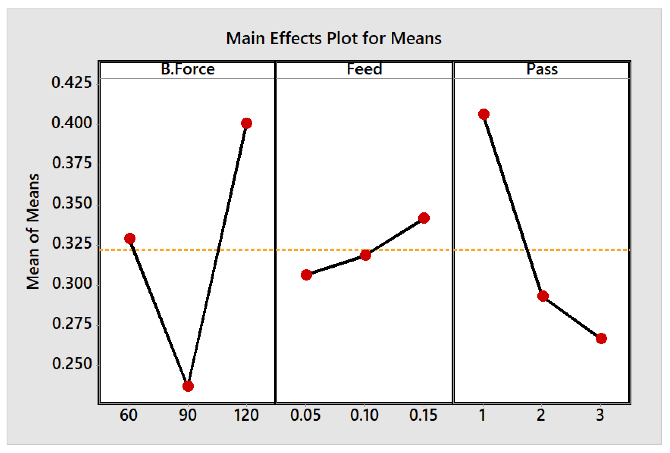
The best factor levels of the experiments are shown in the main effect plot for means and S/N ratios in
Figure 4 and
Figure 5 generated based on the smaller the better Taguchi principle. From these two pictures, burnishing force at the second level, feed at the first level, and number of passes at the third level are the best or give the smallest surface roughness values. These best parameter levels are indicated by the minimum part of the line in the main effect plot for the means graph and by the maximum part of the line in the main effect plot for S/N ratios graph.
As mentioned in the methodology part of the document, the burnishing speed was kept constant, and the other three main burnishing parameters were changed in three levels. From the ANOVA
Table 5, the feed has the least effect when compared with the number of passes and burnishing force. To further check the changing trend of surface roughness with respect to feed, burnishing force, and the number of passes, pictures are given below (
Figure 6).
In
Figure 6a, surface roughness and feed have no strong relationship in which its value decreases then increases when the burnishing forces are 60 N and 90 N, and feed is increased from 0.05 mm to 0.15 mm. However, it increased when the feed changed from 0.05 mm to 0.1 mm and then decreased when the feed was increased from 0.1 mm to 0.15 mm. However, when we observe the Ra value in
Figure 6b,c, it has an almost similar trend when the burnishing force and number of passes change at specific passes and force, respectively. It showed a decreasing characteristic in increasing the force from 60 N to 90 N and a sharp increase when further increased from 90 N to 120 N. 90 N force gave minimum roughness (0.184 µm) when the maximum number of passes (3) and 0.1 mm feed were used. As a principle, the optimum parameters level must be used to give the targeted roughness values. If the burnishing force is too low, the burnishing tool will not achieve enough force to plastically deform the peaks of the surface to the valley. The contrary is true if an exaggerated amount of force is used, which creates its own valley that can roughen the surface. In this case, 60 N and 120 N force levels gave poor surface roughness compared with 90 N force.
When we observe the results from a number of passes perspective, decreased surface roughness values are shown in
Figure 6c. At almost all force levels, the Ra values decreased on increasing the number of passes, except at the 60 N burnishing force level when increased from 2 to 3 number of passes. Even though the roughness values decreased significantly with increasing the number of passes,
Figure 7 shows that the 90 N burnishing force gave the best decrease than 60 N and 90 N consecutively. Peaks may not be deformed to the valleys at one pass, and to avoid this situation, the burnishing tool can repeat the process two or three times, depending on the experiment design. As mentioned already, almost all our number of passes levels showed a decreased surface roughness. However, this cannot guarantee to keep increasing it, as the type of product material and burnishing tool material has limitations, otherwise the surface can be damaged.
A 2D polynomial surface of the result was fitted and presented in
Figure 7 to see the effect of the parameters in a 3D graph, which is easy to understand the situation. From the used burnishing force levels, a medium amount of burnishing force and the maximum number of passes gave the best surface finish.
A burnishing process as a postmachining method was expected to modify the surface integrity of the product. Our result showed a significant decrease in surface roughness by 80% when compared with the average surface roughness value of the milled surface. Preburnishing machining process milling, in this case, played an important role in the final surface finish result. The author’s previous work had a rougher milled surface, which affected the final burnished surface roughness [
33].


