Article

Effect of Post-Processing Treatment on Fatigue Performance of Ti6Al4V Alloy Manufactured by Laser Powder Bed Fusion

by
Ane Miren Mancisidor
1,*,
María Belén García-Blanco
2,
Iban Quintana
3,
Pedro José Arrazola
4,
Elixabete Espinosa
2,
Mikel Cuesta
4,
Joseba Albizuri
5 and
Fermin Garciandia
1
1
Lortek, Basque Research and Technology Alliance (BRTA), Arranomendia Kalea 4A, 20240 Ordizia, Gipuzkoa, Spain
2
Cidetec, Basque Research and Technology Alliance (BRTA), Po. Miramón 196, 20014 Donostia-San Sebastián, Gipuzkoa, Spain
3
Tekniker, Basque Research and Technology Alliance (BRTA), C/Iñaki Goenaga, 5, 20600 Eibar, Gipuzkoa, Spain
4
Faculty of Engineering, Mondragon Unibertsitatea, Loramendi 4, 20500 Arrasate-Mondragon, Gipuzkoa, Spain
5
Faculty of Engineering, Department of Mechanical Engineering, University of the Basque Country UPV/EHU, Plaza Ingeniero Torres Quevedo 1, 48013 Bilbao, Bizkaia, Spain
*
Author to whom correspondence should be addressed.
J. Manuf. Mater. Process. 2023, 7(4), 119; https://doi.org/10.3390/jmmp7040119
Submission received: 14 May 2023 / Revised: 9 June 2023 / Accepted: 16 June 2023 / Published: 22 June 2023
(This article belongs to the Special Issue Fatigue and Fracture Mechanics in Additive Manufacturing)

Abstract

:
Fatigue properties of parts are of particular concern for safety-critical structures. It is well-known that discontinuities in shape or non-uniformities in materials are frequently a potential nucleus of fatigue failure. This is especially crucial for the Ti6Al4V alloy, which presents high susceptibility to the notch effect. This study investigates how post-processing treatments affect the mechanical performance of Ti6Al4V samples manufactured by laser powder bed fusion technology. All the fatigue samples were subjected to a HIP cycle and post-processed by machining and using combinations of alternative mechanical and electrochemical surface treatments. The relationship between surface properties such as roughness, topography and residual stresses with fatigue performance was assessed. Compressive residual stresses were introduced in all surface-treated samples, and after tribofinishing, roughness was reduced to 0.31 ± 0.10 µm, which was found to be the most critical factor. Fractures occurred on the surface as HIP removed critical internal defects. The irregularities found in the form of cavities or pits were stress concentrators that initiated cracks. It was concluded that machined surfaces presented a fatigue behavior comparable to wrought material, offering a fatigue limit superior to 450 MPa. Additionally, alternative surface treatments showed a fatigue behavior equivalent to the casting material.

1. Introduction

Additive manufacturing (AM) has strongly emerged in recent years as a disruptive technology. It comprises a set of different processes which share a common idiosyncrasy, the shaping of physical components directly from digital data by the controlled deposition of material in a layer-by-layer fashion. Due to its additive nature, AM technologies entail the following main benefits: maximum material resource efficiency, almost unlimited design complexity, maximum flexibility and customization possibilities in short development times.
Ti6Al4V is by far the metal alloy that has been more largely studied in AM applications. There are hundreds of remarkable scientific references about the manufacturing of Ti6Al4V by both directed energy deposition and powder bed fusion technologies [1]. This extended predilection for the development of AM of the Ti6Al4V alloy is due to its outstanding combination of physical properties including high strength, low density, high corrosion resistance and good biocompatibility, being the preferred material for aerospace and biomedical applications [2]. In addition, it supposes a high added value in the aerospace and biomedical sectors.
Despite the significant potential advantages of AM, a primary concern for any structural application is to ensure the repeatability and reliability of mechanical performance. According to reported data, static mechanical properties (yield stress, ultimate strength and elongation) of AM Ti6Al4V parts are comparable to wrought counterparts.
With respect to fatigue performance, which is a primary concern for commercial aerospace structures, it has been found that AM titanium materials can be comparable to wrought materials [3], but are highly susceptible to issues associated with AM, such as defects, residual stress, build orientation and surface condition. Pores, lack of fusion or cracks can act as potential stress raisers, leading to premature failure under fatigue loading [4]. Defects which are located close to the surface are especially critical [5]. In this respect, Leuders et al. [6] concluded that residual porosity has a direct effect on fatigue behavior. Additionally, surface roughness provides stress concentrations in their surroundings and can cause crack initiation, although keeping the internal defects to a minimum [7].
Centered in the laser powder bed fusion (L-PBF) process, the high cooling rates inherent in the process may cause residual stresses in the manufactured parts. It is widely known that tensile residual stresses should be avoided in fatigue loading because they promote the initiation and propagation of cracks [8].
It is essential to tackle in conjunction all the issues mentioned that have a negative impact on fatigue behavior, so that strategies that minimize defects, improve surface quality and reduce residual stresses are applied. Strategies that only improve partially the fatigue-influencing issues will not induce a sufficient benefit in fatigue response [9]. For instance, parts manufactured by L-PBF are subjected to stress relief heat treatments in order to remove residual stresses. Nevertheless, as demonstrated by [10], scattering of results can be achieved in fatigue testing due to the presence of pores which accelerate the crack growth. An effective strategy to reduce or even close residual defects remaining from the AM process is hot isostatic pressing (HIP). HIP has a direct influence on the removal of internal defects and residual stresses and on the modification of the microstructure towards a more ductile material leading to improved fatigue behavior, while the surface condition remains unchanged [11,12,13,14]. Nonetheless, at the same time, it is imperative to improve surface quality by reducing the roughness of AM parts [15]. Roughness has been verified to be the most crucial parameter in fatigue, more than the presence of defects, residual stresses or microstructure. According to [16], HIPed samples did not show significant improvements in fatigue life with rough as-built surfaces. Fatigue behavior was dominated by the rough surface rather than by internal defects of the material.
Machining is one of the most common treatments for surface modification of AM parts and leads to the highest fatigue strength if combined with HIP treatment [17]. As explained by Kahlin [16], the fracture mechanism is changed in machined samples with respect to as-built rough ones. Cracks initiate in the interior or subsurface of machined samples, whereas cracks occur on the surface of as-built parts. It is worth noting that as-built and machined samples can show a similar response to fatigue [18], despite having reduced roughness, in the presence of a high amount of internal defects. In fact, these internal defects become subsurface defects because they appear on the surface during machining. Keeping low levels of internal defects, Xu et al. [19] evidenced that machining improves fatigue strength because it eliminates surface porosity.
Nevertheless, surface quality improvement by the reduction in roughness should be addressed by other methods rather than by machining. The complexity of AM parts is very high, so in most cases, not all surfaces are accessible for machining [20]. Unfortunately, most of the investigated alternative surface treatments are not suitable for complex parts. Among the different surface treatments, shot peening has been the most extended method applied to AM Ti6Al4V parts. Although it is not very suitable for inaccessible surfaces, it improves fatigue strength and fatigue life by reducing roughness and by introducing compressive residual stresses which prevent the initiation of fatigue failure [21]. Other variants of shot peening such as laser peening and cavitation peening act in a similar way but with enhanced fatigue properties [22].
Yan et al. [23] supported that additional methods based on ultrasounds, such as ultrasonic impact treatment, ultrasonic surface mechanical attrition and ultrasonic nanocrystal surface modification, induce a plastic deformation which results in residual compressive stresses, favoring fatigue life. They indicated that the disadvantage of ultrasonic nanocrystal surface modification is that it is not applicable to complex geometries. The experiments conducted by [24] showed that the ultrasonic impact treatment distributes residual stresses and generates a hardened surface. Additionally, it is able to close surface porosity and reduce roughness. All these facts improve fatigue properties.
A non-contact surface finishing is called extreme isotropic superfinishing (ISF). It is a chemically accelerated vibratory finishing that is based on the chemical conversion of a thin surface layer that is subsequently removed by contact with vibrating, non-abrasive media. Witkin et al. [25] applied this surface treatment to Ti6Al4V parts manufactured by L-PBF technology. High cycle fatigue properties were improved with respect to non-treated samples. According to these authors, the improvement is based on the reduction in surface roughness rather than residual stress modifications. The overall surface roughness is improved and sharp crack-like features are expanded and rounded, avoiding the formation of fatigue cracks.
As-built surface quality can be also improved by more conventional strategies such as sandblasting, tribofinishing and chemical and electrochemical polishing, which are more economical and easily industrialized compared to the previously mentioned ones. For instance, sandblasting is the most used process to reduce the surface vast roughness of L-PBF parts and it is appropriate to remove adhered powder particles. Although a waved surface is achieved, sandblasting can improve fatigue properties compared to as-built conditions [26]. Within chemical treatments, chemical etching is able to eliminate defective layers and adhered particles, improving fatigue strength [14]. Electropolishing can produce bright surfaces with smoothed high points and low regions with a pooled look. It has been demonstrated that the application of electropolishing after a mechanical treatment such as shot peening could reduce the surface roughness by more than half and provide significant improvements in fatigue resistance, especially for high cycle fatigue regimes [27].
Finally, we can mention the tribofinishing method to smooth surfaces, during which the parts are vibrated in a tank with abrasives. In [9], L-PBF Ti6Al4V parts were tribofinished after performing a stress relief heat treatment and HIPing. They achieved fatigue limits of 325 MPa for stress-relieved parts and 350 MPa for HIPed samples.
In conclusion, focusing on surface finishing methods for Ti6Al4V processed by AM, machining is the option that results in the highest fatigue strength and fatigue life, obtaining values comparable to conventional wrought material. The vast majority of surface treatments do not have such a large impact on fatigue properties, and the most studied ones do not imply conventional surface technologies which, in the end, are more economical and could be more easily managed by AM part manufacturers. Moreover, the fatigue properties of Ti6Al4V alloys processed by L-PBF technology and post-processed with conventional mechanical and electrochemical technologies have not been previously compared among them and with the machining process. Therefore, this study focused on the analysis of the effect of conventional surface modification approaches such as tribofinishing, sandblasting and electropolishing applied after sandblasting (E-Blasting process) on the surface roughness reduction, residual stress and fatigue behavior of a Ti6Al4V alloy produced by L-PBF. The obtained results were compared with samples with machined surfaces and conventionally cast and wrought Ti6Al4V materials.

2. Materials and Methods

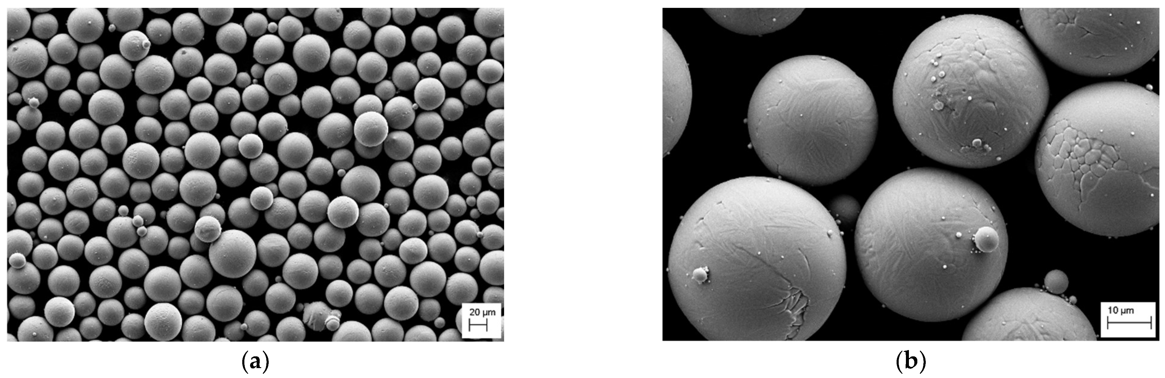
2.1. Powder Bed Sample Fabrication

All the test samples were produced using Grade 23 Ti6Al4V powder provided by Carpenter Technology. This powder, atomized in an argon atmosphere, had a particle size range from 20 to 63 µm with an average particle size of 37 µm. LECO analysis revealed an oxygen level of 0.086% in the as-received condition. Figure 1 shows the spherical morphology of the powder employed in this study which assured good flowability.
The MCP Realizer 250 L-PBF system, supplied by MTT Group (Stone, Kent, UK), was employed to build the test samples. This machine was fitted with an IPG fiber laser (Ytterbium laser in solid state) from IPG Photonics manufacturer (Oxford, UK) with a wavelength between 1085 and 1090 nm and a maximum power of 200 W. The manufacturing was carried out in an argon protective atmosphere. The platform was heated to 200 °C. Optimized process parameters were used to guarantee a density superior to 99.9%.

2.2. Post-Processing of Testing Samples

The manufactured samples were subjected to a hot isostatic pressing (HIP) cycle to remove possible remaining residual defects. Samples were HIPed at 920 °C and 100 MPa for 2 h under an argon gas atmosphere. HIP treatments were performed by Bodycote SAS European Group. Additionally, a conventional heat treatment was conducted on some of the fatigue samples. This cycle consisted of heating the samples to 850 °C in vacuum for 5 h.
Various surface modification methods (sandblasting, electropolishing and tribofinishing) were then applied to hipped fatigue samples in order to evaluate their influence on fatigue performance. In addition, the combined effect of sandblasting and electropolishing was also assessed. This surface treatment was labeled as E-Blasting. For the sake of comparison, the surfaces of a number of fatigue samples were machined. Only the length of the gauge area of fatigue samples was post-processed with the above-mentioned methods. All the heads were machined to assure correct clamping during fatigue tests.

2.2.1. Sand Blasting

Samples were blasted using corundum of 90–105 µm (angular shape) with a pressure drop across the nozzle of 5.5 MPa, at a 4 cm distance from the nozzle to the part, for 4 min.

2.2.2. E-Blasting

E-Blasting was carried out by combining the described sandblasting process and an electropolishing treatment that was carried out at 30 °C, at a constant voltage (38 V) for 20 min. The electropolishing electrolyte was a non-aqueous one, comprising ethyl alcohol (700 mL L−1), isopropyl alcohol (300 mL L−1), AlCl3 (60 g L−1) and ZnCl2 (250 g L−1). A two-electrode system was used, with the anode being the Ti6Al4V fatigue sample and the cathode being a circular Cp Ti mesh.

2.2.3. Tribofinishing

The parts were vibrated using two different types of routes (Table 1). The process parameters that were modified to study their influence on the final roughness (and therefore on the fatigue life of the parts) are described below. Three aspects were modified as input parameters: abrasive chip (M), chemical product (Q) and time (T).
1.
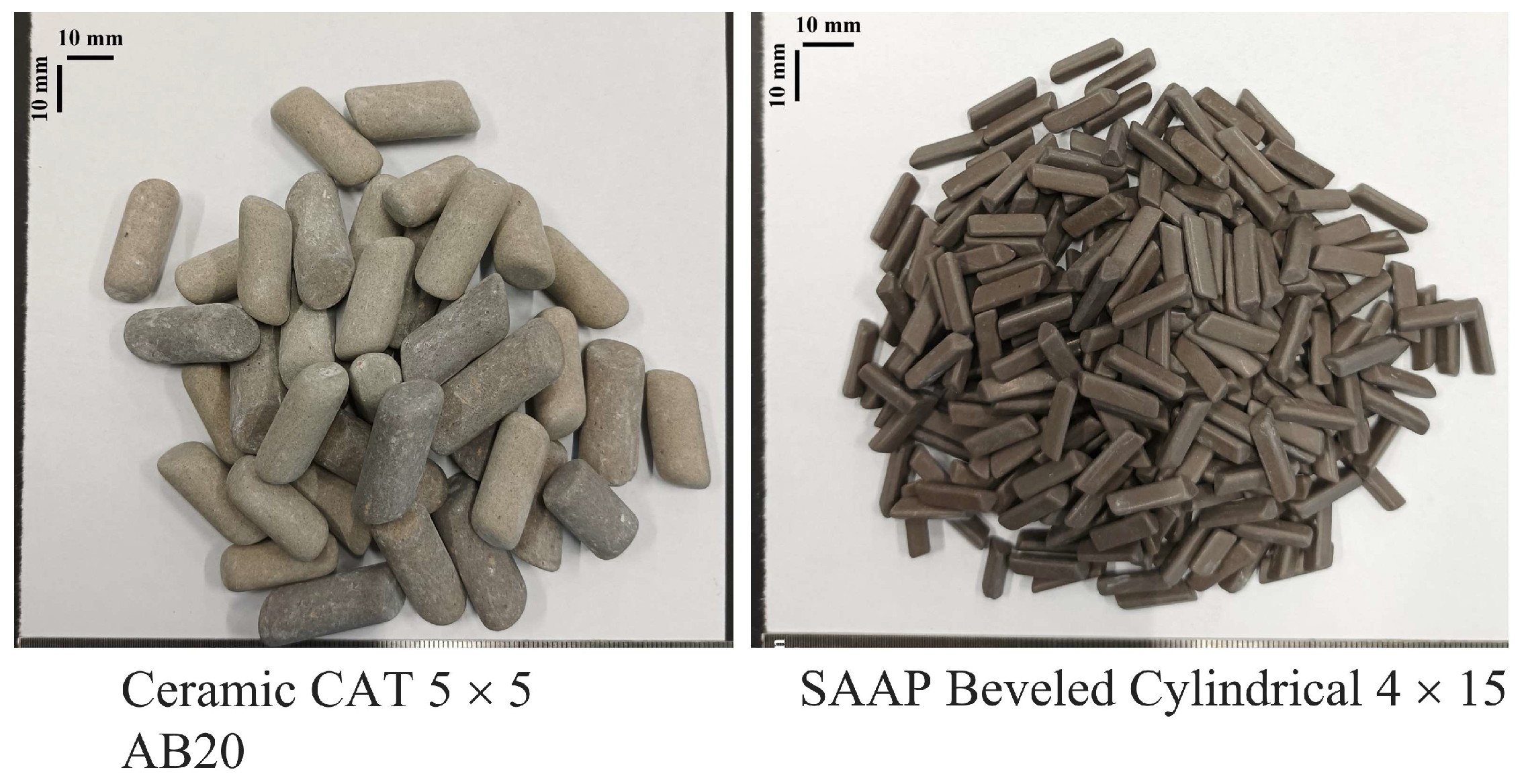
Abrasive chip (M) (Figure 2).
  • Abrasive 1: SAAP Cylindrical Chamfered 4 × 10;
  • Abrasive 2: Ceramic CAT 5 × 5 AB20.
2.
Chemical product (Q).
  • Chemical product 1: METALENE TPR 3%;
  • Chemical product 2: METALENE Beta 2%.
3.
Time (T).
The chemical product used was composed of a mixture of soaps, antioxidants, brighteners and specific additives provided by the company responsible for supplying the different products necessary for the tribofinishing process (self-formulation).

2.2.4. Machining

Samples were machined by turning and polishing to a final surface roughness of 0.4 µm Ra.

2.3. Testing of Samples

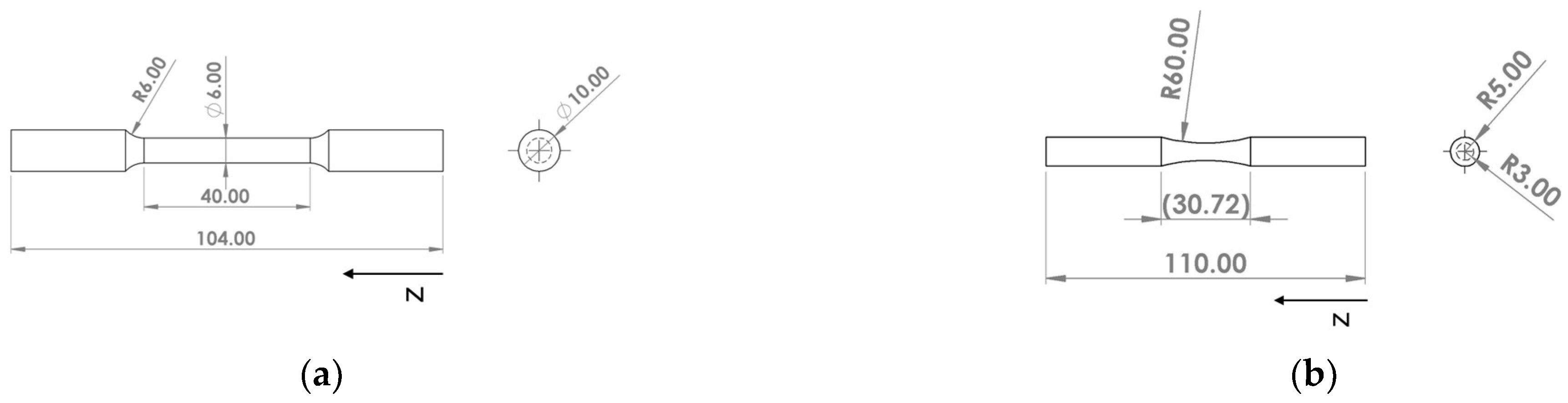
2.3.1. Tensile Testing

Cylindrical dog-bone-shaped samples (Figure 3a) were manufactured in the vertical direction (parallel to the building direction (z)). Tensile testing was performed according to ASTM E8 standard at room temperature using the Zwick Roell Z100 (Barcelona, Spain) tensile testing machine with an external extensometer. Tensile samples were tested in the machined surface condition, in the as-fabricated state (without any heat treatment) and after performing the HIP treatment. Three samples per condition were tested.

2.3.2. Fatigue Testing

Fatigue samples were manufactured in the vertical direction (z). Hourglass fatigue samples were tested as specified in Figure 3b.
Rotating bending fatigue tests were carried out using a Zwick/Roell model 200TC UBM machine (Barcelona, Spain) and according to ISO 1143 (rotating bending tests). These rotating bending tests were performed in the high cycle fatigue (HCF) regime with a frequency of 100 Hz and at room temperature. A run-out of 5 × 10⁶ cycles was established.
All the samples were HIPed and subsequently subjected to the surface treatments detailed previously before performing the fatigue tests. A minimum of six samples per condition were tested. As a starting point, as-built roughness was also evaluated.

2.4. Samples Characterization

The surface roughness of the fatigue samples was measured using an Intra 50 mm (Taylor Hobson brand, Leicester, UK) profilometer. Filter parameters to calculate the roughness parameters Ra were selected according to the UNE-EN ISO 4288 standard. Surface topography was characterized using a Leica DCM 3D (Wetzlar, Germany) confocal microscope and the morphology was analyzed in each surface condition by the FE-SEM Ultra Plus scanning electron microscope from Zeiss, equipped with a compositional analysis module (EDS).
The microstructure in the as-built state and in the HIP condition was characterized in order to establish a connection with static mechanical properties. For that, samples were metallographically prepared by grinding with SiC paper and polishing to a mirror finish. Micrographs of the prepared surfaces were obtained with the same FE-SEM equipment. Moreover, density with and without HIP treatment was measured to prove the effectiveness of HIP treatment in reducing residual porosity. Relative density was determined by an optical microscope (GX51 Olympus, Hamburg, Germany) and using Image-J image analysis software.
Axial residual stresses (ARS) were analyzed by the X-ray diffraction technique (Bruker X-Ray diffractometer D8 with Cu radiation) using the sin2Ψ [28] method on the surfaces of the fatigue samples. The areas where the different post-processing methods were applied were analyzed. For the determination of the in-plane stress tensor, diffraction curves of the different α (213) phase diffraction peak between 138° < 2θ < 145° (θ is the Bragg angle) must be obtained with at least three independent rotation angles (Φ = 0°, 45° and 90°).
Finally, fracture surfaces of fatigue samples were studied using the FE-SEM Ultra Plus scanning electron microscope to assess the origin of the fracture.

3. Results

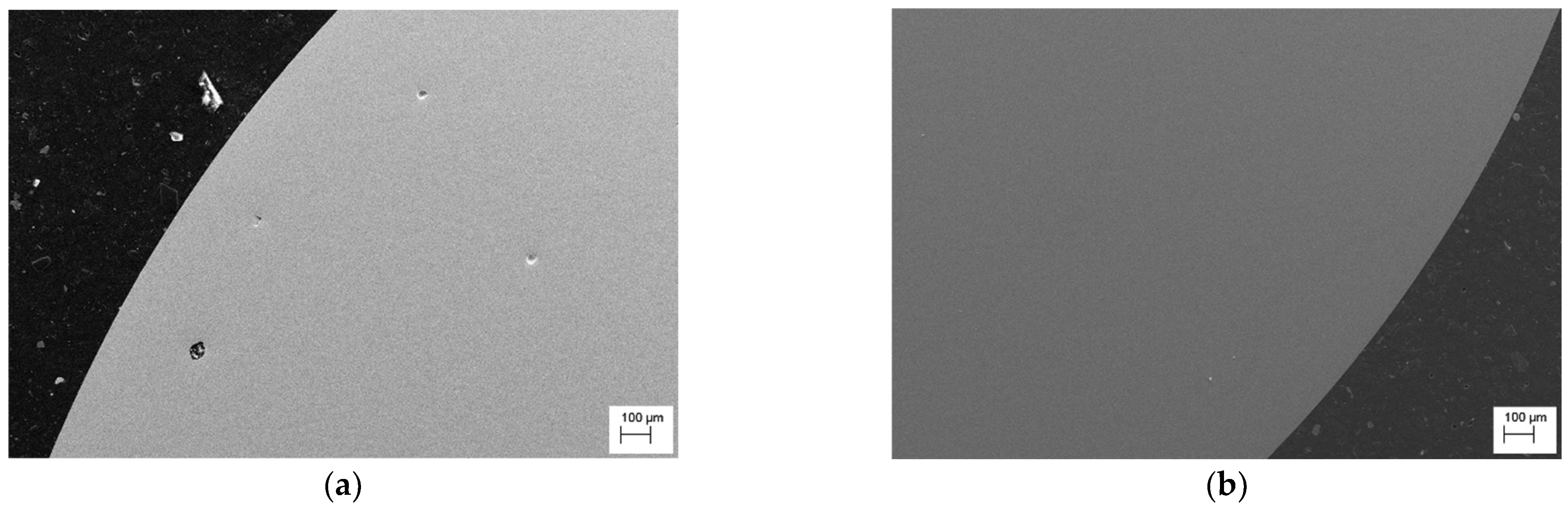
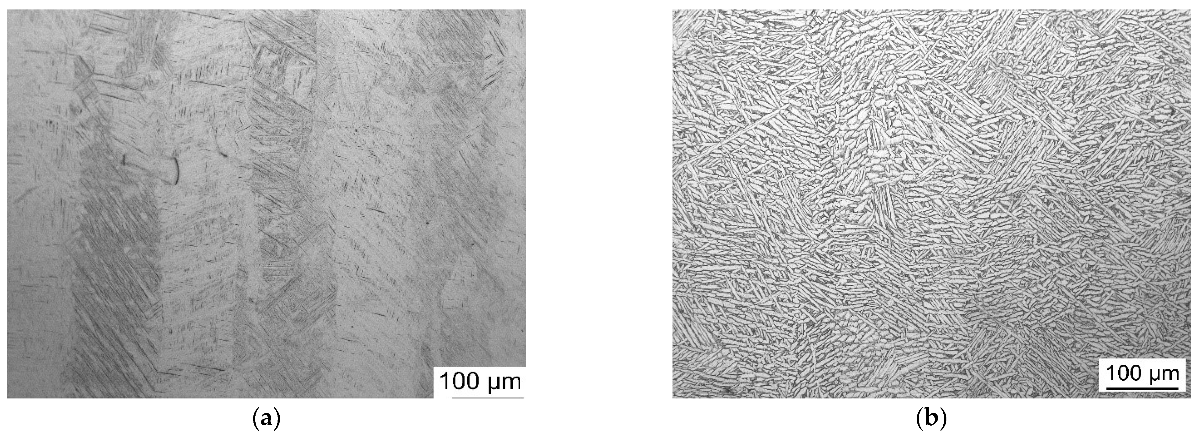
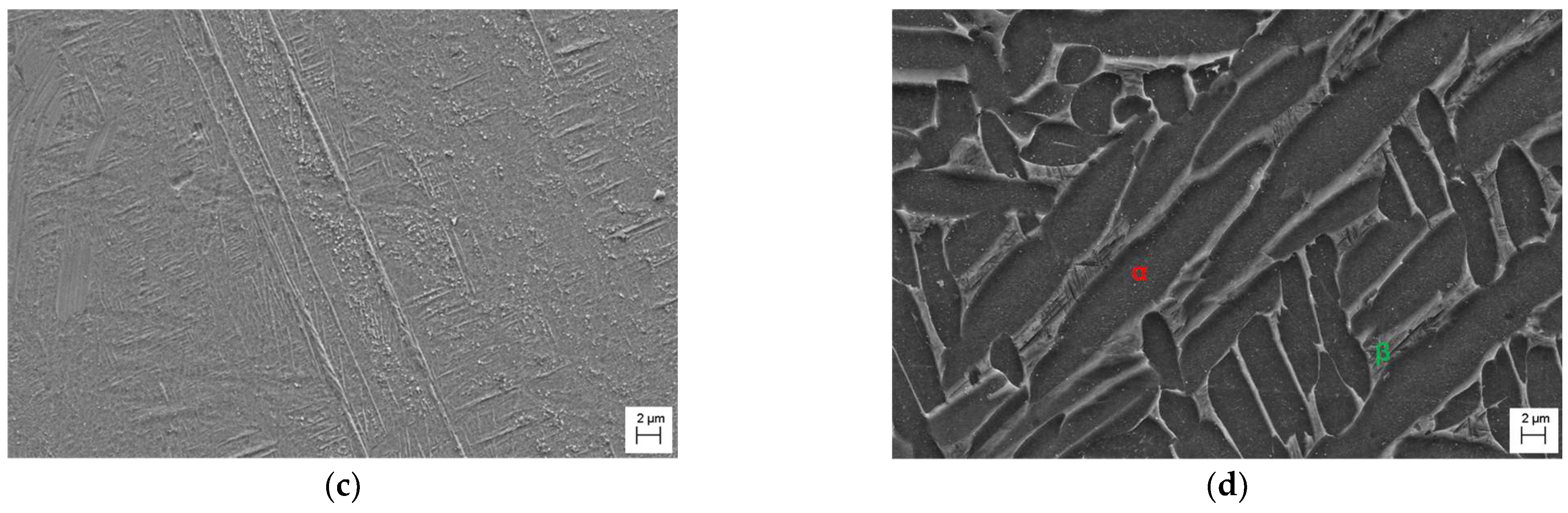
3.1. Evolution of the Microstructure

The effectiveness of the HIP treatment in removing defects of Ti6Al4V parts manufactured by the L-PBF process was first evaluated. The maximum density achieved with the optimized processing parameters was 99.90%. Therefore, residual defects were observed in as-built samples. Only spherical pores were detected, and there were no lack of fusion defects. The source of porosity could be internal porosity present in the atomized powder or gas entrapment during the manufacturing process. This residual porosity decreased significantly after performing the HIP treatment, obtaining nearly fully dense parts (99.99%). The internal quality of the parts is evidenced in the SEM images in Figure 4.
As can be presumed from Figure 5, the microstructure of Ti6Al4V can be considerably influenced when applying the HIP treatment. As a result of the L-PBF process, a fine microstructure developed in a martensitic (α’) needle shape due to the rapid fusion and posterior solidification (Figure 5a,c). However, after the HIP thermal treatment at 920 °C, below the β transus (955 °C) temperature, the fine martensitic microstructure transformed into a mixture of α and β phases, where the α phase presents as fine plates (Figure 5b,d). HIP treatment also induced a coarsening of the microstructure compared to the original α’.

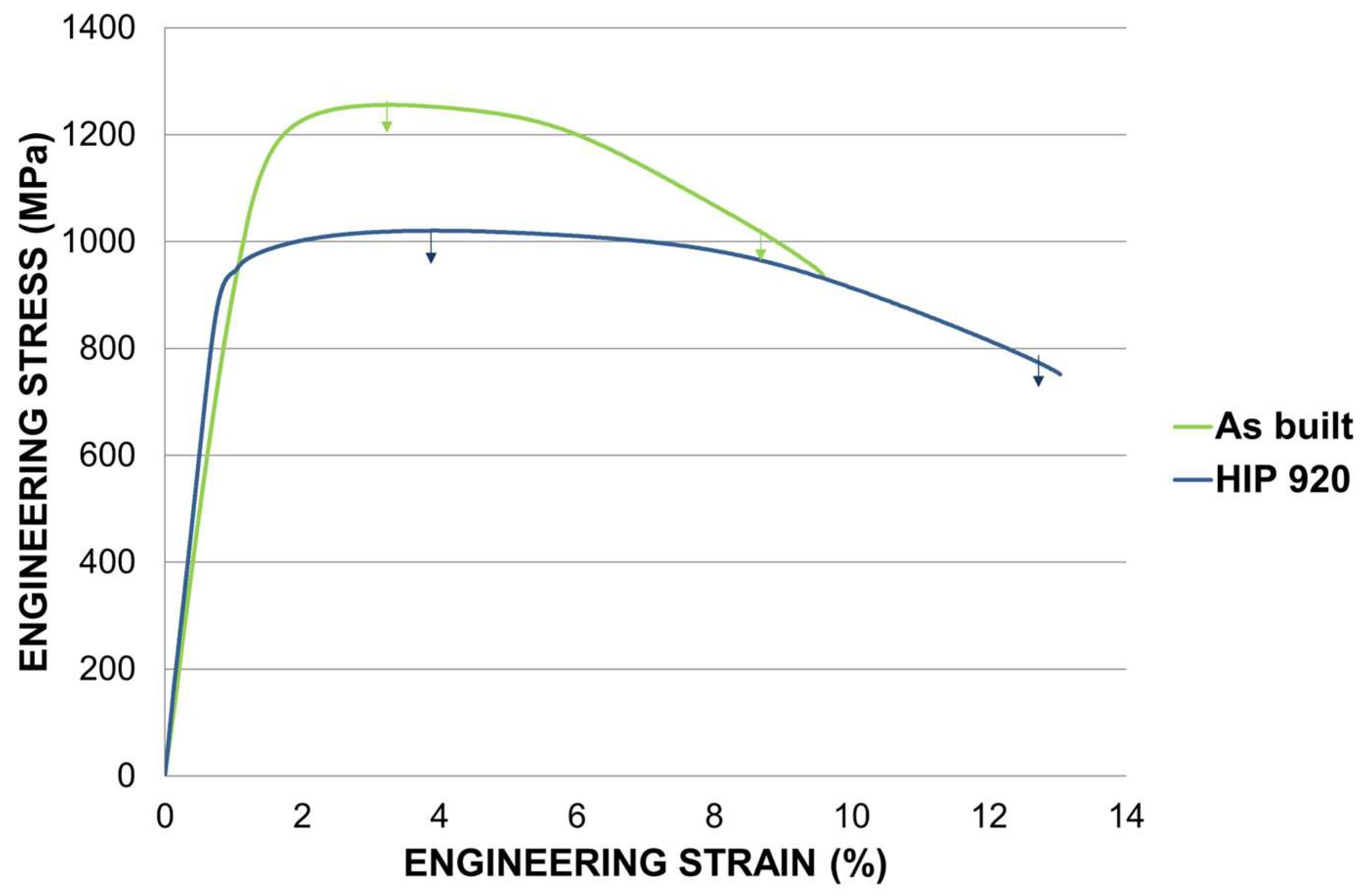
3.2. Static Mechanical Properties

Engineering stress–strain curves and resulting tensile properties are shown in Figure 6 and Table 2, respectively, for as-built and HIPed Ti6Al4V samples. The highest mechanical strength was obtained for samples in the as-built condition, reaching approximately 1260 MPa. Following HIP treatment, the strength was reduced to around 942 MPa. Concerning ductility, as-built parts had a low elongation at failure of about 8.5%. This value could be increased up to 12.5% with the HIP cycle. Consequently, HIP treatment favors the ductility of titanium parts manufactured by L-PBF.

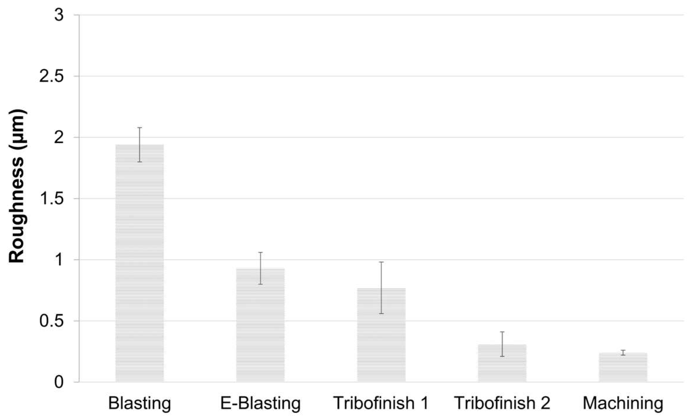
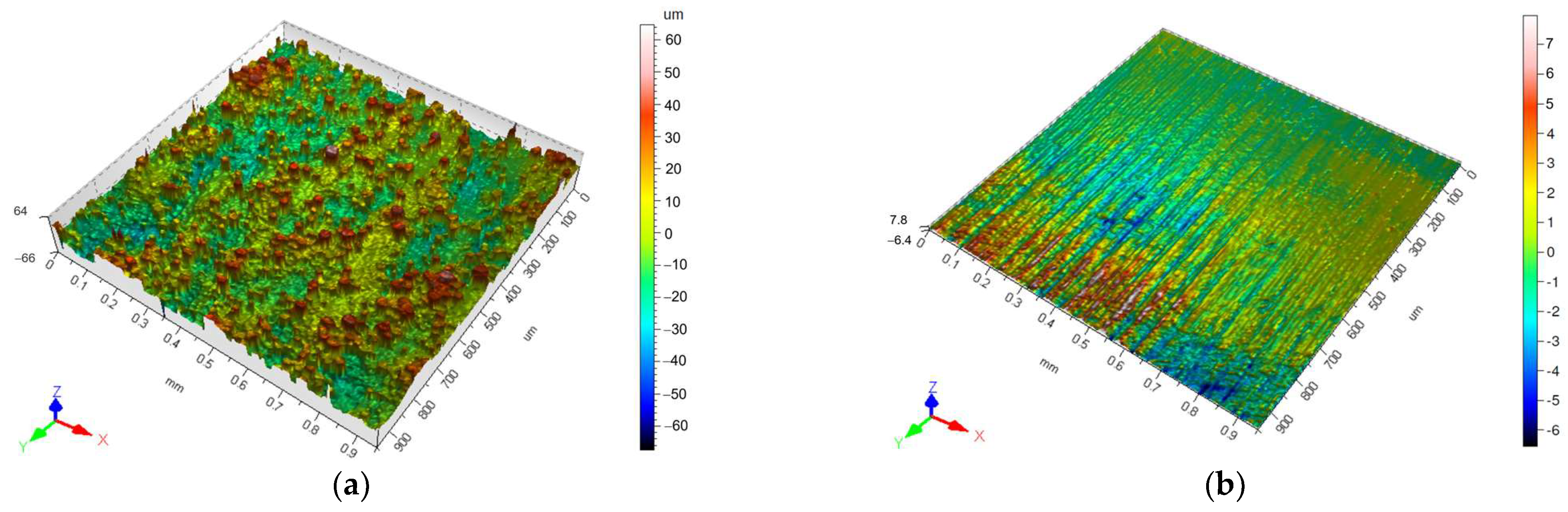
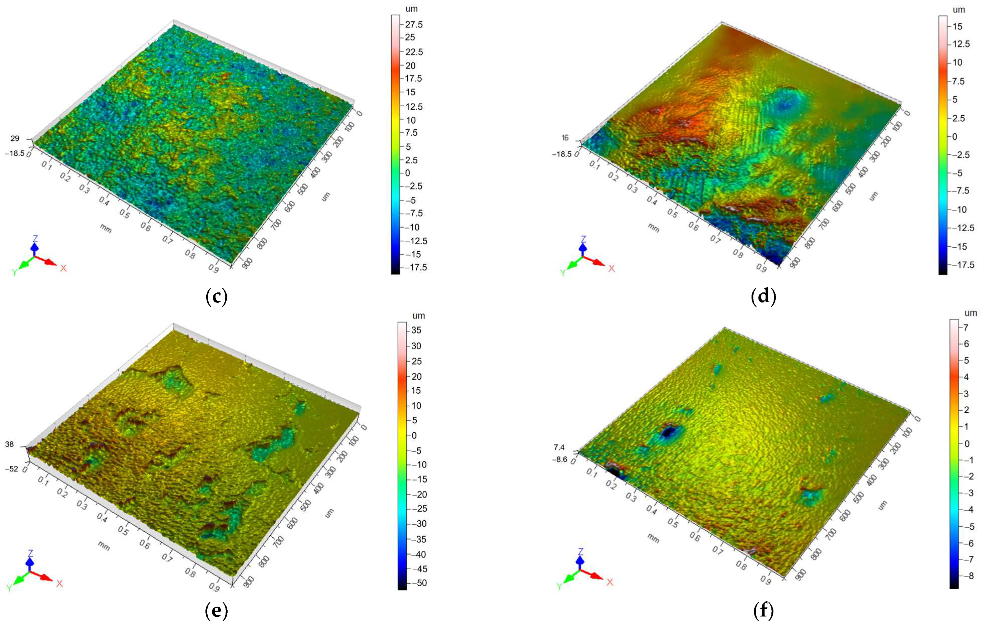
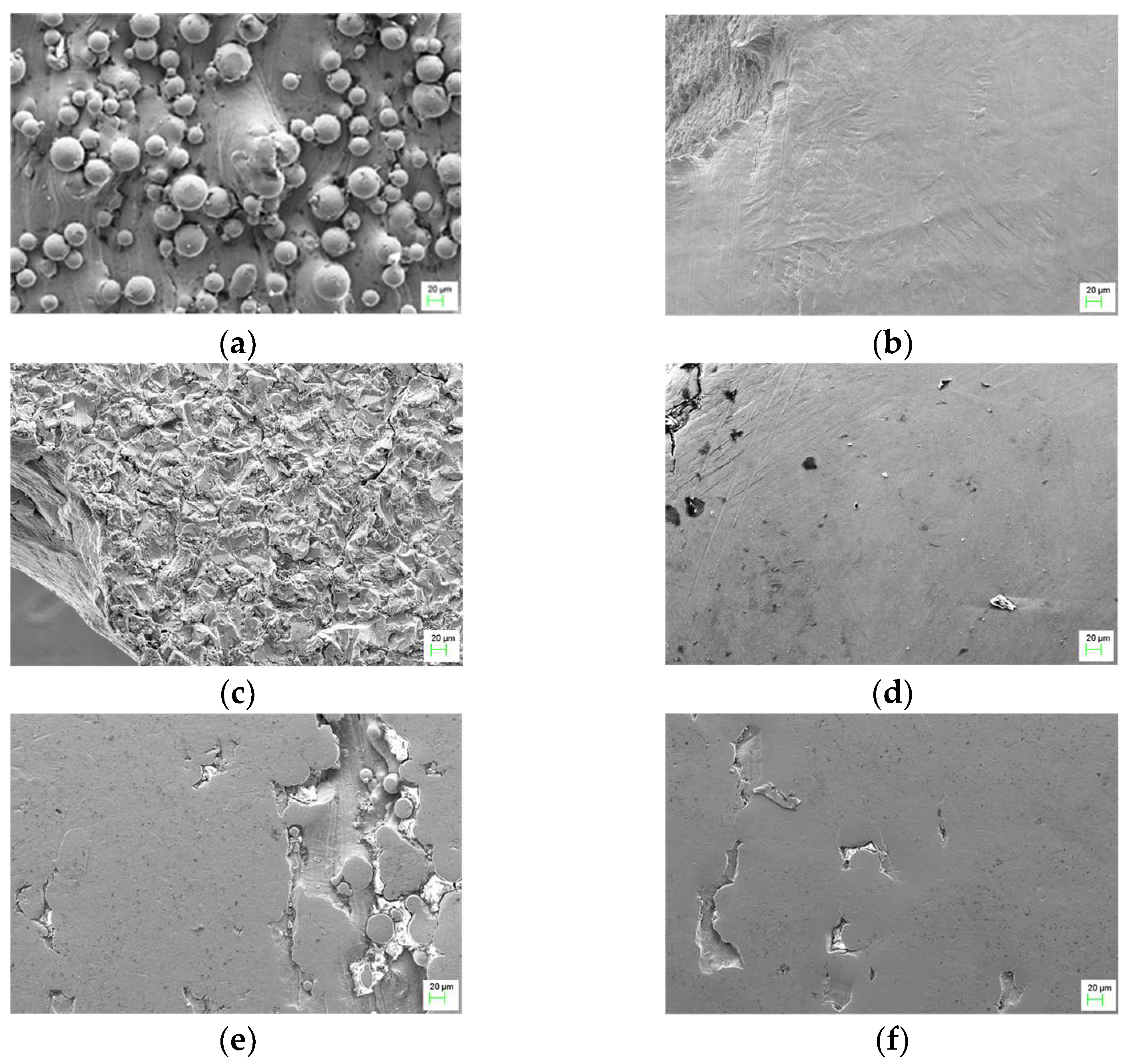
3.3. Surface Treatment of Fatigue Samples

The roughness of the as-built surface was measured before the application of the different surface treatments. Ra (the average roughness of the surface) was 8.3 ± 0.9 µm. Figure 7 shows roughness values measured on post-processed surfaces after the diverse surface modification methods. Comparing the roughness of as-built samples with the ones obtained with any of the surface treatments, it can be observed that this value was considerably reduced. Among post-processing treatments, blasting modification gave rise to the roughest surface, achieving Ra of 1.94 ± 0.14 µm. Subsequent electropolishing improved the surface condition, reducing the roughness down to 1 µm (0.93 ± 0.13 µm). In the case of the tribofinishing surface treatment, both conditions led to roughness values below 1 µm. Optimizing tribofinishing conditions, roughness was decreased by half, from 0.77 ± 0.21 µm to 0.31 ± 0.10 µm. Finally, the machined surface was quite similar to that obtained with the tribofinishing method using optimized conditions. However, the roughness is more homogeneous and the observed deviation is smaller.
In Figure 8 and Figure 9, the topography of the surfaces in each condition is detailed. As-fabricated parts exhibited partially melted particles on the surface (a), being responsible for the resultant rough surface. The surface topography of the samples treated with the applied methods was transformed significantly. Machined surfaces (b) look smooth, although some machining parallel marks can be seen by confocal microscopy. With blasting (c) and E-Blasting (d), the partially melted powder particles were removed completely. However, the surface treatment with the blasting method displayed peaks and valleys, whereas the E-Blasted samples showed a smoother and brighter appearance. As is evident in (e), the conditions first tried in the tribofinishing technique were not able to totally eliminate the partially melted particles, and important cavities were left on the surface. Increasing the time of the process, no partially melted particles were observed, but still, some residual cavities were detected (f).
Residual stress analyses were performed on the surfaces of samples with and without surface treatments. It must be noted that residual stresses were measured after subjecting the samples to the HIP treatment. The measurement results are given in Figure 10. Without surface treatment, that is, in the as-HIPed state, tensile stresses were apparent. After surface-treating the samples, tensile stresses were converted into compressive residual stresses, irrespective of the type of surface modification technique employed. The highest compressive residual stresses were measured for the blasted and optimized tribofinished treatments, followed by machined samples and tribofinishing applied with the initial processing conditions. It was also observed that electropolishing reduces the level of residual compressive stresses in comparison with the blasted samples. In fact, the E-Blasted sample is the one with the lowest residual compressive stress, approaching zero.

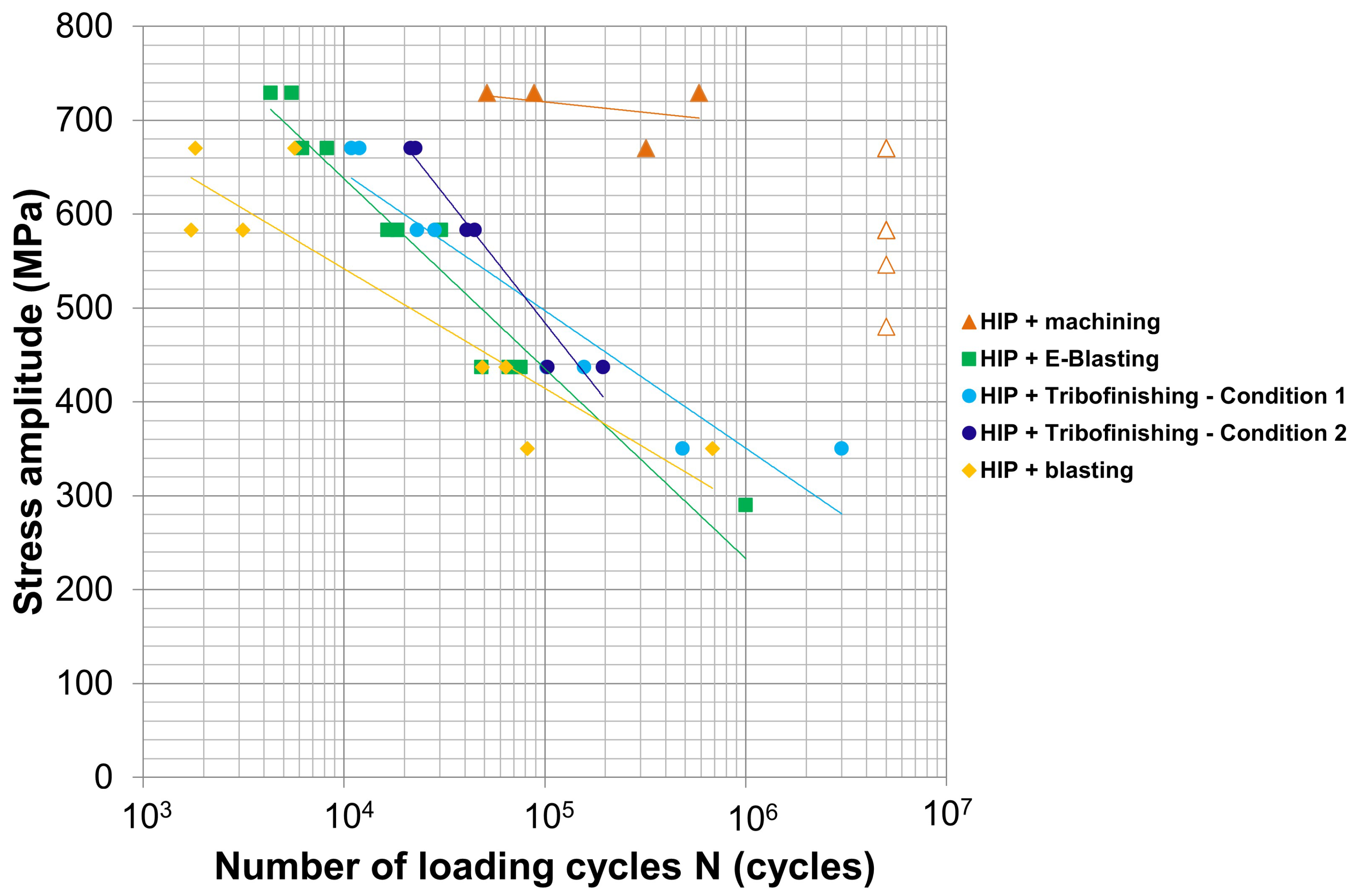
3.4. Fatigue Behavior of Surface-Treated Samples

Fatigue testing was performed on samples subjected to HIP treatment and surface treatment with different techniques in order to analyze the effect of the surface condition on fatigue response and reduce any effect of internal defects as much as possible. As revealed in the investigation carried out by [7], the as-built rough condition is detrimental to fatigue strength. Vayssette et al. [29] also achieved an improved fatigue limit after machining samples manufactured by L-PBF. The fatigue strength increased from 222.5 MPa to 512.5 MPa due to the removal of attached powder particles and smoothing of the surface. As a first study, a fatigue test was performed in the as-built surface state and compared with the machined sample. As indicated in Table 3, the as-built sample was heat-treated at 850 °C to transform the microstructure into a more ductile arrangement composed of α + β phases. Additionally, one machined sample was heat-treated in the same conditions and the other was HIPed for the sake of comparison. It was demonstrated that the sample with the as-built rough surface only lasted around 14,000 cycles. The behavior was improved by machining the samples. Sample 2 with the conventional heat treatment survived more than 3 million cycles, whereas the sample with HIP reached the run-out at 5 million cycles.
The subsequent fatigue tests were executed in the HIPed condition and surface treatment with blasting, E-Blasting, tribofinishing (initial parameters (condition 1) and optimized parameters (condition 2)) and machining. The results are shown in Figure 11. The best fatigue performance was achieved for the machined surface condition, with a fatigue limit higher than 480 MPa. The empty symbols indicate that the samples reached the run-out. It is worth noting that at loads where the run-out was achieved without failure, this involved the testing of several samples. More concretely, at 480 MPa, 6 samples were confirmed to reach more than 5 million cycles, 3 at 583 MPa and 2 at 670 MPa. On the contrary, blasted samples exhibited the worst fatigue results. The number of cycles withstood was lower than the E-Blasting surface method. Therefore, electropolishing-blasted surfaces improved the fatigue behavior of Ti6Al4V samples. On the other hand, tribofinishing slightly enhanced the fatigue performance compared with E-Blasting. That is, employing the same load, samples broke after a higher number of cycles. Moreover, fatigue behavior was superior when optimized parameters were used to finish the samples with the tribofinishing technique.

4. Discussion

4.1. Effect of HIP on Densification, Microstructure and Mechanical Properties

The use of optimum L-PBF processing parameters led to densities up to 99.9% in the as-fabricated state with minimal presence of pores. Although in principle, this level of density could be acceptable from an internal quality point of view, it has been demonstrated that HIP has a relevant role.
Samples with HIP were almost free of defects. Consequently, the number of stress concentration points was much lower, reducing fatigue crack initiation sites. This fact is of utmost importance, as it is appreciated in the fracture surfaces of fatigue samples (Figure 12). The rough surface achieved in the as-built condition was responsible for the low number of cycles withstood by samples with conventional heat treatment. Sintered particles were evident in the fracture surface of fatigue samples (Figure 12a), increasing the roughness and making them sensitive to premature fracture. Ref. [30] attributed the poor fatigue limit (210 MPa) of Ti6Al4V processed by L-PBF to the poor surface quality (13 µm Ra) of the as-built samples. Cracks initiated at the rough surface and propagated inwards, causing fractures. Although removing these particles by machining enhanced the surface quality considerably, the fatigue response was not the highest. Spherical pores were concentrated in the subsurface region (Figure 12b), which is more critical for fatigue life. The research carried out by [6] demonstrated that stress concentrations at defects reduce the fatigue strength of Ti6Al4V produced by L-PBD. In particular, the samples containing pores near the surface broke in the early stages. Likewise, Kempen et al. [31] supported the same finding for aluminum samples built with the same technology. In order to improve fatigue behavior, it was necessary to have high surface quality with reduced roughness and porosity. This was the case for samples subjected to the HIP cycle (Figure 12c). With the purpose of having consistent results, additional conventionally treated fatigue samples were tested with the machined surface, obtaining very dissimilar values, from around 35,000 to more than 3 million cycles. The occurrence of internal and especially subsurface porosity causes the dispersion in fatigue results. This dispersion was avoided by applying the HIP heat treatment. Similar dispersion in fatigue results was achieved by Benedetti et al. in stress-relieved Ti6Al4V samples built by L-PBF [9]. Thus, it has been demonstrated that the level of defects present in the as-fabricated condition, although residual, is critical for fatigue.
Another benefit of HIP treatment is the increase in the ductility of the manufactured parts, which contributes positively to fatigue strength. This is corroborated by several researchers. For instance, Ref. [4] reached ductility values of up to 19% after applying HIP. The increase in ductility in combination with the reduction in the porosity level favored the fatigue behavior. Yan et al. [23] also proved the favorable effect of HIP on fatigue. As shown in Figure 6, HIP samples showed more ductile behavior. Specifically, an increment of 47% in ductility was achieved with respect to the as-built state. The increase in ductility occurred at the expense of the lower strength of HIPed samples due to the microstructure transformation induced during the heat treatment. After L-PBF manufacturing, a fine microstructure developed in a martensitic (α’) needle shape due to the rapid fusion and posterior solidification, giving rise to high strength but low ductility (8.5%). However, after the thermal treatment at 920 °C, below the β transus (955 °C) temperature, the fine martensitic microstructure transformed into a mixture of α and β phases, where the α phase is presented as fine white needles. Moreover, the microstructure is coarser than the original α’, causing a decrease in the mechanical strength and an increase in the ductility (~12%). These trends are in good agreement with the findings of [32]. As explained by Vrancken et al. [33], applying a thermal treatment, the α phase is nucleated along the α’ grain boundaries, leading to the formation of β at the α phase boundaries. At high temperatures, fewer nuclei are present and they can coarsen to a greater extent, increasing the final grain size. That is, heating below β transus, both α and β will tend to coarsen but will impede each other, limiting the grain growth. This effect diminishes as the temperature is elevated closer to β transus and α fraction decreases. The achieved mechanical properties after applying HIP are well above the specifications of the cast and forged Ti6Al4V material and comparable to those reported in the literature [14]. It is worth pointing out that the conventionally heat-treated samples at 850 °C, which showed a scattering of fatigue results, would display a similar microstructure to HIP samples, probably composed of slightly finer α and β phases due to the lower applied temperature. Thus, the poorer fatigue response can be attributed to the presence of residual defects, as explained previously.

4.2. Effect of Post-Processing Treatment on Fatigue Properties

Several surface treatments were applied to Ti6Al4V samples processed by L-PBF with the intention of improving fatigue behavior. All samples were tested in the same heat treatment condition, i.e., in HIP condition to remove internal and subsurface residual porosity. Thus, the differences observed in fatigue response (Figure 11) after the surface modification techniques could be attributed to the surface state condition (i.e., presence of surface defects, roughness, topography and residual stresses).
The fatigue behavior of as-built samples was very poor. However, regardless of the surface modification technique, surface roughness was considerably reduced compared to the as-built condition, and surface residual stresses were transformed from tensile to compressive ones. These two facts led to an enhancement in fatigue response, since even applying a conventional heat treatment, the level of porosity was low. According to several researchers, roughness was the primary reason for the low fatigue behavior. Ref. [34] associated the poor fatigue behavior of grit-blasted Ti6Al4V samples with the higher surface roughness compared to the polished ones, as grit blasting did not introduce significant compressive residual stresses. Roudnicka et al. [35] also proved that maintaining the as-built roughness, HIP was not sufficient to improve this property. Due to the complex thermal history of the L-PBF process and other associated issues, partially melted particles adhered to the surface, showing habitual high roughness [36]. According to topography images in Figure 8 and Figure 9, as-built samples exhibit plenty of adhered particles, which are responsible for the high measured roughness (8.3 ± 0.9 µm), making the surface sensitive to premature fracture [30]. The fracture surface analysis (Figure 12a) revealed that surface failure occurred at the edge of the sample, where cracks initiated at the rough surface. Note also that although they were subjected to HIP, tensile residual stresses remained in the samples (Figure 10), indicating that the heat treatment was not totally effective in removing residual stresses generated during the L-PBF process. Benedetti et al. [37] observed that tensile residual stresses were eliminated and converted to compressive residual stresses in HIPed samples in the same conditions as the current investigation. Nevertheless, they could still detect large near-zero hoop tensile residual stresses close to the surface. Higher residual tensile stresses are expected in non-heat-treated samples due to the high thermal gradients and fast solidification during the L-PBF process, which are detrimental to fatigue behavior [15].
Following blasting, compressive residual stresses are introduced, achieving high values on the surface. It has been widely proved that processes such as turning, grinding and polishing introduce compressive residual stresses. In fact, Yu et al. further increased surface compressive residual stresses by sandblasting after grinding [3]. Moreover, roughness was reduced considerably compared to the as-built state, reaching around 2 µm Ra. Nevertheless, the fatigue results are the poorest among the used surface treatment methods. The resulting peaks and valleys could have a negative impact on fatigue response. Similar surfaces were obtained in [14]; however, fatigue tests were not conducted with this surface condition. Fatigue fracture morphology (Figure 13a,b) indicates that cracks initiate from the surface most likely due to these topographic irregularities. Subsequent electropolishing of the blasted samples still maintains compressive residual stresses, although their level is reduced. Roughness is also improved slightly. Nevertheless, a marginal improvement in fatigue behavior is observed. The reason could be attributable to surface non-homogeneities. Accordingly, the surface is not totally smooth and there are some surface irregularities that could be responsible for the crack initiation.
Tribofinishing treatment is also able to introduce compressive residual stresses on the surface which are higher when optimized conditions are employed and comparable to the blasting process. However, using tribofinishing, fatigue is improved with respect to the blasting condition. The resulting surfaces are smoother than those obtained with the previously mentioned treatments, where very low roughness values are measured, especially with the optimized condition. The reduction in roughness from initial tribofinishing conditions to the optimized ones produces better fatigue properties. Possibly a greater improvement in fatigue response would be observed if surface irregularities were avoided. Numerous and large surface cavities can be found using initial conditions which are accompanied by deformed powder particles. These defects are reduced considerably when the samples are treated with optimized conditions. Again, for both tribofinishing conditions, the rupture occurs on the surface (Figure 13f−i). Similar cavities were found in [14] but after subjecting the samples to wet polishing. The fatigue results are superior to those obtained with tribofinishing. Nevertheless, the distribution and number of cavities remain unknown or are not specified by the authors. Additionally, there is a lack of information regarding residual stresses.
The measured roughness value in machined samples is the lowest and comparable to the roughness obtained with tribofinishing in optimized conditions. The difference between these two surface finishing methods lies in the roughness homogeneity along the whole surface. Machined surfaces do not show irregularities as is the case for tribofinishing. This fact is also demonstrated by the much smaller deviation observed in roughness measurements (Figure 7) for machined samples. Machining also produces favorable compressive residual stresses, where intermediate values between the two tribofinished conditions are achieved. Consequently, machining produces the best fatigue results. The crack initiation site is located at the surface, as shown in Figure 13f. This is consistent with the conclusions extracted by [38] regarding the fracture surface analysis of samples tested below 107 cycles.
As explained previously, the fatigue crack was initiated from defects found on the samples’ surfaces regardless of the type of surface treatment applied. For instance, the cavities that originated in E-Blasted samples are stress concentrators that initiate cracks (Figure 13e). Figure 13d shows the crack initiation site (red rectangle) in addition to the fatigue crack growth direction (black arrows). Further magnification of the area around the crack initiation site (Figure 14a) reveals that the fracture is generally dominated by transgranular fracture mechanisms, where the fracture takes place through the grains. Instead, the micrograph corresponding to the area far from the crack initiation site (Figure 14b) indicates that in the last stages, the fracture occurs by intergranular mechanisms, in which the crack propagates along grain boundaries. Similar behavior was observed for the rest of the surface treatments.
Figure 15 shows a ranking of surface properties of samples with the analyzed surface treatments, constructed by different tonalities for a certain color. Within a property, the darkest tonality signifies the worst value achieved and a high (negative) impact on fatigue results. Fatigue has also been ranked using the same color code. It is evident that when roughness is reduced, fatigue is improved accordingly. Regarding topography, the smoother the surface is, the better the fatigue behavior. Additionally, it is worth remarking that surface irregularities should be avoided to benefit from a smooth surface. Finally, when it comes to surface residual stresses, these should be as compressive as possible to have a positive impact on fatigue. Nevertheless, this positive effect is counteracted when the roughness is too high. This is the case for the surface blasting method. Therefore, roughness seems to be the most critical surface property for fatigue behavior. Chan et al. [39] also deduced that the mean fatigue life of Ti6Al4V decreases with increasing maximum roughness of the surface features due to stress concentrations at these points. It has been demonstrated that the tribofinishing method has significant potential in improving the surface roughness, but still, fatigue strength is not as high as in the machined condition. As depicted in Figure 16, all the tested surface treatments give rise to fatigue properties comparable to those achieved by casting with HIP Ti6Al4V material. Only the fatigue strength of machined samples is comparable to conventional wrought material.

5. Conclusions

In this study, the fatigue behavior of Ti6Al4V alloys processed by L-PBF is presented, with particular emphasis on the surface roughness, residual stresses and topography. The influences of various surface treatments such as mechanical, electrochemical and their combination have been considered to improve fatigue behavior. Further, the microstructure and tensile properties in different heat-treated states have been thoroughly analyzed. The key findings can be summarized as follows:
  • Defects are more critical for fatigue than ductility. Conventionally heat-treated and HIPed samples show a similar microstructure composed of α + β phases, the latter with minimized porosity;
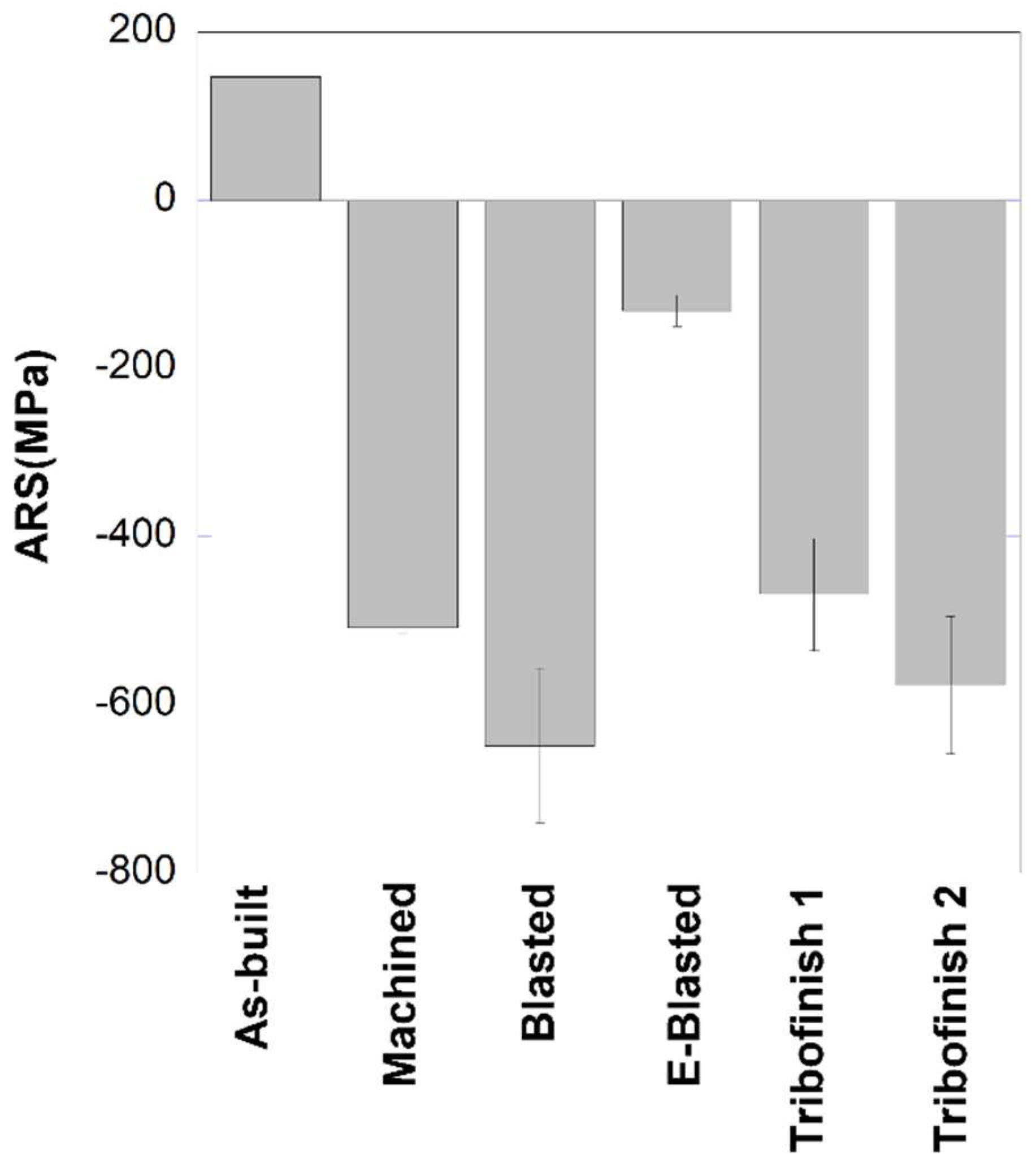
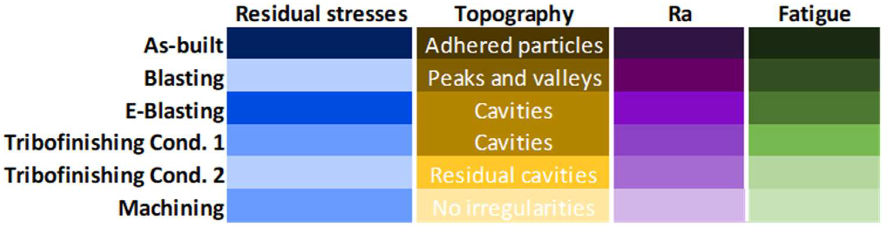
  • HIP has been found not to be totally effective in removing surface residual stresses. There are remaining tensile residual stresses which are converted to compressive after applying the surface treatments;
  • All the studied surface modification methods are effective in reducing roughness. Tribofinishing leads to the maximum roughness reduction, 97%, similar to machining finishing;
  • Although tribofinishing significantly reduced the roughness and achieved a value well below 1 µm, the fatigue response is not comparable to that obtained with machining due to the irregularities found on the surface. It would be required to optimize the tribofinishing process even further in order to obtain completely smooth surfaces;
  • It appears that for fatigue, roughness is the most critical surface property, more than the introduced compressive residual stresses. This is evident in blasted samples. High compressive residual stresses are introduced when blasting, but the high roughness promotes the premature failure of the samples;
  • The subsequent electropolishing applied to blasted samples (E-Blasting treatment) reduces the surface roughness and the level of introduced compressive residual stresses by the blasting process. Due to the compressive nature of the residual stresses and the low roughness achieved, fatigue is improved compared to the blasted samples;
  • Low roughness values and compressive residual stresses favor fatigue response;
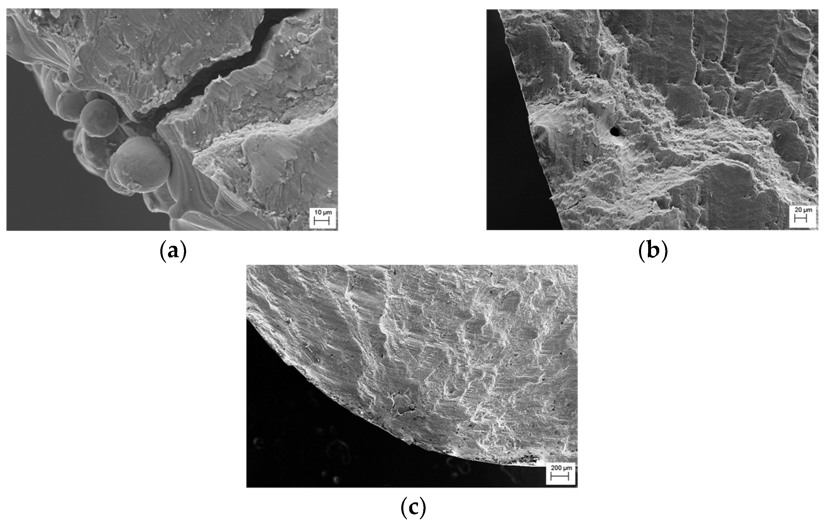
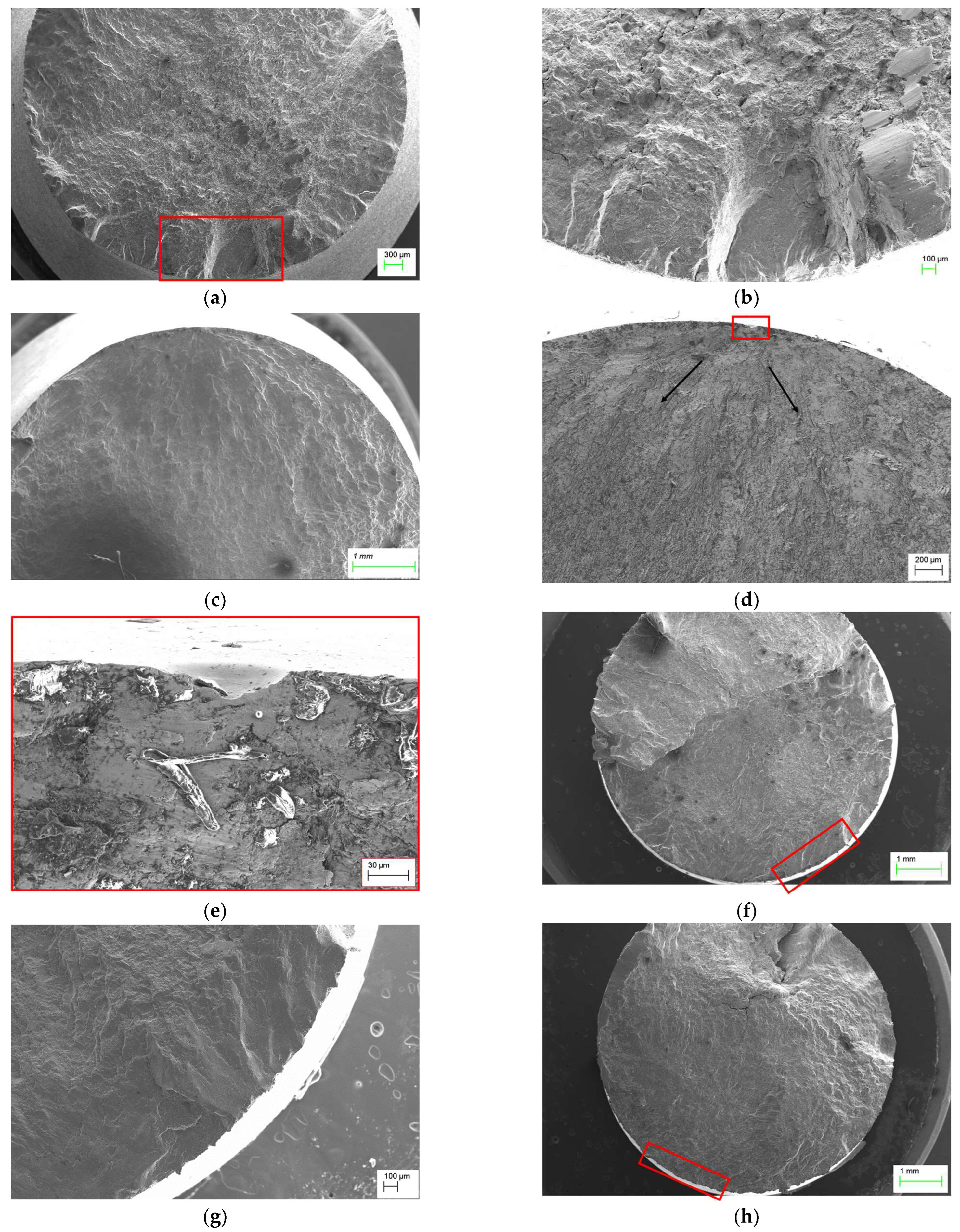
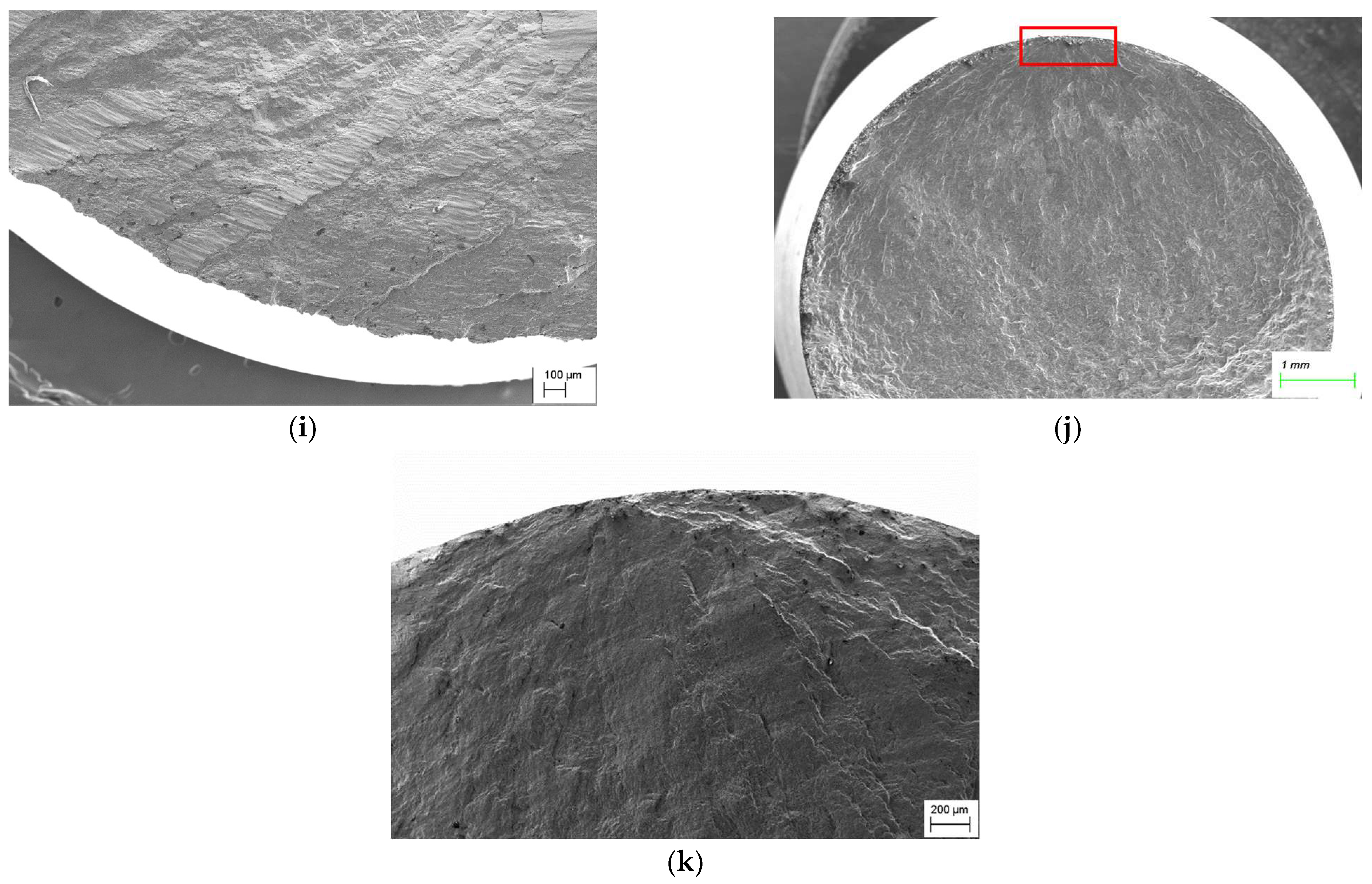
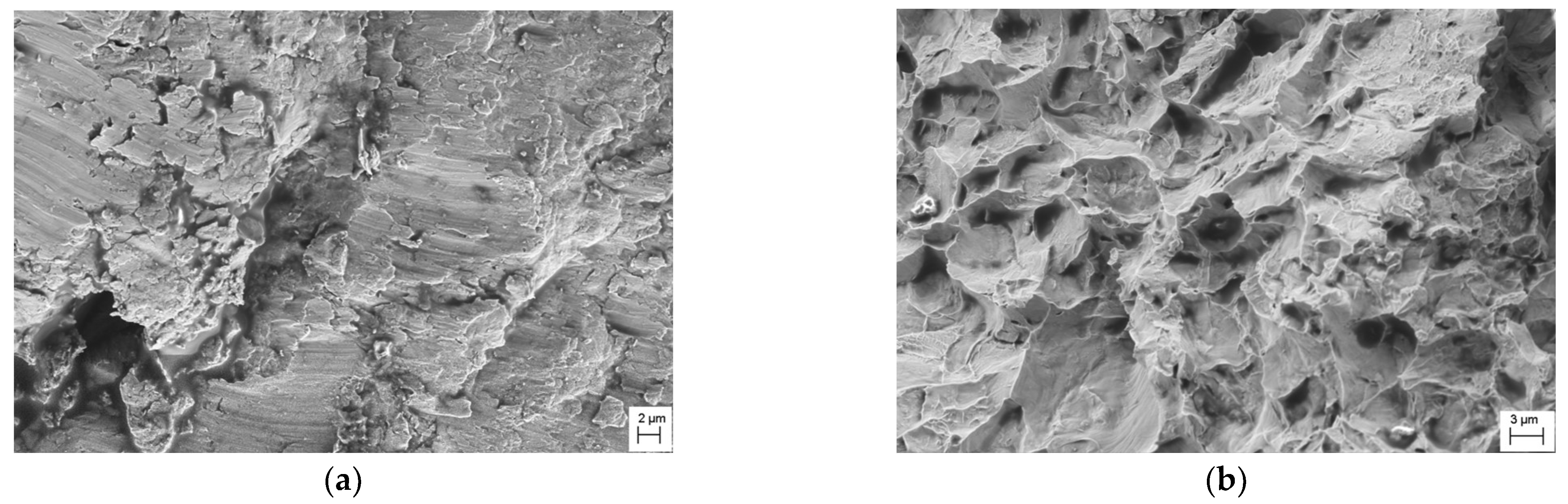
  • All the samples fracture from the surface; there are no internal critical defects due to the application of HIP treatment. The irregularities found in the form of cavities or pits are stress concentrators that initiate cracks;
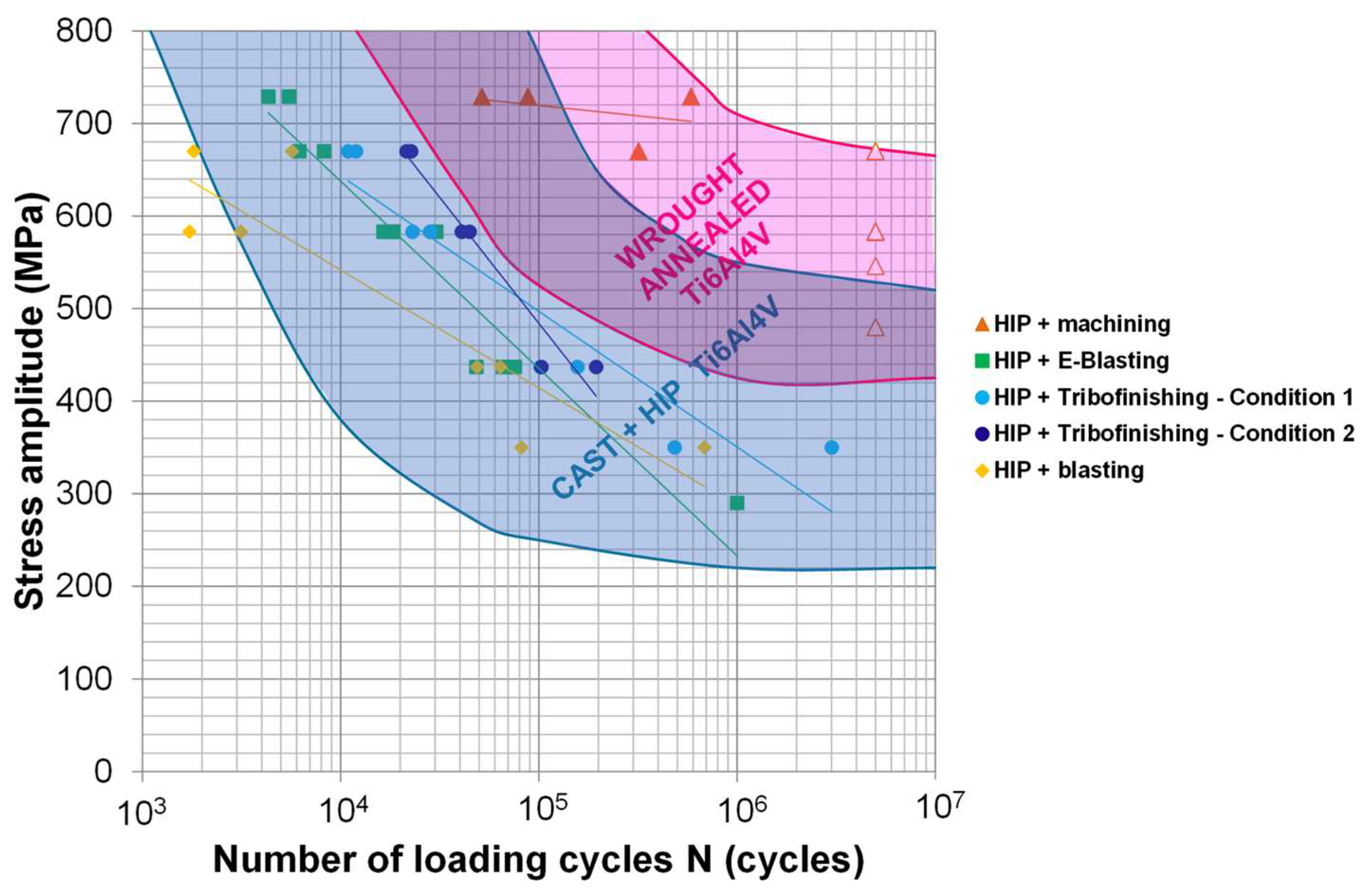
  • It has been demonstrated that the fatigue properties of the samples with the applied surface treatments are comparable to the casting material, except for the machined samples, which show the best fatigue properties, comparable to the conventional Ti6Al4V wrought material. Thus, machining could be substituted by these methods for applications with lower requirements;
  • It would be interesting to analyze the electropolishing method by itself, improving the surface roughness reduction, to verify its capability to even improve the results since it could be an option for additive complex parts where mechanical treatments such as machining or tribofinishing are not possible to use.

Author Contributions

Conceptualization, A.M.M., M.B.G.-B. and P.J.A.; methodology, M.B.G.-B., E.E., M.C. and F.G.; software, F.G.; validation, J.A.; investigation, I.Q., E.E., M.C., J.A. and F.G.; data curation, M.C.; writing—original draft preparation, A.M.M.; writing—review and editing, A.M.M., M.B.G.-B., I.Q., P.J.A. and M.C.; supervision, A.M.M., M.B.G.-B., I.Q. and P.J.A.; project administration, A.M.M.; funding acquisition, A.M.M., M.B.G.-B., I.Q. and P.J.A. All authors have read and agreed to the published version of the manuscript.

Funding

This research was funded by the Departamento de Desarrollo Económico, Sostenibilidad y Medio Ambiente of the Basque Government (ELKARTEK 2022 KK-2022/00070), by the Departamento de Desarrollo Económico y Competitividad of the Basque Government (ELKARTEK 2019 KK-2019/00077) and by the European Union (project TIFAN, JTI-CS-2013-1-ECO-01-066).

Data Availability Statement

The research data presented in this study are available on request from the corresponding author.

Conflicts of Interest

The authors declare no conflict of interest.

References

  1. Dutta, B.; Froes, F.H. Additive Manufacturing of Titanium Alloys. Adv. Mater Process. 2014, 172, 18–23. [Google Scholar]
  2. Edwards, P.; O’Conner, A.; Ramulu, M. Electron Beam Additive Manufacturing of Titanium Components: Properties and Performance. J. Manuf. Sci. Eng. 2013, 135, 061016. [Google Scholar] [CrossRef]
  3. Yu, H.; Li, F.; Wang, Z.; Zeng, X. Fatigue performances of selective laser melted Ti-6Al-4V alloy: Influence of surface finishing, hot isostatic pressing and heat treatments. Int. J. Fatigue 2019, 120, 175–183. [Google Scholar] [CrossRef]
  4. Kasperovich, G.; Hausmann, J. Improvement of fatigue resistance and ductility of TiAl6V4 processed by selective laser melting. J. Mater. Process. Tech. 2015, 220, 202–214. [Google Scholar] [CrossRef]
  5. Thöne, M.; Leuders, S.; Riemer, A.; Tröster, T.; Richard, H.A. Influence of heat-treatment on Selectice Laser Melting products—e.g. Ti6Al4V. In Proceedings of the Annual International Solid Freeform Fabrication Symposium, Austin, TX, USA, 6–8 August 2012; pp. 492–498. [Google Scholar]
  6. Leuders, S.; Thöne, M.; Riemer, A.; Niendorf, T.; Tröster, T.; Richard, H.A.; Maier, H. On the mechanical behaviour of titanium alloy TiAl6V4 manufactured by selective laser melting: Fatigue resistance and crack growth performance. Int. J. Fatigue 2013, 48, 300–307. [Google Scholar] [CrossRef]
  7. Mertova, K.; Dzugan, J.; Roudnicka, M. Fatigue properties of SLM-produced Ti6Al4V with various post-processing processes. IOP Conf. Ser. Mater Sci. Eng. 2019, 461, 012052. [Google Scholar] [CrossRef] [Green Version]
  8. Malefane, L.B.; du Preez, W.B.; Maringa, M. High Cycle Fatigue Properties of as-built Ti6Al4V (ELI) produced by Direct Metal Laser Sintering. South Afr. J. Ind. Eng. 2017, 28, 188–199. [Google Scholar] [CrossRef] [Green Version]
  9. Benedetti, M.; Cazzolli, M.; Fontanari, V.; Leoni, M. Fatigue limit of Ti6Al4V alloy produced by Selective Laser Sintering. Procedia Struct. Integr. 2016, 2, 3158–3167. [Google Scholar] [CrossRef] [Green Version]
  10. Gong, H.; Rafi, K.; Starr, T.; Stucker, B. Effect of defects on fatigue tests of as-built Ti-6Al-4V parts fabricated by Selective Laser Melting. In Proceedings of the 23rd Annual International Solid Freeform Fabrication Symposium, Austin, TX, USA, 6–8 August 2012; pp. 499–506. [Google Scholar]
  11. Chastand, V.; Tezenas, A.; Cadoret, Y.; Quaegebeur, P.; Maia, W.; Charkaluk, E. Fatigue characterization of Titanium Ti-6Al-4V samples produced by Additive Manufacturing. Procedia Struct. Integr. 2016, 2, 3168–3176. [Google Scholar] [CrossRef] [Green Version]
  12. Rekedal, K.D. Investigation of the High-Cycle Fatigue Life of Selective Laser Melted and Hot Isostatically Pressed Ti-6Al-4V. In Additive Manufacturing Handbook; CRC: Boca Raton, FL, USA, 2015; pp. 1–122. [Google Scholar]
  13. Tong, J.; Bowen, C.R.; Persson, J.; Plummer, A. Mechanical properties of titanium-based Ti-6Al-4V alloys manufactured by powder bed additive manufacture. Mater. Sci. Technol. 2016, 33, 138–148. [Google Scholar] [CrossRef] [Green Version]
  14. Jamshidi, P.; Aristizabal, M.; Kong, W.; Villapun, V.; Cox, S.C.; Grover, L.M.; Attallah, M.M. Selective Laser Melting of Ti-6Al-4V: The Impact of Post-processing on the Tensile, Fatigue and Biological Properties for Medical Implant Applications. Materials 2020, 13, 2813. [Google Scholar] [CrossRef]
  15. Fatemi, A.; Molaei, R.; Simsiriwong, J.; Sanaei, N.; Pegues, J.; Torries, B.; Attallah, M.M. Fatigue Behavior of Additive Manufactured Materials: An Overview of Some Recent Experimental Studies on Ti-6Al-4V Considering Various Processing and Loading Direction Effects. Fatigue Fract. Eng. Mater. Struct. 2019, 42, 991–1009. [Google Scholar] [CrossRef]
  16. Kahlin, M. Fatigue Performance of Additive Manufactured Ti6Al4V in Aerospace Applications; Linköping University: Linköping, Sweden, 2017. [Google Scholar]
  17. Stoffregen, H.A.; Butterweck, K.; Abele, E. Fatigue Analysis in Selective Laser Melting: Review and Investigation of Thin-Walled Actuator Housings. In Proceedings of the 25th Solid Freeform Fabrication Symposium, Austin, TX, USA, 12–14 August 2013; pp. 635–650. [Google Scholar]
  18. Fousova, M.; Vojtech, D.; Dzugan, J. Is surface finish really decisive for the fatigue of additively manufactured Ti alloy? In Proceedings of the 27th International Conference on Metallurgy and Materials, Brno, Czech Republic, 23–25 May 2018; pp. 1533–1538. [Google Scholar]
  19. Xu, W.; Sun, S.; Elambasseril, J.; Liu, Q.; Brandt, M.; Qian, M. Ti-6Al-4V Additively Manufactured by Selective Laser Melting with Superior Mechanical Properties. JOM 2015, 67, 668–673. [Google Scholar] [CrossRef]
  20. Cutolo, A.; Elangeswaran, C.; Formanoir CDe Muralidharan, G.K.; Van Hooreweder, B. Effect of Heat Treatments on Fatigue Properties of Ti-6Al-4V and 316L Produced by Laser Powder Bed Fusion in As-Built Surface Condition. In TMS 2019 148th Annual Meeting & Exhibition Supplemental Proceedings; The Minerals, Metals & Materials Series; Springer International Publishing: Cham, Switzerland, 2019; pp. 395–405. [Google Scholar] [CrossRef]
  21. Navarro, C.; Vázquez, J.; Domínguez, J.; Periñán, A.; García, M.H.; Lasagni, F.; Bernarding, S.; Slawik, S.; Mücklich, F.; Boby, F.; et al. Effect of surface treatment on the fatigue strength of additive manufactured Ti6Al4V alloy. Frat. Ed Integrità Strutt. 2020, 53, 337–344. [Google Scholar] [CrossRef]
  22. Soyama, H.; Okura, Y. The use of various peening methods to improve the fatigue strength of titanium alloy Ti6Al4V manufactured by electron beam melting. Mater. Sci. 2018, 5, 1000–1015. [Google Scholar] [CrossRef]
  23. Yan, X.; Yin, S.; Chen, C.; Jenkins, R.; Lupoi, R.; Bolot, R.; Ma, W.; Kuang, M.; Liao, H.; Lu, J.; et al. Fatigue strength improvement of selective laser melted Ti6Al4V using ultrasonic surface mechanical attrition. Mater. Res. Lett. 2019, 7, 327–333. [Google Scholar] [CrossRef]
  24. Walker, P.; Malz, S.; Trudel, E.; Nosir, S.; Elsayed, M.S.A.; Kok, L. Effects of Ultrasonic Impact Treatment on the Stress—Controlled Fatigue Performance of Additively Manufactured DMLS Ti-6Al-4V Alloy. Appl. Sci. 2019, 9, 4787. [Google Scholar] [CrossRef] [Green Version]
  25. Witkin, D.B.; Patel, D.N.; Helvajian, H.; Steffeney, L.; Diaz, A. Surface Treatment of Powder-Bed Fusion Additive Manufactured Metals for Improved Fatigue Life. J. Mater. Eng. Perform. 2019, 28, 681–692. [Google Scholar] [CrossRef]
  26. Bagherifard, S.; Beretta, N.; Monti, S.; Riccio, M.; Bandini, M.; Guagliano, M. On the fatigue strength enhancement of additive manufactured AlSi10Mg parts by mechanical and thermal post-processing. Mater. Des. 2018, 145, 28–41. [Google Scholar] [CrossRef]
  27. Uzan, N.E.; Ramati, S.; Shneck, R.; Frage, N.; Yeheskel, O. On the effect of shot-peening on fatigue resistance of AlSi10Mg specimens fabricated by additive manufacturing using selective laser melting (AM-SLM). Addit. Manuf. 2018, 21, 458–464. [Google Scholar] [CrossRef]
  28. Fitzpatrick, M.E.; Fry, A.T.; Holdway, P. NPL Good Practice Guide no. 52: Determination of Residual Stresses by X-Ray Diffraction; National Physical Laboratory: Teddington, UK, 2002. [Google Scholar]
  29. Vayssette, B.; Saintier, N.; Brugger, C.; Elmay, M.; Pessard, E. Surface roughness of Ti-6Al-4V parts obtained by SLM and EBM: Effet on the High Cycle Fatigue life. In Proceedings of the 7th International Conference on Fatigue Design, Senlis, France, 29–30 November 2018; pp. 89–97. [Google Scholar] [CrossRef]
  30. Wycisk, E.; Claus, E.; Siddique, S.; Walther, F. High Cycle Fatigue (HCF) Performance of Ti- 6Al-4V Alloy Processed by Selective Laser Melting. Adv. Mater. Res. 2013, 816–817, 134–139. [Google Scholar] [CrossRef]
  31. Kempen, K.; Thijs, L.; Van Humbeeck, J.; Kruth, J.-P. Mechanical Properties of AlSi10Mg Produced by Selective Laser Melting. Phys. Procedia 2012, 39, 439–446. [Google Scholar] [CrossRef] [Green Version]
  32. Qiu, C.; Adkins, N.J.E.; Attallah, M.M. Microstructure and tensile properties of selectively laser-melted and of HIPed laser-melted Ti–6Al–4V. Mater. Sci. Eng. A 2013, 578, 230–239. [Google Scholar] [CrossRef]
  33. Vrancken, B.; Thijs, L.; Kruth, J.-P.; Van Humbeeck, J. Heat treatment of Ti6Al4V produced by Selective Laser Melting: Microstructure and mechanical properties. J. Alloy. Compd. 2012, 541, 177–185. [Google Scholar] [CrossRef] [Green Version]
  34. Leinenbach, C.; Eifler, D. Fatigue and cyclic deformation behaviour of surface-modified titanium alloys in simulated physiological media. Biomaterials 2006, 27, 1200–1208. [Google Scholar] [CrossRef]
  35. Roudnicka, M.; Mertova, K.; Vojtech, D. Influence of hot isostatic pressing on mechanical response of as-built SLM titanium alloy. IOP Conf. Ser. Mater. Sci. Eng. 2019, 629, 012034. [Google Scholar] [CrossRef]
  36. Snyder, J.C.; Thole, K.A. Understanding Laser Powder Bed Fusion Surface Roughness. J. Manuf. Sci. Eng. 2020, 14, 071003. [Google Scholar] [CrossRef]
  37. Benedetti, M.; Torresani, E.; Leoni, M.; Fontanari, V.; Bandini, M.; Pederzolli, C.; Potrich, C. The effect of post-sintering treatments on the fatigue and biological behavior of Ti-6Al-4V ELI parts made by selective laser melting. J. Mech. Behav. Biomed. Mater. 2017, 71, 295–306. [Google Scholar] [CrossRef]
  38. Wycisk, E.; Siddique, S.; Herzog, D.; Walther, F.; Emmelmann, C. Fatigue Performance of laser Additive Manufactured Ti-6Al-4V in Very high cycle Fatigue regime up to 109 cycles. Front Mater. 2015, 2, 72. [Google Scholar] [CrossRef] [Green Version]
  39. Chan, K.S.; Koike, M.; Mason, R.L.; Okabe, T. Fatigue Life of Titanium Alloys Fabricated by Additive Layer Manufacturing Techniques for Dental Implants. Met. Mater. Trans. A 2013, 44, 1011–1022. [Google Scholar] [CrossRef]
Figure 1. SEM images of gas-atomized Ti6Al4V powder. (a) Low magnification showing spherical particles (b) Details of powder particles.
Jmmp 07 00119 g001
Figure 2. Abrasive chips considered in tribofinishing.
Jmmp 07 00119 g002
Figure 3. (a) Tensile samples’ geometry and (b) fatigue samples’ geometry. Unit: mm.
Jmmp 07 00119 g003
Figure 4. Residual porosity of (a) as-built samples and (b) HIPed samples.
Jmmp 07 00119 g004
Figure 5. FE-SEM micrographs of Ti6Al4V samples: (a,c) as-built state and (b,d) HIP condition.
Jmmp 07 00119 g005aJmmp 07 00119 g005b
Figure 6. Engineering stress–strain curves for the as-built condition and for samples with HIP treatment.
Jmmp 07 00119 g006
Figure 7. Surface roughness Ra of post-processed fatigue sample.
Jmmp 07 00119 g007
Figure 8. Confocal microscope 3D representation of (a) as-built, (b) machined, (c) blasted, (d) E-Blasted, (e) tribofinished in condition 1 and (f) tribofinished in condition 2 surfaces.
Jmmp 07 00119 g008aJmmp 07 00119 g008b
Figure 9. SEM images of surface topography in (a) as-built state, (b) machined, (c) blasted, (d) E-Blasted, (e) tribofinished in condition 1 and (f) tribofinished in condition 2.
Jmmp 07 00119 g009
Figure 10. Axial residual stresses measured in as-built and post-processed samples after HIP.
Jmmp 07 00119 g010
Figure 11. S-N curve of Ti6Al4V alloy processed by L-PBF with different surface conditions: blasting, E-Blasting, tribofinishing and machining.
Jmmp 07 00119 g011
Figure 12. Fracture surfaces of fatigue samples, (a) conventionally heat-treated and as-built surface state, (b) conventionally heat-treated and machined and (c) HIPed and machined.
Jmmp 07 00119 g012
Figure 13. Fracture surfaces of fatigue samples after (a,b) blasting, (c,d) E-Blasting, (e) E-Blasting focused on surface cavity, (f,g) tribofinishing (initial conditions), (h,i) tribofinishing (optimized conditions) and (j,k) machined. Red squares indicate crack initiation sites while black arrows crack growth direction.
Jmmp 07 00119 g013aJmmp 07 00119 g013b
Figure 14. Fracture surfaces of fatigue samples after E-Blasting. (a) Area close to the crack initiation site and (b) area far from the crack initiation site.
Jmmp 07 00119 g014
Figure 15. Color-based ranking of surface properties and fatigue behavior as a function of the applied surface treatment.
Jmmp 07 00119 g015
Figure 16. Fatigue performance of additively manufactured and surface-treated Ti6Al4V samples and comparison with conventional Ti6Al4V materials.
Jmmp 07 00119 g016
Table 1. Routes employed in tribofinishing.
RoutePhase 1Phase 2Phase 3Drying
MQT (h)MQT (h)MQT (h)T (h)
12151115.25120.256.5
22115112112432
Table 2. Tensile properties of samples in the as-built state (non-heat-treated) and after applying HIP treatment.
Sampleσy (MPa)UTS (MPa)ε (%)
As-built1105 ± 8.31259 ± 9.68.5 ± 0.2
HIP 920 °C942 ± 4.91019 ± 4.212.5 ± 0.3
Table 3. Initial fatigue test results.
SampleHeat TreatmentSurface ConditionStress Amplitude (MPa)Cycles to Failure
1850 °CAs-built55014,305
2850 °CMachined4803,186,766
3HIP 920 °CMachined546>5,000,000
Disclaimer/Publisher’s Note: The statements, opinions and data contained in all publications are solely those of the individual author(s) and contributor(s) and not of MDPI and/or the editor(s). MDPI and/or the editor(s) disclaim responsibility for any injury to people or property resulting from any ideas, methods, instructions or products referred to in the content.

