1. Introduction
The goal of machining technologies, such as turning, milling, drilling, boring [
1,
2], as well as broaching [
3], and ultrasonic machining, is to achieve precise dimensional accuracy and desired surface roughness [
4,
5]. However, the cutting process comes with various accompanying phenomena, including plastic deformation of the chip, chip formation, cutting forces, tool wear, residual stress, surface roughness [
6,
7,
8,
9], temperature [
10], and vibrations. In particular, machining vibrations can impair the processing quality and performance [
11], making it crucial to find ways to reduce them in engineering production. This issue is especially relevant for deep-hole processing using boring mandrels [
12] or deep turning [
13].
The use of long overhang tools is often necessary to reach deep and narrow cavities in workpieces, but it can lead to increased tool deflection and vibration, affecting the quality of the machined surface and reducing tool life. Therefore, understanding the dynamic behavior of the internal turning tool during machining is crucial to improve the process performance and reliability [
14].
Stiffness can be expressed in terms of static or dynamic stiffness. The static stiffness of a bar refers to its ability to resist a bending force under static conditions, such as a force perpendicular to the main axis of the turning bar. A structure that deflects less under a force is considered more rigid. On the other hand, dynamic stiffness refers to a bar’s ability to resist oscillating forces or vibrations. This property is crucial for a turning bar as it measures its capacity to dampen the vibrations that occur during machining, which heavily depends on its overhang [
15,
16].
In internal turning, the occurrence of chatter directly depends on the dynamic stability of the tool and its clamping system and not so much on the workpiece. Once the clamping system is sufficiently stiff, the main factor that influences the deflection of the tooltip is the ratio of the length of the holder’s unloading, (
L), to its diameter, (
D). The dynamic stiffness of the bar decreases as the length of the bar holder, (
L), increases and its diameter, (
D), decreases. This causes vibration, and the existence of vibrations contributes to the deterioration of the roughness of the machined surfaces; a decrease in the durability of the cutting edge and a decrease in the life of the cutting tool also occur [
15].
When the overhang increases under constant machining conditions, the vibration amplitude also increases. However, modifications to the bar, such as the implementation of a “damping effect,” can extend the machining capacity to longer overhangs. This “damping effect” reduces the amplitude of oscillatory movements over time, indicating a high degree of dynamic stiffness. The amount of deflection of the bar at the tool tip, which results from applied cutting forces, is directly related to the overhang. The magnitude of the bar deflection depends on various factors such as bar material, diameter, overhang, and the intensity of tangential and radial cutting forces. To determine the deflection (
θ) in the cantilevered boring bar, Equation (1) can be used, considering the tool as a cylinder. In this equation, (
F) represents the shear force perpendicular to the tool axis, (
E) represents the Young’s modulus of the tool material, and (
L3/D4) represents the tool’s slenderness coefficient (TSC) [
16,
17].
In recent years, significant efforts have been made to investigate the dynamic stability of internal turning tools, especially for long overhangs. Several studies have proposed analytical, numerical, and experimental approaches to model and predict the tool’s dynamic behavior under different cutting conditions and geometries. However, there is still a lack of consensus on the most suitable method to evaluate the tool’s dynamic stability and its relationship with machining vibration [
18].
Urbikain [
19] suggested that stability diagrams combined with a finite element analysis are effective in considering the dynamic performance of a machine tool for a specific machining operation and can contribute to reducing machining vibration. The author presents two models based on a multi-DOF analysis to obtain stability charts in heavy-duty turning processes, which can assess and select the most performing machine, toolholder, and cutting tool for a specific operation. The models can evaluate the changes in stability boundaries for a range of input parameters, such as modal data, cutting coefficients, and the tool cutting edge angle. Overall, the text suggests that the stability analysis can help in improving productivity and reducing machining vibration in machine tools.
In [
12], authors consider the issue of modeling the oscillations of a boring mandrel with a vibration damper connected to the mandrel with a viscoelastic coupling. A mathematical model of the boring mandrel oscillations, machine support, and inertial body (damper) are developed in the form of a differential equations system. The model is made in the form of a four-mass system of connected bodies. As the simulation result, it was found that the use of a vibration damper can significantly reduce the amplitude of the boring mandrel’s natural vibrations when pulsed, and also significantly reduce the amplitude of the forced vibrations when exposed to periodic disturbing forces.
We present several design approaches, including dynamic vibration absorbers (DVAs) [
20] and new composite materials for bars [
21,
22,
23], that can be used to mitigate machining vibrations. The Nyquist stability criterion [
24] was employed to predict the stability and instability of vibrations during steel machining. In addition, piezoelectric lateral damping was utilized in [
25], and a tuned mass damper (TMD) was implemented in [
26]. The authors of [
27,
28] employed a damping method using particles placed in the boring tool to eliminate chatter.
To enhance the effectiveness of boring operations, dynamic vibration absorbers (DVAs) can be employed to absorb vibration energy. In this context, the damping oil inside a hollow cylinder within the DVA constitutes the average damping, and parameters such as the cylinder’s length, inner and outer diameters, oil pressure, and excitation frequency are investigated to determine their effects on the damping value. The study finds that the stable cutting frequency range is restricted, as the cutting frequency needs to avoid not only the zone with a high vibration amplitude but also the unstable cutting region [
20].
In [
21], composite boring bars with an enhanced damping capacity were employed to mitigate vibration. A novel design of boring bars with different cross-sections was explored, and the static and dynamic behavior of these tools was investigated. A mathematical model was developed to determine the eigenfrequency and was compared against computer simulations and experimental data. To validate the proposed models, experimental machining tests were conducted to analyze the changes in vibroacoustic signals depending on the tool holder’s cross-sections. The results demonstrate that the composite material significantly improves the damping of boring bars, thereby reducing vibration compared to conventional boring bars.
The present study [
25] investigates the impact of piezoelectric shunt damping on chatter vibrations during a boring process. In the piezoelectric shunt damping technique, an electrical impedance is connected to a piezoelectric transducer that is bonded to the cutting tool. The circuit’s electrical impedance, comprising the piezoceramic transducer and the passive shunt, is adjusted to the cutting tool’s desired natural frequency to maximize damping. Both theoretical and experimental analyses demonstrate that implementing piezoelectric shunt damping leads to a considerable increase in the absolute stability limit for boring operations.
Particle damping is one of the promising damping techniques for effectively suppressing chatter in boring processes. This paper [
27] attempts at a hybrid approach in particle damping to increase the effectiveness of chatter suppression and enhance the machining stability. In this hybrid approach, Copper and Zinc particles are used together in equal proportion for packing inside the boring bar. The study finds that this combined packing significantly improves the damping characteristic compared to the un-modified boring bar and also the bar packed with a single (Cu or Zn) particle type. The assessment benchmarks were the dynamic characteristics, modal analysis, damping ratio, logarithmic decrement, and resonance gap of the machining system, as well as the displacement amplitude of the boring bar and the surface roughness of the workpiece. The displacement amplitude of the boring bar and the surface roughness of the workpiece in the combined packing case is reduced by 55% and 80%, respectively, when it is compared to the unmodified case.
This article [
28] presents a chatter suppression approach utilizing a particle-damping technique. The study reveals that particle damping significantly enhances surface finish and reduces tool wear in boring operations. The surface roughness (Ra) values obtained while machining with the particle-damped boring bar were compared with those achieved when machining with a solid boring bar. The results indicate that the effect of particle damping on roughness decreases as the feed rate increases.
Thomas et al. [
29] showed through experimental tests that the use of impact damper bars enables turning workpieces with deep holes, without impairing the surface roughness and tool life. The authors also verified that the tool life of both bars (without and with an absorber) is not different when the tool overhangs are at the stability regime. However, this limit is much higher for the impact damper bar than for the standard bar, indicating that the impact bar can be used in longer holes without damaging the tool’s life.
Generally, systems with impact absorbers use the kinetic energy of the vibrating structure to promote impacts. However, the use of an extra source of energy to promote more impact has also been studied recently. Aguiar et al. [
30] used compressed air flows to impose a greater amount of small ball collisions inside the cavity of a boring bar during the internal turning operation of hardened steels. In this case, the authors used small spheres partially filling the cavity of the tool holder, indicating that compressed air flows can favor impacts, increasing the efficiency of the absorber.
Our paper presents the technology of turning hardened workpieces and uses the particle vibration suppression method in the turning holder’s body.
Thomas et al. [
31] verified the stability of the internal turning operation over CBN tool life in long overhangs. In brief, when the boring bar is within its stable regime, the vibration amplitude of the tool is higher at the beginning of the insert lifespan than at the end, while the roughness values of the workpiece remained similar. However, in an unstable regime in boring bar operation in hardened materials with continuous cutting, the flank wear of the tool insert is mainly caused by the abrasion of CBN (Cubic nitride bor) particles originating from it. Substantial information was collected, and the collected information helps in the selection and proper configuration of the tool to determine the highest possible overhang of the internal turning bar without permitting the growth of vibration amplitudes to such a point as to cause instability in the machining system, damage to the productivity of the machines, and the low performance of the selected tools.
Self-excited vibrations occur in the turning process in radial directions, leading to nonuniform chip thickness distribution in areas within the vicinity of the cutting edge. In the case of cutting operations in the presence of vibrations, which is an unstable process, vibration amplitudes can increase exponentially until they reach the size of the chip’s thickness. These unstable vibrations generate large cutting forces that can damage the machine and cause premature tool wear, poor surface quality, and large dimensional defects [
32]. The author in [
15] discussed two frequencies: the natural frequency of the tool and the frequency of the rotation of the part. If the phenomenon of resonance of these frequencies occurs, then it can be damaged by the resonance phenomenon.
On the other hand, the amplitude of the regenerative vibration due to the geometric and micro-geometric errors of the workpiece influences productivity and the quality of machining, tool wear, or breakage, thus limiting the material’s removal rate [
33].
Thus, in order to minimize vibrations and achieve the lowest possible roughness during internal turning operations of hardened materials, it is important to consider several factors. These include tool selection (a carbide or ceramic tool with sharp cutting edges is preferred), cutting parameters (lower cutting speed, feed rate, and depth of cut are recommended, as well as a smaller tool overhang), workpiece fixturing (to prevent any movement or chatter during machining, the workpiece should be securely clamped), and machine rigidity (a machine with high rigidity and stability is recommended for machining hardened materials) [
34].
In addition to the already-mentioned factors, the vibration amplitude generated by the cutting process influences the roughness values, especially when these are very high, characterizing an unstable cut, which results in the complete instability of the tool [
35].
Several strategies have been developed to increase dynamic stiffness and reduce machining vibrations. This paper aims to contribute to the understanding of how the dynamic stability of internal turning tools for long overhangs can influence machining vibration. To achieve this goal, four different boring bar configurations will be discussed, including the standard boring bar, a carbide boring bar with a higher Young’s modulus than the standard one, and two anti-vibration tools with different passive damper mechanisms: the Silent tool, that acts as a tuned mass damper (TMD) system and the Impact Damper (ID) boring bar that modifies the linear momentum of the balls during multiple inelastic collisions inside the tool’s cavity [
36]. An experimental investigation is conducted to measure the dynamic stability of these tool configurations under identical test conditions, including cutting parameters, clamping system, workpiece material, insert, measurement procedure, and data collection. The effects of these configurations on machining vibration are analyzed in terms of the roughness and acceleration amplitude of the tool. The results provide valuable insights into the relationship between the tool’s dynamic stability and surface quality and can guide the selection of optimal tool overhang for internal turning of deep and narrow cavities.
In the case of pure turning technology, the following research works from recent years can be mentioned:
The cutting conditions such as depth of cut, feed rate, and cutting speed are the primary factors that affect vibration during turning. For example, it was shown by Malekian [
37] that increasing the depth of the cut can result in higher vibration levels while increasing the cutting speed can reduce vibration levels.
The tool’s geometry is another significant factor that affects vibration during turning. Researchers such as Ding [
38] have shown that changing the rake angle or nose radius of the cutting tool can influence the dynamics of the cutting process, which can lead to changes in vibration behavior.
The material properties of the workpiece also influence vibration during turning. Studies by Sun [
39] and Shen [
40] showed that materials with low damping properties, such as titanium alloys or hardened steels, can result in higher vibration levels due to the increased stiffness of the workpiece.
One such study by Yoon [
41] investigated the effect of cutting parameters on process damping in turning. The authors found that increasing the cutting speed and feed rate can increase process damping while increasing the depth of the cut reduced it. They also suggested that the optimal cutting parameters for achieving maximum process damping may differ depending on the workpiece material.
Another study by Shao [
42] focused on the effect of cutting tool geometry on process damping. The authors found that changing the tool’s geometry can affect the process damping behavior and suggested that using a tool with a larger edge radius can improve process damping.
Furthermore, a study by Zhang [
43] investigated the effects of process damping on chatter stability in turning. They found that process damping can significantly improve chatter stability, especially at higher spindle speeds and lower feed rates. The authors suggested optimizing process damping to improve chatter stability and machining efficiency.
Overall, the following recent works demonstrate the ongoing efforts to develop new methods and techniques for chatter suppression in turning processes, using approaches such as active control, model-based prediction and control, optimization, and piezoelectric actuators:
Kulkarni’s [
44] paper proposes a new approach to chatter control using magnetorheological dampers. The authors develop a mathematical model of the turning process and design a control algorithm that adjusts the damping force of the dampers in real-time to suppress chatter.
The paper [
45] presents a model-based approach to chatter prediction and control using artificial neural networks (ANNs). The authors develop a model of the turning process that includes the effects of the tool geometry, cutting parameters, and workpiece material. They then use the model to train an ANN to predict the onset of chatter and develop a control algorithm to suppress it.
Authors in [
46] propose a hybrid approach to chatter-free turning by combining particle swarm optimization (PSO) with ANNs. The authors develop a model of the turning process that includes the effects of cutting parameters such as cutting speed, feed rate, and depth of cut. They then use PSO to optimize the cutting parameters and train an ANN to predict the optimal parameters for chatter-free turning.
The paper [
47] by Ahmadi proposes a new approach to chatter suppression using piezoelectric actuators. The authors develop a mathematical model of the turning process and design a control algorithm that adjusts the position of the cutting tool in real-time to suppress chatter. They demonstrate the effectiveness of the approach through simulation and experimental results.
Several methods have been proposed to control vibration during turning. One approach is to use active damping systems, such as piezoelectric actuators or hydraulic dampers, to reduce the amplitude of the vibrations. For instance, Yang [
48] used a piezoelectric actuator to reduce vibration levels during the turning of an in-walled component. Another approach is to use passive damping systems, such as tuned mass dampers or dynamic absorbers, to absorb the energy of the vibrations. They designed a dynamic absorber to reduce the vibration levels during the turning of an aluminum alloy workpiece.
Process damping is an important phenomenon in the turning process that can significantly affect the stability and quality of the machining process. In recent years, numerous scientific publications have focused on investigating the process damping mechanism and exploring its effects on the turning process.
One such study by Yoon [
49] investigated the effect of cutting parameters on process damping in turning. The authors found that increasing the cutting speed and feed rate can increase process damping while increasing the depth of the cut can reduce it. They also suggested that the optimal cutting parameters for achieving maximum process damping may differ depending on the workpiece material.
Another study by Shao [
50] focused on the effect of cutting tool geometry on process damping. The authors found that changing the tool’s geometry can affect the process damping behavior and suggested that using a tool with a larger edge radius can improve process damping.
In a study by Seo and Lee [
51], the authors analyzed the effect of tool-holder damping on process damping. They found that increasing the tool-holder damping can improve process damping, leading to better surface finish and reduced tool wear. The authors also demonstrated that the effect of tool-holder damping is dependent on the cutting conditions, such as the depth of the cut and cutting speed.
Furthermore, a study by Zhang [
52] investigated the effects of process damping on chatter stability in turning. They found that process damping can significantly improve chatter stability, especially at higher spindle speeds and lower feed rates. The authors suggested optimizing process damping to improve chatter stability and machining efficiency.
Overall, these scientific publications demonstrate the importance of process damping in the turning process and highlight the various factors that can affect it. By understanding and optimizing these factors, it may be possible to improve machining efficiency, surface quality, and chatter stability in turning.
2. Materials and Methods
Table 1 describes the main data of the tools used in this work: the data were kindly supplied by Ltd. Sandvik Coromant (Sandviken, Sweden).
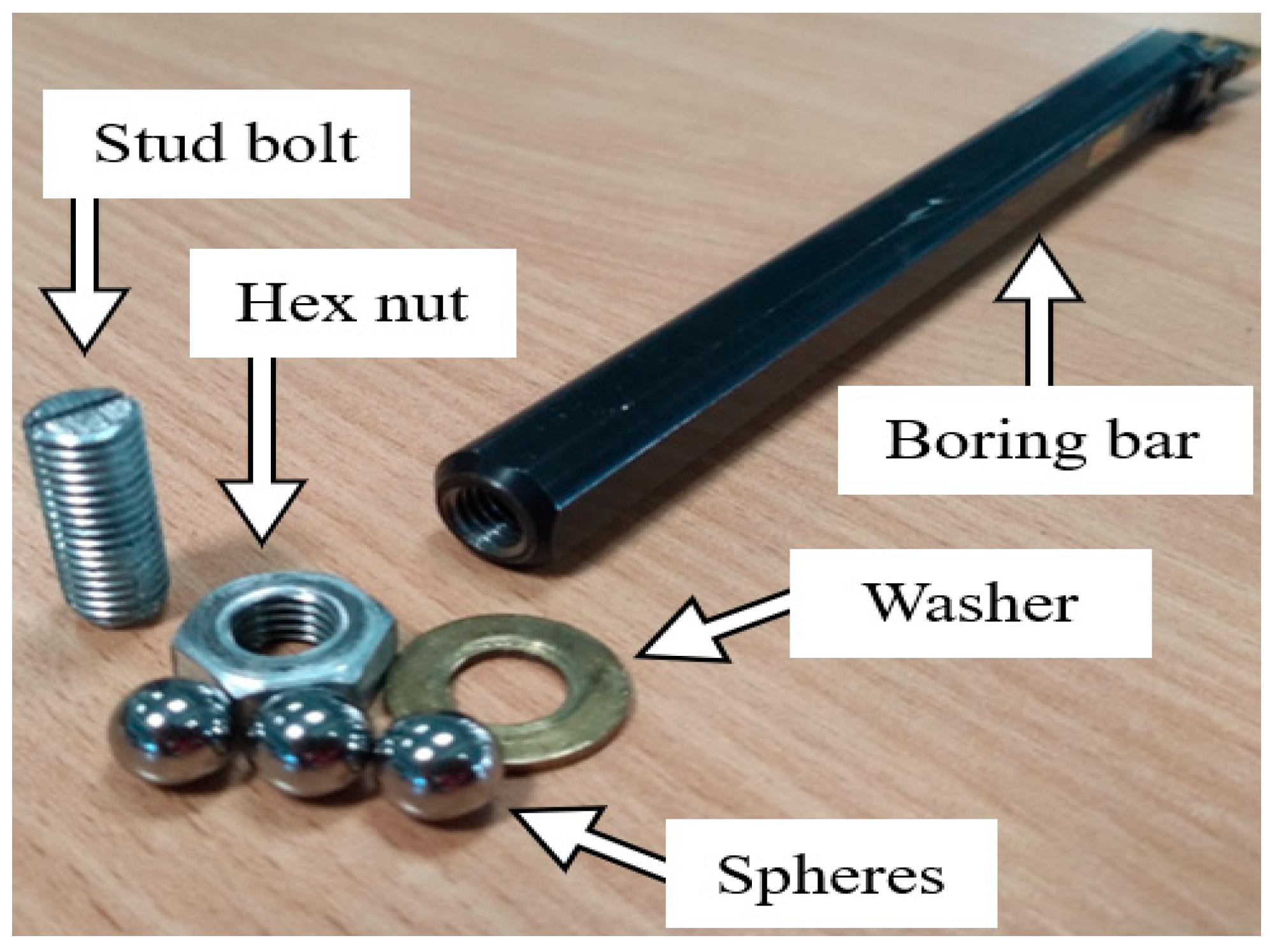
Table 1 shows that all of the tool holders have common parameters, which can also be verified by checking their codes. These parameters include a tool cutting edge angle of
κr = 95°, zero degrees orthogonal rake angle, −8.397° inclination angle, and −5° tool lead angle. In a specific case, the ID boring bar (custom design by Thomas W.) was manufactured with a cavity of dimensions Ø 8.43 mm × 180 mm and filled with steel balls of Ø 8 mm. The Ø 8.43 mm hole was drilled with a long carbide drill bit into the Ø 6.00 mm hole, which was originally used for internal cooling, as illustrated in
Figure 1.
The workpiece is DIN EN 1.2842 (ISO 90MnCrV8), and is made of steel. The shape of the workpiece was a cylinder. The material presents reasonable machinability. Its hardness after quenching changed from 54 to 59 HRC. During turning operations, we did not use cooling fluids, and the cutting parameters are as follows: depth of cut ap = 0.1 mm, feed f = 0.14 mm, and cutting speed vc = 360 mmin−1.
The roughness measurement was carried out according to a measurement schedule: number of measurements in one location—5 times; number of measurement points—3; displacement of measurement points on the component—equidistant points (120°). The laboratory’s temperature was 20 °C. The equipment used was a profilometer SURFCOM 1900SD2. Its resolution was equal to 0.04 µm in all measurement axes [
53]. The treatment of the roughness profile was according to the ISO 4288:1996 parameters [
54]. The parameters of roughness were measured: the arithmetic means deviation of the profile (
Ra) and the total height of the profile (
Rz).
In addition to the roughness measurements, we performed circularity measurements. These measurements were carried out on the CenterMAX coordinate measuring machine with a VAST XTR head from the company Zeiss. The measurement velocity was 15 mm/s in 5000 points. The accuracy of the measurement is provided as follows: 1.5 + L/250 at 26 °C.
From the measurements of vibration, we used the IRF (impulse response function) and FRF (frequency response function) of the tool holders. These functions were obtained for different overhangs and were used in hammer impact tests. The boring bars were clamped to the turret of the turning machine tool. An accelerometer was installed on the boring bar. Hammer blows were carried out on the boring bars. The measurement was made according to a measurement schedule: the number of blows was 5 for each ratio TSC, and there were 4 types of boring bars. The software enabled using a frequency range from 0 to 10,000 Hz and a minimum resolution of 1 Hz. Boring bar overhangs corresponding to a TSC greater than 1.68 were experimentally evaluated, as smaller ratios do not yield interesting results for this research study, as it has also been evaluated by [
55,
56].
Salgado [
57] and de Aguiar et al. [
17] used a dynamic ratio in the form (L
3/D
4), called the TSC in this paper and given in mm
−1, which means the tool’s slenderness coefficient. The conditions employed in the experiments are a contact tool diameter (D) for all tools D = 16 mm and different TSCs = 1.68, 4, 7.81, 13.50, 21.43, 32, and 45.56 mm
−1.
Next, we define specific terms that are important for deciding the evaluation of the experiments:
Stable cut: The vibrations present acceleration signals that are inferior to 100 m/s2; at the same time, the roughness of the machined surface was less than 0.8 µm.
Unstable cut: The vibrations present acceleration signals of more than 100 m/s2; at the same time, the roughness of the machined surface was more than 0.8 µm.
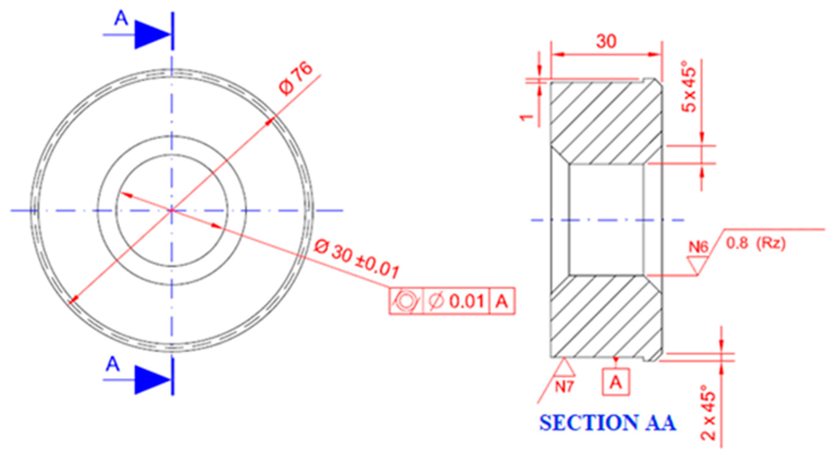
Figure 2 shows the dimensions of the specimen.
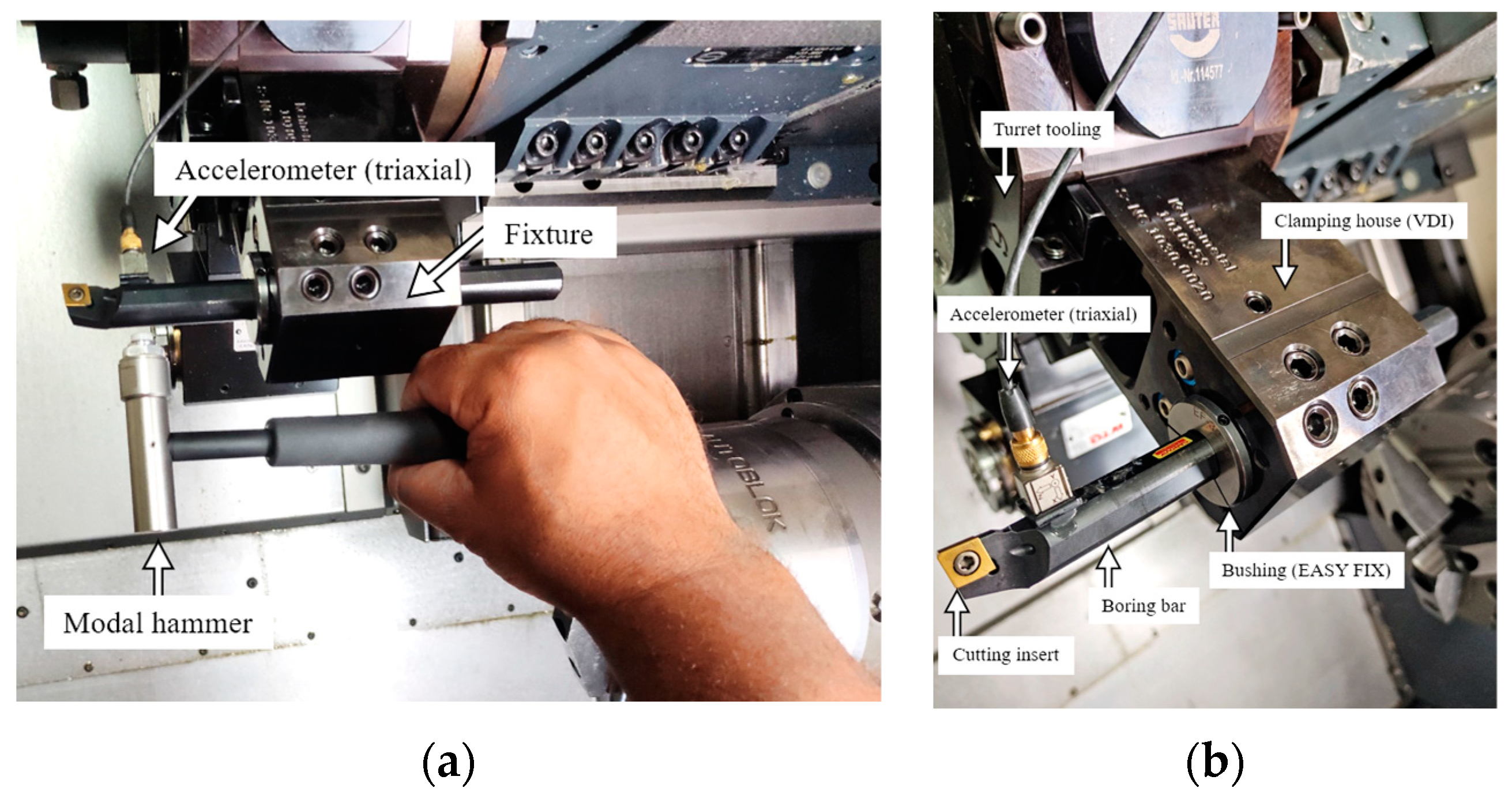
Figure 3 represents the setup and the layout of the main measurement equipment and lathe parts used during the experiments.
The experiments were performed in a DMG CTX alpha 500 CNC turning center with 40 CV of power and a maximum of 5000 rpm in the main spindle. In the clamping system assembled on the turret, a bushing with a length of 105 mm was used to clamp the boring bars with a diameter (
D) of 16 mm, specific density (
ρ) of 7860 kg/m
3, area of the cross-section (
A) of 1.64 × 10
−4 m
2 and inertia of the cross-section (
I) of 2.84 × 10
−9 m
4, a Poisson ratio of 0.33 and Young’s modulus of the tool (
Et) equal to 2.0 × 10
11 N/m
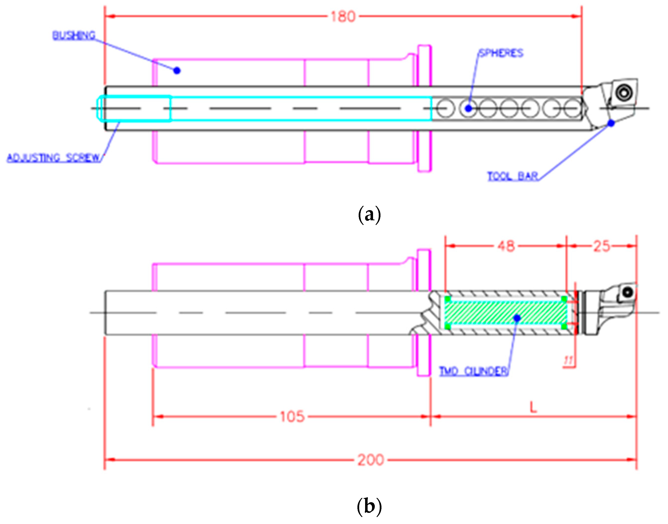
2 were used. One anti-vibrating tool (Silent tool), code 570-SCLCL-16-06, was used for the support, and code 570-3C 16 156 was used for the anti-vibrational bar and passive damping system shown in
Figure 4a where L is the tool overhangs and the parametric values are
kTMD = 703,744.74 N/m and
cTMD = 61.7 Ns/m. The rubber of the TMD system is 0.05 <
ζTMD < 0.12, and we used
ζTMD = 0.08. Similarly,
Figure 4b shows a replica of the ID designed in the paper [
14]. A boring bar, code A16R SCLCR 09-R, was used, and a cavity (diameter 8.32 mm × 180 mm) manufactured internally was filled with steel spheres, which have a diameter of 8 mm, a mass of 0.0021071 kg, and a Poisson ratio of 0.33, and Young’s modulus of the ball (
Eb) equals 2.0 × 10
11 N/m
2, resulting in a gap (
G) between the ball’s surface and cavity wall of 0.32 mm.
At the tip of the ID (impact damper) tool, CBN inserts—code CCGW09T308S01020F 7015 (class ISO H10)—and the Silent tool—TMD (tuned mass damper) with code CCGW 060208S01030F 7015. Both inserts have similar characteristics: with 50% CBN and ceramic phase of Al
2O
3 + TiCN (Sandvik CC 650), insert grain size 0.3–2.0 µm with rectangular geometry with hole for clamping, nose radius
rε = 0.8 mm, chamfer 0.1 mm,
x = 20°, entering angle
χr = 95°, rake angle
γ = +6°, rake angle
λ = −6°, nose angle
͛ = 80°, and clearance angle
α = 7° [
58]. It has lower toughness than inserts with a higher CBN content, but is still sufficient to maintain cutting-edge integrity. The advantage of this CBN class over the class with the highest CBN content is its greater chemical stability with iron. They were used to turn a hardened DIN EN 1.2842 (ISO 90MnCrV8) steel material workpiece with 55 HRC, and it comprises a ring workpiece geometry with the following properties: internal diameter of 30 mm, external length of 76 mm, length of 30 mm, 5 mm chamfers at the edges with a general dimensional, and roundness tolerance of +/− 0.01 mm and roughness limited to class N6.
Each tool was selected in order to check the overhang limit starting at TSC = 1.68 mm−1 and incrementing at 0.25 until the clamping limit of the ID and Silent tool (TSC = 1.68 mm−1) was vc = 300 m/min, f = 0.1 mm, and ap = 0.1 mm without using a coolant. The acceleration of the boring bars was measured at 20 mm before the tip of the tool during the cutting process with a triaxial piezoelectric accelerometer positioned in the x direction of the tool where the roughness is more affected. The measured vibration time was 4 s, and the sampling rate was 12,800 Hz. The signal of the accelerometer was filtered below 4500 Hz, while a Mitutoyo portable roughness meter, SURFCOM 1900SD2, was used to measure the roughness in the workpiece’s internal surface; an average of 3 measurements were taken with a cutoff of 0.8 mm and a total length of measurement of 4 mm relative to parameters (Ra) and (Rz).
3. Results
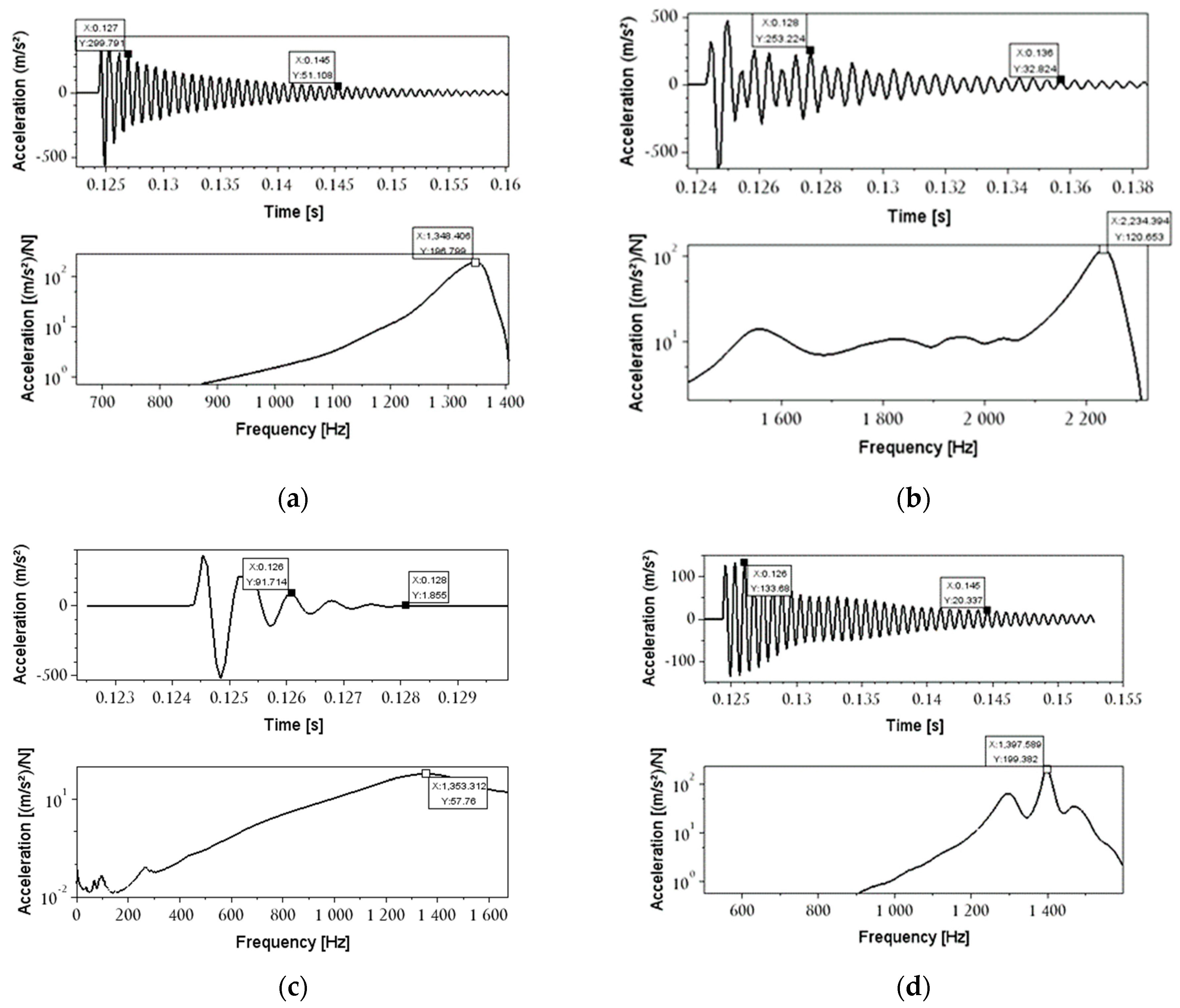
This section evaluates different boring bars in free and forced vibration conditions. During the initial phase of the experiments, the free vibrations were examined to ascertain the dynamic characteristics of the tools. This was accomplished through an impact test, which yielded information on the damping ratio, natural frequency, and dynamic and static stiffness of the tools without the application of any excitation force. The damping ratio of the tool was determined using the logarithmic decrement method in conjunction with the IRF signal, while the natural frequency and stiffness of the boring bar were determined using the FRF signal and given equations. Secondly, we carried out the forced vibration investigation to test the stability limit of the tools in different overhangs over the same cutting parameters, consequently the same cutting forces (excitation force). It is necessary to understand how the dynamic properties of the tool, in
Figure 5, were obtained.
The numbers of the experiment in
Figure 5 and the Equations (2) and (3) were considered. In that way, we collected a fragment of the IRF with the highest positive peak and after some time, the lowest positive peak of this fragment. We use those values in Equations (2) and (3) to estimate the damping ratio.
One of the dynamic properties is the damping ratio, which can be calculated from logarithmic decrement formulations. These describe a vibratory motion with a diminishing amplitude and time interval
, which separates two successive points
and
, where
. Then, the logarithmic attenuation ratio
,
[
59,
60] is calculated, which represents the rate at which the amplitude of motion decays:
where
is the damped period, which is measurable, and
(n) is the number of intervals for more precisely determining the damping coefficient. The dependence of the logarithmic decrement (
) of the system and the damping ratio (
) is expressed as follows [
61]:
In this paper, the highest resonant peak at the first bending mode is identified from the spectrum of frequencies, while the other peaks are negligible. Then, it is necessary to consider the acceleration amplitude (
ha) and natural frequency (
ω) at a certain overhang. Afterward, to obtain the compliance FRF amplitude (
hc), Equation (4) [
62,
63] was applied in order to understand the interaction between the reacceptance amplitude at the main resonant peak and the tool’s overhang:
where
kd is the dynamic stiffness of the tool in the corresponding overhang in Equation (4). According to [
64], the experimental static stiffness,
ks, can also be calculated as follows:
Applying Equations (2) and (3) for the data provided in
Figure 5a, the logarithmic decrement is provided as:
and the damping ratio for the boring bar is:
Applying Formulas (4) and (5) for the data provided in
Figure 5a, the dynamic stiffness is:
and the static stiffness for the boring bar is:
Table 2 summarizes the Lehr damping, static stiffness, and the natural frequencies parameters for TSC = 7.81 mm
−1.
After the detailed analyses in
Figure 5 and the results of
Table 2, we can observe that the ID has the highest damping ratio and practically the lowest static stiffness among the tools. This is due to the extra masses coupled to the tool, which comprise the impact passive damper system. In addition, the natural frequency of the ID is similar to the standard bar and TMD bars that have the same material properties. Contrary to that, the carbide tool has almost double the natural frequency of the other tools, and this is because the tool’s material has a Young’s modulus that is three times higher than the other tools. For that reason, carbide has the highest static stiffness and a relatively high damping ratio compared to the standard bar and ID boring bars. It is important to mention that there are no significant differences in the dynamic properties of the ID and standard tool in free vibration.
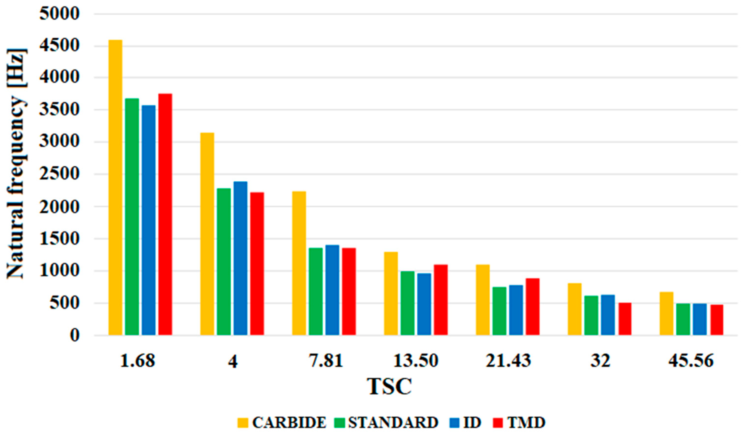
In order to analyze the influence of the overhang on the dynamic properties of the tools,
Figure 6 plots the main resonant peak of the vibration signal for the four tools. In order to analyze the influence of the overhang on the dynamic properties of the tools,
Figure 6 plots the main resonant peak of the vibration signal for the four tools. We used the term resonant peak as a synonym for the natural frequency of the FRF spectrum.
Figure 6 represents the highest peak of the FRF. It means the first natural frequency of the boring bar collected by the impact test.
The fluctuation in chip thickness caused by tool deflection (which also generates dimensional errors) is one of the causes of chatter due to the low Young’s modulus of the tool material [
65]. As observed in
Table 2 and
Figure 5, the natural frequency of carbide surpasses the other tools, which exhibit similar values with respect to natural frequencies. In addition, carbide has higher stiffness and less deflection compared to the other tools, which permits the tool to support higher excitation frequencies; in other words, it avoids chatter, which may affect other tools made of steel and not affect carbide tools that have higher natural frequencies. However, the discrepancy between the tools’ values is smaller in longer overhangs compared to shorter overhangs.
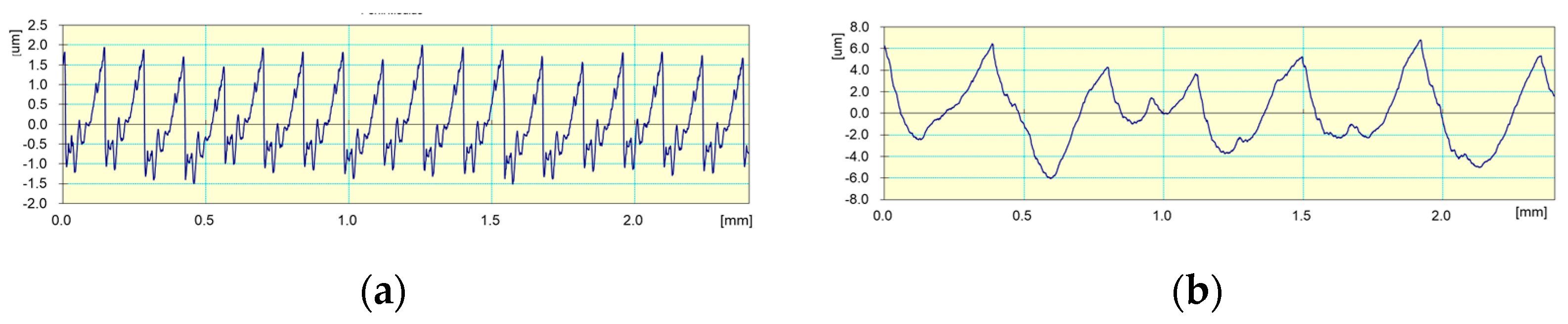
The profile of roughness is shown in
Figure 7 when carrying out cutting operations with a carbide boring bar in stable conditions at TSC = 4 mm
−1 (see
Figure 7a) and in unstable conditions at TSC = 21.43 mm
−1 (see
Figure 7b).
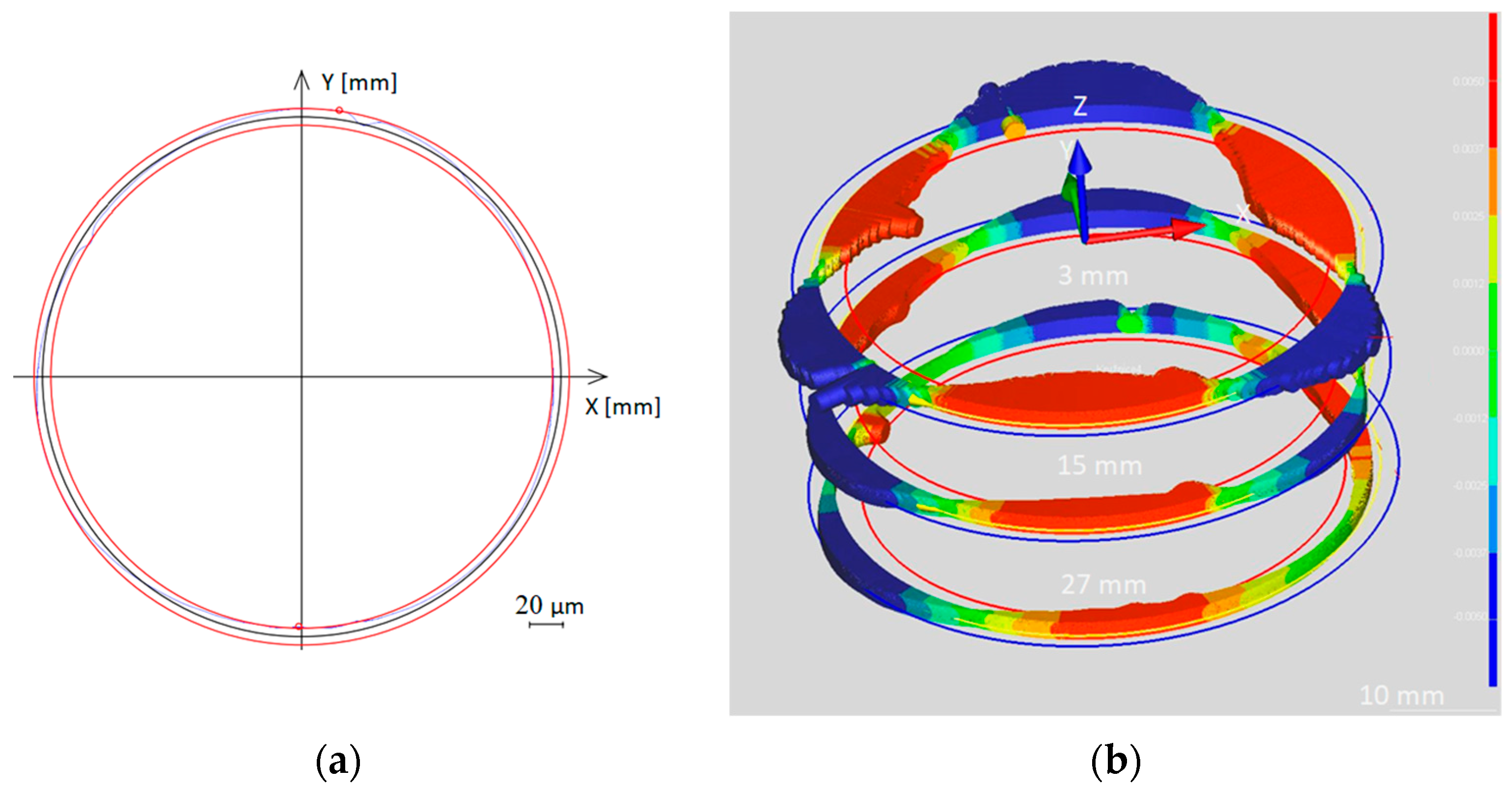
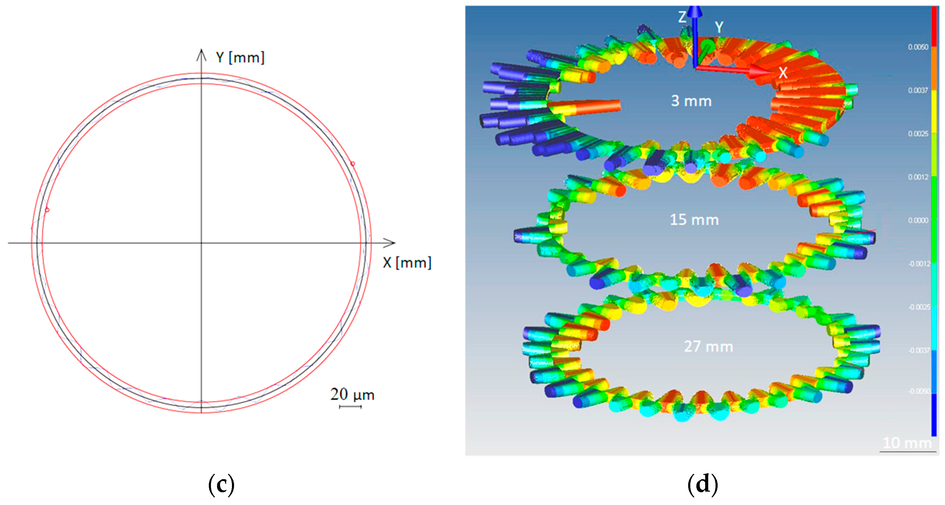
The circularity profile of the workpiece is shown in
Figure 8 when carrying out cutting operations with a carbide boring bar in stable conditions at TSC = 4 mm
−1 in 2D (
Figure 8a) and in 3D (see
Figure 8b), and in unstable conditions at TSC = 21.43 mm
−1 in 2D (see
Figure 8c) and in 3D (
Figure 8d).
To evaluate each experiment, the following postulates were constructed:
- (1)
The turning process was stable: No vibration marks were visible on the workpiece’s surface, and at the same time, the value of the mean arithmetic deviation (Ra) was less than 0.8 μm (see
Figure 9a).
- (2)
The turning process was unstable: There were visible signs of chatter on the surface of the workpiece, and at the same time, the value of the arithmetic mean deviation (Ra) was greater than 0.8 μm. Tool marks on the surface of the workpiece (internal hole) during an unstable turning process can be observed in
Figure 9b.
We observed that when the value of the mean arithmetic deviation (Ra) was greater than 0.8 μm, the chatter marks of
Figure 9b started to appear in the workpiece. The chatter marks are a collection of analyzed factors, where the highlighted main points are the long overhangs that cause a decrease in dynamic stiffness. Therefore, there is an increase in the tool’s deflection as a result of higher displacement amplitudes at the tip of the tool, and similarly, there are higher amplitudes in the roughness and circularity profile.
Table 3 summarizes the results of surface roughness measurements when machining different types of holders at different TSC limits.
It can be observed in
Table 3 that there are limits to the tool’s working range in stable and unstable modes. It is clear that all tools can retain similar roughness and acceleration amplitudes until their overhang is limited in the stable regime; on the other hand, in the unstable regime, roughness and the acceleration amplitude are high and produce substantial fluctuations among the values; this is typical chatter behavior.
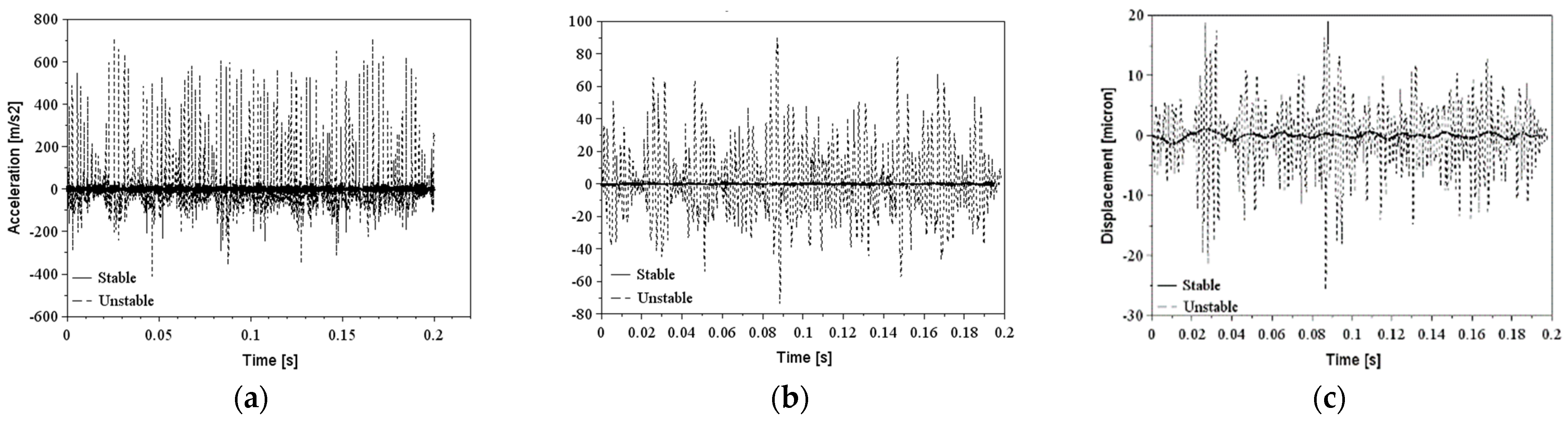
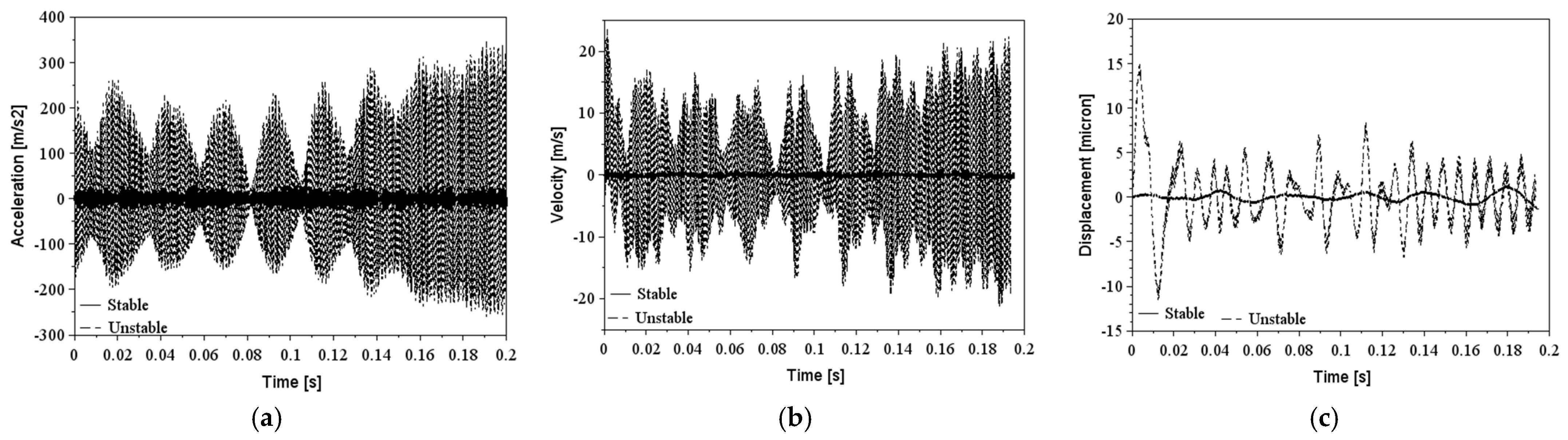
Figure 10,
Figure 11,
Figure 12 and
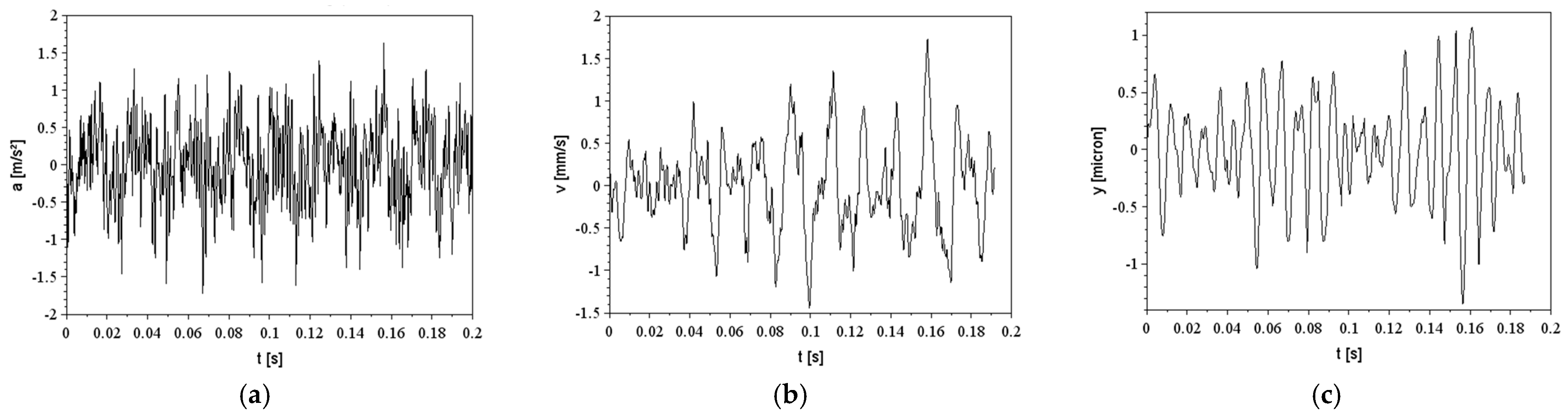
Figure 13 show the experimental results of the acceleration signal that was processed relative to velocity and displacement in the time domain for the unstable and stable cutting conditions of all tools.
The shape of the signal is complex and does not follow a pattern, but the main analysis was based on the amplitude of the displacement signal for each tool. The unstable amplitudes of steel, carbide, and Silent tools (RMS acceleration amplitude higher than 300 m/s
2) are substantially higher compared to the stable ones (RMS acceleration amplitude lower than 50 m/s
2), except for the ID bar that did not show significant amplitudes relative to the long overhangs (RMS acceleration amplitude lower than 3 m/s
2); because of this, there are no unstable signals in
Figure 11.
For the cutting operation, the analysis demonstrated that the frequency of the tool at 725.15 Hz caused higher amplitudes for the TMD than ID for both maximum overhangs. In contrast, in stable conditions, the ID can minimize the deflection of the tool by around five times that of the TMD tool. The resultant roughness values follow the same behavior of the displacement of the tip; when the roughness values are under 0.8 µm, the tools were stable contrary to the roughness values, and this limited their instability during the cutting process.
The operational range of the ID is slightly higher than the TMD, which makes the tool more flexible for cutting long and short overhangs; this avoids the need to change the tool during the process and saves time by limiting the changes made to the tool’s setup.
4. Discussion
Table 3 is an important reference for guiding the selection of tools for a certain operation. It describes the exact overhang limits for tools with different structural configurations and dynamic properties. If we assume that short overhangs are up to 5 and over, this limit is a long overhang, and we can conclude that the best choice for operations with long holes comprises carbide, the Silent tool, and ID boring bars with a maximum TSC equal to 10.40 mm
−1, 29.09 mm
−1, and 32 mm
−1. This proves the efficiency of the damper mechanisms of carbide due to the higher Young’s modulus of the tool, the tuned mass damper system in the Silent tool, and the multitude of balls inside the cavity of the ID tool that can minimize the vibration amplitude of the tool during internal turning operations with respect to hardened materials. In the same way, for short holes, most tools can be used except for the Silent tool, which cannot operate in short overhangs at TSC ≤ 7.81 mm
−1. Another point to be mentioned is that when
Table 2 and
Table 3 are compared, the efficiency of the ID with respect to forced vibrations (during cutting) is superior compared to the TMD in free vibration conditions. This can be explained by the dynamics of the bouncing balls as the excitation amplitude increases and more balls are activated within the cavity to decrease the tool’s vibration amplitude. When a ball is actively participating in the suppression of a tool’s vibration, it performs an approximately circular motion in the cavity. In other words, the ball is not spinning purely on the wall of the cavity but bounces over it as it moves along a non-smooth circular path.
Studying the influence of tool overhang on the tool dynamic stiffness,
Figure 6 indicates that as the TSC of the tools increases from TSC of 1.68 mm
−1 to TSC of 45.56 mm
−1, the natural frequency for all tools decreases significantly, i.e., the carbide boring bar reduces the frequency from 4630 Hz to 640 Hz, which results in a decrease in the static stiffness for all tools of at least eight times by using Equations (3) and (4). Then, in long overhangs, the tool is more vulnerable to chatter than in short overhangs. After this analysis, to avoid undesirable vibrations with a TSC of over 13.50 mm
−1, it is necessary to construct an antivibration system in the tool in order to increase the damping ratio of the tool and consequently, the dynamic stiffness of the tool. The better choice for that is the Silent tool and the ID bar, which activate the damping system of the tool with respect to forced vibrations.
Table 3 and the excitation signals shown from
Figure 10 to
Figure 13 are a set of data that illustrate the vibration amplitude achieved by different boring bars in stable overhangs. It is possible, therefore, to observe that the signals are periodic, and even in the time range of 0.20 s, the behavior of the signal is repeated throughout all tests. The standard, carbide, and TMD boring bars are the bars with the highest vibration amplitude in relation to the ID boring bar.
It is possible to verify that among all the bars tested, the acceleration amplitudes in the stable cutting regime are similar. It is important to remember that the variables that cause excitation at the tool’s tip are, in general, the dynamic parameters of the tool, which are completely dependent on time. Therefore, to reduce the vibration amplitude of the system, it was necessary to modify the inertial and elastic conditions of the tool. These modifications may cause an increase in the damping capacity due to the tungsten carbide, the added mass (TMD bar), and the spheres (ID bar). In this manner, the vibrational energy produced by the harmonic movement of the tool is significantly reduced, and the vibration spectrum becomes smoother [
66].
Using the ID boring bar—where the total length of the tool was out of the clamp system—with an overhang limit TSC = 57.92 mm−1, no abrupt increase in the acceleration signal was detected. However, for this condition, roughness increased abruptly when the bar exceeded TSC = 32 mm−1, where the unstable regime was present. The most accepted hypothesis for explaining how roughness grew significantly without growth in acceleration comes from the vibration theory: for simple harmonic motions, acceleration is proportional to the displacement amplitude, and it is proportional to the square of the frequency. In that case, the acceleration amplitudes can be equal for short and long overhangs, as it was experimentally experienced, but the displacement amplitudes exhibit a different behavior because of their different natural frequencies. Hereafter, one can conclude that the ratio of the roughness is reciprocally proportional to the ratio of the square of the natural frequency of the tool.


