Article

Effect of the Sintering Conditions on the Neck Growth during the Powder Bed Fusion with Electron Beam (PBF-EB) Process

Department of Management and Production Engineering (DIGEP), Integrated Additive Manufacturing Center (IAM@PoliTo), Politecnico di Torino, Corso Duca degli Abruzzi 24, 10129 Torino, Italy
*
Author to whom correspondence should be addressed.
J. Manuf. Mater. Process. 2023, 7(2), 55; https://doi.org/10.3390/jmmp7020055
Submission received: 31 January 2023 / Revised: 23 February 2023 / Accepted: 27 February 2023 / Published: 1 March 2023
(This article belongs to the Special Issue Progress in Powder-Based Additive Manufacturing)

Abstract

:
A distinctive characteristic of the powder bed fusion with electron beam (PBF-EB) process is the sintering of the powder particles. For certain metallic materials, this is crucial for the success of the subsequent step, the melting, and, generally, the whole process. Despite the sintering mechanisms that occur during the PBF-EB process being similar to well-known powder metallurgy, the neck growth rates are significantly different. Therefore, specific analyses are needed to understand the influence of the PBF-EB process conditions on neck growth and neck growth rate. Additionally, some aspects, such as the rigid body motion of the particles during the sintering process, are still challenging to analyze. This work systematically investigated the effects of different particle diameters and particle diameter ratios. Additionally, the impact of the rigid body motion of the particles in the sintering was analyzed. This work demonstrated that the sintering results significantly depended on the EB-PBF process conditions.

1. Introduction

Powder bed fusion additive manufacturing processes can easily produce components with complex geometries by adding thin layers of materials. Among the different powder bed fusion processes, the powder bed fusion with electron beam (PBF-EB) is characterized by the sintering of unmelted material [1]. The process is conducted in a vacuum environment. After raking a thin layer of powder, this is preheated in two steps. After preheating, the cross section of the component is melted. Before distributing a new layer of powder, this is post-heated or cooled to balance the amount of energy supplied at each layer. The energy is balanced so that the temperature of the processing environment is retained to an adequate value for the processed material.
The high temperature inside the build chamber, the preheating, and the post-heating promote the formation of bridges of materials among the powder particles forming the layer. The formation of bridges is usually referred to as sintering and the bridges are called necks. The neck dimension defines the thermal and electrical conductivity [2] and is usually fine-tuned to prevent the “smoke” phenomenon [3]. The “smoke” is usually caused by the accumulation of negative electrostatic charges in the powder particles that produce a repulsion and the expulsion of the powder particles from the powder bed [3]. By increasing the electrical conductivity, the neck between the powder particles allows the dispersion of the negative charge.
The physical mechanisms participating In the neck formation during the PBF-EB are equivalent to those occurring during the sintering belonging to powder metallurgy processes [4,5]. These mechanisms consist of volume diffusion from different sources (Dv), grain boundary diffusion (DGB), surface diffusion (Ds), vapor diffusion (Dvap), and viscous flow or rigid motion of the particles (η) [6]. The difference between the traditional sintering and the sintering in PBF-EB is the time scale [7,8]. The neck growth ratio is higher and more similar to the one in field-assisted sintering technology (FAST), with a large neck and high densification reached in seconds or minutes [9]. However, with respect to FAST, the PBF-EB process is conducted under a vacuum, and the temperature fields are sensibly changed during the sintering in PBF-EB.
For these reasons, investigating the sintering phenomena during the process is complex and usually approached by a trial and error approach [10]. Experiments on the sintering during PBF-EB were reported in [1,11,12]. The results were influenced by the permanence of the powder at high temperatures for a long period, which is not representative of a typical working condition of PBF-EB. In addition, the findings were valid only for the investigated alloys.
An alternative approach to the experiments is the use of numerical models. In this regard, only a few works were found in the literature [8,13]. Yan et al. [13] proposed the use of a phase field (PF) simulation framework. The simulations were performed for a short time step and neglected for the whole duration of the process with the corresponding temperature field variation. The PF framework proposed by Rizza et al. [8] introduced a representation of the working conditions of the PBF-EB process, including temperature evolution and working time. The model proposed by Rizza et al. [8] was validated against an experiment with a good estimation of the neck radius.
However, both models neglected to consider the influence of the particle diameter and diameter ratio on the neck radius/growth. Moreover, the rigid body motion (RBM) of the particles during the sintering has been neglected. However, this last assumption is common in the literature because the implementation of RBM is challenging.
Because of that, in most cases, the RBM is neglected [8,13,14,15,16]. Other works have used an advection term to implement the RBM [17,18,19,20,21,22,23,24,25]. However, the simulations were performed using parameters with numerical values that do not involve any physical measurement or relationship with the sintering process conditions.
The current work proposes the use of several sets of PF simulations to investigate the effect of the particle dimension and the RBM constants on the neck dimension and growth ratio. The analyses are performed considering the characteristic sintering conditions of the PBF-EB process. After a sensitivity analysis, therefore, the fine-tuning of the RBM constants is driven by experimental observations.

2. Materials and Methods

The simulation of sintering during the PBF-EB process was conducted using a PF framework. PF allows the simulation of the system’s evolution without tracking the interface position or imposing any boundary conditions. In the PF model, the evolution of the system is described by conserved and non-conserved variables. Conserved variables bring information about the local composition of the system, such as the density or molar fraction of the system. Non-conserved variables bring information about the local structure of the system or the orientation in space. These could also be used to distinguish the different powder particles.
In the PF model, the system evolves toward the reduction in the system’s free energy. This energy is a function of conserved and non-conserved variables. The formulation of the system-free energy adopted in the current work was proposed by Wang [17] and is reported in Equation (1):
F = f c , η i + 1 2 k c c 2 + 1 2 i k η i η i 2 dV
The free energy of the system is the sum of three parts. The first term (f(c,ηi)) represents the bulk free energy. The second and the third represent the excess of energy at the solid vacuum interface and the particle boundaries, respectively. In Equation (1) kc and kηi represent two coefficients used to scale the gradient of the conserved and non-conserved variables, respectively. A detailed description of these terms can be found in [8]. The system-free energy of Equation (1) is a function of the conserved variable c and the non-conserved variable η. In the current work, c represents the density of the system. It assumes a value of 1 inside the solid material and 0 outside. The non-conserved variable η represents the system’s morphology and is used to identify the powder particles uniquely. It assumes a value of 1 inside the ith particle and 0 over the rest of the domain. The evolution in time of the conserved and non-conserved variables is described by the Cahn–Hilliard and Allen–Cahn equations, reported in Equations (2) and (3), respectively.
c ( x , t ) t = · M δ F δ c ( x , t )   -   c t v adv i
η i t x , t = L δ F δ η i ( x , t )   -   · η i v adv i
Both Equations (2) and (3) are made of two parts. The first represents the atom mobility, related to the diffusion of atoms during the sintering phenomena. In Equation (2), the term M represents the concentration mobility tensor. The term L in Equation (3) represents the order parameter scalar mobility. Further details about this part can be found in [8]. The second term is related to the mobility of the particles. vadvi represents the advection velocity of the ith particle toward the other particles. The formulation adopted in the current work was first proposed by Wang [17]. The advection velocity is mainly composed of the translation and rotation of the particle’s center of mass, as highlighted in Equation (4).
v adv = v t i + v r i
In this equation, vti represents the translation velocity, and vri represents the rotation velocity. These quantities are detailed in Equations (5) and (6).
v t i = m t V i F i η i
v r i = m r V i T i   ×   [ x   -   x c i ] η i
mt and mr represent the translation and rotation mobility coefficients. Vi represents the volume of the particle. x and xci represent the position vector and the position of the center of mass of the particles, respectively. Fi and Ti represent the force and the torque acting on the particles, respectively. These are evaluated with a volume integration, as reported in Equations (7) and (8)
F i = V d F i
T i = V x   -   x c i   ×   d F i
dFi represents the force density between the particles. The formulation of this force was proposed by Wang [17] and is reported in Equation (9).
d F i = k j i ( c c 0 ) η i η j η i   -   η j d 3 x
k and c0 represent the stiffness constant and the equilibrium concentration, respectively. The product ⟨ηiηj⟩ is defined in Equation (10).
η i η j = 1 for   η i η j     c GB 0 for   η i η j   <   c GB
where cGB is a threshold concentration value that locates the grain boundary interface of the particles.
These equations were implemented in the multi-physics object-oriented simulation environment (MOOSE) [18,19], an FEM simulation environment developed at Idaho National Lab. While the Allen–Cahn is directly implementable in MOOSE, the Cahn–Hilliard is a fourth-order differential equation that can be implemented using the split form, reported in Equations (11) and (12).
c t = M μ   -   c i v adv i
μ = F c   -   κ c 2 c
where μ represents a supporting variable. Further details about the implementation of these equations are reported in Ref. [8].
A series of simulations were conducted to investigate different parameters. PF simulation considered only bi-dimensional simulations to reduce the computational power [20].

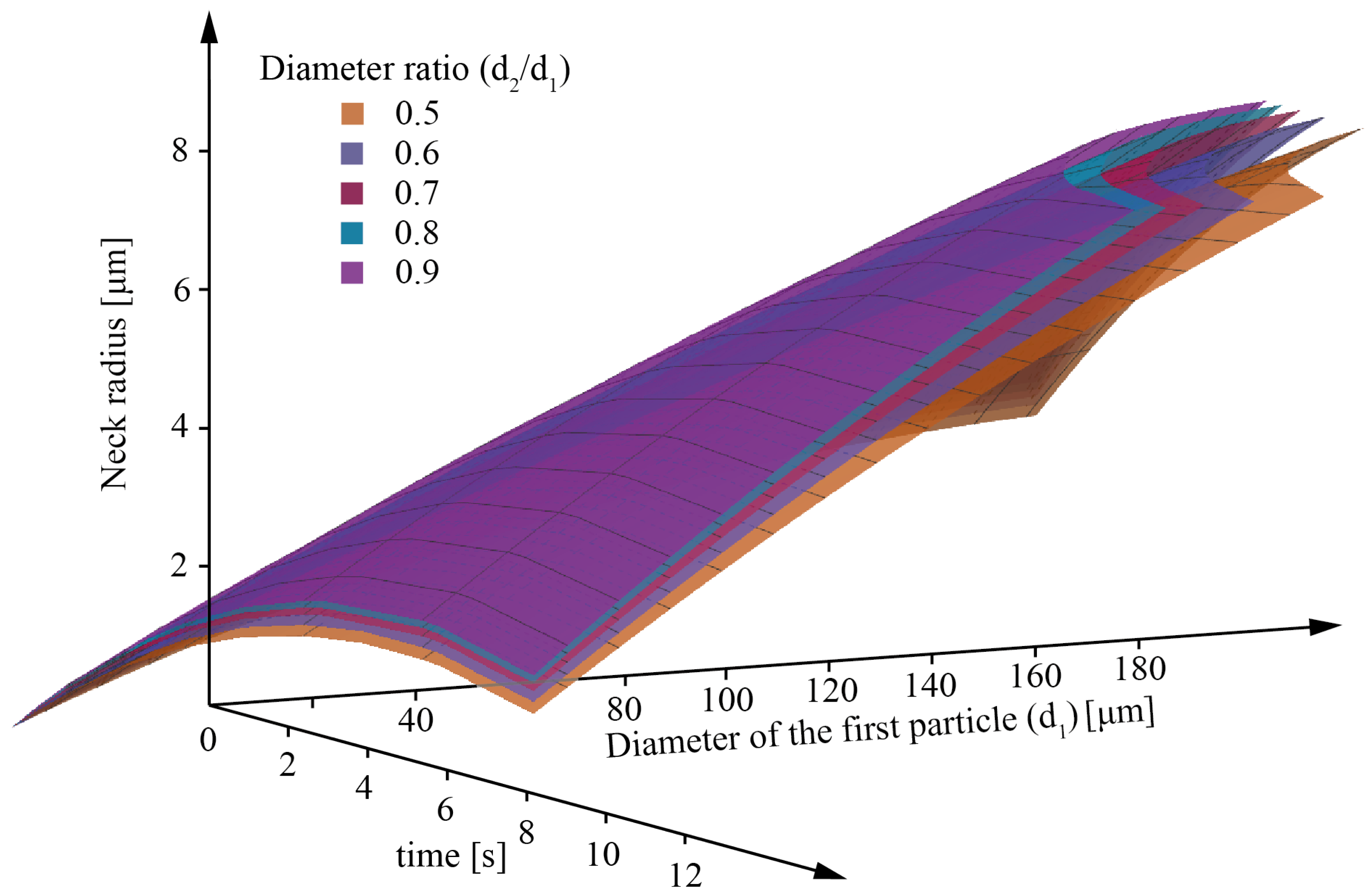
2.1. SET A: Influences of Particle Diameter and Particle Diameter Ratio on the Neck

SET A collects all simulations conducted to investigate the influence of particle diameter and particle diameter ratio on the neck among the particles and the neck growth ratio. In this case, the contribution of the RBM of the particles was neglected.
Only couples of powder particles were considered. The diameter of the first particle (d1) is the particle with the larger diameter in the couple and varied between 80 μm and 140 μm in steps of 15 μm. The diameter of the second particle (d2) varied accordingly to obtain a diameter ratio d2/d1 from 0.5 to 0.9 in steps of 0.1. The examined factors were, therefore, the diameter of the first particle and the diameter ratio. The full factorial design of experiment (DoE) plan is reported in Table 1.
The dimensions of the domain were varied according to the dimensions of the powder particles couple. In particular, the height of the rectangle was set as equal to the diameter of the largest powder particle, and the base was chosen to be equal to the sum of the powder particle diameters. In addition, the size of the domain was increased symmetrically by 10 μm to avoid the boundary effect on material diffusion. A mesh dimension of 1 μm was adopted at the beginning of the simulation and was automatically adjusted at the particle boundary [21]. The elements adopted for the mesh were quadrilateral elements with four nodes (QUAD4).
These simulations were carried out for 9.5 s. The temperature was imposed over the domain and modelled according to Equation (13), adapted from [8].
T t = 845 + int t 0.38 17.12           0   <   t     9.5  
The material properties adopted for the simulations are reported in Table 2.
The influence of the factors under consideration was investigated using the analyses of variance (ANOVA). From these results, the response surfaces depended on the investigated factors that were obtained. These analyses were conducted using the software Minitab 17.

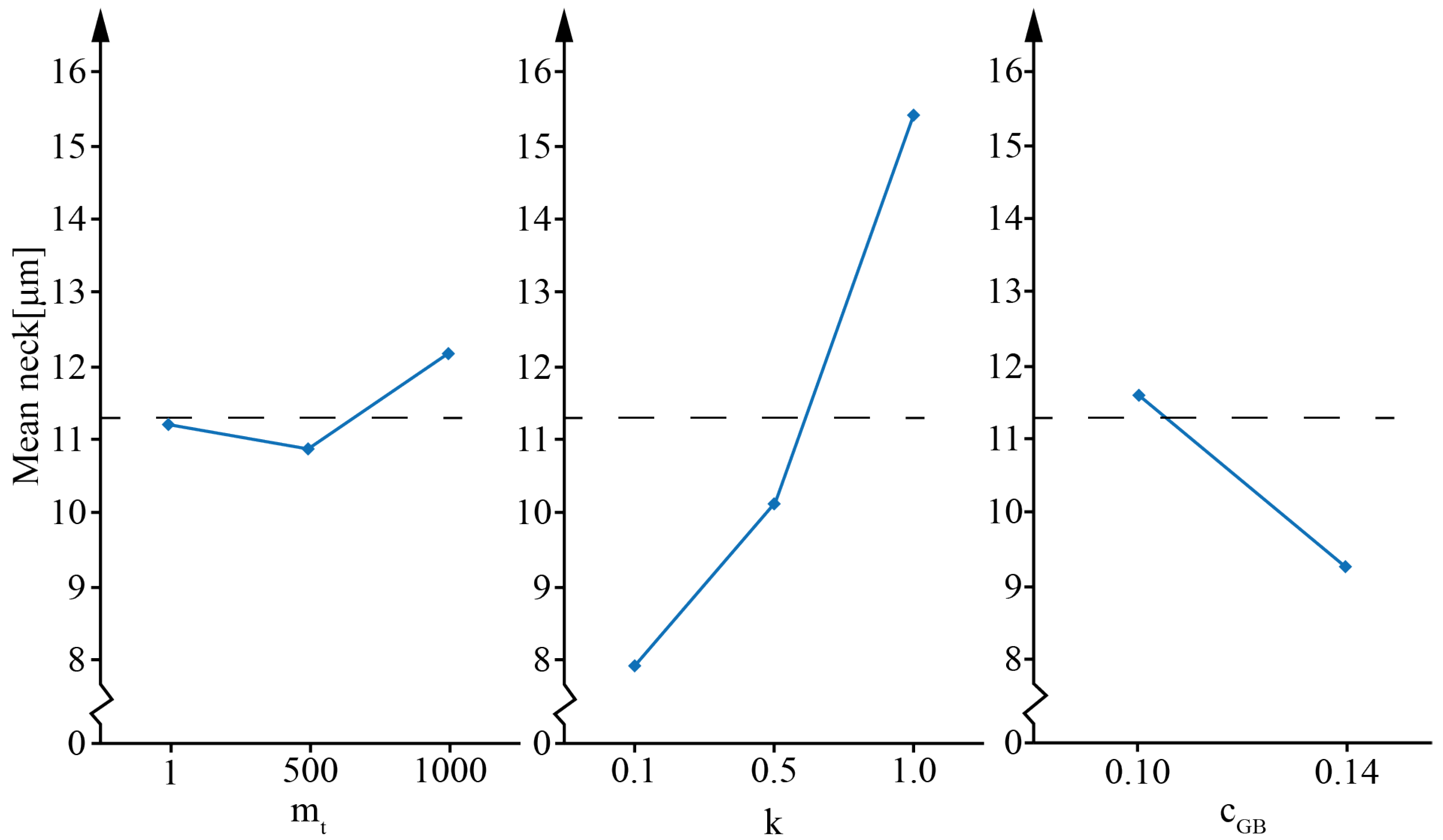
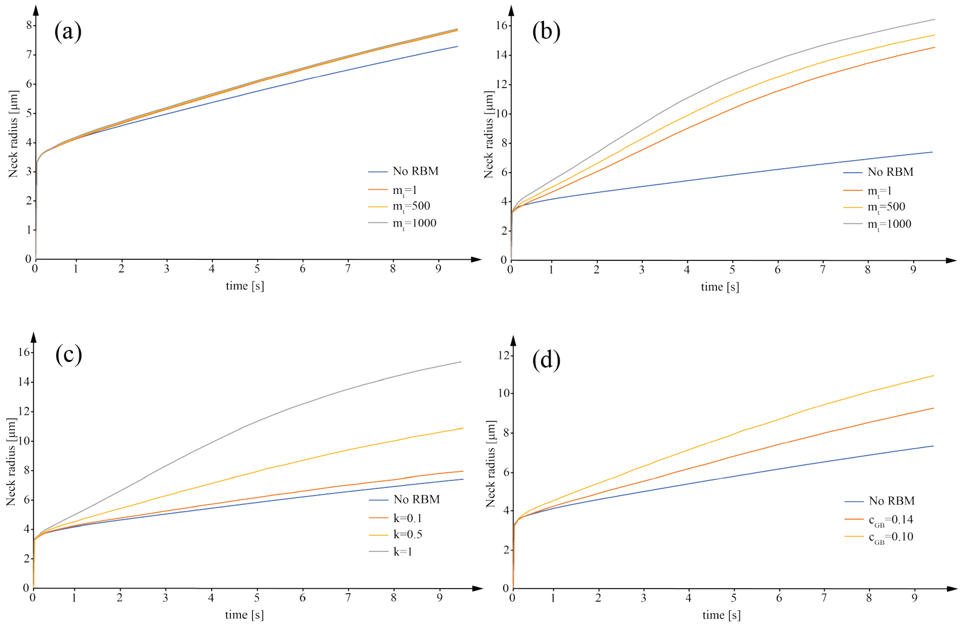
2.2. SET B: Influences of RBM on the Neck

SET B collects all the simulations conducted to investigate the influence of the RBM parameters by varying only the parameters related to the RBM of the particles.
It should be considered that the rigid motion of powder particles during sintering is governed by many parameters, such as the threshold concentration (cGB) (Equation (10)), the equilibrium concentration (c0) (Equation (9)), the stiffness constant (k) (Equation (9)), the translation mobility (mt) (Equation (5)), and the rotation mobility (mr) (Equation (6)).
Under the hypothesis of perfect and smooth spherical particles, the contribution due to the rigid rotational motion (second term in Equation (4)) can be neglected [24].
According to Ref. [17], the equilibrium concentration c0 can be considered 1. cGB, k, and mt were varied in a reasonable range, obtaining four sets of simulations (Table 3).
The simulations were conducted considering bi-dimensional simulations of circular (spherical in three dimensions) powder particles. A rectangular domain with dimensions of 170 μm × 90 μm was considered. The mesh dimension was set as equal to 1 μm and the elements adopted were quadrilateral elements with four nodes (QUAD4).
Two Ti6Al4V powder particles with a diameter of 80 μm were considered. The material properties adopted for the simulations are reported in Table 1. The temperature of the system was varied according to Equation (13).
After identifying the effect of the variables on the particles’ RBM, the results were adopted for experimentally analyzing the sintering behavior during the PBF-EB process. With this aim, the experimental approach proposed in Ref. [8] was used.

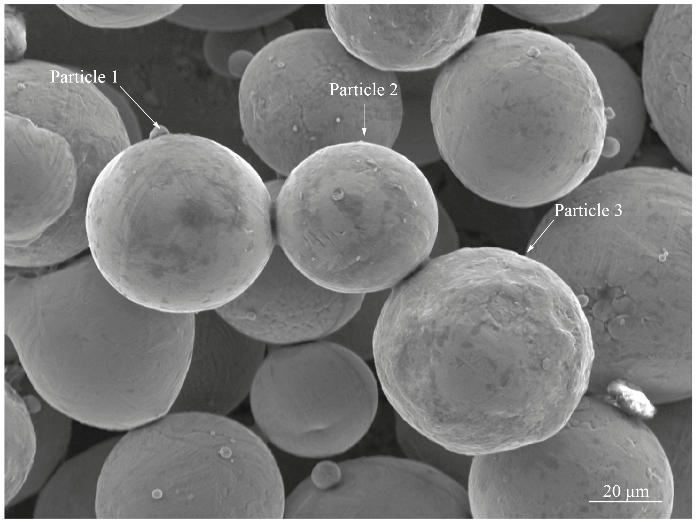
2.3. SETs C and D: Tuning Based on Experimental Data

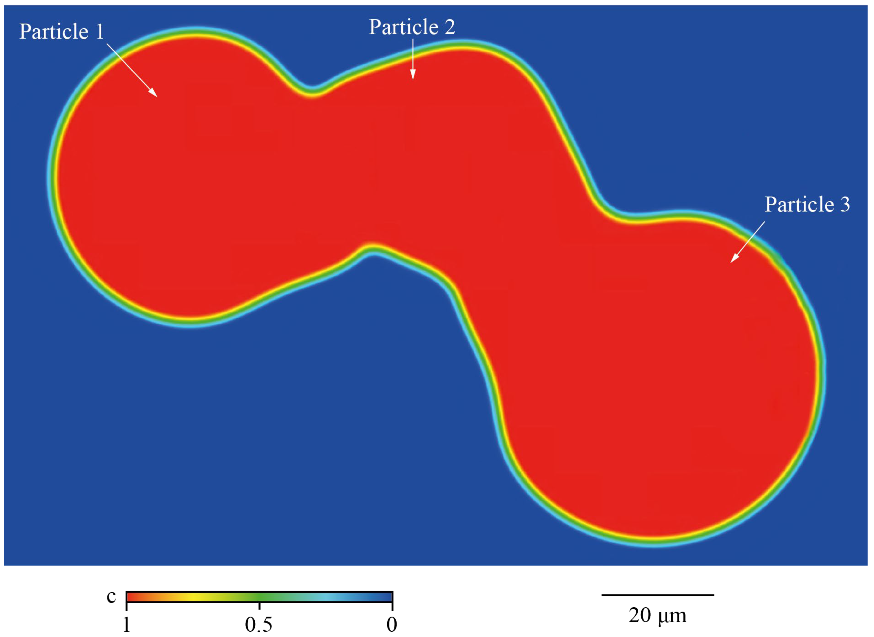
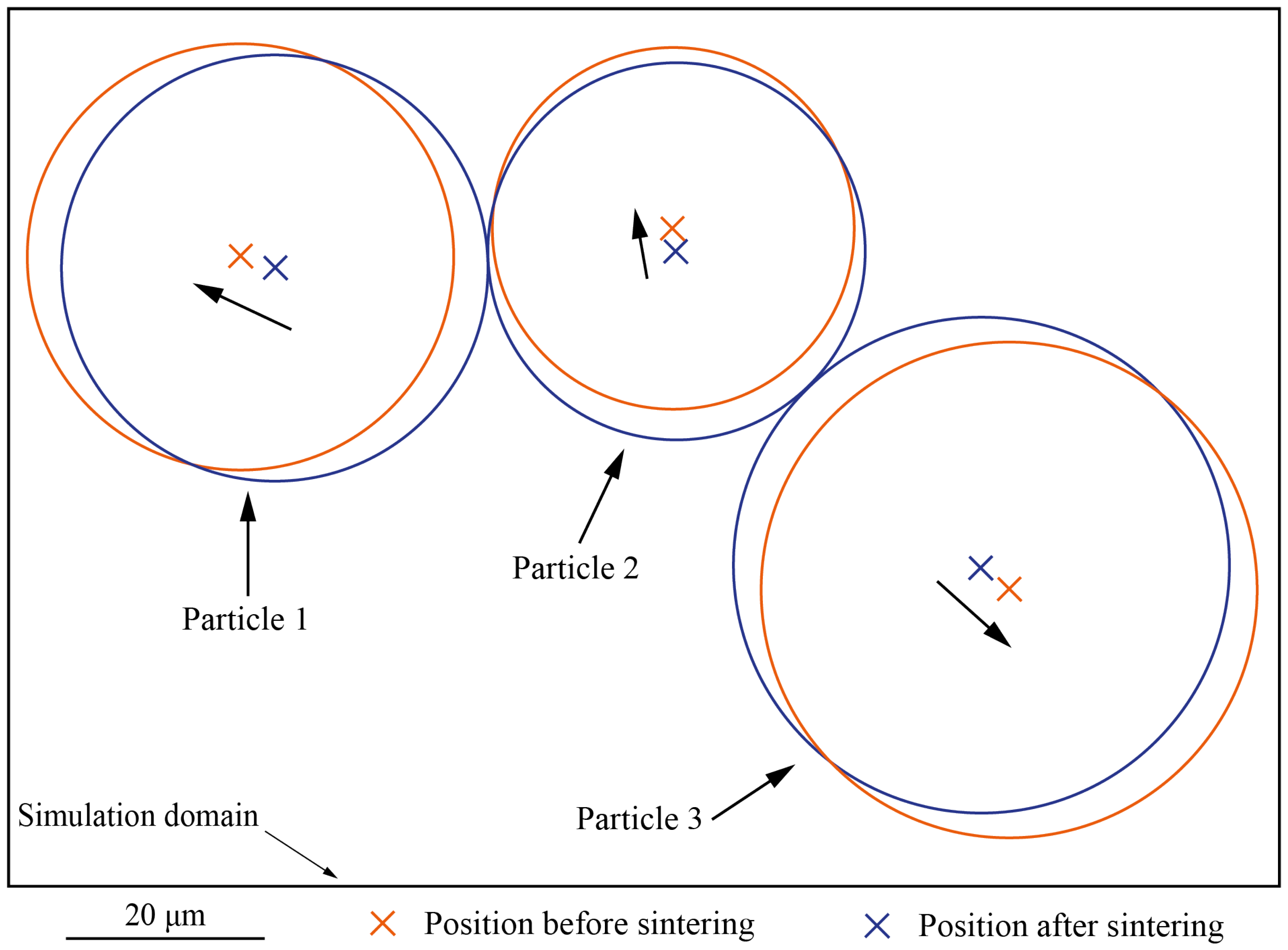
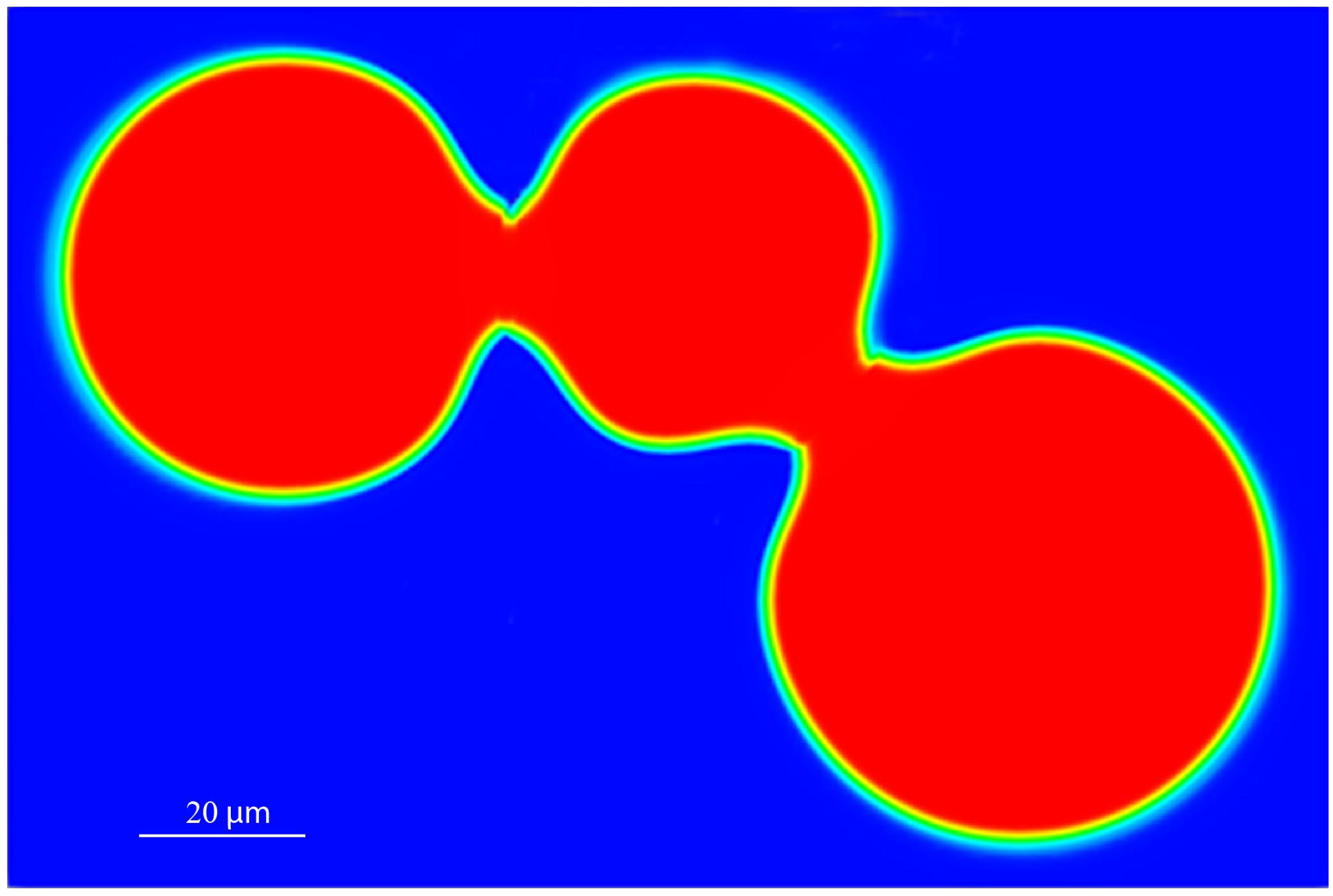
The experiment consisted of the deposition of three layers of powder, which were sequentially heated by the electron beam up to 1131 K to obtain the typical sintering degree achieved during a PBF-EB process. Before starting the powder distribution, the start plate was heated at 1131 K. For conduction from the hot start plate, after distribution, the powder layer reached the temperature of 982 K, causing the adhesion of the powder to the start plate. During the subsequent beam passages, the powder temperature linearly increased up to 1131 K. After heating the last layer, the sintered powder was cooled to room temperature using a helium flow. The experiment was performed in an Arcam A2X machine (Arcam AB, Mölnlycke, Sweden), a PBF-EB system. After the cooling, a sample of the start plate with the sintered powder on top (a cube with a 10 mm edge) was extracted using a wire electrical discharge machining (EDM). This sample was inspected using an SEM (Philips XL30 ESEM, Amsterdam, The Netherlands,), and a trio of particles connected by a sintering neck were extracted. The ImageJ software was adopted to inspect the images obtained with the SEM and measure the dimension of the powder particles and the neck among the particles.
From these data, a set of simulations was conducted to identify a suitable combination of cGB, k, and mt that produces a neck dimension equivalent to that identified experimentally (SET C). The variables were varied according to the previous result from SET B.
The second set of simulations was conducted to identify the proper position of the centers of the powder particles before the translation owed to the RBM during sintering (SET D).
For all these simulations, the material parameters are reported in Table 1. The temperature model adopted for simulating the thermal conditions during the experiment was obtained from the measures collected by the thermocouple positioned below the start plate (Equation (14)). The temperature of the powder particles increases linearly during preheating, due to heat transmitted from the substrate (the start plate) and the energy provided by the electron beam. The start plate operates as a heat accumulator that contributes to maintain a constant temperature of 1131 K. The preheating was performed for 9.5 s, while the temperature of 1131 K was maintained at a constant during the processing of the three layers for 60 s. After this time, temperature decreases to the environment temperature with a parabolic profile.
T t 982 + 15.68 t   0 t 9.5 1131   9.5 < t 60 2.75 10 5 t 60 2 0.27 t 60 + 1131   t > 60
The simulation domain was 152 μm × 101 μm and was adopted for all the simulations. A mesh size of 1 μm was assumed and automatically adjusted at the particle boundary interface.

3. Results and Discussion

3.1. Influences of Particle Diameter and Particle Diameter Ratio on the Neck (SET A)

Table 4 summarizes the results from SET A. For all the diameter ratios, an increase in the diameter of the first particle from 80 μm to 140 μm produced a neck radius that is always approximately 2 μm larger. With the same diameter as the first particles, an increase in the diameter ratio from 0.5 to 0.9 produced a neck radius approximately 1 μm larger. This can be explained by the fact that an increasing diameter ratio corresponds to an increase in the diameter of the second particle and, therefore, a higher diffusion from the second particles. However, the driven particle is the particle with the bigger diameter. Thus, this effect becomes more relevant when the second particle has a comparable dimension or, presumably, when it becomes higher.
Two ANOVAs were conducted to test the influence of the two factors under consideration. For these ANOVAs, a confidence interval of 95% was assumed. Table 5 reports the ANOVA on the diameter of the first particle. A p-value smaller than 0.05 confirms the influence of this parameter on the neck radius.
Table 6 reports the ANOVA on the diameter ratio. The p-value obtained for the diameter ratio proves that this factor is not influential on the neck dimension. The influence of the neck ratio is also investigated, with a visual inspection of the box plot reported in Figure 1.
The Box plot (Figure 1a) shows that the diameter ratio influences the mean of the neck radius. However, this factor does not have a strong influence on the variance because the boxes overlap each other. The overlap of the boxes shows that in the investigated range of the diameter ratio, this factor is not strongly influencing the neck radius dimension obtained at the end of the simulation.
Figure 1b reports the interaction plot adopted to test the presence of interaction among the two factors under consideration. The absence of an intersection among the curves of Figure 1b highlights no interaction among the factors considered. The absence of these interactions and the parallelism among the curve could be interpreted as the possibility of parameterizing the mean neck dimension as a function of the first particle and the simulation time to obtain a response surface iso-diameter ratio. In fact, using the data on the neck radius obtained by SET B every 0.5 s, it is possible to obtain the surface response (Figure 2) that is parameterized as the particles diameter ratio, time, and first particle diameter. The corresponding equations are reported in Table 7.
With the same diameter ratio, the coefficients of the surface response highlight a strong dependence of the neck radius on the simulation time and the diameter of the particles. On the contrary, the second order coefficients such as d12 or t⋅d1 have a reduced impact on the neck radius dimension.

3.2. Influences of RBM on the Neck (SET B)

Table 8 summarizes the dimension of the neck radius obtained at the end of the simulations conducted, considering the RBM parameters reported in Table 3 for set 1, set 2, and set 3. Table 9 summarizes the neck radius obtained from simulations of set 4 of Table 3. For comparison, a simulation was conducted considering the same particle dimension, material properties, and temperature evolution but neglecting the particles’ RBM. The neck radius obtained at the end of this simulation was 7.34 μm.
It can be noticed that the RBM strongly influences the neck radius and hence the neck growth ratio. When the RMB is considered, the neck radius is significantly larger. The effect of each parameter on the neck size is reported in Figure 3. The most influential parameter is k. An increase in k and mt produces a larger neck dimension. cGB has an opposite trend.
Figure 4 shows the neck growth ratio obtained from the simulations conducted with the parameters reported in Table 3.
For k = 0.1 (Figure 4a), mt does not seem to strongly affect the neck radius evolution, even if it is three orders of magnitude higher. For k = 1, the variation of mt becomes significant (Figure 4b). In fact, fixing mt and cGB (Figure 4c) (set 3 of Table 3), the increase in k of an order of magnitude produces a neck radius at the end of the simulation that is nearly twice the value for k = 0.1. The neck radius goes from 7.93 μm when k = 0.1 to a neck radius of 15.35 μm when k = 1. These results confirm the trends identified in the main effect plot (Figure 3). This behavior is explained by the role of k and mt in Equations (5) and (9). A larger value of k combined with a larger value of mt produce a larger value of the translation velocity and, consequently, a higher neck growth ratio. Because of that, an incorrect combination of these two parameters may lead to an unreliable motion of the particles, which generates distortion of the sintered particles.
As expected from Equation (5), the neck growth profile reported in Figure 4a,b suggests an interaction between k and mt. Finally, higher values of cGB (Figure 4d) produce a delay of the RBM and a smaller neck radius and neck radius growth ratio.

3.3. Tuning Based on Experimental Data (Sets C and D)

Figure 5 presents the SEM of the partially sintered powder particles obtained after the PBF-EB job at the conditions described in Section 2.3. In Figure 5, the powder particles are identified as particle 1, particle 2, and particle 3. These particles’ diameters were measured as d1 = 50.8 μm, d2 = 43.4 μm, and d3 = 58.4 μm, respectively. The diameter of the necks between particle 1 and particle 2 and particle 2 and particle 3 was measured to be 12.3 μm and 13.4 μm, respectively.
As mentioned above, the RBM parameters should be selected to avoid distortion of the powder particles during the sintering. An example can be observed in Figure 6, in which k = 1, cGB = 0.14, and mt = 500. Specifically, the distortion can be explained by the fact that a rigid motion of the powder particles also occurs when the temperature drops below the sintering start temperature for the Ti6Al4V (around 800 K [8]). From the result of SET C, a reasonable combination of the RBM parameters was found to be k = 0.03, cGB = 0.14, and mt = 150.
However, to correctly represent the neck growth, it should be considered that the center of the particles observed after the sintering (Figure 5) corresponds to the position assumed by the particles after motion. Therefore, placing the particle in their original position is necessary to perform a more reliable simulation. With this aim, using a trial and error approach, the coordinates of the centers of the powder particles in the simulation were tuned till the differences between the numerical and experimental results reached the minimum. Figure 7 reports the shift of the center of each particle, with respect to the final position (after the sintering), for which the difference between the simulation and the experimental results was almost zero. In particular, particle 1 was moved by 2.1 μm, particle 2 was moved by 1 μm, and particle 3 was moved by 0.9 μm. Comparing the original position of the powder particles to the position after sintering, the powder particles move toward the center of the simulation domain. Moreover, particle 1 and particle 3 move along the same direction, while particle 2 moves along a direction that is approximately orthogonal to the direction of the motion of particle 1 and particle 3.
Figure 8 shows graphically the sintered particles after the tuning (RBM parameters obtained from simulations of the SET C and the position of the particles before sintering identified with the simulations of SET D). The dimension of the necks obtained from the simulation were 12.9 μm and 13.4 μm for couple 1–2 and couple 2–3, respectively, with a negligible deviation from the experimental ones (12.3 μm for couple 1–2 and 13.4 for couple 2–3).

4. Conclusions

For the PBF-EB process, sintering among the powder particles plays a key role. The net created by the neck formation during the sintering helps dissipate the charges and prevents the build-up of negative charge of the powder particles. In addition, the sintered material around the melted area distributes the heat, avoiding heat accumulation or a high thermal gradient that could promote crack formation or stress formation [25]. Therefore, for extremely brittle materials, such as tungsten, the aim of the sintering step is to maintain the entire build above the brittle-to-ductile transition temperature.
The current work uses PF simulations to investigate the influence of the processing parameters on the neck radius among the powder particles. In particular, the effect of the particle diameter and the ratio among the particle diameter was investigated with a DOE. The statistical analyses of the results of the DOE showed that the particle diameter strongly influences the neck radius obtained at the end of the simulation. The ratio between the particle diameters, in the range of the investigated values, has less influence on the neck. The particle diameters ratio has been selected to parameterize the response surfaces models of the neck growth as a function of the diameter of the first particle and the time of sintering (temperature evolution).
When the mechanical aspects of particle motions are considered in the sintering model, it is crucial to consider two aspects properly. The first one is the values of the constants describing the RBM of the powder particles during sintering. Preliminary analyses showed the following:
  • The interaction of mt and k strongly influences the neck radius.
  • The stiffness constant significantly influences the neck radius dimension.
  • A growing value of the threshold concentration (cGB) produces a smaller value of the neck radius due to a delay in the RBM of the particles.
The identified values were found to be dependent on the temperature load and, therefore, from the PBF-EB process. In particular, these values were found to be different from the literature values. However, the literature models were far from describing the sintering process in PBF-EB.
The second aspect is the initial position of each particle center. In this work, this second aspect has been addressed through fine-tuning driven by experimental data on sintering.
Once the RBM constants were established, a more reliable simulation could be performed by considering the actual shape of the particles and the initial layout of the particles as representative of the powder bed. For the PBF-EB process, the processability of non-spherical particles has been demonstrated [25]. In this case, the RBM analysis should also consider the contribution of a rotation of the particle’s center of mass. This motion is derived from a torque created by asymmetric force densities generated during the sintering of particles with an irregular or asymmetric shape [24]. Regarding the initial layout, reliable information could be obtained by choosing a larger domain (thousand particles) in which the geometrical feature could be described by advanced measurements such as computed tomography.

Author Contributions

Conceptualization, M.G. and G.R.; methodology, M.G. and G.R.; software, G.R.; validation, G.R. and P.A.; formal analysis, G.R.; investigation, G.R. and M.G.; resources, L.I.; data curation, G.R.; writing—original draft preparation, G.R.; writing—review and editing, M.G.; visualization, G.R. and P.A.; supervision, M.G. All authors have read and agreed to the published version of the manuscript.

Funding

This research received no external funding.

Data Availability Statement

Data is contained within the article.

Acknowledgments

The authors acknowledge the master’s degree student Simone De Giorgi for the help with the phase field simulations and Lars Nyborg for Figure 5 obtained using the SEM available at the Chalmers University of Technology.

Conflicts of Interest

The authors declare no conflict of interest.

References

  1. He, W.; Jia, W.; Liu, H.; Tang, H.; Kang, X.; Huang, Y. Research on Preheating of Titanium Alloy Powder in Electron Beam Melting Technology. Xiyou Jinshu Cailiao Yu Gongcheng Rare Met. Mater. Eng. 2011, 40, 2072–2075. [Google Scholar] [CrossRef]
  2. Larsson, M.; Snis, A. Method and Device for Producing Three-Dimensional Objects. U.S. Patent US8187521B2, 27 July 2006. [Google Scholar]
  3. Cordova, L.; Sithole, C.; Macía Rodríguez, E.; Gibson, I.; Campos, M. Impact of Powder Reusability on Batch Repeatability of Ti6Al4V ELI for PBF-LB Industrial Production. Powder Metall. 2022, 1–10. [Google Scholar] [CrossRef]
  4. Zhang, J.; Zhang, Y.; Lee, W.H.; Wu, L.; Choi, H.H.; Jung, Y.G. A Multi-Scale Multi-Physics Modeling Framework of Laser Powder Bed Fusion Additive Manufacturing Process. Met. Powder Rep. 2018, 73, 151–157. [Google Scholar] [CrossRef] [Green Version]
  5. Sahoo, S. Consolidation Behavior of Metal Powders in Laser Additive Manufacturing. Met. Powder Rep. 2021, 76, 6–9. [Google Scholar] [CrossRef]
  6. Kang, S.J. Sintering; Elsevier Ltd.: Oxford, UK, 2005; ISBN 0750663855. [Google Scholar]
  7. Rizza, G.; Galati, M.; Iuliano, L. Simulating the Sintering of Powder Particles during the Preheating Step of Electron Beam Melting Process: Review, Challenges and a Proposal. Procedia CIRP 2022, 112, 388–393. [Google Scholar] [CrossRef]
  8. Rizza, G.; Galati, M.; Iuliano, L. A Phase-Field Study of Neck Growth in Electron Beam Powder Bed Fusion (EB-PBF) Process of Ti6Al4V Powders under Different Processing Conditions. Int. J. Adv. Manuf. Technol. 2022, 123, 855–873. [Google Scholar] [CrossRef]
  9. Weston, N.S.; Thomas, B.; Jackson, M. Processing Metal Powders via Field Assisted Sintering Technology (FAST): A Critical Review. Mater. Sci. Technol. 2019, 35, 1306–1328. [Google Scholar] [CrossRef]
  10. Galati, M.; Defanti, S.; Saboori, A.; Rizza, G.; Tognoli, E.; Vincenzi, N.; Gatto, A.; Iuliano, L. An Investigation on the Processing Conditions of Ti-6Al-2Sn-4Zr-2Mo by Electron Beam Powder Bed Fusion: Microstructure, Defect Distribution, Mechanical Properties and Dimensional Accuracy. Addit. Manuf. 2022, 50, 102564. [Google Scholar] [CrossRef]
  11. Gong, X.; Chou, K. Characterization of Sintered TI-6AL-4V Powders in Electron Beam Additive Manufacturing. In Proceedings of the ASME 2013 International Manufacturing Science and Engineering Conference Collocated with the 41st North American Manufacturing Research Conference, MSEC 2013, Madison, WI, USA, 10–14 June 2013. [Google Scholar]
  12. Leung, C.L.A.; Tosi, R.; Muzangaza, E.; Nonni, S.; Withers, P.J.; Lee, P.D. Effect of Preheating on the Thermal, Microstructural and Mechanical Properties of Selective Electron Beam Melted Ti-6Al-4V Components. Mater. Des. 2019, 174, 107792. [Google Scholar] [CrossRef]
  13. Yan, W.; Ma, W.; Shen, Y. Powder Sintering Mechanisms during the Pre-Heating Procedure of Electron Beam Additive Manufacturing. Mater. Today Commun. 2020, 25, 101579. [Google Scholar] [CrossRef]
  14. Kumar, V.; Fang, Z.Z.; Fife, P.C. Phase Field Simulations of Grain Growth during Sintering of Two Unequal-Sized Particles. Mater. Sci. Eng. A 2010, 528, 254–259. [Google Scholar] [CrossRef]
  15. Wang, H.; Biswas, S.; Han, Y.; Tomar, V. A Phase Field Modeling Based Study of Microstructure Evolution and Its Influence on Thermal Conductivity in Polycrystalline Tungsten under Irradiation. Comput. Mater. Sci. 2018, 150, 169–179. [Google Scholar] [CrossRef] [Green Version]
  16. Deng, J. A Phase Field Model of Sintering with Direction-Dependent Diffusion. Mater. Trans. 2012, 53, 385–389. [Google Scholar] [CrossRef] [Green Version]
  17. Wang, Y.U. Computer Modeling and Simulation of Solid-State Sintering: A Phase Field Approach. Acta Mater. 2006, 54, 953–961. [Google Scholar] [CrossRef]
  18. Permann, C.J.; Gaston, D.R.; Andrš, D.; Carlsen, R.W.; Kong, F.; Lindsay, A.D.; Miller, J.M.; Peterson, J.W.; Slaughter, A.E.; Stogner, R.H.; et al. MOOSE: Enabling Massively Parallel Multiphysics Simulation. SoftwareX 2020, 11, 100430. [Google Scholar] [CrossRef]
  19. Lindsay, A.D.; Gaston, D.R.; Permann, C.J.; Miller, J.M.; Andrš, D.; Slaughter, A.E.; Kong, F.; Hansel, J.; Carlsen, R.W.; Icenhour, C.; et al. 2.0-MOOSE: Enabling Massively Parallel Multiphysics Simulation. SoftwareX 2022, 20, 101202. [Google Scholar] [CrossRef]
  20. Dzepina, B.; Balint, D.; Dini, D. A Phase Field Model of Pressure-Assisted Sintering. J. Eur. Ceram. Soc. 2019, 39, 173–182. [Google Scholar] [CrossRef]
  21. Termuhlen, R.; Chatzistavrou, X.; Nicholas, J.D.; Yu, H.C. Three-Dimensional Phase Field Sintering Simulations Accounting for the Rigid-Body Motion of Individual Grains. Comput. Mater. Sci. 2021, 186, 109963. [Google Scholar] [CrossRef]
  22. Roth, T.A.; Suppayak, P. The Surface and Grain Boundary Free Energies of Pure Titanium and the Titanium Alloy Ti6Al4V. Mater. Sci. Eng. 1978, 35, 187–196. [Google Scholar] [CrossRef]
  23. Nemat-Nasser, S.; Guo, W.G.; Cheng, J.Y. Mechanical Properties and Deformation Mechanisms of a Commercially Pure Titanium. Acta Mater. 1999, 47, 3705–3720. [Google Scholar] [CrossRef] [Green Version]
  24. Seiz, M. Effect of Rigid Body Motion in Phase-Field Models of Solid-State Sintering. Comput. Mater. Sci. 2022, 215, 111756. [Google Scholar] [CrossRef]
  25. Ren, X.; Peng, H.; Li, J.; Liu, H.; Huang, L.; Yi, X. Selective Electron Beam Melting (SEBM) of Pure Tungsten: Metallurgical Defects, Microstructure, Texture and Mechanical Properties. Materials 2022, 15, 1172. [Google Scholar] [CrossRef] [PubMed]
Figure 1. (a) Box plot of the neck radius obtained at different diameter ratios of the particle diameters. (b) Interaction plot for the two factors under consideration: diameter of the first particle (d1) and diameter ratio (d2/d1).
Jmmp 07 00055 g001
Figure 2. Surface plot of the neck radius obtained at each diameter ratio and simulation time.
Jmmp 07 00055 g002
Figure 3. Main effect plot of the RBM parameters under consideration on the dimension of the neck radius at the end of the simulation.
Jmmp 07 00055 g003
Figure 4. (a) Effect of the mobility translation (mt) for k = 0.1 and cGB = 0.1; (b) effect of mobility translation (mt) for k = 1 and cGB = 0.1; (c) effect of stiffness constant (k) for mt = 500 and cGB = 0.1; and (d) effect of the concentration threshold (cGB) for k = 0.5 and mt = 500.
Jmmp 07 00055 g004
Figure 5. System of three powder particles adopted to tune the RBM parameters.
Jmmp 07 00055 g005
Figure 6. Powder particles distorted from an inappropriate selection of the RBM parameters.
Jmmp 07 00055 g006
Figure 7. Translation of the particle centers from the estimated position before sintering to the position measured in Figure 5.
Jmmp 07 00055 g007
Figure 8. Result of the simulation conducted considering the RBM parameters obtained from SET C and SET D.
Jmmp 07 00055 g008
Table 1. Full factorial design of experiment plan to investigate the influence of particle diameter and diameter ratio.
d2 (μm)Diameter Ratio (/)
0.50.60.70.80.9
d1 (μm)804048566472
9547.55766.57685.5
1105566778899
12562.57587.5100112.5
140708498112126
Table 2. Material properties of Ti6Al4V adopted for the PF simulations.
PropertyValueUnitsReference
ϑGB10−11m4 J−1 s−1 [13]
γGB0.81J m−2 [22]
γS2.1J m−2[22]
Qs1.19 × 10−19J[13]
D0S9.33 × 10−8m2 s−1[13]
QV3.2 × 10−19J[23]
D0V2.92 × 10−19m2 s−1[23]
Ω 4.051 × 10⁻²⁹m3
Table 3. Numerical values for the rigid body motion parameters (SET B).
SetcGBKmt
10.10.1(1, 500, and 1000)
20.11(1, 500, and 1000)
30.1(0.1, 0.5, and 1)500
4(0.1 and 0.14)0.5500
Table 4. Neck radius for the SET A of simulations measured at the end of the simulation.
d2 (μm)Diameter Ratio, d2/d1
0.50.60.70.80.9
d1 (μm)806.036.406.706.957.16
956.586.987.307.577.80
1107.097.517.858.148.38
1257.568.008.368.668.92
1408.008.468.849.159.42
Table 5. ANOVA to test the influence of the diameter of the first particle (d1) on the neck radius.
SourceDFAdj SSAdj MSF-Valuep-Value
d1 (μm)414.093.5213.59<0.05
Error205.190.26
Total2419.29
Table 6. ANOVA of the influence of diameter ratio on the neck radius.
SourceDFAdj SSAdj MSF-Valuep-Value
Diameter Ratio45.151.291.820.16
Error2014.130.71
Total2419.29
Table 7. Response surface regression equation for each diameter ratio.
Diameter RatioResponse Surface Regression Equation
0.5x = 0.3840 + 0.4793⋅t + 0.0320⋅d1 − 0.0284⋅t2 − 0.0001⋅d12 + 0.0017⋅t⋅d1
0.6x = 0.4300 + 0.5093⋅t + 0.0335⋅d1 − 0.0299⋅t2 − 0.0001⋅d12 + 0.0018⋅t⋅d1
0.7x = 0.4800 + 0.5336⋅t + 0.0345⋅d1 − 0.0311⋅t2 − 0.0001⋅d12 + 0.0019⋅t⋅d1
0.8x = 0.5100 + 0.5530⋅t + 0.0355⋅d1 − 0.0321⋅t2 − 0.0001⋅d12 + 0.0020⋅t⋅d1
0.9x = 0.5400 + 0.5690⋅t + 0.0363⋅d1 − 0.0328⋅t2 − 0.0001⋅d12 + 0.0020⋅t⋅d1
Table 8. Neck radius obtained from simulations of set 1, set 2, and set 3 of Table 3.
Neck Radius (X) (μm)mt
15001000
k0.17.917.937.95
0.5/10.92/
114.5015.3516.38
Table 9. Neck radius obtained from simulations of set 4 from Table 3.
CGBNeck Radius (X) (μm)
0.110.92
0.149.26
Disclaimer/Publisher’s Note: The statements, opinions and data contained in all publications are solely those of the individual author(s) and contributor(s) and not of MDPI and/or the editor(s). MDPI and/or the editor(s) disclaim responsibility for any injury to people or property resulting from any ideas, methods, instructions or products referred to in the content.

