Article

Linear Friction Welding of Abrasion Resistant CPM 15V Tool Steel to an Alloyed Carbon Shovel-Tooth Steel

1
National Research Council Canada, Mining Wear and Corrosion Laboratory, 4250 Wesbrook Mall, Vancouver, BC V6T 1W5, Canada
2
National Research Council Canada, Aerospace Research Center, Montréal, QC H3T 1J4, Canada
*
Author to whom correspondence should be addressed.
J. Manuf. Mater. Process. 2023, 7(2), 51; https://doi.org/10.3390/jmmp7020051
Submission received: 3 February 2023 / Revised: 16 February 2023 / Accepted: 17 February 2023 / Published: 21 February 2023
(This article belongs to the Special Issue Advances in Welding Technology)

Abstract

:
Alloyed carbon steels used in ground engaging tools (GETs), such as shovel-teeth, can withstand high working loads, but their wear resistance is inadequate for abrasive operations in the mining industry. Different approaches to engineer protective surfaces on GETs for improving wear resistance have been developed over the years, but the effectiveness of the applied abrasive resistance layer has been limited by the maximum thickness that can be realized reliably. Considering wear requirements for GETs to reach end-of-life without requiring unscheduled maintenance for after-failure repairs, a minimum thickness of 25 mm has been postulated for the abrasive resistance surface layer, which is roughly four times greater than the thickness of overlays currently manufacturable by weld deposition technologies. Thus, in this study, a novel approach for conceiving thick abrasive surface protection layers—that are unlimited in thickness—on GETs is presented. The method involves applying solid-state linear friction welding and was demonstrated to be feasible for joining abrasive-resistant CPM 15V tool steel to an alloyed carbon steel (extracted from a shovel-tooth). After welding, the integrity of the joints was examined microscopically using optical and scanning electron microscopy to understand the microstructural characteristics, as well as through microhardness and tensile testing to evaluate the performance. A high frequency welding condition was identified that provided integral bonding (i.e., without voids and cracking) at the interface between the CPM 15V tool steel and alloyed carbon shovel-tooth steel. In the as-welded condition, the measured hardness profiles across the joints showed minor softening of both base materials in the heat-affected zone just adjacent to the weld center; this was attributed to over aging of the tempered martensite structures of CPM 15V tool steel and alloyed carbon shovel-tooth steel. The maximum tensile strength of the joint (553 MPa) provides evidence for the viability of linear friction welding technology for joining protective surface materials on GETs.

1. Introduction

Wear is a significant cost factor in the mining industry due to rapid material loss and production interruptions. Materials having good wear resistance in mining applications are usually hard and brittle and, as a result, do not have the mechanical strength and toughness required to withstand the high working load for prolonged times [1]. One of the most effective strategies to meet the conflicting requirements is to apply a highly wear-resistant material on a strong and tough steel base as a localized reinforcement to form a composite assembly.
Hardfacing is one of these most commonly used techniques, e.g., applying weld overlays using laser or arc welding processes. However, for many heavy wear components, such as ground engaging tools (GETs), the effectiveness of the welding overlay is limited because the thickness of the overlay (typically 60–65 wt% WC in NiCrBSi or NiBSi self-fluxing alloy matrix with a hardness of 50–60 HRC) that can be applied by the weld deposition technologies (usually plasma transfer arc welding (PTAW), ~6 mm) is much less than the thickness of materials to be consumed before the end-of-life of the wear component. For example, Figure 1 shows a photo and approximate dimensions of the tip portion of a new shovel tooth used in Canadian oil sands mining. The steel is usually a low-carbon or low-carbon low-alloy steel heat treated to a hardness of around 50–55 HRC. After use, much of the material in the tip will have been worn out, with a reduction of 25–50 mm in thickness and 150–200 mm in length. Ideally, the volume of the applied high wear-resistant material should be equal to or greater than the actual wear volume.
One of such methods for attaching a higher volume of wear-resistant materials is brazing, such as brazing high chromium white cast iron blocks or cemented tungsten carbide tiles on a steel base. However, brazing involves high heat input to the whole assembly, and the heat cycles tend to severely weaken the mechanical properties of the base/substrate materials. Thus, this brazing method is mainly used to produce wear blocks for applications where these blocks are further supported by other structural backing, such as being welded or bolted onto the walls of chutes. Notwithstanding this application, the brazing method is not suited for protecting components under high working loads that require both high strength and toughness.
To innovate bonding of wear-resistant material onto the surfaces of GET materials, an approach using linear friction welding (LFW) was engineered in this study. As a derivate of friction welding processes, LFW is a solid-state material joining technique that involves heat generation through mechanical friction between the contacting interfaces of two workpieces that are moving/reciprocating linearly relative to one another while under an applied compressive force. Unlike conventional fusion welding, no melting of the workpiece materials occurs during LFW, which has provided key advantages [2,3] in the aerospace industry [4] for joining difficult-to-weld materials, such as reactive titanium alloys [5,6,7,8,9,10,11,12,13] and crack-sensitive nickel-based superalloys [14,15,16,17,18,19,20,21,22,23,24]. In LFW, the rapid increase in temperature, at the contact surfaces, locally reduces the deformation resistance of the workpiece materials that then plastically deform under the applied (upsetting/forging) forces and form a solid-state bond. In the case of dissimilar material joints, plastic deformation occurs preferentially from the workpiece with lower strength (or deformation resistance) at the elevated temperatures experienced during LFW [25,26,27,28,29], and bonding has been studied for a broad range of combinations [30,31,32,33,34,35,36].
To date, no published work has been found in the open literature on using LFW for dissimilar joining of wear-resistant materials to GET materials for mining wear applications. However, developing the LFW process to bond this combination of dissimilar materials would be a game-changing innovation for the mining industry for several reasons. First, as the capacity of LFW systems limits only the joint surface area and not the workpiece thickness, there would be no limitation to the layer thickness of the wear-resistant material that could be applied to the GET. In addition, LFW has the capability of near-net shape joining of complex cross-sectional profiles, rendering flexibility for bonding the wear-resistant material to different GET shapes, sizes, and materials. Moreover, the localized and lower temperatures during LFW have the potential to minimize changes to the assembled geometry, microstructure, and properties, such that bonding of the wear-resistant material to the GET may be possible after heat treating these materials separately to achieve their respective optimum properties. Considering these strong motivators, the main objective of this study was to explore the feasibility of joining an exceptionally high wear-resistant material—CPM 15V tool steel—to a GET material—a cast alloyed carbon steel—using LFW and studying the weld integrity by examining the characteristics and properties of the joints.

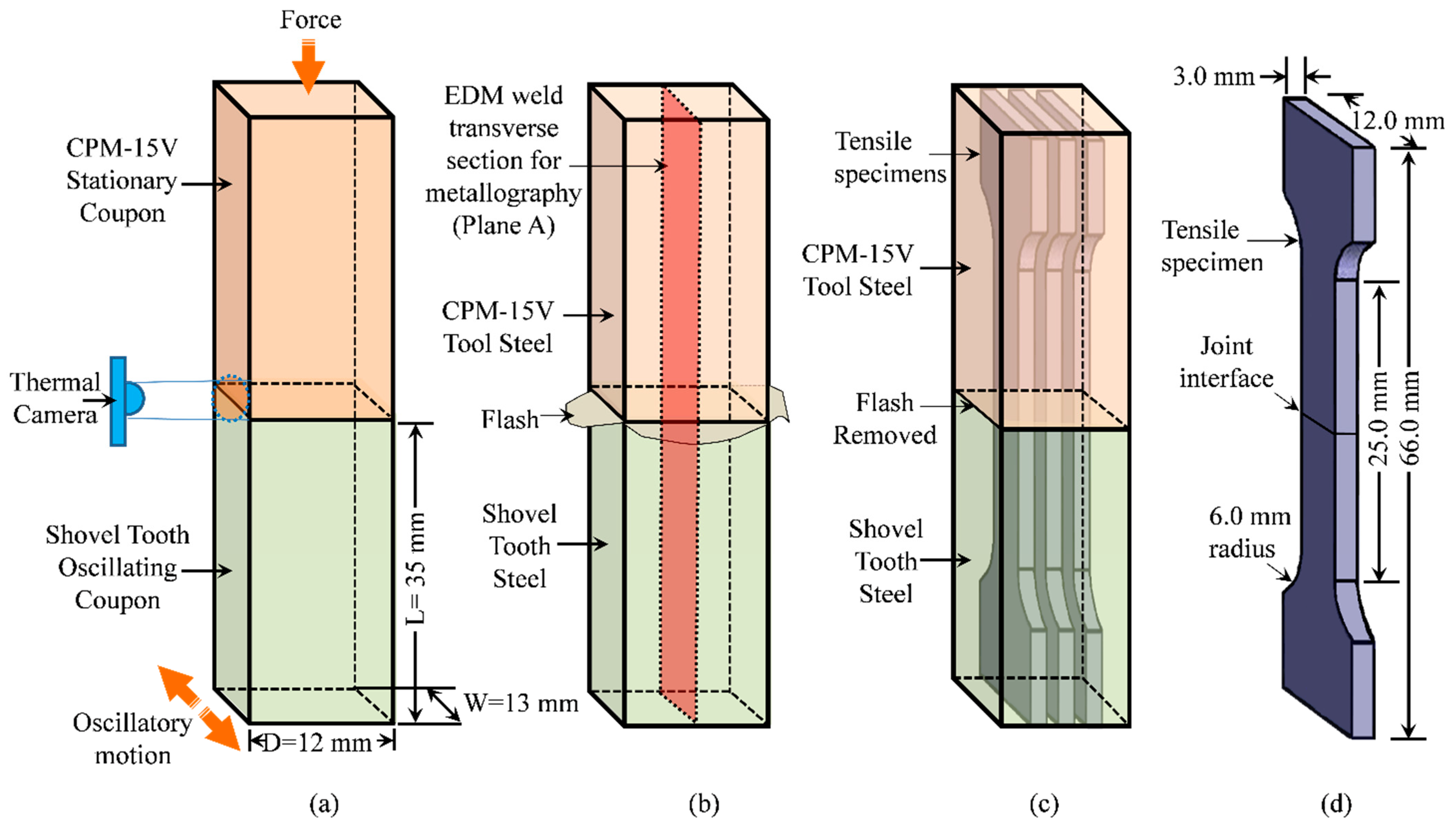
2. Experimental Procedures

In this study, the two materials selected for solid-state joining using LFW were a cast low alloy carbon steel, extracted from a commercial shovel-tooth part, as well as CPM 15V tool steel, fabricated using a combined powder metallurgy production process and subsequent standard mill processing (the Crucible Particle Metallurgy (CPM ®) process) and supplied by Crucible Industries (Solvay, NY, USA). Their chemical compositions are given in Table 1.
The cast shovel-tooth steel was quench-and-temper heat treated according to industrial practice and had a hardness of 53 ± 2 HRC. By contrast, the CPM 15V tool steel was heat treated for high wear resistance using a multi-step procedure that involved (1) austenitizing to obtain adequate dissolution of the alloying elements, (2) hardening to maximize the wear resistance, and (3) tempering to improve/balance the toughness. The austenitizing solution treatment consisted of heating the CPM 15V tool steel in a laboratory furnace to 1150 °C and holding for 30 min. The CPM 15V tool steel was then cooled to room temperature by forced air quenching. Immediately afterwards, the CPM 15V tool steel material was subjected to triple tempering, and each individual tempering stage consisted of heating to 555 °C, holding at temperature for 120 min, followed by forced air quenching to room temperature. After heat treatment, the hardness of the CPM 15V tool steel was 63 ± 2 HRC. The microstructures of the CPM 15V tool steel and the shovel-tooth steel are shown in Figure 2a–d, respectively. The microstructure of the shovel-tooth material was predominately tempered martensite, which is important in manufacturing practice for balancing the combination of properties (e.g., hardness and toughness) required for its industrial application. The microstructure of the CPM 15V steel consisted of a matrix of tempered martensite with uniformly dispersed spherical vanadium carbides (VCs) roughly ~3 µm in diameter.
The coupons of the shovel-tooth steel and CPM 15V tool steel were electro-discharge machined (EDM) to dimensions of 12.0 mm (D) by 13.0 mm (W) by 33.0 mm (L) with a tolerance of 0.02 mm. Prior to LFW, the faying surfaces at the joint interface were lightly sanded using 320-grit sandpaper and subsequently cleaned with ethanol. The MTS LFW process development system (PDS) was used for LFW at the National Research Council Canada’s Aerospace Research Center (Montréal, QC, Canada) that had technical specification as given in [6]. Basically, the MTS LFW PDS system consists of two hydraulic actuators and, in this study—with the chosen configuration illustrated in Figure 3a—the shovel-tooth steel coupon was placed in the lower holder that was oscillated by the in-plane actuator, while the CPM 15V tool steel coupon was held stationary in the top holder to which the forge actuator applied a downward load.
The LFW experiments were conducted in air (without any gas shielding protection) at a room temperature of 22 °C. Keeping all other LFW process parameters constant, as shown in Table 2, two frequency conditions were employed to manufacture the dissimilar materials joint, namely, low frequency (LF) and high frequency (HF). Three repetitions were conducted for each condition.
To monitor changes in surface temperature at the joint interface during LFW, a FLIR SC8300HD thermal camera (Wilsonville, OR, USA) was employed. To guarantee accurate surface temperature readings, the thermal camera underwent blackbody calibration for NIST traceability. Nevertheless, despite the camera’s calibration on a blackbody source, its ability to accurately measure temperatures on the interface of the shovel-tooth steel and CPM 15V joint depends on the actual surface emissivity within the LFW process temperature range. Thus, to determine the average emissivity value, the methodology involved heating the shovel-tooth steel and CPM 15V tool steel coupons to 1100 °C in a furnace and monitoring their actual temperatures using a thermocouple attached to their surfaces. Then, the surface temperatures on the shovel-tooth steel and CPM 15V tool steel coupons were also measured with the thermal camera. By aligning the surface temperature readings from the thermal camera with those from the thermocouple during the cooling process from 1100 °C to 550 °C, the emissivity was calibrated, resulting in an average emissivity of 0.9.
After LFW, transverse sections were extracted from the welds using EDM, as illustrated schematically in Figure 3b. Metallographic preparation of the transverse weld cross-sections (i.e., on Plane A in Figure 3b) involved automated grinding using successively finer SiC papers from 220 grit to 1200 grit and water to render the surface planar and with a 9 µm finish. Then the specimens were polished sequentially on Struers MD-Dur, MD-Dac, and MD-Nap pads (Ballerup, Denmark) using, respectively, 6 µm, 3 µm, and 1 µm diamond suspensions with DP-blue lubricant. To characterize the microstructure of the welds, a polished surface was analyzed using secondary electron (SE) imaging on a Hitachi S 3500 N variable pressure scanning electron microscope (SEM) (Etobicoke, Ontario, ON, Canada) operating at an accelerating voltage of 20 kV. This SEM was also outfitted with an energy-dispersive X-ray spectroscopy (EDS) detector for elemental analysis and mapping.
To prepare the welds for micro-hardness testing, the joints were cold-mounted in resin and mechanically polished to a 1 µm finish using the automated grinding and polishing procedure described above. Vickers micro-hardness testing was guided by ASTM E 384-17 [37] and performed using a Struers DuraScan 80 machine (Ballerup, Denmark) equipped with an automated x–y stage and a fully automated testing cycle (i.e., stage movement, loading, focusing, and measurement). Three hardness profiles were carried out on transverse weld cross-sections (i.e., Plane A in Figure 3b) for each condition at an interval of 0.1 mm with a load of 200 g for a dwell period of 15 s. To avoid the influence of strain fields from neighboring indents, the minimum distance between test points for all measurements was at least three times the diagonal measurement of the indent.
On the basis of ASTM E8M-16a [38] standard as a guide for tensile testing, tensile specimens having a standard sub-size geometry of 25 mm in gage length, 6 mm in width, and 3 mm in thickness were extracted (Figure 3c) and machined (Figure 3d) from the joints. The tensile specimens for each joint were tested at room temperature using an MTS testing frame, with a load capacity of 250 kN that was equipped with a laser extensometer and a non-contact optical 3D deformation measurement system (commonly known as digital image correlation (DIC), Aramis® (GOM-Trillion Quality Systems, (King of Prussia, PA, USA)), as illustrated in Figure 4.
Before the tensile tests, one side of the specimen was marked with two pieces of retro-reflective tape to establish the gage length for the laser extensometer measurements during testing, as shown in Figure 4c. On the opposite side, a white background was first painted, followed by setting a high-contrast random pattern of black speckles (Figure 4b). As the accuracy of the Aramis® DIC system is dependent on the quality of the speckle pattern, verification of pattern recognition was performed prior to tensile testing to ensure proper strain recording along the entire gage length. Tensile tests were carried out until rupture using displacement control at a rate of 0.4 mm/min, corresponding to an average strain rate of 0.015 min−1. Engineering stresses were calculated from the load data obtained from the tensile testing machine, while related strains were calculated using the displacement data from the laser extensometer to obtain the related mechanical properties. A minimum of three specimens was tested for each selected weld condition to determine the average properties, including ultimate tensile strength (UTS), percent elongation (EL), and elastic modulus (E). The deformation captured by the Aramis® system was used to map the 2D strain distribution along the gage length of each specimen. DIC strain distribution maps were used to examine strain localization just prior to rupture. After testing, stereo-microscopy and SEM at 20 keV were used to observe the fracture surfaces of the specimens.

3. Results and Discussion

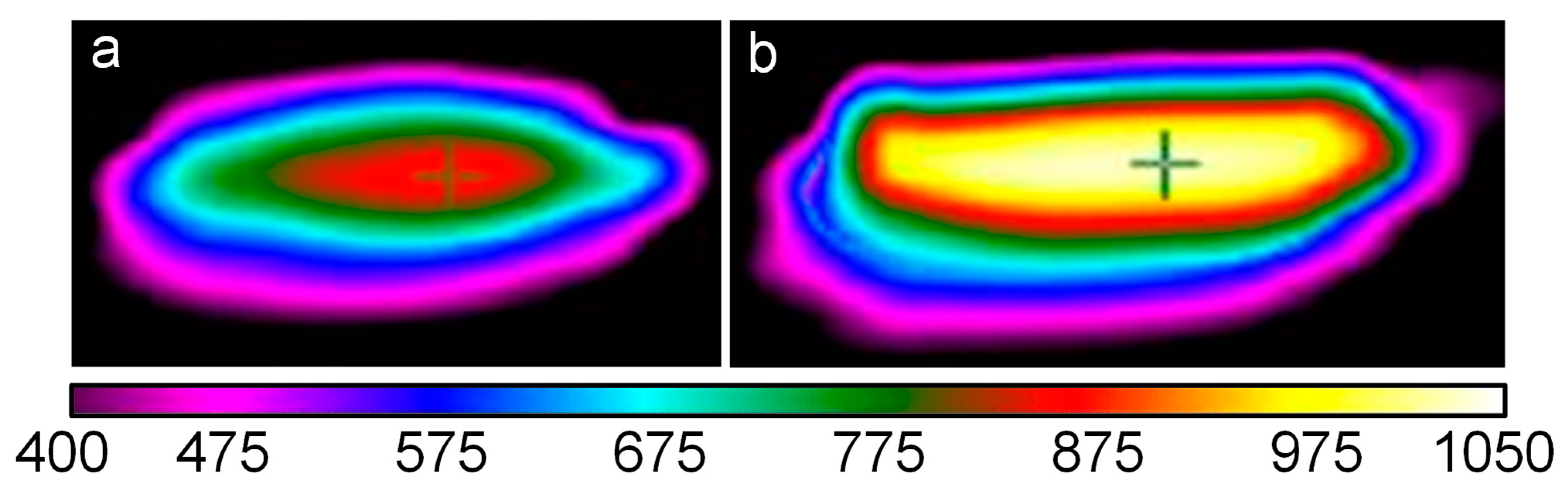
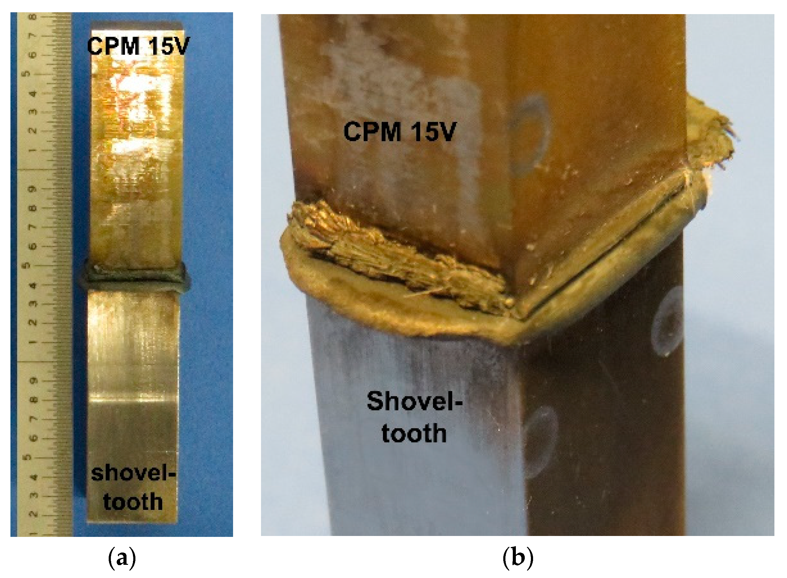
3.1. Thermal Conditions and Macroscopic Inspection

The temperature readings that were taken with the thermal camera during LFW of the CPM 15V tool steel to the shovel-tooth steel were analyzed for the two conditions (LF and HF) so as to extract temperature distribution maps. Figure 5 shows the surface temperature distribution map for the LF and HF conditions at a welding time when the maximum temperatures occurred, roughly just before the beginning of the forging stage. As a point of reference, it is noteworthy that the LFW process can be divided into four distinct phases: (1) the initial or contact phase, (2) transition or conditioning phase, (3) equilibrium or burn-off phase, and (4) deceleration or forge phase, which are described in detail in [6,8].
Examining the core area in the temperature distribution maps given in Figure 5, the location of the cross “†” represents the mid-width of the joint interface. In the LF condition, the maximum surface temperature in the core area did not exceed values above ~890 °C, and the temperature distribution area was relatively narrow, both along and across the interface. By contrast, for the HF condition, the maximum temperature at the interface surface was about 1000 °C, and the temperature distribution—both along and across the interface—was more uniform and broader relative to the LF condition. Surrounding these core areas of maximum temperatures, lower temperature isotherms were also apparent for both the LF and HF conditions, as represented by the different colors: red (~870 °C), cyan blue (~670 °C), royal blue (~600 °C), and purple (~500 °C), respectively.
As LFW is a solid-state joining technology, the maximum temperatures reached during processing were lower than the melting point of the materials. The LFW process is also self-regulated by the change in the material properties—that takes place in the materials as friction heating occurs—and the four phases of the weld cycle that must be present to achieve bonding at the interface using an appropriate selection of pre-set parameters/conditions [39]. During LFW of the CPM 15V tool steel to the shovel-tooth steel, the applied LF and HF conditions resulted in temperatures at the joint surface that exceeded the tempering conditions for both materials. This, in turn, led to localized softening of both materials, but considering the strength/hardness differences of the two materials, preferential plasticization and extrusion of the shovel-tooth steel occurred relative to CPM 15V steel, as illustrated in Figure 6 for the HF linear friction weld. This finding is consistent with preferential extrusion reported previously for other dissimilar material combinations [25,26,27,28] bonded by the LFW process.

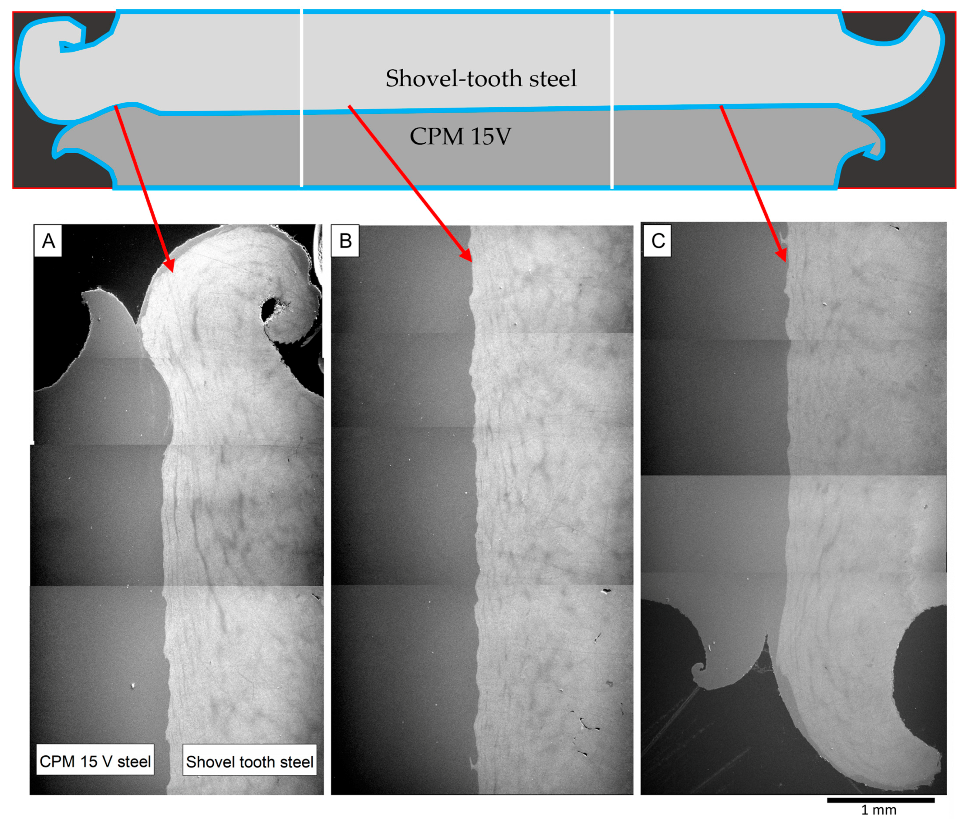
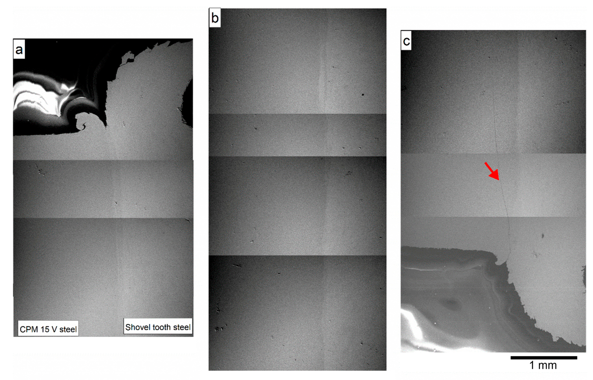
3.2. Microscopic Examination
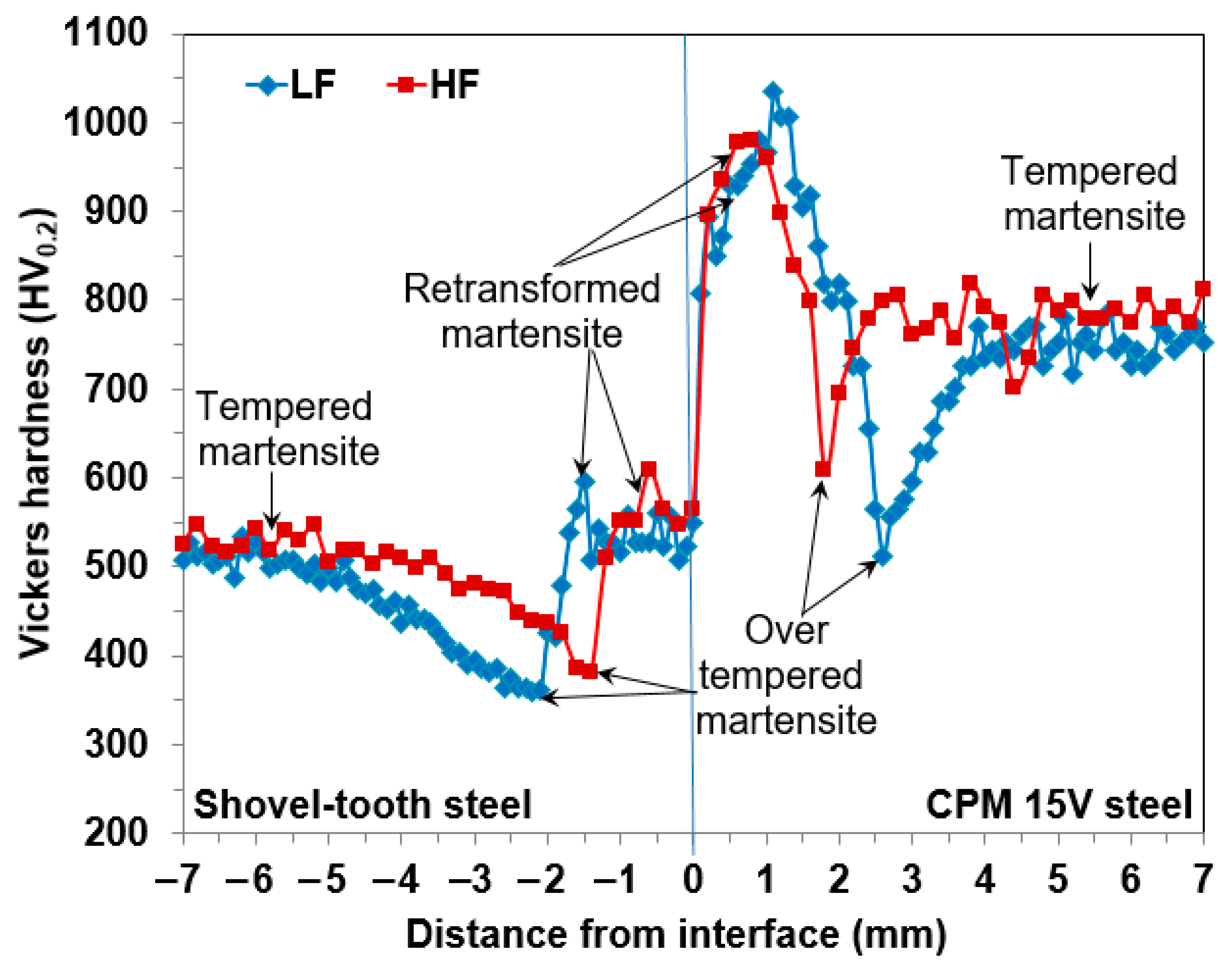
Microscopic evaluation of the welds between the CPM 15V and shovel-tooth steel materials was undertaken on Plane A (as defined in Figure 3), and the characteristics of the joint interface were examined using SEM. At low magnification, the wavy boundary or weld interface between the CPM 15V and shovel-tooth steel materials was clearly evident, as illustrated in Figure 7 for the HF weld condition. This continuous and wavy joint interface that formed between the CPM 15V and shovel-tooth steels appeared well-bonded without any noticeable defects, such as cracks, pores/voids, or delamination. The asymmetry of the flash layers at the edges of the joint was also apparent and points to the disparate extrusion of the plastically deformed material from the shovel-tooth and CPM 15V steels during LFW. It is worth mentioning that the micropores noticeable in Figure 7B, roughly 1 mm from the joint interface in the shovel-tooth steel microstructure, are defects that already existed in the alloyed carbon steel casting, likely generated during the casting process and not related to the welding process itself.
A similar examination conducted using SEM on the LF weld, as shown in Figure 8, presented comparable findings of a continuous joint interface (though less wavy) between the CPM 15V and the shovel-tooth steels without any noticeable defects, except for a single crack originating at one edge from the CPM 15V flash surface (Figure 8c) and extending inwards into the CPM 15V tool steel. Under the LF condition, the plastically deformed flash layers, mainly from the shovel-tooth steel, also exhibited surface ripples or ridges that indicate a stepwise extrusion from the oscillatory motion during the LFW process. The absence of these ripples/ridges on the plastically deformed flash layers of the HF weld intimate more uniform extrusion conditions, which may be related to the higher maximum temperatures relative to that experienced by the LF joint. It is well known that with increasing temperature, the flow stress of steels decreases; for instance, Elwazri et al. [40] studied the high temperature compressive behavior of hypo- and hyper-eutectoid carbon steels and reported a decrease in the flow stress by about 46% when the deformation temperature increased from 900 °C to 1000 °C. Similar trends have been observed in other alloy systems such as Fe-Mn-Al-C [41] and Fe-Mn-Si [42] steels under hot compression conditions. Thus, the lower temperatures (and thus higher flow stress) of the shovel-tooth steel during LFW under the LF condition hindered plastic deformation and flash expulsion, which in turn rendered a high potential for cracking that was exacerbated by the temperature gradients across the interface and the inherent brittleness of the CPM 15V material. It is interesting to note here that the crack in the LF weld circumvented the joint interface and propagated through the CPM 15V in a direction parallel to and at a distance of up to 400 µm from the interface. This region can be related to the heat affected zone (HAZ) on the CPM 15V side where the thermal gradients during LFW result in the formation of retransformed (untempered) martensite, as will be discussed next on the basis of high-resolution microscopy, as well as the hardness evolution across the joint interface.
Imaging at higher magnifications permitted the resolving of the metallurgical transformations occurring in the plastically affected zone (PAZ) and/or HAZ on either side of the joint interface between the CPM 15V and shovel-tooth steels, which are illustrated in Figure 9 for the HF weld. Microstructures in the LF weld had similar characteristics. Apart from the joint interface/boundary that appeared to be intimately bonded metallurgically, in the PAZ/HAZ, certain intermixed regions (Figure 10) confined close to the interface were present. Elemental mapping in these regions at the interface, using EDS, revealed a stark contrast of the main compositional elements—Fe, Cr, and V—at the weld line (Figure 11), which is indicative of the absence of long-range diffusion across the initial interface between the CPM 15V and shovel-tooth steels, at least at this micro-scale level investigated. This may be attributed to the limited atomic diffusion and element partitioning possible during LFW due to the very short durations at the elevated temperatures. Nonetheless, under the thermal conditions experienced by the LF and HF welds, two main transformations occurred: (1) dissolution/fragmentation of the spherical VC, and (2) formation of retransformed (untempered) martensite. Specifically, on the CPM 15V tool steel side, VC dissolution/fragmentation was noticeable, as indicated by the presence of non-uniformly sized smaller particles or their complete absence, especially in the intermixed regions close to the joint interface, as shown in Figure 10a. It is noteworthy that complete dissolution of VC in low carbon steels (in the face-centered cubic (f.c.c) state) can take place at temperatures as low as ~900 °C [43,44]. Hence, taking into account the temperature range achieved during LF and HF conditions, it is reasonable to assume that partial dissolution of VC took place. Additionally, fragmentation of VC is another feasible mechanism to explain the observed VC breakdown in the intermixed region—mainly due to the high strain rates and pressures during LFW that induce enormous shear and normal forces onto the VC particles and lead to their fragmentation. On the other hand, as illustrated in Figure 10b, the intermixed regions also consisted of pockets of retransformed martensite—i.e., the tempered martensite in the microstructure of the shovel-tooth steel and the CPM 15V matrix that transformed to austenite upon heating during LFW and then reverted back to martensite (untempered) upon cooling after welding. This formation of retransformed martensite was also observed in the PAZ/HAZ on both sides of the joint interface. To this end, close examination of the crack in the HAZ of the LF weld (Figure 12) revealed that the preferred propagation path was through the CPM 15V matrix, consisting most likely of retransformed martensite (considering the hardness as discussed in the next section). Additionally, evident from Figure 12 is the change in the propagation path of the crack when in the proximity of the VC particles, which also clearly points to a fracture occurring through the CPM 15V matrix.

3.3. Microhardness

A representative Vickers microhardness profile across the LF and HF joint interfaces (distance = 0 mm), in the dissimilar material welds between the CPM 15V tool steel and the shovel-tooth steel, is shown in Figure 13. The hardness of the tempered martensite microstructure on the shovel-tooth steel side remained nearly constant at ~500 HV0.2 up to roughly −5.0 mm from joint interface, at which point gradual softening commenced, more rapidly for the LF weld relative to the HF weld. This softening can be attributed to over-tempering of the martensitic microstructure, and hardness minima of ~380 HV0.2 and ~360 HV0.2 were respectively measured for the HF and LF conditions at distances of −1.4 mm and −2.2 mm, respectively, from the joint interface. From these minimum hardness values, a sharp rise in the hardness to ~600 HV0.2 was observed for both the LF and HF conditions. This may be attributed to the formation of retransformed martensite in the microstructure of the PAZ just adjacent to the joint interface on the shovel-tooth side. Specifically, the high frictional/thermal heat generated on heating during LFW transformed the martensite to austenite in the PAZ of the shovel-tooth steel and, upon rapid cooling after LFW, the austenite reverted to (retransformed) martensite. As this retransformed martensite was untempered, its hardness was higher than that of the tempered martensite microstructure of the shovel-tooth steel base material. The average hardness in the PAZ was about 550 HV0.2 for both the LF and HF welds, and this region remained nearly constant up to the joint interface at 0 mm, which delimited the end of the microstructural changes on the shovel-tooth steel side.
On the CPM 15V tool steel side, there was a similar trend in the microhardness evolution as a function of distance from the joint interface. From 0 mm to ~1 mm, there was a sharp increase in the hardness to a peak value of ~980 HV0.2 and ~1030 HV0.2 in the HAZ on the CPM 15V steel side of the HF and LF welds, respectively. This region of maximum hardness in the LF and HF welds can be related again to the formation of retransformed martensite in the matrix microstructure of the CPM 15V tool steel due to the high local thermal gradients, as described above for the PAZ on the shovel-tooth steel side. Then, the hardness decreased sharply to minimum values of ~610 HV0.2 and ~510 HV0.2 that were located at respective distances of ~1.8 mm and ~2.6 mm from the joint interface in the HF and LF welds, respectively. This region of minimum hardness in both the HF and LF welds is likely related to the over-tempered condition of the tempered martensite microstructure of the CPM 15V tool steel base material. From these minima on the CPM 15V steel side, the hardness increased gradually in both the LF and HF welds (though more rapidly in the latter) to a value of ~780 HV0.2, which corresponds to hardness of the tempered martensite microstructure in the unaffected CPM 15V base material.
From the hardness profiles across the joint interface between the CPM 15V and shovel-tooth steels, the width of the PAZ and/or HAZ could be measured to understand the extent of heat transfer in the LF and HF welds. The width of the PAZ/HAZ was delimited, for both the LF and HF conditions, by the initial hardness values of the unaffected base materials—tempered CPM 15V tool steel (780 HV0.2) and tempered shovel-tooth steel (500 HV0.2). Thus, for the LF condition, changes in hardness on the shovel-tooth steel side were seen to start at −5.0 mm and endured until 4.0 mm on the CPM 15V steel side, giving a width of 9.0 mm for PAZ/HAZ. By contrast, for the HF condition, the width of the PAZ was narrower, starting at −3.6 mm on the shovel-tooth side and continuing until 2.4 mm on the CPM 15V tool steel side, with a total width of 6.0 mm. This effect of higher frequency on reducing the size of the thermo-mechanically affected region has been reported for LFW of other materials, such as titanium alloy Ti-6Al-4V [5] and nickel-base superalloy (Waspaloy [20]) and linked to the material extrusion characteristics during LFW. In this work, LFW using HF was seen to improve material yielding and preferential extruding of the shovel-tooth steel, which in turn confined the size of the PAZ/HAZ closer to the joint interface and gave a width reduction of about 33% relative to LF condition. It is interesting to note that the peak-to-valley hardness difference was also about 12% lower for the HF condition (597 HV0.2) relative to the LF condition (675 HV0.2), and as hardness gradients can lead to strain localization along the joint interface, the use of LF during LFW predisposes the dissimilar material weld to a higher sensitivity to cracking relative to the HF setting.

3.4. Tensile Properties

The average room temperature tensile properties of the dissimilar material joints between the CPM 15V and shovel-tooth steels are listed in Table 3 for the LF and HF conditions. It is worth mentioning that the elastic modulus for each condition was determined from the stress–strain data by determining the slope of the initial linear elastic deformation region. The strength, ductility, and elastic modulus were the lowest for the LF weld with values of 138.0 MPa for the UTS, 0.1% for the EL, and 155.4 GPa for the E, respectively. By contrast, the UTS of the HF weld (552.9 MPa) was four times greater, and the modulus (227.6 GPa) was about 32% higher than the LF weld. For the HF condition, the joint efficiency—defined here as the ratio of the strength of the weld to the strength of the unaffected shovel-tooth steel base material—was calculated to be about 35%. However, the elastic modulus of the HF weld was statistically comparable to the shovel-tooth base material and that of the CPM 15V tool steel [45]. Considering the challenges faced for assembly of these dissimilar steels, these tensile properties obtained for the HF condition are a promising breakthrough for the LFW process, as typically this weld combination is unweldable by conventional technologies and tends to separate without applying any force due to the inherent disparate properties of the CPM 15V and shovel-tooth steels.
To gain further insight on the deformation response of the LF and HF welds, DIC techniques were applied during static tensile loading to understand the strain response and distribution, as presented in Figure 14. For the LF weld, the map of the strain distribution just before fracture showed strain localization around the joint and early fracture initiated from this region of maximum strain (of locally 0.14%) at the interface between the CPM 15V and shovel-tooth steels (Figure 14a). As the resistance to the loading/deformation of the LF weld was insufficient, the other regions of the gage length—comprising the CPM 15V and shovel-tooth steels—showed comparatively smaller strains (0.02–0.05). By contrast, the strain distribution in the HF weld was more even within the gage region of the tensile specimen (Figure 14b). Locally, the strains were higher on the shovel-tooth steel side (~0.3%) relative to the CPM 15V tool steel side (~0.18), which is explicable on the basis of their disparate properties (e.g., hardness and stiffness). Additionally, in the absence of strain localization in the vicinity of the joint, final fracture occurred in the HF weld at comparatively higher loads/stresses (four times greater than the LF condition), albeit still at the interface. Nonetheless, this relatively good resistance to loading/deformation determined in the present work for the HF weld provides the context necessary for future research aimed at optimizing process design for dissimilar joints between the CPM 15V and shovel-tooth steels.

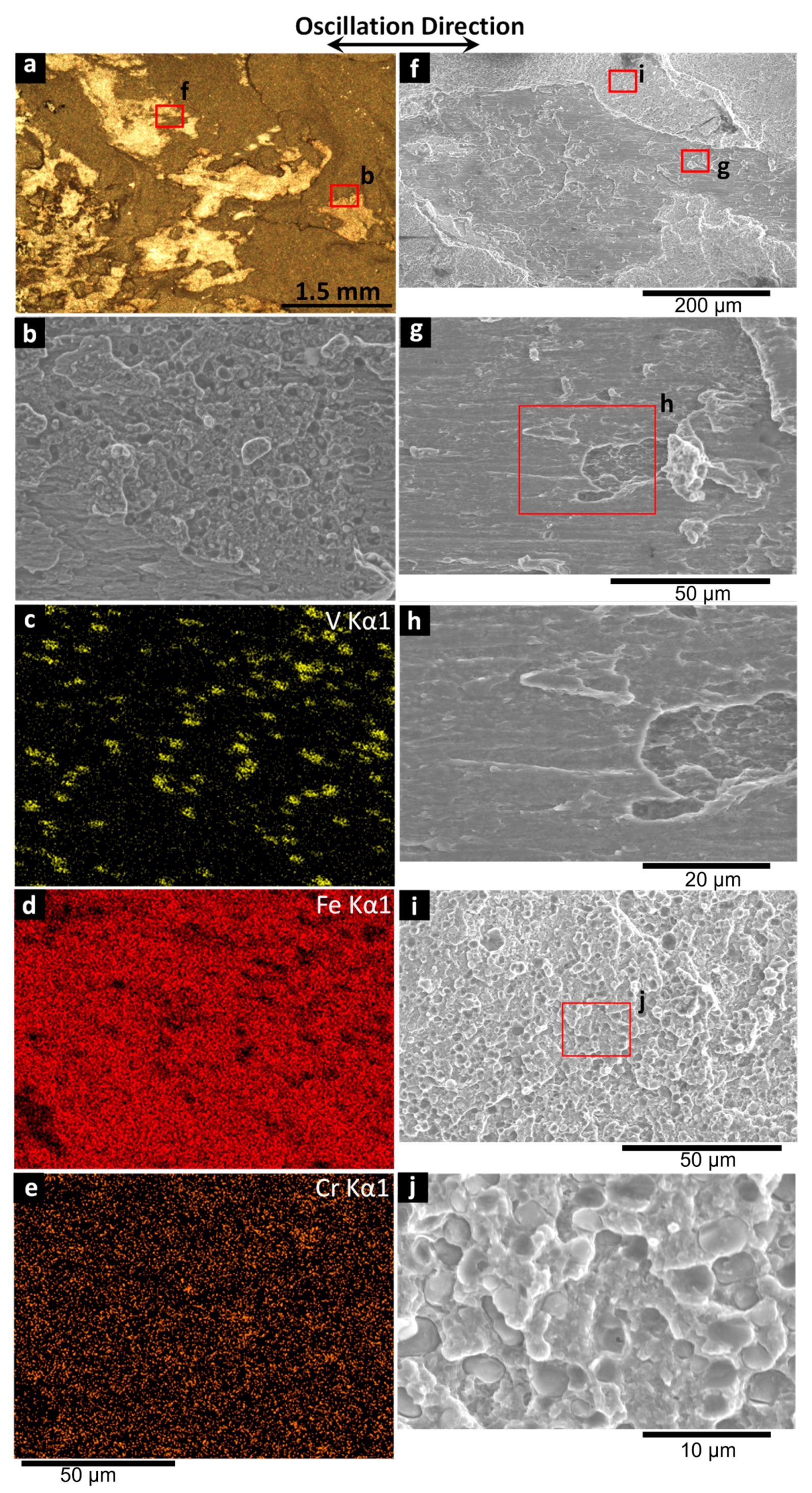
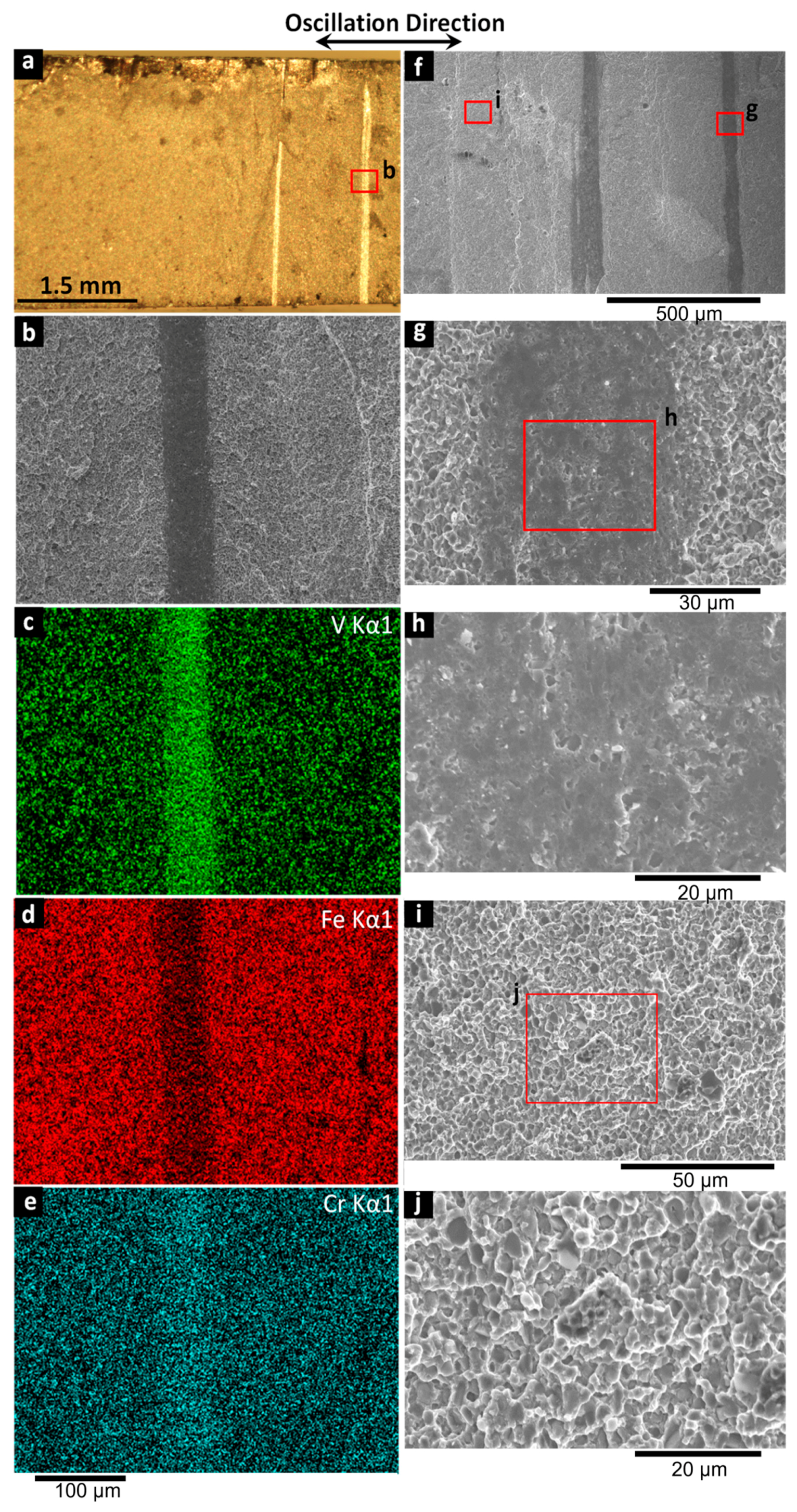
3.5. Fracture Surfaces

After tensile testing, the fracture surfaces of the LF and HF welds were examined using stereomicroscopy, SEM, and EDS, as shown in Figure 15 and Figure 16, respectively. Under stereomicroscopy, several regions with two main characteristics were visible: matte areas and reflective or shiny regions. On the fracture surface of the LF weld, the relative fraction of reflective areas (Figure 15a) was greater than that on the HF weld (Figure 16a). As well, the morphology of the reflective regions on the fracture surfaces were different between the LF weld fracture (irregular) and that of the HF weld (vertical bands perpendicular to the oscillation direction). Typically, the appearance of shiny/ reflective fracture surfaces are indicators of very little plastic deformation and brittle fracture mechanisms.
Examination of these areas using SEM with EDS elemental mapping on the fracture surfaces of the LF (Figure 15b–e) and HF (Figure 16b–e) welds gave different findings. Specifically, vanadium was observed to be evenly distributed over the entire fracture surface of the LF weld (Figure 15c), which suggests exposure of the CPM 15V surface and is understandable considering the poor bonding between the CPM 15V and shovel-tooth steels that was seen to result in cracking through the HAZ of the CPM 15V steel (Figure 8). By contrast, for the HF weld, only the narrow and dark vertical bands on the fractured surfaces were rich in vanadium and chromium, which points to a mixed fracture path, both through the shovel-tooth steel (where intermixing/bonding with the CPM 15V led to a higher load resistance of the joint) and CPM 15V steel (in regions that were not sufficiently bonded). High resolution images of the reflective and matte regions on the fracture surfaces of the LF and HF welds are shown, respectively, in Figure 15f–j and Figure 16f–j. The reflective areas, i.e., darker regions and/or vertical lines in SEM images of the LF and HF welds, respectively, exhibited features that were neither brittle nor ductile (Figure 15g,h and Figure 16g,h) but more similar to those apparent under sliding/abrasion conditions where surfaces are rubbed without forming a bond. In the matte area, dimpled ruptures accelerated by second phase particles (e.g., VC) were identified on the fracture surfaces of both the LF (Figure 15i,j) and HF (Figure 16i,j) welds, though the ruptured area with dimples was smaller in the former relative to the latter.

4. Conclusions

This research explored the feasibility of joining dissimilar materials, namely, CPM 15V tool steel and a low-carbon alloyed steel (extracted from a shovel-tooth), using linear friction welding (LFW) for wear applications. The results support the following conclusions:
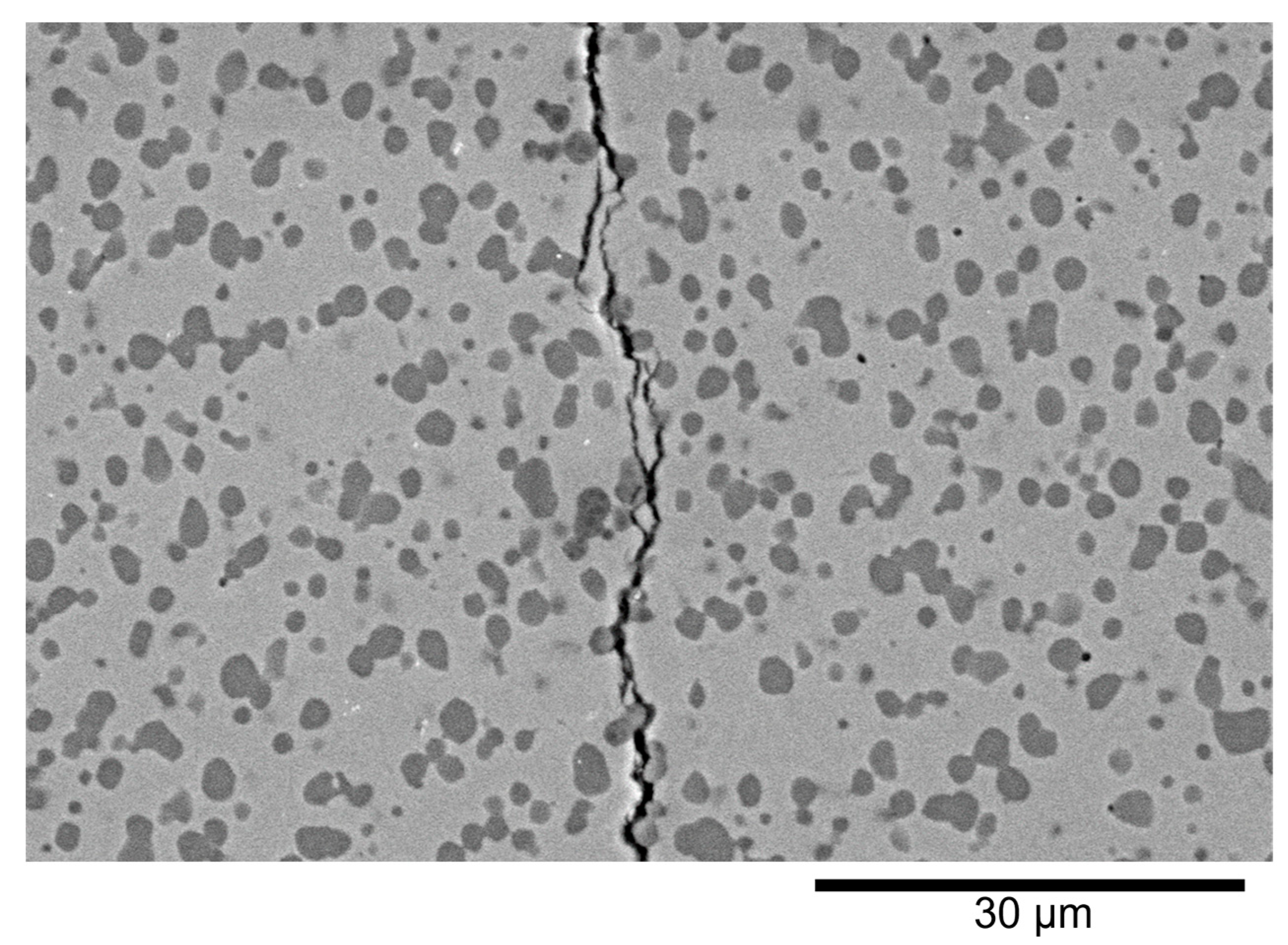
  • Two conditions of interest were examined for LFW of the CPM 15V tool steel to the shovel-tooth steel, namely, low frequency (LF) and high frequency (HF). Both conditions resulted in a continuous joint interface that was intimately bonded without the presence of discontinuities, such as pores, voids, and/or cracks at the joint interface. However, the LF weld exhibited a crack that originated in the flash on the CPM 15V steel side and extended towards its heat-affected zone (HAZ); its occurrence was related to the lower maximum temperatures (and thus greater resistance to plastic deformation) achieved under the LF condition during LFW relative to the HF condition.
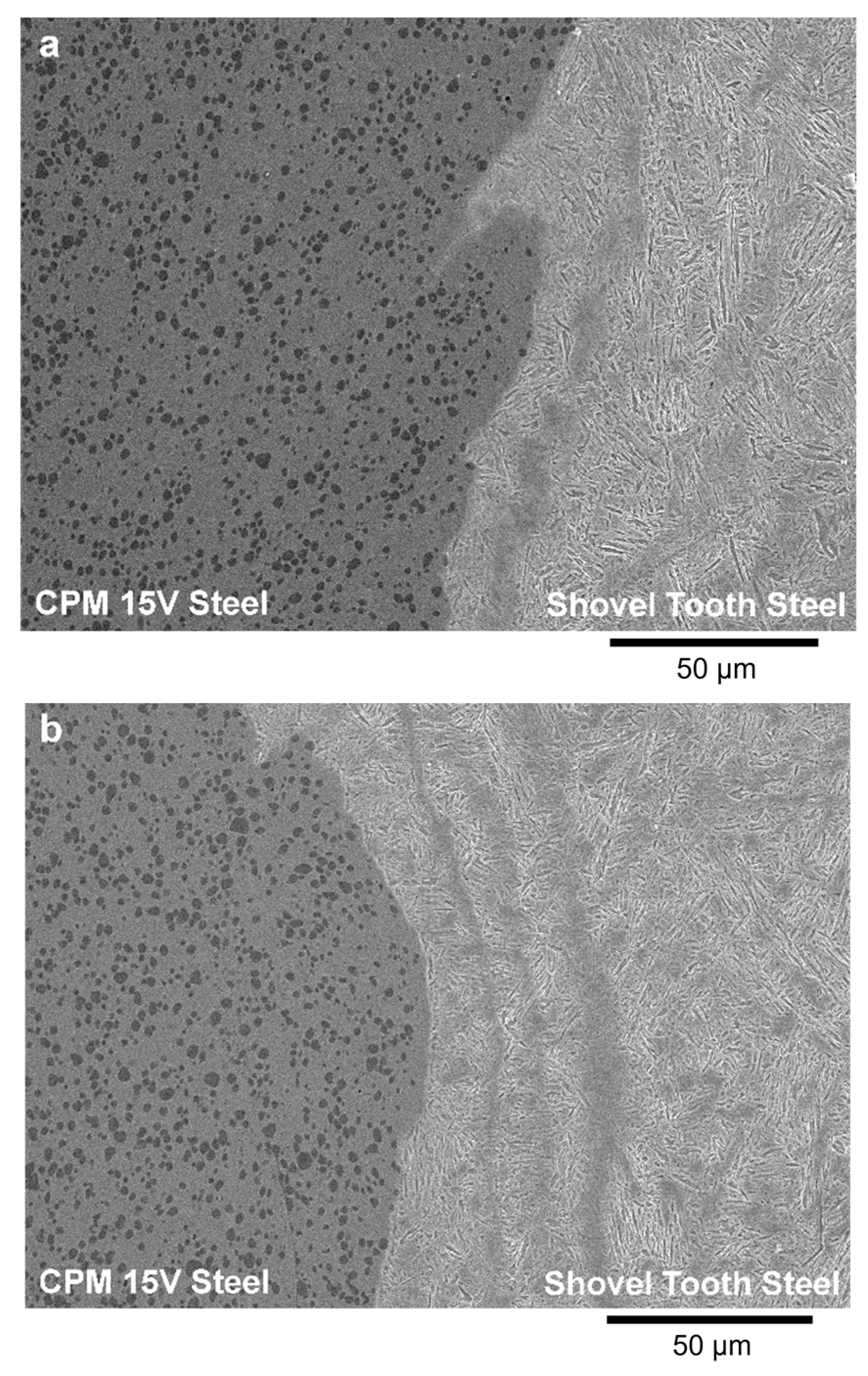
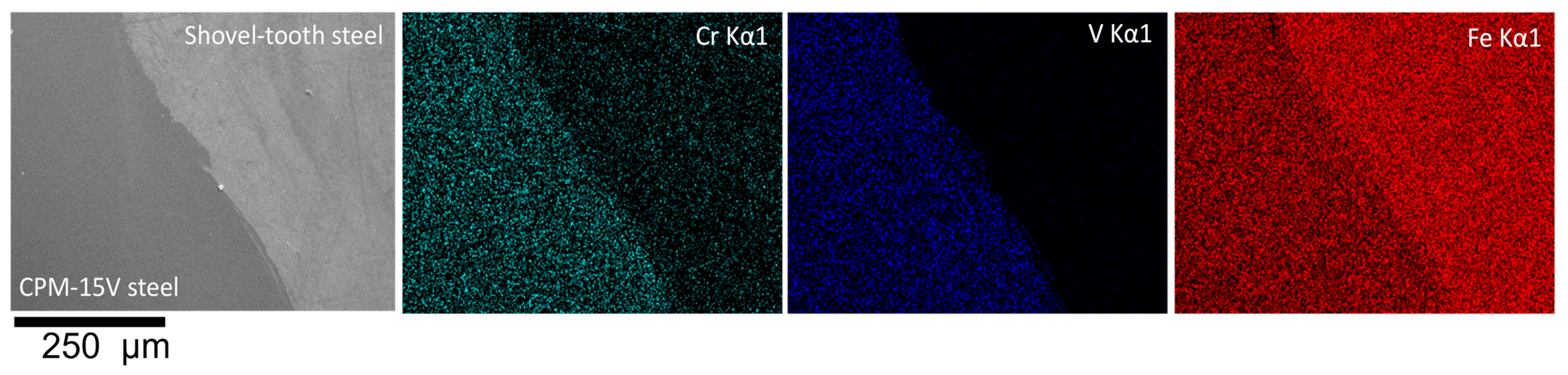
  • A distinct interface remained at the initial joint interface between the CPM 15V tool steel and the shovel-tooth steel, indicating that long-range ordering on diffusion during LFW was insignificant across the interface due to the short times at elevated temperatures that limited element diffusion (as verified using energy X-ray dispersive mapping) and partitioning.
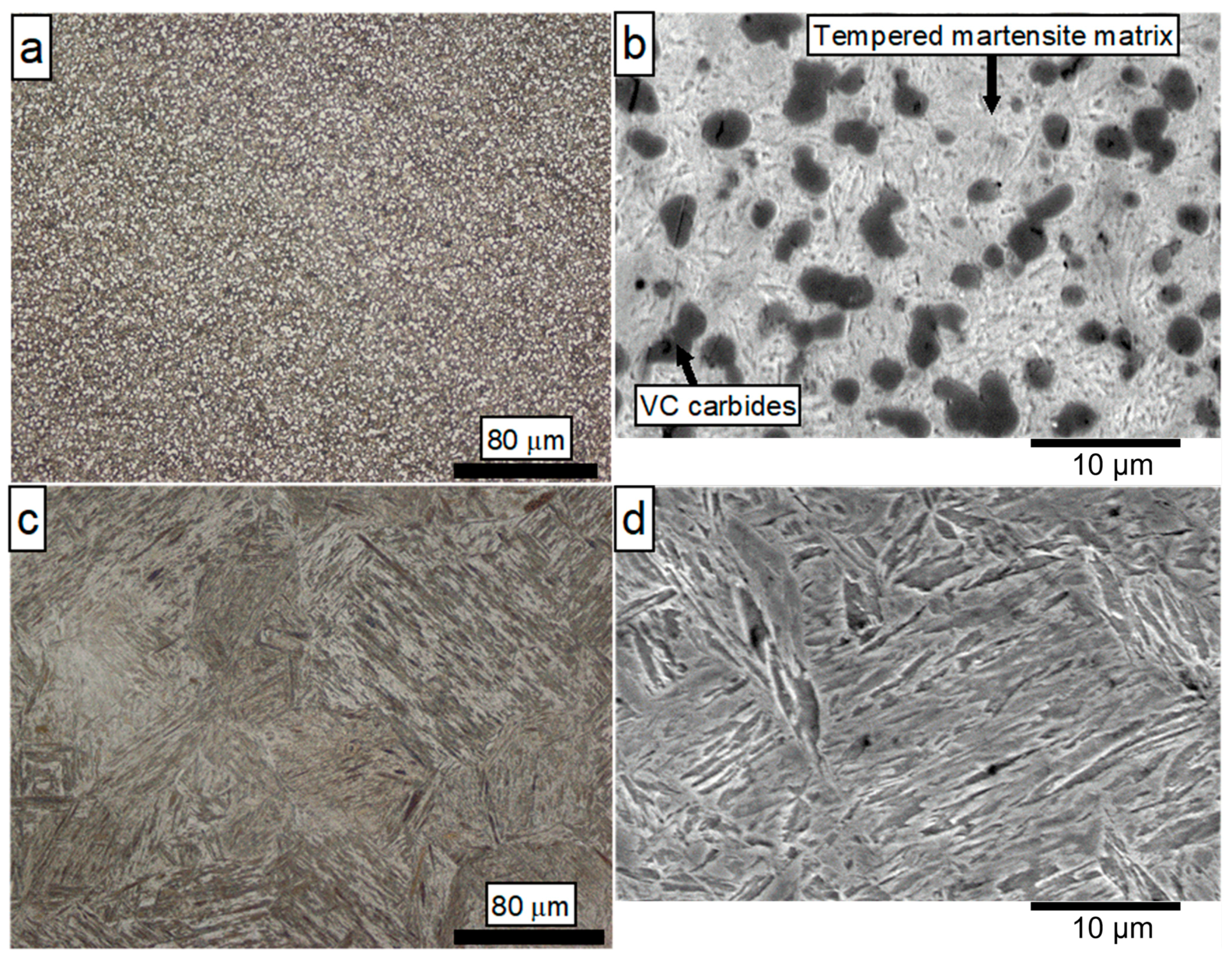
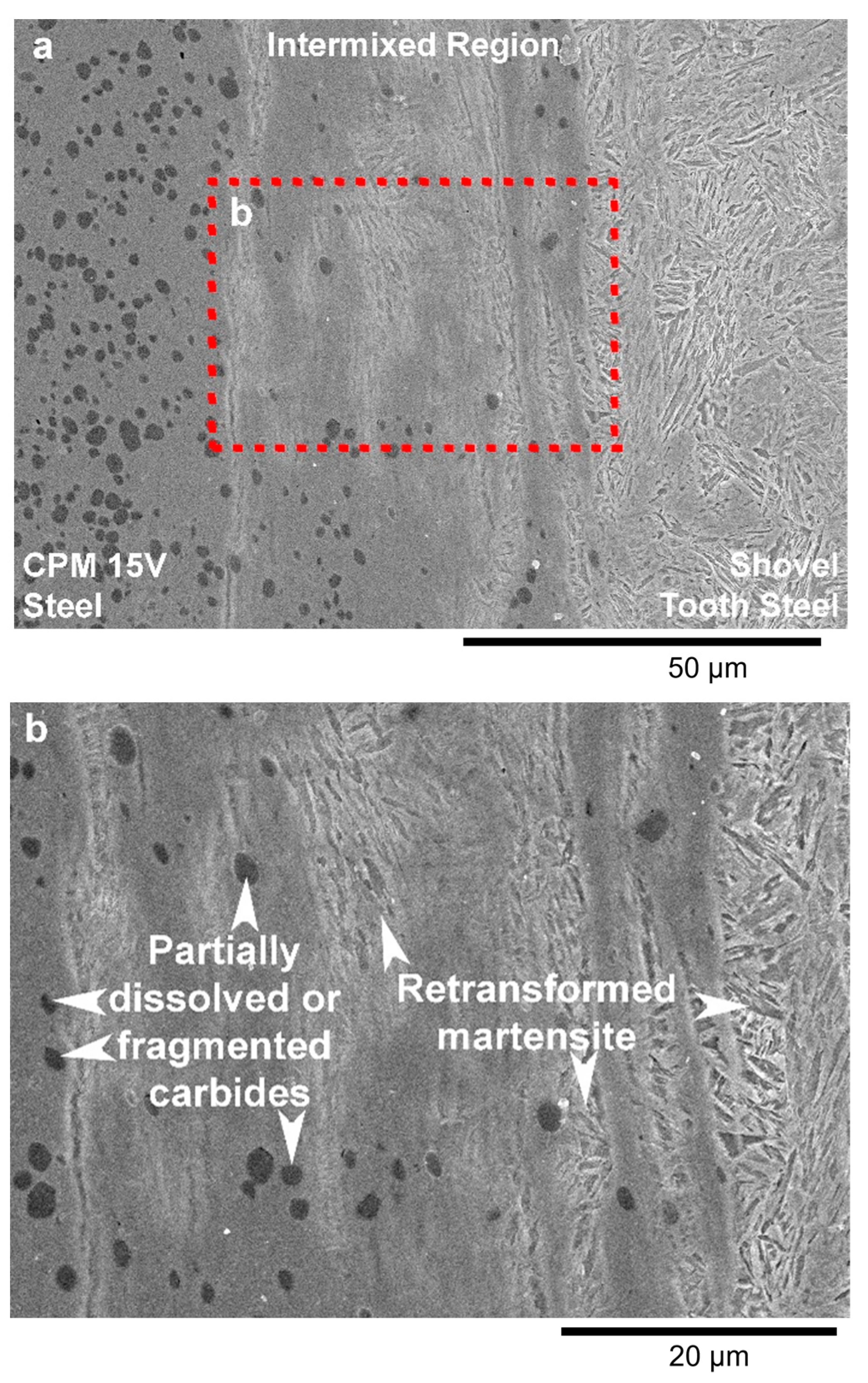
  • The thermal history during LFW resulted in two main transformations in the HAZ and/or plastically affected zone (PAZ) of the LF and HF welds: dissolution/fragmentation of vanadium carbides on the CPM 15V side, and formation of retransformed martensite on the shovel-tooth side as well as in the matrix on the CPM 15V tool steel side. These transformations affected the hardness in PAZ/HAZ, with softening and hardening occurring on both sides of the joint interface due to over-tempering of the tempered martensite microstructure of the base materials and formation of retransformed (untempered) martensite, respectively.
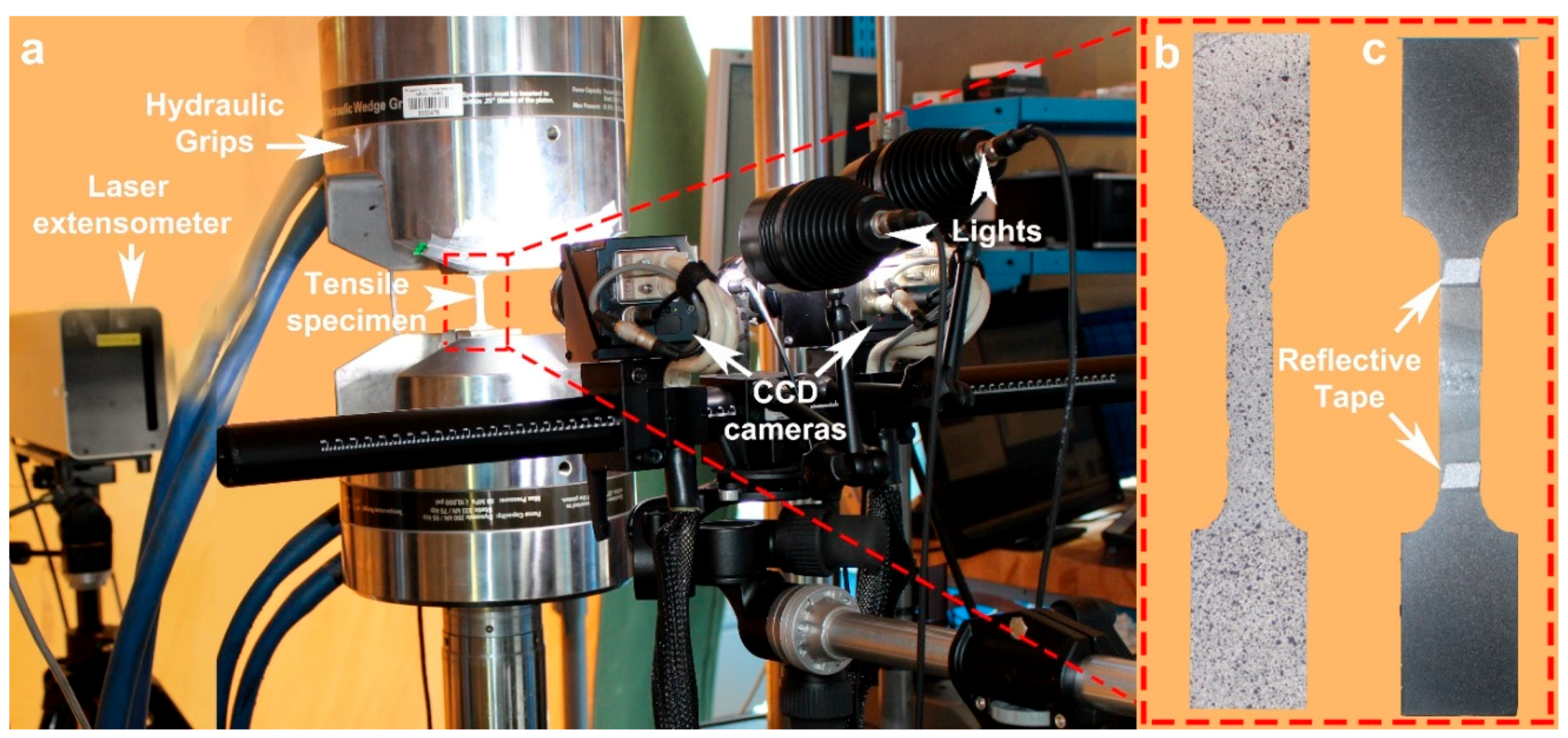
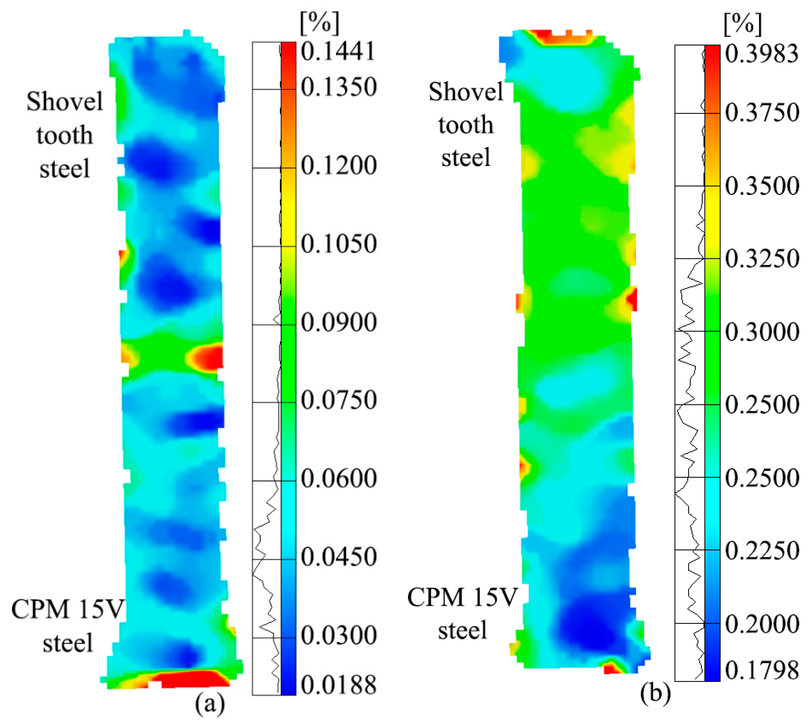
  • The tensile strength and ductility of the dissimilar material joints were higher for the HF condition relative to the LF condition. Strain mapping using digital image correlation during tensile loading revealed rapid strain localization around the joint interface for the LF weld, whereas the strain distribution was relatively even in the HF weld.
  • The fractured surfaces of the HF weld showed a higher fraction of matte areas exhibiting dimple rupture features relative to the LF weld that consisted of shinier (reflective) areas, which were related to brittle areas.
  • Manufacturing of joints between dissimilar materials, namely, CPM 15V tool steel and a shovel-tooth steel, using LFW was shown to be feasible, and the properties are amenable for wear applications.

Author Contributions

Conceptualization, P.W., O.A.Z. and J.J.; methodology, P.W., O.A.Z., J.J. and J.G.; software, P.W. and J.G.; validation, J.J. and J.G.; formal analysis, O.A.Z. and P.W.; investigation, P.W. and O.A.Z.; resources, J.J. and J.G.; data curation, O.A.Z. and P.W.; writing—original draft preparation, O.A.Z. and P.W.; writing—review and editing, P.W., O.A.Z., J.J. and J.G.; visualization, P.W. and O.A.Z.; supervision, P.W., J.J. and J.G.; project administration, J.J. and J.G.; funding acquisition, J.J. and J.G. All authors have read and agreed to the published version of the manuscript.

Funding

This research was funded by the High Efficiency Mining (HEM) program of the National Research Council Canada under project A1-019801 entitled “Development of Linear Friction Welding Technologies for Joining Dissimilar Materials for Mining Wear Applications”.

Institutional Review Board Statement

Not applicable.

Informed Consent Statement

Not applicable.

Data Availability Statement

The authors confirm that the data supporting the findings of this study are available within the article.

Acknowledgments

The authors are grateful to Maxime Guérin for performing the linear friction welding experiments and Xavier Pelletier for assisting with the sample preparations.

Conflicts of Interest

The authors declare no conflict of interest. The funders had no role in the design of the study; in the collection, analyses, or interpretation of data; in the writing of the manuscript; or in the decision to publish the results.

References

  1. Zambrano, O.A. A Review on the Effect of Impact Toughness and Fracture Toughness on Impact-Abrasion Wear. J. Mater. Eng. Perform. 2021, 30, 7101–7116. [Google Scholar]
  2. Maalekian, M. Friction welding–Critical assessment of literature. Sci. Technol. Weld. Join. 2007, 12, 738–759. [Google Scholar]
  3. Salamati, M.; Soltanpour, M.; Fazli, A. Processing and tooling considerations in joining by forming technologies; part B—Friction-based welding. Int. J. Adv. Manuf. Technol. 2020, 106, 4023–4081. [Google Scholar]
  4. Li, W.; Vairis, A.; Preuss, M.; Ma, T. Linear and rotary friction welding review. Int. Mater. Rev. 2016, 61, 71–100. [Google Scholar]
  5. Vairis, A.; Frost, M. High frequency linear friction welding of a titanium alloy. Wear 1998, 217, 117–131. [Google Scholar] [CrossRef]
  6. Wanjara, P.; Jahazi, M. Linear friction welding of Ti-6Al-4V: Processing, microstructure, and mechanical-property inter-relationships. Metall. Mater. Trans. A 2005, 36, 2149–2164. [Google Scholar]
  7. Dalgaard, E.; Wanjara, P.; Gholipour, J.; Jonas, J.J. Evolution of microstructure, microtexture and mechanical properties of linear friction welded IMI 834. Can. Metall. Q. 2012, 51, 269–276. [Google Scholar] [CrossRef]
  8. Dalgaard, E.; Wanjara, P.; Gholipour, J.; Cao, X.; Jonas, J. Linear friction welding of a near-β titanium alloy. Acta Mater. 2012, 60, 770–780. [Google Scholar] [CrossRef]
  9. Dalgaard, E.; Wanjara, P.; Gholipour, J.; Jonas, J.J. Linear Friction Welding of a Forged Near-α Titanium Alloy. Mater. Sci. Forum 2012, 706–709, 211–216. [Google Scholar]
  10. Wanjara, P.; Dalgaard, E.; Gholipour, J.; Cao, X.; Cuddy, J.; Jonas, J.J. Effect of Pre- and Post-weld Heat Treatments on Linear Friction Welded Ti-5553. Metall. Mater. Trans. A 2014, 45, 5138–5157. [Google Scholar]
  11. Stinville, J.C.; Bridier, F.; Ponsen, D.; Wanjara, P.; Bocher, P. High and low cycle fatigue behavior of linear friction welded Ti–6Al–4V. Int. J. Fatigue 2015, 70, 278–288. [Google Scholar] [CrossRef]
  12. Su, Y.; Li, W.; Wang, X.; Ma, T.; Yang, X.; Vairis, A. On microstructure and property differences in a linear friction welded near-alpha titanium alloy joint. J. Manuf. Process. 2018, 36, 255–263. [Google Scholar] [CrossRef]
  13. Rajan, S.; Wanjara, P.; Gholipour, J.; Kabir, A.S. Microstructure, Tensile Properties, and Fatigue Behavior of Linear Friction-Welded Ti-6Al-2Sn-4Zr-2Mo-0.1Si. Materials 2020, 14, 30. [Google Scholar] [CrossRef]
  14. Karadge, M.; Preuss, M.; Withers, P.; Bray, S. Importance of crystal orientation in linear friction joining of single crystal to polycrystalline nickel-based superalloys. Mater. Sci. Eng. A 2008, 491, 446–453. [Google Scholar] [CrossRef]
  15. Ola, O.T.; Ojo, O.A.; Wanjara, P.; Chaturvedi, M.C. Crack-Free Welding of IN 738 by Linear Friction Welding. Adv. Mater. Res. 2011, 278, 446–453. [Google Scholar] [CrossRef] [Green Version]
  16. Ola, O.T.; Ojo, O.A.; Wanjara, P.; Chaturvedi, M.C. Chaturvedi, Analysis of Microstructural Changes Induced by Linear Friction Welding in a Nickel-Base Superalloy. Metall. Mater. Trans. A 2011, 42, 3761. [Google Scholar] [CrossRef]
  17. Chamanfar, A.; Jahazi, M.; Gholipour, J.; Wanjara, P.; Yue, S. Mechanical Property and Microstructure of Linear Friction Welded WASPALOY. Metall. Mater. Trans. A 2011, 42, 729–744. [Google Scholar] [CrossRef]
  18. Chamanfar, A.; Jahazi, M.; Gholipour, J.; Wanjara, P.; Yue, S. Maximizing the integrity of linear friction welded Waspaloy. Mater. Sci. Eng. A 2012, 555, 117–130. [Google Scholar] [CrossRef]
  19. Ola, O.T.; Ojo, O.A.; Wanjara, P.; Chaturvedi, M.C. A Study of Linear Friction Weld Microstructure in Single Crystal CMSX-486 Superalloy. Metall. Mater. Trans. A 2012, 43, 921–933. [Google Scholar] [CrossRef]
  20. Wanjara, P.; Dalgaard, E.; Gholipour, J.; Larose, J. Linear Friction Welding of a Single Crystal Superalloy. Mater. Sci. Forum 2012, 706–709, 3022–3027. [Google Scholar] [CrossRef]
  21. Chamanfar, A.; Jahazi, M.; Gholipour, J.; Wanjara, P.; Yue, S. Suppressed liquation and microcracking in linear friction welded WASPALOY. Mater. Des. (1980–2015) 2012, 36, 113–122. [Google Scholar] [CrossRef]
  22. Chamanfar, A.; Jahazi, M.; Gholipour, J.; Wanjara, P.; Yue, S. Modeling Grain Size and Strain Rate in Linear Friction Welded Waspaloy. Metall. Mater. Trans. A 2013, 44, 4230–4238. [Google Scholar] [CrossRef] [Green Version]
  23. Vishwakarma, K.R.; Ojo, O.A.; Wanjara, P.; Chaturvedi, M.C. Chaturvedi, Microstructural Analysis of Linear Friction-Welded 718 Plus Superalloy. JOM 2014, 66, 2525–2534. [Google Scholar] [CrossRef]
  24. Chamanfar, A.; Jahazi, M.; Gholipour, J.; Wanjara, P.; Yue, S.; Yue, S. Analysis of integrity and microstructure of linear friction welded Waspaloy. Mater. Charact. 2015, 104, 149–161. [Google Scholar] [CrossRef]
  25. Chamanfar, A.; Jahazi, M.; Gholipour, J.; Wanjara, P.; Yue, S. Linear friction welding of Al–Cu: Part 1—Process evaluation. Can. Metall. Q. 2011, 50, 350–359. [Google Scholar]
  26. Wanjara, P.; Dalgaard, E.; Trigo, G.; Mandache, C.; Comeau, G.; Jonas, J.J. Linear friction welding of Al–Cu Part 2—Interfacial characteristics. Can. Metall. Q. 2011, 50, 360–370. [Google Scholar] [CrossRef]
  27. Wanjara, P.; Gholipour, J.; Watanabe, K.; Nezaki, K.; Tian, Y.; Brochu, M. Linear Friction Welding of IN718 to Ti6Al4V. Mater. Sci. Forum 2017, 879, 2072–2077. [Google Scholar] [CrossRef]
  28. Wanjara, P.; Naik, B.S.; Yang, Q.; Cao, X.; Gholipour, J.; Chen, D.L. Linear Friction Welding of Dissimilar Materials 316L Stainless Steel to Zircaloy-4. Metall. Mater. Trans. A 2018, 49, 1641–1652. [Google Scholar] [CrossRef]
  29. Rajan, S.; Wanjara, P.; Gholipour, J.; Kabir, A.S. Joining of Dissimilar Alloys Ti-6Al-4V and Ti-6Al-2Sn-4Zr-2Mo-0.1Si Using Linear Friction Welding. Materials 2020, 13, 3664. [Google Scholar] [CrossRef]
  30. Lee, W.-B.; Kim, Y.-J.; Jung, S.-B. Effects of copper insert layer on the properties of friction welded joints between TiAl and AISI 4140 structural steel. Intermetallics 2004, 12, 671–678. [Google Scholar] [CrossRef]
  31. Bhamji, I.; Preuss, M.; Threadgill, P.L.; Moat, R.J.; Addison, A.C.; Peel, M.J. Linear friction welding of AISI 316L stainless steel. Mater. Sci. Eng. A 2010, 528, 680–690. [Google Scholar] [CrossRef]
  32. Madhusudhan Reddy, G.; Venkata Ramana, P. Role of nickel as an interlayer in dissimilar metal friction welding of maraging steel to low alloy steel. J. Mater. Process. Technol. 2012, 212, 66–77. [Google Scholar] [CrossRef]
  33. Kumar, R.; Balasubramanian, M. Experimental investigation of Ti–6Al–4V titanium alloy and 304L stainless steel friction welded with copper interlayer. Def. Technol. 2015, 11, 65–75. [Google Scholar] [CrossRef] [Green Version]
  34. Kirik, I. Weldability of Ti6Al4V to AISI 2205 with a nickel interlayer using friction welding. Mater. Tehnol. 2016, 50, 353–356. [Google Scholar] [CrossRef]
  35. Mogami, H.; Matsuda, T.; Sano, T.; Yoshida, R.; Hori, H.; Hirose, A. High-frequency linear friction welding of aluminum alloys. Mater. Des. 2018, 139, 457–466. [Google Scholar] [CrossRef]
  36. Matsuda, T.; Adachi, H.; Sano, T.; Yoshida, R.; Hori, H.; Ono, S.; Hirose, A. High-frequency linear friction welding of aluminum alloys to stainless steel. J. Mater. Process. Technol. 2019, 269, 45–51. [Google Scholar] [CrossRef]
  37. ASTM International. E384-17 Standard Test Method for Microindentation Hardness of Materials; West Conshohocken: Montgomery County, PA, USA, 2017. [Google Scholar]
  38. ASTM International. E8/E8M-16ae1-Standard Test Methods for Tension Testing of Metallic Materials; West Conshohocken: Montgomery County, PA, USA, 2016. [Google Scholar]
  39. Vairis, A. Mathematical Modelling of the Linear Friction Welding Process. J. Eng. Sci. Technol. Rev. 2012, 5, 25–31. [Google Scholar] [CrossRef]
  40. Elwazri, A.M.; Wanjara, P.; Yue, S. Effect of Carbon Content on Dynamic Recrystallization Behaviour of Plain Carbon Steels. Can. Metall. Q. 2013, 43, 507–512. [Google Scholar] [CrossRef]
  41. Zambrano, O.A.; Valdés, J.; Aguilar, Y.; Coronado, J.J.; Rodríguez, S.A.; Logé, R.E. Hot deformation of a Fe-Mn-Al-C steel susceptible of κ-carbide precipitation. Mater. Sci. Eng. A 2017, 689, 269–285. [Google Scholar] [CrossRef]
  42. Zambrano, O.A.; Logé, R.E. Dynamic recrystallization study of a Fe-Mn-Si based shape memory alloy in constant and variable thermomechanical conditions. Mater. Charact. 2019, 152, 151–161. [Google Scholar] [CrossRef]
  43. Acevedo Reyes, D.; Perez, M.; Pecoraro, S.; Vincent, A.; Epicier, T.; Dierickx, P. Vanadium carbide dissolution during austenitisation of a model microalloyed fecv steel. In Materials Science Forum; Trans Tech Publications Ltd.: Stafa-Zurich, Switzerland, 2005. [Google Scholar]
  44. Baker, T.N. Processes, microstructure and properties of vanadium microalloyed steels. Mater. Sci. Technol. 2009, 25, 1083–1107. [Google Scholar] [CrossRef] [Green Version]
  45. CPM 15V Steel Properties. Available online: https://www.crucible.com/PDFs/%5CDataSheets2010%5Cds15Vv1%202010.pdf (accessed on 3 February 2023).
Figure 1. Photo and approximate dimensions of the tip portion of a shovel tooth used in Canadian oil sands mining.
Jmmp 07 00051 g001
Figure 2. Microstructures of the materials used for the welding study: (a,b) the CPM 15V steel, and (c,d) shovel-tooth using optical microscopy and SEM, respectively.
Jmmp 07 00051 g002
Figure 3. Schematic showing (a) the shovel-tooth steel and CPM 15V tool steel coupons, as well as their dimensions and configuration for LFW with a thermal camera; (b) the dissimilar material joint and extraction of transverse weld cross-section; (c) the extraction of tensile specimens from the weld; and (d) the subsize tensile specimen geometry that had a gage length of 25 mm, a width of 12 mm, and a thickness of 3 mm.
Jmmp 07 00051 g003
Figure 4. (a) The MTS tensile system set up with the laser extensometer and Aramis® DIC that shows the tensile specimen surface with (b) a painted speckled pattern on one side and (c) retro-reflective tape on the other side.
Jmmp 07 00051 g004
Figure 5. Thermal camera temperature maps at the joint interface of the CPM 15V tool steel to the shovel-tooth steel that were recorded at the onset of the forging stage where the maximum temperature occurred for the (a) LF and (b) HF conditions, respectively.
Jmmp 07 00051 g005
Figure 6. Front (a) and isometric (b) views of the linear friction weld between a shovel-tooth and CPM 15V tool steel (HF condition).
Jmmp 07 00051 g006
Figure 7. SEM micrographs taken along the entire interface (along Plane A in Figure 2) from (A) left, passing through (B) the middle, to (C) the right of the HF linear friction weld between dissimilar materials CPM 15V tool steel and a shovel-tooth steel.
Jmmp 07 00051 g007
Figure 8. SEM micrographs taken at the interface (along Plane A in Figure 2) from (a) left, passing through (b) the middle, to (c) the right of the LF weld, where the arrow demarcated in (c) highlights the crack that originated at the flash surface and extended into the CPM 15V tool steel.
Jmmp 07 00051 g008
Figure 9. Representative microstructures at the interface for the HF condition observed by SEM, where (a) and (b) are different regions at the interface.
Jmmp 07 00051 g009
Figure 10. Intermixing of microstructures in some limited regions observed by SEM at the interface for the HF condition, where (b) is an enlarged micrograph of (a).
Jmmp 07 00051 g010
Figure 11. SEM micrograph and EDS maps obtained at the interface for the HF condition.
Jmmp 07 00051 g011
Figure 12. Preferred crack propagation path that occurred through the matrix of the CPM 15V in the PAZ/HAZ of the LF weld.
Jmmp 07 00051 g012
Figure 13. Hardness profile of each welded condition as a function of distance.
Jmmp 07 00051 g013
Figure 14. Strain distributions immediately prior to fracture of the LF (a) and HF (b) welds under tensile loading.
Jmmp 07 00051 g014
Figure 15. Images of the fracture surface after tensile fracture of LF weld under (a) stereomicroscopy, (b) SEM, (ce) EDS mapping, and (fj) SEM.
Jmmp 07 00051 g015
Figure 16. Images of the fracture surface after tensile fracture of HF weld under (a) stereomicroscopy, (b) SEM, (ce) EDS mapping, and (fj) SEM.
Jmmp 07 00051 g016
Table 1. Chemical compositions (wt%) of the steels joined by LFW.
SteelCMnSiCrMoVSFe
Shovel-tooth0.2581.141.482.110.230.0050.008Balance
CPM 15V3.400.500.905.251.3014.500.07Balance
Table 2. LFW parameters used to join CPM 15V steel and the low-carbon steel.
IDFrequency (Hz)Friction Pressure (MPa)Burn-Off Pressure (MPa)Forge Pressure (MPa)Amplitude (mm)
High-frequency1004090902
Low-frequency204090902
Table 3. Average tensile properties of the LF and HF welds. The statistical significance is based on three repetitions per condition.
ConditionUTS (MPa)EL (%)E (GPa)
LF138.0 ± 32.70.1 ± 0.0155.4 ± 25.0
HF552.9 ± 29.20.2 ± 0.0227.6 ± 21.8
Shovel-tooth1583.6 ± 77.84.8 ± 2.4219.92 ± 33.8
CPM-15V [45]NANA235 GPa
NA = not available/applicable.
Disclaimer/Publisher’s Note: The statements, opinions and data contained in all publications are solely those of the individual author(s) and contributor(s) and not of MDPI and/or the editor(s). MDPI and/or the editor(s) disclaim responsibility for any injury to people or property resulting from any ideas, methods, instructions or products referred to in the content.

