Article

Crystallization and Aging Behavior of Polyetheretherketone PEEK within Rapid Tooling and Rubber Molding

1
Department of Mechanical Engineering, University of Applied Sciences Aachen, 52064 Aachen, Germany
2
Department of Manufacturing Engineering, Technical University of Cluj-Napoca, 400641 Cluj-Napoca, Romania
*
Author to whom correspondence should be addressed.
J. Manuf. Mater. Process. 2022, 6(5), 93; https://doi.org/10.3390/jmmp6050093
Submission received: 20 July 2022 / Revised: 23 August 2022 / Accepted: 24 August 2022 / Published: 26 August 2022
(This article belongs to the Special Issue Advances in Injection Molding: Process, Materials and Applications)

Abstract

:
In times of short product life cycles, additive manufacturing and rapid tooling are important methods to make tool development and manufacturing more efficient. High-performance polymers are the key to mold production for prototypes and small series. However, the high temperatures during vulcanization injection molding cause thermal aging and can impair service life. The extent to which the thermal stress over the entire process chain stresses the material and whether it leads to irreversible material aging is evaluated. To this end, a mold made of PEEK is fabricated using fused filament fabrication and examined for its potential application. The mold is heated to 200 °C, filled with rubber, and cured. A differential scanning calorimetry analysis of each process step illustrates the crystallization behavior and first indicates the material resistance. It shows distinct cold crystallization regions at a build chamber temperature of 90 °C. At an ambient temperature above Tg, crystallization of 30% is achieved, and cold crystallization no longer occurs. Additional tensile tests show a decrease in tensile strength after ten days of thermal aging. The steady decrease in recrystallization temperature indicates degradation of the additives. However, the tensile tests reveal steady embrittlement of the material due to increasing crosslinking.

1. Introduction

Polymer-based AM processes within rapid tooling of injection molds are increasingly favored by establishing new process controls and high-performance polymers (HPPs). Lastly, this trend is promoted by faster and easier AM plug-and-play systems on the market. This is due to the steady market growth and increasingly short product life cycles. This poses a challenge in mold development, creating a demand for cost-effective and rapid prototyping processes and shortened development times for injection molds. The aim here is to produce prototypes as quickly as possible and thus also to minimize the high cost of iterative mold development. Conventional tools are made of tool steels or aluminum alloys. However, the production of these is characterized by an increased expenditure of resources and time. Apart from that, flexibility in case of change requests is limited. If changes to the tool are required, they have to be elaborately modified or completely remanufactured using complex processes. For successful product development, this is a hurdle to economic efficiency [1,2,3].
Therefore, companies are already successfully using polymer-based AM processes in rapid tooling. Additive manufacturing processes based on photopolymers have proven advantageous due to their high dimensional accuracy, surface quality, and material properties [4]. For example, the production of temperature-resistant photopolymers with layer thicknesses of up to 16 um is possible [5]. According to a study by the company Fortify, which develops and markets an adapted AM process for producing fiber-reinforced plastics, it is possible to produce up to 1000 parts with their plastic molds and simple injection molding materials [6].
On the other hand, an initial case study by Novus Applications examines a novel material, Rigid10k, from Formlabs that is processed using stereolithography. An injection mold made of Rigid10K was stressed with 30 cycles and different materials within the research. The shape deviation of the manufactured articles was investigated. According to the study, the produced parts had a variation of only 0.04 mm on average [7].
The polymer AM processes considered are mainly concerned with mold production for classic injection molding. In contrast, the injection molding of rubber parts has hardly been researched, especially for synthetic or natural rubbers. This work focuses on using high-performance polymers as materials for vulcanization molds for the production of rubber parts. Vulcanization is a thermal process for curing elastomers. For this purpose, a synthetic or natural rubber enriched with sulfur is cured at an elevated temperature between 100 °C and 200 °C. The unsaturated compounds of the raw material break down due to the thermally induced energy. The additives, in frequent cases sulfur, form sulfur bridge bonds with free radicals, resulting in irreversible crosslinking of the material. This behavior is used to shape the material irreversibly. For this purpose, the raw material is injected into a heated mold or pressed between molds and vulcanized. The high operating temperatures and stresses that occur in this process, therefore, place special demands on the molds [8,9].
With regard to rapid tooling using polymer materials for use in the high-temperature range, polymers with high heat resistance are necessary. The high-performance polymer PEEK meets all necessary requirements. An initial pilot study has already been carried out by Vassallo et al., which, to the best of the author’s knowledge, is the only study on the use of PEEK as a mold material for elastomers [10].
PEEK belongs to the Polyetherarylketone PEAK family and is thus a high-performance plastic. High-performance polymers are characterized by excellent temperature resistance, chemical resistance, and high mechanical properties or strength to weight ratio. This makes them a popular but even so an expensive material. PEEK is a semicrystalline polymer. The crystalline structure and degree of crystallinity (DOC) are decisive for the material properties [8,9,11].
In additive manufacturing, PEEK can be processed by Selective Laser Sintering (SLS) and FFF. Due to various disadvantages in the processing of PEEK using the SLS process, such as the cost-intensive equipment and powder handling, the desired molds are produced using FFF in this work [1]. FFF is a low-cost, polymer-based AM process with comparatively simple process control and associated infrastructure. It is based on the extrusion of thermoplastic polymers. A thermoplastic in strand form or pellets is temporarily melted in a heated nozzle and applied layer by layer to produce a three-dimensional object. Standard or engineering plastics can be processed very well with this method. However, the processing of semicrystalline polymers or high-performance polymers, such as PEEK, is challenging due to the narrow process window. Therefore, a closed and simultaneously heated build chamber is required for processing [11,12].

2. State-of-Art

The durability or service life of a mold, rather than of the material used, is determined by various influencing factors. Since the molds are exposed to various influences during vulcanization, such as thermal stress, it is imperative to evaluate these and determine their effect on the material characteristics. This is what makes predictions about serviceability possible in the first place. If a physical or chemical change in the properties of a material or an object takes place over a period of time, this is referred to as aging. In this context, a distinction is made between internal and external causes that have an influence on the aging of the material. Internal causes describe unstable states of the material.
One of the most important factors influencing materials is temperature. Temperature is a factor that has a particular effect on chemical aging and chemical processes. Thus, the temperature accelerates these processes many times. In addition to accelerating chemical reactions, an increase in temperature leads to increased molecular movement. Depending on the duration of the stress, this can lead to both reversible structural changes in the molecules and irreversible changes in the structure. Irreversible changes are the result of chemical reaction processes. Not to be neglected is degradation by thermo-oxidation. Thermal decomposition of chains or molecules favors the induction of radicals. The radicals that occur react in the further course by oxidation or other chemical processes [9,13,14].
The urgency of service life investigations is illustrated in the work of Schönhoff et al. In the field of dental technology using FFF, they investigated a novel material, polyphenulene sulfone (PPSU), and compared it with PEEK. In the course of this, they subjected the samples to artificial aging, including up to 20,000 thermal cycles in the temperature range of 5–55 °C. With this series of tests, the PPSU was qualified as a new possible alternative compared to PEEK [15].
In their work, El Magri et al. summarize the most important process parameters that have an influence on mechanical properties and aging. These are, for example, the nozzle temperature, nozzle speed, and the installation temperature [16].
PEEK has its origins in the aerospace sector, among others. Abdullah et al. investigated a new application of fiber-reinforced PEEK in the field of heat shields. They subjected test specimens to cyclic thermal stress and UV radiation. By means of tensile tests, they were able to show that the material exhibited very good thermal stability and also high recession resistance [17].
An important research work in this context is provided by the researchers Mylläri et al. These investigated the thermal aging of PEEK fibers at 250 °C over 1–128 days. The focus of the study was on morphological and mechanical properties. The DSC analyses carried out clearly showed the formation of a secondary phase just above the aging temperature, which shifts into the main peak with increasing aging time until it passes over completely. Beyond the long-term test, clear shifts of the melting temperature Tm and glass transition temperature Tg could be observed. While Tg increases with steady aging, Tm shifts backward by almost 15 °C after 128 days of exposure. The main aspects playing a role are the increased degree of crosslinking and the associated decrease in mobility and simultaneously induced degradation of the molecules. In addition, the mechanical properties were evaluated as a function of aging. It was found that the tensile strength increases significantly from an aging period of 64 days due to embrittlement [18].
While Mylläri et al. characterized the properties of PEEK over 128 days, Zhu et al. dealt with thermal aging over 14 days. For this purpose, PEEK specimens were aged and investigated in a temperature range from 170 °C to 310 °C. It can be seen that at temperatures above 250 °C, the enthalpy of fusion decreases with increasing temperature. This is accompanied by a decrease in the degree of crystallization. This has a relevant influence on the tensile strength, which also decreases with decreasing crystallization. Furthermore, this work confirms that with increasing aging, internal crosslinking increases and strongly influences the properties of the material [19].
Tardif et al. also addressed the crystallization behavior of PEEK in their research work. Like other studies, PEEK was isothermally treated within a temperature range of 170–310 °C and investigated by nanocalorimetry. As described earlier in Mylläri et al. [14], secondary peaks resulting from the postannealing were determined. The broadly based test series revealed that the secondary peak is formed only at thermal aging below 250 °C. At the same time, the melting temperature of the second phase shifts with increasing temperature, and the peak temperature of the primary phase remains almost unchanged. Above 250 °C, no secondary phase could be determined [20].
Day et al. were able to show in their study that PEEK has a lower crystallization ability above the melting temperature in the tested range of 380–420 °C and a holding time of up to 120 min. This phenomenon is enhanced by heating in an oxygen-containing atmosphere [21].
It is worth mentioning that the research considered so far looked at conventionally processed PEEK. In contrast, the researchers Lee et al. characterized PEEK in the context of additive manufacturing using FFF processes. In particular, they considered the influence factor of fan speed on the degree of crystallization. It turns out that the degree of crystallization decreases significantly with increased fan speed. Due to the increased induced convection caused by the fans and resulting high cooling rates, no crystal nuclei can form. The indicator for a high cooling rate is the cold crystallization enthalpy just above Tg. At the same time, Tm remains almost unchanged when the fan speed is increased. The calculations and simulations of the cooling rates indicate several thousand Kelvin/min. From the findings obtained, a connection to the printing strategy becomes apparent. Component areas printed with new layers within a short time tend to cool down much slower, while areas with a high printing delay cool down more quickly. The study also showed that the regions that cool quickly have a lower degree of crystallization [22].

3. Materials and Methods

3.1. Test Setup

The testing of the material properties within the process chain was designed as follows:
As already mentioned, the study aims to evaluate the crystallization behavior of PEEK over the entire process chain up to the PEEK mold used. A statement is to be made about the suitability of the material for rapid tooling and an assessment of the extent to which the vulcanization process has a thermal influence on the tool material. In addition, information is to be provided on how temperature control of the build chamber influences the degree of crystallization. The process under consideration consists of the following process stages:
  • Raw material–Source filament;
  • PEEK after processing by FFF (nozzle temperature 420 °C, build platform temperature 150 °C)
    • Build chamber temperature below Tg—90 °C
    • Build chamber temperature above Tg—150 °C;
  • Material after annealing—Holding time 2 h; 5 h; and 10 h;
  • Mold material after 100 loaded cycles at 200 °C (corresponds to 24 h at continuous thermal load);
  • Artificially aged material 10–30 days at 200 °C.

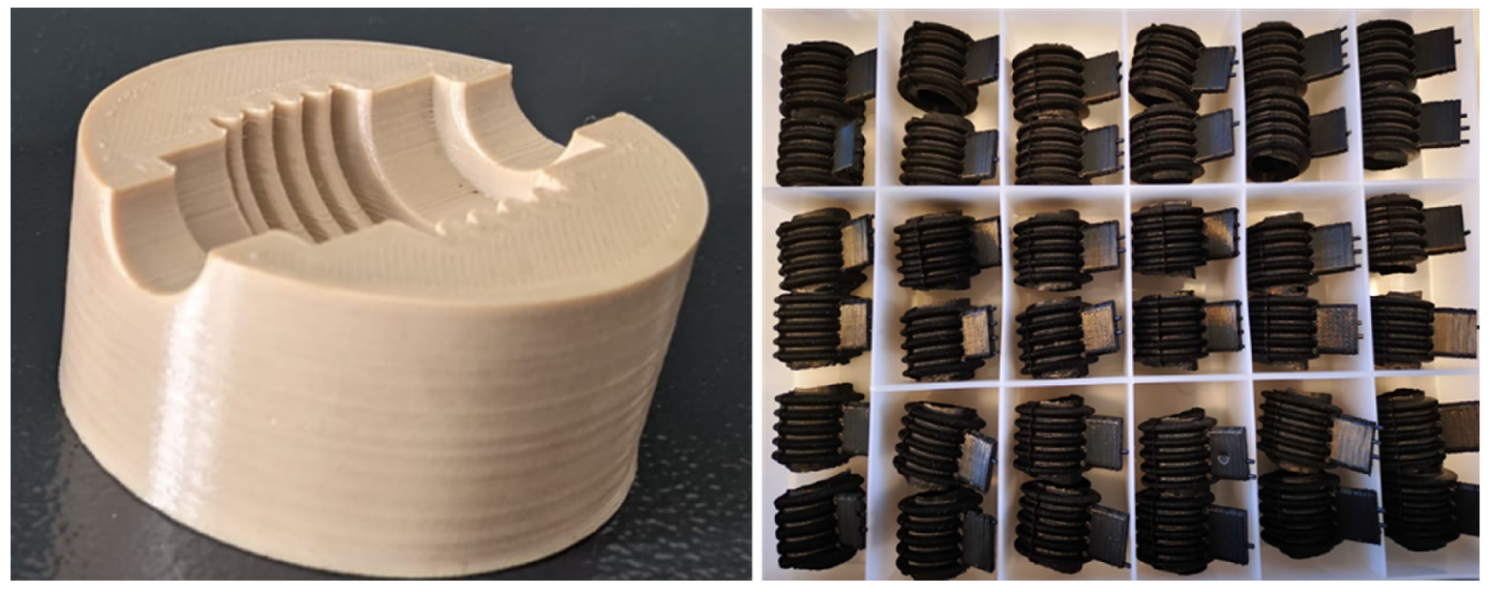
3.2. Laboratory Plant and Manufacturing

A specially developed and built FFF laboratory system was used for sample preparation. This is based on a gentry system and a build volume of 300 mm × 300 mm × 400 mm. The chamber is completely enclosed and insulated to ensure better temperature management. For temperature control, the nozzle temperature can be heated up to 500 °C and the build chamber up to 200 °C. The build platform can be heated up to 150 °C. To counteract warping and enable better adhesion of the components, the components were printed on a steel plate coated with “Vision Minor-Nano Polymer Adhesive”.

3.3. Samples

The unfilled “ThermaX PEEK” from the company 3DX-Tech was examined. To examine the starting material, sample segments were cut directly from the filament. The printed samples were cubes with the dimensions 20 mm × 20 mm × 2 mm. In the first series of experiments, one cube with a build chamber temperature of 90 °C and another cube with a temperature of 150 °C were manufactured. Here, the build platform heating with a temperature of 150 °C and a nozzle velocity of 20 mm/s remained constant for both samples. The specimens were printed solid and had a layer thickness of 0.15 mm. In addition, they were manufactured on a socalled raft, i.e., a printed construction plate. Based on the results, a mold out of PEEK was then annealed and used to manufacture 100 rubber components (Figure 1).

3.4. Thermal Post-Treatment
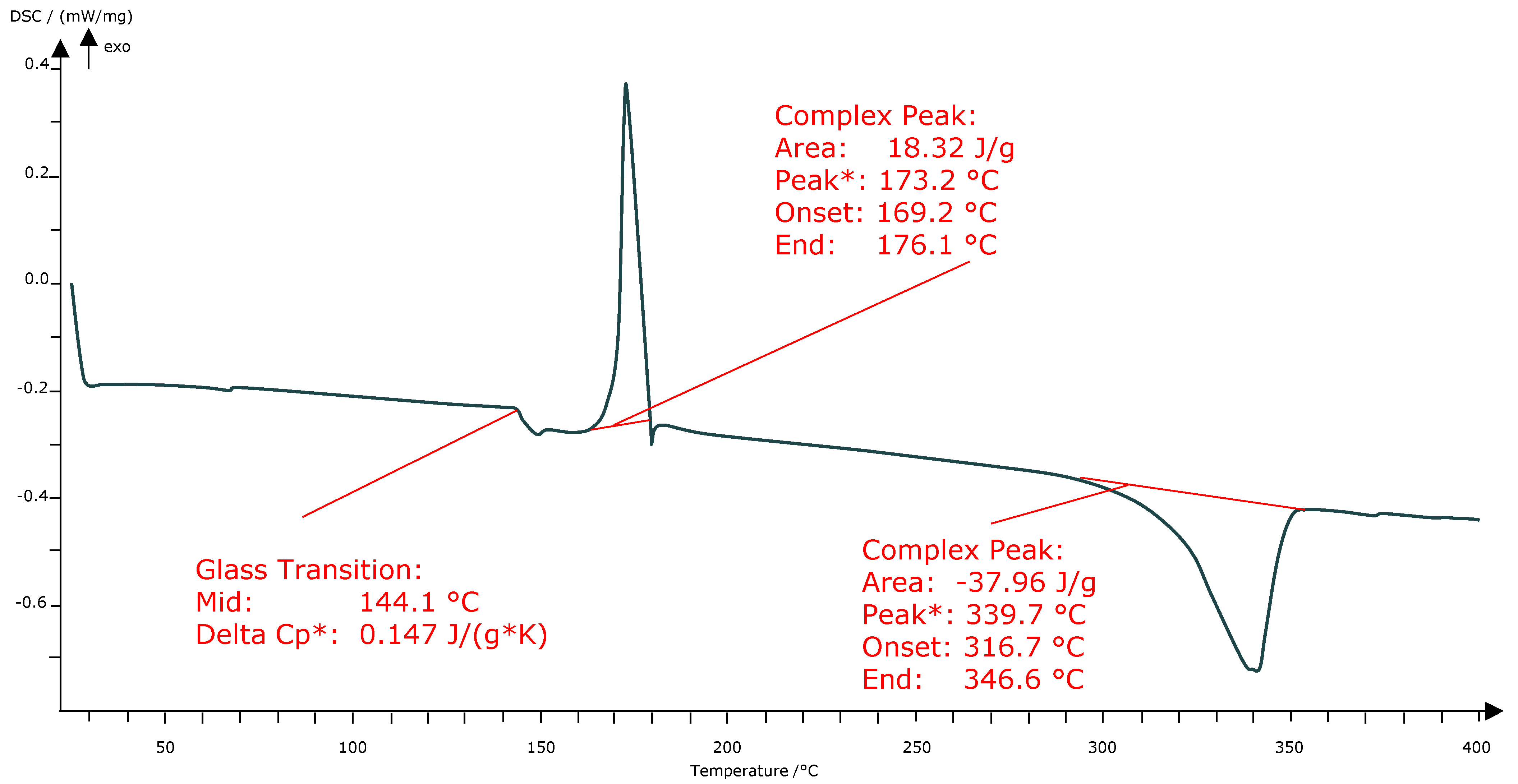
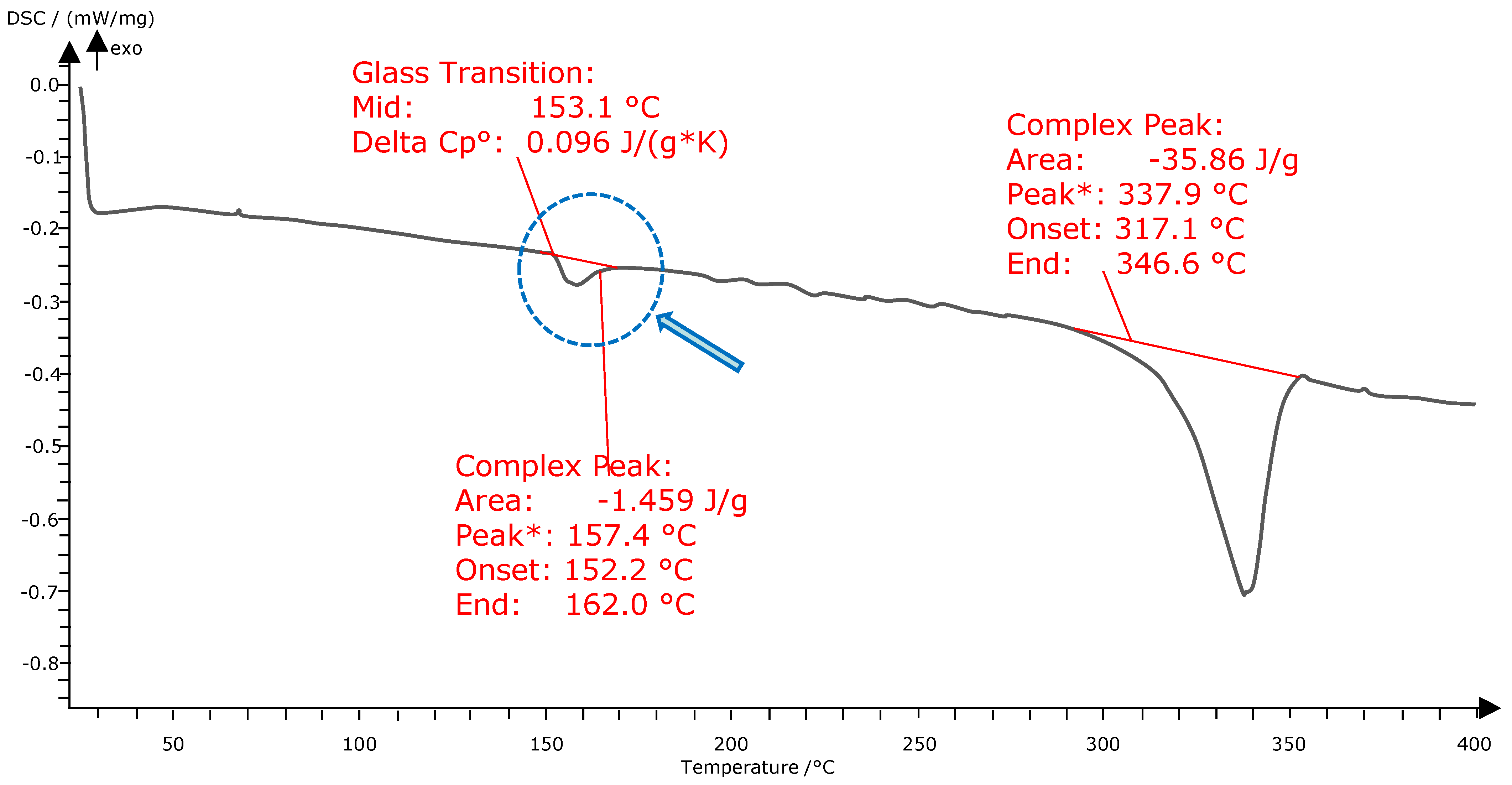
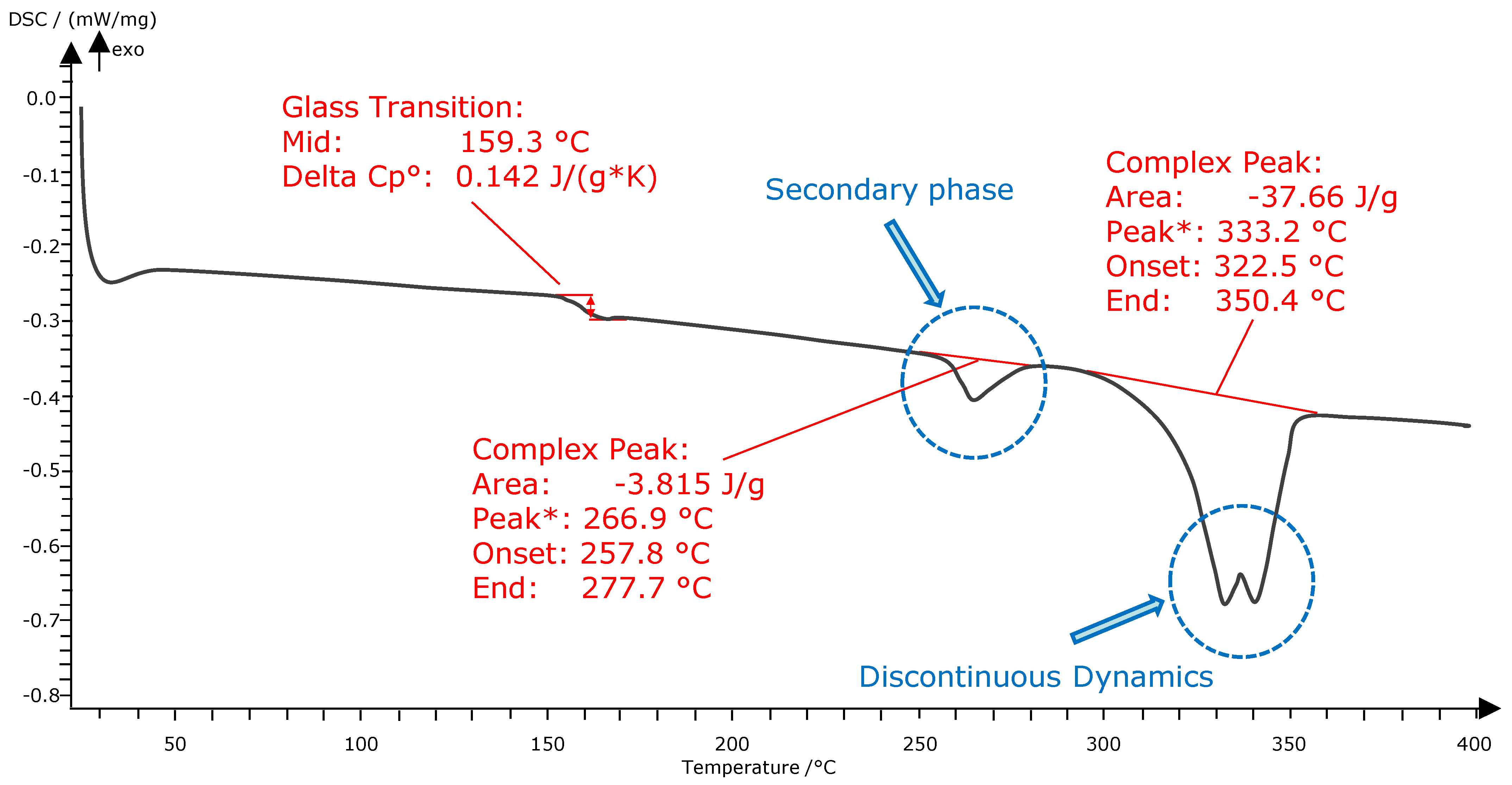
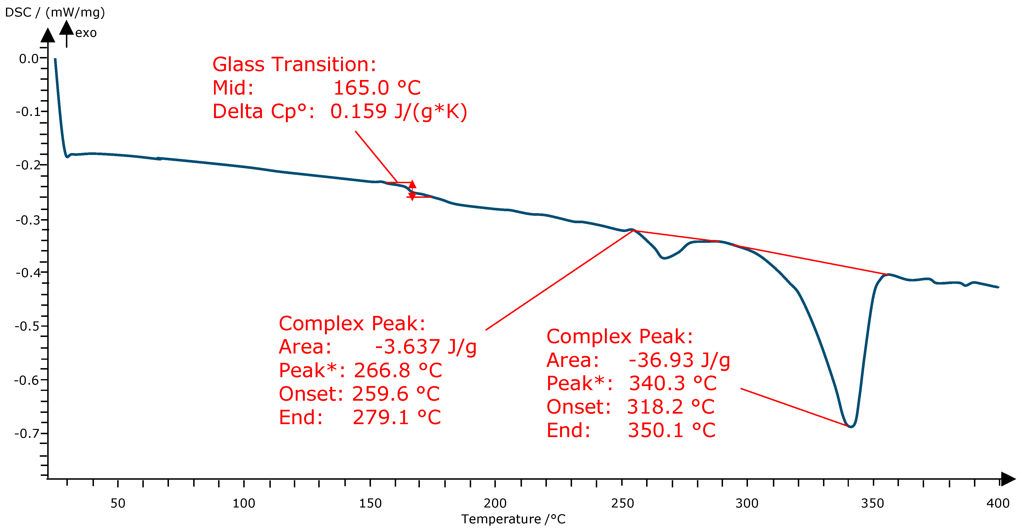
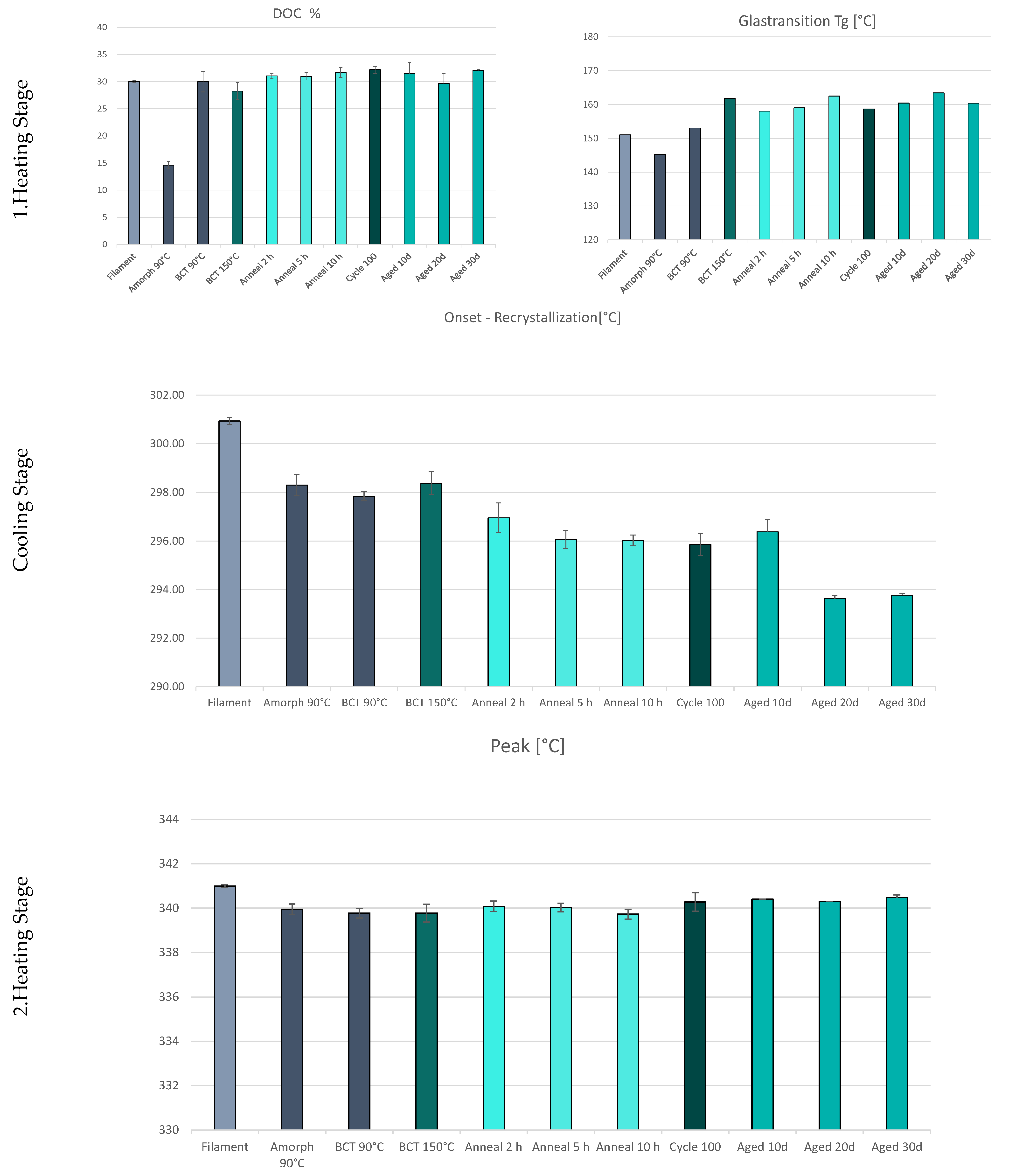
A 3DGence laboratory furnace was used for thermal post-treatment of the specimens. Thermal aging for postcrystallization took place here. The samples were heated up to the target temperature of 250 °C in a controlled manner within 11 h. Subsequently, they were kept at this temperature for 2 h, 5 h, and 10 h and cooled back to room temperature in 15 h. This ensures uniform cooling to avoid stress induction due to rapid cooling.

3.5. DSC Analysis

Differential Scanning Calorimetry was performed using a Netzsch DSC 204 F1. At least three samples with a mass of up to 10 mg were examined for each measurement. The samples were cut manually from the sample cubes. The test strategy was carried out by DIN 51007. For this purpose, the samples were heated at a heating rate of 10 K/min from 25 °C–400 °C and cooled down again at the same rate. The first heating process erased the previous material history, including the processing procedure and the thermal post-treatment, then heated to 400 °C. The material samples were tested in a perforated aluminum crucible. This allows the nitrogen purge gas to enter the crucible.

3.6. Tensile Test

Tensile test was performed using a Zwick Roell Zwick 10 kN tensile machine. In accordance with DIN EN ISO 527-1, bone-shaped specimens of type 1.BA were printed. The specimens were printed horizontally and with an infill density of 100%. The layer thickness was 0.1 mm. A preload of 1 MPa was selected and a test speed of 50 mm/min. At least three samples of the material were tested after FFF, after thermal post-treatment, and after further artificial aging of 10 to 30 days.

4. Results

4.1. Source Material

At the beginning of the process chain is the raw material, which serves as a reference point during the tests. According to the material data sheet, the glass transition temperature is 143 °C, and the processing temperature is in a range above the melting temperature. The first DSC of the material shows a deviation and opens so that the Tg from the material data sheet is lower than the determined one, at 150 °C. The degree of crystallization is at about 30%.

4.2. FFF Process—Build Chamber Temperature

In the following process step, processing takes place using FFF. A build chamber temperature below the Tg at 90 °C and just above the Tg at 150 °C was investigated. The samples processed at 90 °C have two visibly distinct regions, crystalline and amorphous. The amorphous region is visually distinguished by the partially transparent dark area, while the opaque region is crystalline. Components at an ambient temperature of 150 °C exhibit a homogeneous appearance. The DSC analysis makes the differences in temperature effects apparent. In the DSC analysis of the dark semitransparent region, an exothermic peak just above the glass transition temperature and a large endothermic region are visible (Figure 2). The exothermic region is a postcrystallization or cold crystallization. This is a clear indicator of amorphous material. The DOC of the amorphous region is only 14%. This results from the difference between the melting enthalpy areas (exothermic and endothermic).
Examination of the opaque region from the center of the sample showed a DOC twice as high. The comparison with the completely optically crystallized material (build chamber temperature 150 °C) indicates a similar DOC. Both are in the range of 29% DOC. It is interesting to note that all samples printed at a build chamber temperature of 90 °C show a pronounced relaxation curve after Tg (Figure 3). This has not been tested or determined in any other samples.

4.3. Annealed Samples

The subsequently annealed samples all exhibit a secondary phase approximately 15 °C above the annealing temperature at 265 °C. This secondary phase develops independently of the holding time in all samples. The expression of the phase is similar in all samples and has a DOC of 2.7–3%. The influence of the holding time on the expression of the DOC did not show any significant increase. Whereas previous amorphous phases exhibited almost double crystallinity, the maximum achieved value is about 31%. This also does not represent an increase compared to the starting material. However, it is worth mentioning that the Tg is raised and shifted by almost 10 °C compared to the starting source material and the amorphous phase. However, it is unclear why both samples at 2 h and at 10 h have a distinct melt pool (Figure 4) that exhibits discontinuous dynamics. This is not the case for 5 h. A first hint is given by the research work of Wang. et al. [23]. They found out by scanning electron microscope analysis that in PEAKs there are different primary and secondary structures with different sizes [23]. Due to the crystal size, the melting behavior can be influenced and is expressed discontinuously in the DSC.

4.4. Cyclus100 and Artificially Aged Material

The tested mold was annealed for 5 h based on the previous results. A clear secondary phase with the same enthalpy and the same location as the annealed samples can be seen. The mold shows, although not significantly, the highest DOC in the whole series of measurements with 32%. Otherwise, no irregularities can be seen (Figure 5).
The direct comparison of the individual process stages indicates further effects of thermal aging and the findings already obtained. As already expected, the curves of the first heating stage show the increase in an increased Tg in direct connection with a high degree of crystallization and a thermal post-treatment (Figure 6). This is especially clear by comparing the original material and material with very low DOC (amorphous sample). The deletion of the material history and subsequent reheating shows that all materials subsequently exhibit almost the same morphology as well as Tg. However, it is noticeable that the onset temperature of the crystallization displays a visibly decreasing tendency when the samples are cooled. With the increased aging and thermal stress, Tk has decreased by about 6 °C (Figure 6—Cooling Stage). Two stages are indicated here. Taking the filament material as a reference, the FFF process itself causes Tk to drop by 3 °C. After the annealing process itself, there is a noticeable drop in Tk around 3 °C. According to a study by Lee et al., who found a similar phenomenon with the variation of melting temperatures, the reason could already be a degradation phenomenon or increased crosslinking [12]. In this context, there is also the degradation of the additives used, initially added to the polymers to act as nucleating agents [3,4]. However, a resulting lower crystallization ability could not be found. Although there are slight changes in Tg and Tk, the melting point of the samples does not change. All of them have their peak after the second heating at about 340 °C (Figure 6—Second Heating Stage). Therefore, there are no other indicators of aging that can be seen from the DSC analyses. A change in melting temperature would indicate a change in molecular weight. With higher molecule weight, the melting temperature would increase. Degradation processes could increase the low molecular weight fraction, which would decrease the melting temperature. According to [13], the previously described double peak phenomenon in the melting range is still largely unexplained; only a connection to the morphology is suspected as Wang et al. found out [23].
The first tests did not provide complete information on aging and its effects on the material characteristics. Therefore, additional aging tests were carried out and supplemented by tensile tests. For this purpose, tensile specimens were manufactured and thermally aged in an oven at 200 °C for a period of 10–30 days. Where possible, the entire process chain was also considered. Printed untreated samples, annealed samples, and the aged samples were also examined as can be seen in Table 1.
The results clearly show that the first thermal post-treatment leads to an increase in tensile strength. The tensile strength was increased by 10 MPa. Further aging also led to an increase in tensile strength. However, after 20 and after 30 days, a clear reduction of the tensile strength is shown. This is due to further branching and crosslinking of the molecules. At the same time, the increasing crosslinking leads to an embrittlement of the material.

5. Conclusions and Discussion

PEEK is a very complex material, and its processing using additive manufacturing faces many challenges. The reason for this is the narrow process window and the temperature sensitivity during the processing. The study has shown insight into the material behavior and morphology over the entire process chain up to the loaded final product. The study focused on two main topics, the use of PEEK as mold material and, in this context, its material aging due to thermal stress. First and foremost, the study provided a first insight into the durability of a PEEK vulcanization tool in small series production. One hundred parts could be produced at 200 °C for 24 h without damaging the tool itself. In a first study, the DSC analysis also indicated the material aging, which could be detected by the crystallization and melting behaviors. Starting with the initial printing tests, the first DSC analyses show the immense influence of process parameters on the degree of crystallization. At 90 °C ambient temperature, the quenching process results in an almost amorphous region and a crystalline region located in the core, which has more time to crystallize due to slower cooling times. If the ambient temperature is maintained at a temperature equal to Tg, the temperature difference between the printed part and the build space is significantly reduced, minimizing the cooling rate. The resulting reduced cooling dynamics give the molecules more time to arrange and align. The phenomenon of two different phases is already known from the injection molding of PEEK. Molds that are too cold lead to amorphous areas in the boundary layers to the mold, while the DOC increases toward the center of the component. This leads to the recommendation to change the process parameters in order to decrease the cooling rate to ensure complete crystallization.
After printing, the DOC determined in this study is under 30%. However, according to literature and material manufacturers, a DOC of up to 40% is possible. The starting material already has a similarly high DOC. Based on the assumption that the material properties are improved with an increasing degree of crystallization, the test specimens, as well as the subsequent mold, were subjected to thermal post-treatment. A secondary phase is formed shortly above the annealing temperature in all thermally post-treated samples. However, the additional crystallization shows only a minimal increase in DOC. The holding time also did not improve the DOC. The analysis of the additional thermally loaded mold (24 h at 200 °C) as well as long-term-loaded mold (30 days) shows no significant deviations from the annealed samples. This is a first indication that the short-term loading has no considerable influence on the material properties. However, it should be mentioned that the cooling curve of the materials shows a clear trend towards a shift in crystallization temperature. This may be due to several reasons. The high and prolonged thermal stress may degrade the additives in the polymer, or it may degrade the polymer itself, which ultimately has an impact on nucleation. Both the printed specimens and the annealed material show increasingly lower onset temperatures in crystallization. Compared to other aging tests, the glass transition temperatures as well as melting temperatures show only minimal deviations and therefore do not provide any further conclusions on the aging behavior. The additional long-term study also only showed a change in the onset temperature. in combination with the tensile tests; however, it can be seen that there is a weakening of the material. The tensile strength decreases steadily and indicates an embrittlement of the material. In order to be able to better assess the tool life, targeted aging tests and TGA analyses will therefore be used in the future. At the same time, DMA analysis is used to describe the mechanical properties as a function of temperature.
This study contributes to a better understanding of thermal aging. For the first time, the entire process chain of FFF and rapid tooling using PEEK is highlighted, and thermal aging is discussed. In the context of vulcanization molding, the results contribute to the qualification of PEEK in the use of rapid tooling. In the future, the study will help to determine the influencing factors and the timing of material aging. It can be determined that thermal aging only influences recrystallization in a short period of time. The material properties only change after a continuous thermal load of more than 10 days. Thus, the service life and thus also the economic efficiency can be better estimated. In the context of sustainability and material recycling, it is also possible to assess the extent to which the material can be recycled.

Author Contributions

Conceptualization, K.A.; Methodology, K.A.; Validation, K.A. and N.B.; Formal Analysis, K.A. and M.S.; Investigation, K.A.; Resources, K.A.; Writing—Original Draft Preparation, K.A.; Writing—Review and Editing, K.A.; Visualization, M.S.; Final Approval N.B. and S.B.; Supervision, N.B. and S.B.; Project Administration, N.B. and S.B. All authors have read and agreed to the published version of the manuscript.

Funding

Funded by the University of Applied Sciences FH Aachen.

Data Availability Statement

Data are contained within the article.

Conflicts of Interest

The authors declare no conflict of interest.

References

  1. Gebhardt, A.; Hötter, J.-S. Additive Manufacturing: 3D Printing for Prototyping and Manufacturing; Hanser Publishers: Munich, Germany; Cincinnati, OH, USA, 2016. [Google Scholar]
  2. Kovács, J.G.; Szabó, F.; Kovács, N.K.; Suplicz, A.; Zink, B.; Tábi, T.; Hargitai, H. Thermal simulations and measurements for rapid tool inserts in injection molding applications. Appl. Therm. Eng. 2015, 85, 44–51. [Google Scholar] [CrossRef]
  3. Dizon, J.R.; Valino, A.D.; Souza, L.R.; Espera, A.H.; Chen, Q.; Advincula, R.C. 3D Printed Injection Molds Using Various 3D Printing Technologies. In Materials Science Forum; Trans Tech Publications Ltd.: Bäch, Switzerland, 2020; Volume 1005, pp. 150–156. [Google Scholar]
  4. Hopkinson, N.; Dickens, P. A comparison between stereolithography and aluminium injection moulding tooling. Rapid Prototyp. J. 2000, 6, 253–258. [Google Scholar] [CrossRef]
  5. Vidakis, N.; Petousis, M.; Vaxevanidis, N.; Kechagias, J. Surface Roughness Investigation of Poly-Jet 3D Printing. Mathematics 2020, 8, 1758. [Google Scholar] [CrossRef]
  6. Fortify, Injection Molded Materials with Fortify’s Tools—Fortify. 2020. Available online: https://3dfortify.com/molded-materials-fortify-mold-tools/ (accessed on 5 March 2022).
  7. Formlabs, Novus Applications setzt für Spritzguss von Prototypenformen auf Rigid 10K Resin. 2022. Available online: https://formlabs.com/de/blog/novus-applications-rigid-10k-resin/ (accessed on 26 August 2022).
  8. Kaiser, W. Kunststoffchemie für Ingenieure; Hanser: München, Germany; Wien, Austria, 2006. [Google Scholar]
  9. Eyerer, P.; Hirth, T.; Elsner, P. Polymer Engineering; Springer: Berlin/Heidelberg, Germany, 2008. [Google Scholar]
  10. Vassallo, M.; Rochman, A. Rapid prototyping solution for the production of vulcanized rubber components. In AIP Conference Proceedings; AIP Publishing LLC.: Melville, NY, USA, 2019; Volume 2113, p. 150014. [Google Scholar]
  11. Zanjanijam, A.R.; Major, I.; Lyons, J.G.; Lafont, U.; Devine, D.M. Fused Filament Fabrication of PEEK: A Review of Process-Structure-Property Relationships. Polymers 2020, 12, 1665. [Google Scholar] [CrossRef] [PubMed]
  12. Garcia-Leiner, M.; Ghita, O.; McKay, R.; Kurtz, S.M. Additive Manufacturing of Polyaryletherketones. In PEEK Biomaterials Handbook; Elsevier: Philadelphia, PA, USA, 2019; pp. 89–103. [Google Scholar]
  13. Ehrenstein, G.W.; Pongratz, S. Beständigkeit von Kunststoffen; Edition Kunststoffe; Hanser: München, Germany, 2007. [Google Scholar]
  14. Elsner, P.; Domininghaus, H. (Eds.) Kunststoffe: Eigenschaften und Anwendungen. In Mit 240 Tabellen. VDI-Buch, 7th ed.; Springer: Berlin/Heidelberg, Germany, 2008. [Google Scholar]
  15. Schönhoff, L.M.; Mayinger, F.; Eichberger, M.; Reznikova, E.; Stawarczyk, B. 3D printing of dental restorations: Mechanical properties of thermoplastic polymer materials. J. Mech. Behav. Biomed. Mater. 2021, 119, 104544. [Google Scholar] [CrossRef] [PubMed]
  16. El Magri, A.; Vanaei, S.; Vaudreuil, S. An overview on the influence of process parameters through the characteristic of 3D-printed PEEK and PEI parts. High Perform. Polym. 2021, 33, 862–880. [Google Scholar] [CrossRef]
  17. Abdullah, F.; Okuyama, K.; Morimitsu, A.; Yamagata, N. Effects of Thermal Cycle and Ultraviolet Radiation on 3D Printed Carbon Fiber/Polyether Ether Ketone Ablator. Aerospace 2020, 7, 95. [Google Scholar] [CrossRef]
  18. Mylläri, V.; Ruoko, T.-P.; Vuorinen, J.; Lemmetyinen, H. Characterization of thermally aged polyetheretherketone fibres—Mechanical, thermal, rheological and chemical property changes. Polym. Degrad. Stab. 2015, 120, 419–426. [Google Scholar] [CrossRef]
  19. Zhu, C.; Zhang, H.; Li, J. Thermal aging study of PEEK for nuclear power plant containment dome. J. Polym. Res. 2022, 29, 5. [Google Scholar] [CrossRef]
  20. Tardif, X.; Pignon, B.; Boyard, N.; Schmelzer, J.W.; Sobotka, V.; Delaunay, D.; Schick, C. Experimental study of crystallization of PolyEtherEtherKetone (PEEK) over a large temperature range using a nano-calorimeter. Polym. Test. 2014, 36, 10–19. [Google Scholar] [CrossRef]
  21. Day, M.; Suprunchuk, T.; Cooney, J.D.; Wiles, D.M. Thermal degradation of poly(aryl-ether–ether-ketone) (PEEK): A differential scanning calorimetry study. J. Appl. Polym. Sci. 1988, 36, 1097–1106. [Google Scholar] [CrossRef]
  22. Lee, A.; Wynn, M.; Quigley, L.; Salviato, M.; Zobeiry, N. Effect of Temperature History During Additive Manufacturing on Crystalline Morphology of Polyether Ether Ketone. arXiv 2021, arXiv:2109.04506. [Google Scholar]
  23. Wang, Y.; Beard, J.D.; Evans, K.E.; Ghita, O. Unusual crystalline morphology of Poly Aryl Ether Ketones (PAEKs). RSC Adv. 2016, 6, 3198–3209. [Google Scholar] [CrossRef] [Green Version]
Figure 1. PEEK Mold Half (left); Injection-molded rubber parts (right).
Jmmp 06 00093 g001
Figure 2. DSC- Four amorphous sample with distinct exothermic regions. * Maximal value of a peak in the selected range.
Jmmp 06 00093 g002
Figure 3. DSC-Crystalline region with relaxation curve. * Maximal value of a peak in selected range.
Jmmp 06 00093 g003
Figure 4. DSC-2 h annealed samples. * Maximal value of a peak in the selected range.
Jmmp 06 00093 g004
Figure 5. DSC-Mold material loaded with 100× cycles. * Maximal value of a peak in the selected range.
Jmmp 06 00093 g005
Figure 6. DSC-Results of the three DSC stages.
Jmmp 06 00093 g006
Table 1. Tensile strength depending on thermal post-treatment.
Leiyer Height 0.1 mmTensile Strength [MPa]
Post Treatment
None63.4
Annealing 250 °C73.8
10 days 200 °C80.6
20 days 200 °C75.2
30 days 200 °C70.6
Publisher’s Note: MDPI stays neutral with regard to jurisdictional claims in published maps and institutional affiliations.

