Article

Development of a Low-Cost Wire Arc Additive Manufacturing System

1
Department of Mechanical Engineering, California State University, Los Angeles, CA 90032, USA
2
Department of Aeronautical Engineering, Eskisehir Osmangazi University, Eskisehir 26040, Turkey
*
Author to whom correspondence should be addressed.
J. Manuf. Mater. Process. 2022, 6(1), 3; https://doi.org/10.3390/jmmp6010003
Submission received: 29 October 2021 / Revised: 16 December 2021 / Accepted: 17 December 2021 / Published: 24 December 2021
(This article belongs to the Topic Additive Manufacturing)

Abstract

:
Due to their unique advantages over traditional manufacturing processes, metal additive manufacturing (AM) technologies have received a great deal of attention over the last few years. Using current powder-bed fusion AM technologies, metal components are very expensive to manufacture, and machines are complex to build and maintain. Wire arc additive manufacturing (WAAM) is a new method of producing metallic components with high efficiency at an affordable cost, which combines welding and 3D printing. In this work, gas tungsten arc welding (GTAW) is incorporated into a gantry system to create a new metal additive manufacturing platform. Design and build of a simple, affordable, and effective WAAM system is explained and the most frequently seen problems are discussed with their suggested solutions. Effect of process parameters on the quality of two additively manufactured alloys including plain carbon steel and Inconel 718 were studied. System design and troubleshooting for the wire arc AM system is presented and discussed.

1. Introduction

Additive manufacturing (AM) is an alternative manufacturing method to conventional processes, such as casting and subtractive machining. This technology has gained considerable attention in the aerospace and automotive industries due to its many potential benefits, such as rapid prototyping, near-net-shape processing, component mass reduction, and geometric freedom. Initially developed around polymeric materials, the advancement of AM technology has pushed AM of high-density metallic materials to use a variety of high-power laser and welding-based technologies [1,2,3].
Metal-based AM processes often fit within two distinct principles of operation: powder bed fusion or direct energy deposition. The AM processes also differ by the heat source (e.g., laser, electron beam, and arc) and materials (e.g., powder, and wire) used in the deposition. In essence, almost all of the AM processes for the deposition of metallic materials are fundamentally repetitive welding processes.
The primary and universal principle of AM technologies involves the direct production of 3D objects from computer-aided design (CAD) data. These CAD data can be analyzed and converted into an additive manufacturing file format. From this, tool paths are then calculated and created from the slicing routine, and process parameters are derived, which are then uploaded to the specific AM equipment.
In a powder bed fusion system, material is distributed across the work area to form a thin metal powder layer. A programmed energy source transmits energy to the surface of the bed, thereby melting the powder to form the desired shape. After the additional powder is raked across the bed area, the process is repeated until desirable geometry is created. While powder bed fusion systems have the benefit of producing internal passages, high-resolution features, and maintaining dimensional accuracy, they suffer from disadvantages such as complicated set-ups, expensive equipment, and post-processing cleanup requirement [4,5].
In direct energy deposition systems, two basic strategies are used for depositing metal that is powder feeding and wire feeding. In powder feed systems, metallic powders are conveyed through a nozzle onto the build surface. The powders are then met by the energy source, melting a monolayer or more of the powder into the desired shape. This process is then repeated until the component is built. There are two possible configurations of the powder feed system. In one configuration, the workpiece remains stationary while the deposition head moves. In the second configuration, the deposition head remains stable and the workpiece is moved. The benefits of this type of system include larger build volumes and the ability to be used to refurbish damaged components. Drawbacks include expensive equipment such as laser and robotic systems, and post-processing cleanups [6,7].
In wire feed systems, the energy source may include electron beam, laser beam, or plasma arc. Typically, the plasma arc utilizes welding processes to generate the energy source. The material deposited is in the form of wire. A single bead of metal is deposited, and subsequent passes are built upon to develop a three-dimensional structure. The benefits of wire feed systems include a high deposition rate, huge build volumes, and less expensive equipment. When compared to traditional machining and subtractive manufacturing, the wire arc additive manufacturing (WAAM) systems can reduce fabrication time by 40–60% and post-machining time by 15–20% depending on the component size [8]. When comparing with powder bed fusion systems, the main drawbacks of WAAM systems are lower dimensional accuracy, difficulty in building complex geometries, and need for more extensive machining [6].
Gas metal arc welding (GMAW), gas tungsten arc welding (GTAW), or plasma arc welding (PAW) processes are usually used in wire arc additive manufacturing (WAAM). GMAW consists of a welding process in which an electric arc forms between a consumable metal inert gas (MIG) wire electrode and the workpiece metal. The formation of the electric arc heats the metal, causing it to melt and join. GTAW is a welding process that utilizes shielding tungsten inert gas (TIG) and a non-consumable tungsten electrode to produce the arc. PAW is a welding process similar to TIG; the critical difference from GTAW is that here the positioning of the electrode is within the body of the torch, and the plasma arc can be separated from the shielding gas.
Typically, WAAM systems utilize sophisticated robotic equipment to mobilize the torch component on a fixed workpiece and some use expensive CNC equipment to move the workpiece precisely into the desired positions. The central concept of WAAM is to produce a metallic part by melting a wire material using an electric arc in a layer-by-layer format [6,9,10].
Several researchers around the world have studied WAAM processes. In many cases, researchers have deployed WAAM systems through the use of GMAW processes due to their popularity, affordable welding equipment and, semi-automatic wire feed system [11,12]. For example, Rosli et al. developed a WAAM system by using MIG welding equipment [13]. The GTAW system provides some advantages over GMAW. The researchers at the University of Kentucky used a GTAW system to control the size and frequency of deposited droplets to improve deposition accuracy [14]. A GTAW system was also incorporated into a robotic arm to deposit material into specific geometric shapes and then with a five-axis CNC machine to smooth all surfaces [15]. Variations of these designs have been used in other systems. For instance, a six-axis welding robot, instead of CNC, allowed improved precision with larger travel movements [16]. The advantage of using GTAW can range from the variety of materials that can be deposited, finer weld beads, less heat input, less porosity, better mechanical properties and better surface finish [17,18]. Anzalone et al. also developed a low cost WAAM system by using delta bot and GMAW equipment [19].
Different metallic alloys can be used in WAAM systems; Williams et al. explained the usage of aluminum, titanium and steel parts that are mainly used in aviation industries such as landing gear assemblies, spars, wing ribs [20]. Gu et al. studied on different strategies such as cold working and heat treatment to increase strength in copper alloys [21]. Yan studied low thermal expansion coefficient Invar alloy composite mold tool repair with WAAM process [22].
WAAM-fabricated components are often comparable to their conventionally processed counterparts in terms of mechanical properties. However, WAAM processing may introduce some critical defects, such as porosity, residual stress and cracking. Defects in WAAM can result from a number of factors, including thermal deformation due to heat accumulation, an unreliable programming strategy, an unstable welding pool, and contamination from the environment. There is typically severe oxidation in titanium alloys, porosity in aluminum alloys, poor surface roughness in steel, and severe deformation and cracks in nickel alloys [5].
The safety issues of WAAM systems are similar to those of traditional welding processes. Therefore, good ventilation, protective equipment against metal fumes and excessive heat and light are required [23].
In this study, a low-cost wire-arc additive manufacturing (WAAM) system is designed that offers an alternative solution to develop and repair high-value metallic components. The applications include repair and manufacturing of parts such as fittings, implants, heat exchangers in aviation, automobile and medical industries [24]. The system incorporates an open-source 3D printer and gas tungsten arc welding (GTAW) process. The system costs around $1000 and includes open source fused deposition modeling (FDM) 3D printer parts, microcontroller, TIG welder, and specially designed and produced parts, such as a torch holder, among other components. The computer and gas container were excluded from this cost estimate. This design approach eliminates the use of expensive equipment, such as a robotic arm, thus reducing the price of the machine drastically. This low-cost AM machine also implements an open-source architecture.

2. Materials and Methods

2.1. Design Process

The WAAM system consists of mechanical and electrical components, as well as dedicated software. The main components of the WAAM system are depicted in Figure 1.

2.1.1. Mechanical Design

The main frame of the system is similar to the design concept of traditional fused deposition modeling (FDM) 3D printers. The Cartesian gantry system was inspired by an open-source design called Bukobot [25,26], consisting of a z-axis vertical square frame and a perpendicular x-y axis carriage.
The frame of the system was manufactured using traditional machining processes. In addition, some elements were sectioned using water jet cutting. The open-source concept lays the foundation to build a low-cost system. The freedom to design and manufacture custom components using 3D printing allowed the fabrication of many holders and joints specific to this system. For the assembly of the structure’s frame more than 40 components were made out of acrylonitrile butadiene styrene (ABS) thermoplastic polymer using a Stratasys U-plus 3D printer. The heat source was a constricted arc that was implemented using the Everlast 150 GTAW welding machine. The machine was capable of supplying welding current in the range of 5–150 amps, with a high frequency or lift arc start. A 1.8 cm cup size with 2% thoriated tungsten was utilized to strike an arc, and the tungsten electrode distance from the tipping point to the ceramic cup was recommended to be 4–9 mm, depending on the job [27].
The material used for metal deposition was provided as a spool of wire, which was fed by an auto-feeder mechanism. The alloy was laid in front of the moving melting pool through an annular feed nozzle connected to a custom-made wire feeder. As seen in Figure 2, the auto-feeder mechanism was set to the left of the welding torch, and wire material was pushed from top to bottom in front of the moving melting pool. The material deposition direction was from right to left in the x-axis, as seen in Figure 2.

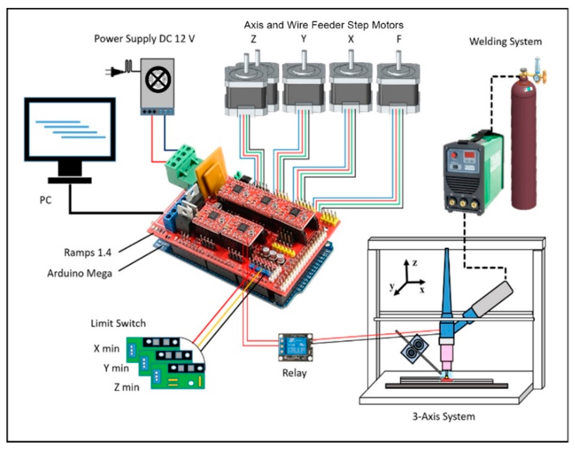
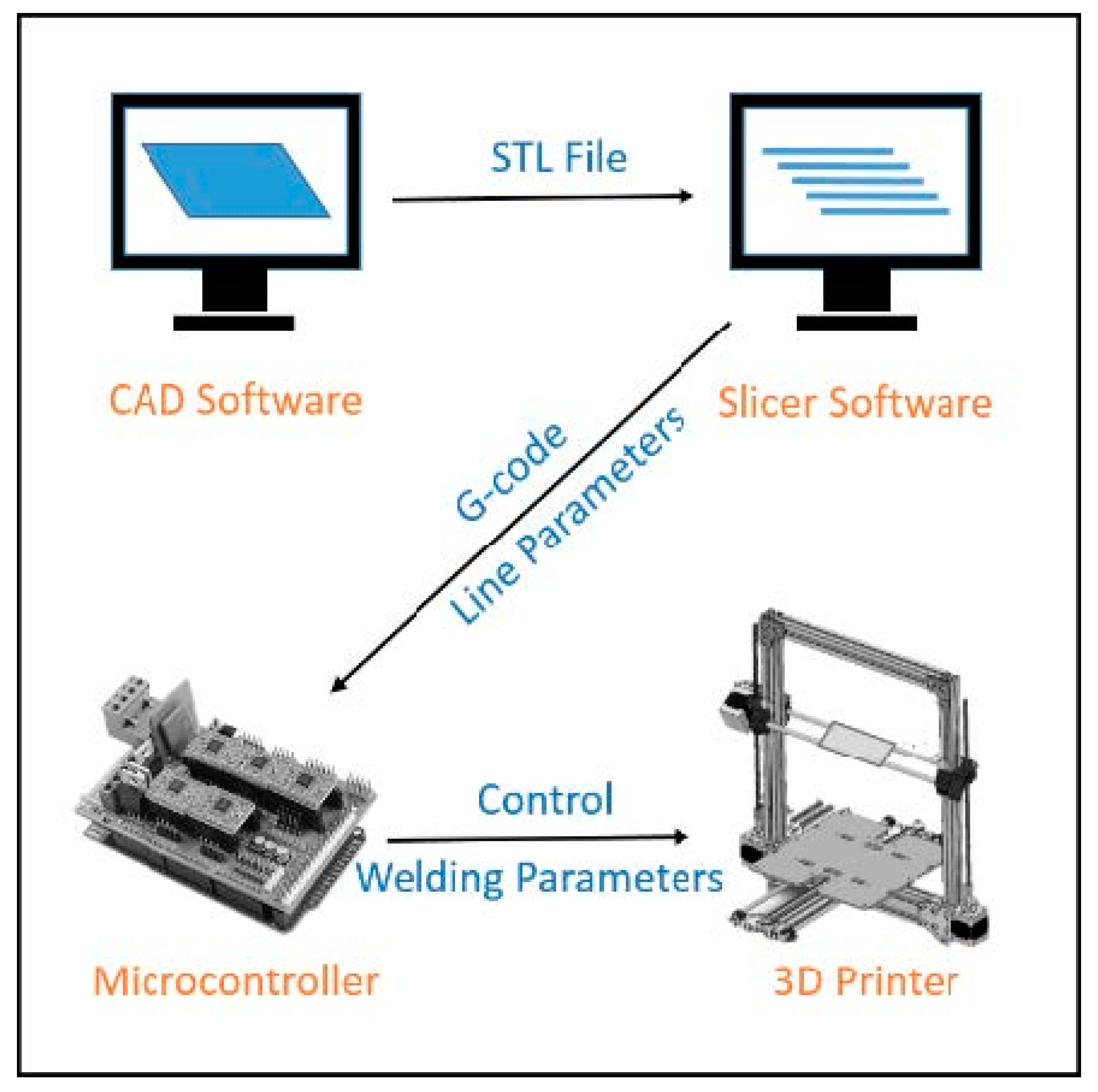
2.1.2. Electrical Design and Programming

The process control and programming of the WAAM system in this work are based on an open-source architecture. It consists of a host, firmware, slicer, and modeling software, each having a unique input on preparing the adequate instructions to manufacture an object. Marlin [28] is an open-source firmware that is the core of the microcontroller. The microcontroller is an Arduino-based controller board (Arduino Mega 2560®, Torino, Italy) designed for RepRap 3D printer platforms and is used to establish a connection between welding equipment and the gantry system. The CAD model of the 3D object is transferred to the host software, Repetier (Ver. 2.0.5) [29]. In the host program, the object is transformed into a specific set of commands called G-code, using a 3D modeling slicer software [30]. The Arduino controller serves as a receiver that translates these G-code commands into mechanical movements and welding equipment instructions.
The Arduino Mega microcontroller receives the specific G-code instructions to give directions to electronic components as to when to turn on or off. A 12-V DC power was selected to give the necessary power to all parts (welding equipment was connected separately). One key component that makes this system work properly is the addition of a relay switch connected between the microcontroller and the welding torch trigger; this allows to achieve “START” and “STOP” functions to control the welding arc. Figure 3 illustrates the flow process of creating an object from a 3D CAD model to a metal 3D printed model. CAD software is utilized to develop a parametric 3D model. The file is then converted to a standard triangle language (STL) format. The STL file is reprogrammed and recompiled using slicing software, which then is translated to G-code commands. The commands generated are then sent to the microcontroller, where they are converted into pulses to the motors, simultaneously giving instructions on when to turn the welding torch equipment to deposit the material.
Upon receiving a print job, the system controller resets all current positions and moves the stage and the TIG torch into their initial positions using end-stops. The arc is then initiated automatically, and the torch moves at a relatively constant speed within the x-axis, laying material in the pattern dictated by the G-code. The model is built in the x-z direction uniformly, adding and padding one continuous bead on top of another until the entire height of the model is created. Upon conclusion of printing, the welding arc and the wire feeder shut down, and the welding torch moves away from the deposited material.

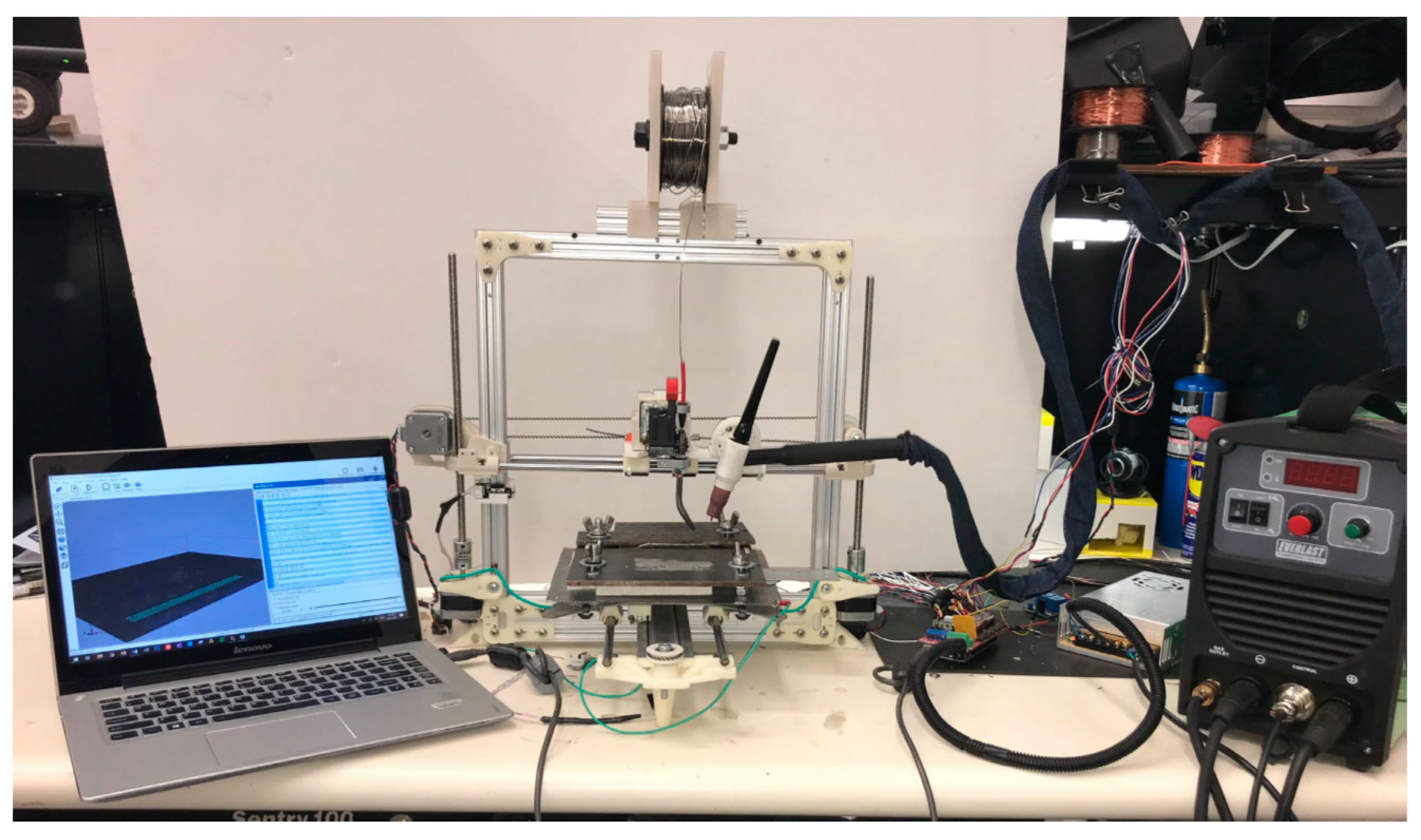
2.2. Design Validation and Experimental Setup

Plain carbon steel AISI 1030 and Inconel 718 wires were used for testing the system. The reason behind selecting AISI 1030 steel was its high weldability. The welding consumables and settings used for testing with the plain carbon steel and Inconel 718 are listed in Table 1.
Preliminary testing of the proposed low-cost WAAM system consisted of selecting the ideal parameters that affect how the machine behaves. The chosen settings that were carefully considered to be the driving factors in depositing material were: wire-feed speed, torch travel speed, and electrical current. A series of experimental trials with these factors in mind were performed to see how the machine behaves, how the welding arc forms a melting pool, and how the wire interacts with the melting pool. Throughout testing, all three variables were dependent on each other. When the travel speed increased, the wire feed speed and amperage needed to be increased. When the travel speed decreased, the wire feed speed and amperage needed to be decreased. To understand how the process parameters, affect the weld lines, a design of experiment (DoE) methodology was employed. The selected parameters are given in Table 2.
After performing single-pass tests for each parameter set and material, multi-pass tests were performed to build a wall. The microstructure of the samples were evaluated under an optical microscope to reveal the solidifying microstructure and characterize the process.
Once the steel experiments were completed, the same experimental steps were applied to Inconel 718 alloy. Inconel 718 is a nickel-based, precipitation-hardened superalloy. The motivation behind choosing Inconel 718 was its versatility. This alloy has been widely used in many critical industries, such as aerospace, medical, energy, etc. [31]. Metal additive manufacturing is also mostly utilized in these industries today. The design of experiments data for Inconel 718 are shown in Table 3.

3. Results

3.1. Encountered Difficulties during Design

During the first stage of experimental trials, there were many problems encountered, such as mechanical components not functioning correctly, not responding to commands, loss of power, electrical connections getting burned or overheated, and software commands not being executed according to the code. Another major problem encountered during the work was the system shutting down unexpectedly and not being able to create a consistent welding arc. One of the leading causes of these difficulties was determined to be electromagnetic interference (EMI) due to the high frequency when the welding arc was initiated. The EMI noise created by the welding torch affected the functionality of electronic components, such as stepping motors not responding to commands sent by the computer. Another component affected by EMI was the one that created this noise from the beginning, the welding torch. The welding torch would strike the welding arc with the substrate material and would not turn off when prompted. One solution that helped reduce EMI in the system was clipping ferrite couplers to all wired electronic connections, doing this reduced the amount of EMI produced by the welding torch. Many of these difficulties are listed in Table 4, detailing the affected components, and explaining possible solutions to these challenges.
The top view of the single lines, and side view of the multilayer plain carbon steel samples are shown in Figure 4 and Figure 5, respectively. Based on the results shown in Figure 4 for the single-line experiments, the parameter sets 1, 2, 3, and 5 had inconsistent results. These sample sets produced droplet-like deposits rather than continuous weld beads. Parameter sets 1, 2, and 3 show that lower arc current cannot produce a stable continuous molten pool. The minimum welding current required for steel samples under these experimental conditions is 50 A. Parameter set #5 produced a similar result even with 50 A due to its high travel speed. Cold welding conditions were created as the welding current decreased, the wire feed speed increased, and the travel speed increased. There must be a balance between the parameters of current, wire feed speed, and travel speed. The remaining parameter sets provided continuous weld beads that were free from voids, inclusion, or cracks. The most promising set of parameters was #8 with minimal variations in weld width and height, which means that stable molten pool size and solidification rate were achieved throughout the entire weld. Parameter set #8 was used to perform multi-pass tests and build a wall, as depicted in Figure 5.
The test results for Inconel 718 single lines are shown in Table 5.
Figure 6 shows the transverse (perpendicular to the building direction) metallographic sections of the single-pass samples, illustrating dendritic microstructure and columnar grains in the beads. The weld height, weld width, penetration depth, and wetting angles were measured for the nine Inconel samples and presented in Table 5. No indication of crack, lack of fusion, oxidation, inclusion, or porosity-type defects were observed in any of the samples. The weld transverse sections had good symmetry around weld centerline; the right and left sides of the weld beads were almost equal size and shape. Metal deposition efficiency can be influenced by both the bead height and the bead width. For continuous deposition, the width is a reference factor for determining the overlap amount between each bead. The number of layers is determined by the bead height [32]. The measured data indicates how the input parameters and weld bead characteristics are correlated. Welding current is the most influential parameter. Figure 7 shows that increasing welding current results in an increase in the bead width. The weld width also increases when welding current and wire feed rate increase together. Travel speed is reversely proportional to the weld width, due to less deposited metal per length under constant feed rate. The wetting angle is directly proportional to the penetration depth; higher wetting angel is associated with deeper penetration depth, as shown in Figure 8. The shape properties such as symmetry, width, and wetting angle of the layers must be controlled precisely to achieve dimensional accuracy when building up layers.
The longitudinal metallographic section of the 30-layer deposition of Inconel 718 alloy are given in Figure 9 and Figure 10, showing typical columnar microstructure. The microstructural analysis showed that the designed system was able to produce a simple wall with promising properties. Defects, such as oxidation between layers, crack, and inclusion, were not observed.

3.2. Encountered Difficulties during Design Validation

After each deposition experiment, each weld line was examined visually to see if there were any imperfections. The surface waviness (humping) problem was seen as the number of the depositing layers increases. Once the humping occurred in any layer, the weld quality worsened with each successive layer. As a nature of the direct energy deposition (DED) processes, each new layer is directly affected by the previous layer. It is believed that fluctuations of wire feed rate and z-axis height variations of torch assembly during the deposition were the main causes of the humping problem. To provide better results, many fixes to the auto feeder mechanism and torch assembly were made. The first designed feeder and torch holder assembly parts had some rigidity and positioning accuracy problems. Additionally, the heat exerted from the torch caused overheating and softening of the 3D printed parts. Revisions and redesign procedures were made to reinforce the structural parts, and also hold the torch far from heated areas for better positioning and heat management. The revised WAAM system with improved fixtures and modified assemblies is shown in Figure 11. Although this design was more stable than previous versions, it could not produce complex geometries with precise dimensions. The deposition process needed more precise adjustments as the number of layers were increased. The distances and angles between torch tip, deposited layer and wire feeder need be adjusted dynamically throughout the process by using closed loop control system.
Another problem during deposition also appeared during the multi-layer deposition process. Although the endpoint keeps constant in building a single wall, the line length got shorter after each layer. Therefore, the very end edge of the built wall became tapered instead of being perpendicular to the base plate. The reason behind this problem comes from the deposition characteristic of the GTAW process. The molten metal is deposited behind the arc. Since there is no further movement at the end point, and newly deposited metal does not fill the area under the arc and makes the wall length shorter than the arc traveling length. To mitigate the tapering problem, the end point of each line was set to be 2 mm longer for each deposited layer. In addition, wire feed rate was increased by 10% at the last 5 mm of the travel path, which mitigated the problem to some extent but did not eliminate it. As the number of layers increased, this solution did not work properly. Figure 12 shows the results of a 30-layer wall structure deposited using Inconel 718 wire.

4. Conclusions

It was demonstrated that a standard 3D gantry system which is widely used in fused deposition modeling (FDM) 3D printers can be modified to build a WAAM metal 3D printer. Special fixtures, such as a torch holder and wire feeding system, were designed. The proposed design offers an affordable system for 3D printing metallic components that can be of particular interest for repair applications.
The main limitations of the designed system are the dimensional limitation of the repaired or fabricated part, the absence of additional axis movements of the torch and sample, and the limited environmental protection of the solidified metal from the atmosphere. Some of these restrictions can be addressed by using the larger frame and using an additional enclosed inert gas filled shielding chamber to isolate the hot metal from the air. Although there is no serious risk to the operator, due to its fully automatic remote operation, the protective chamber will also increase the safety of the operator by blocking the extremely bright and hot arc. It is also worth noting that WAAM should be performed in a well-ventilated area to protect the operator from metal vapors.
Nevertheless, the proposed system together with proper process parameters can be used with many metallic alloys that can be processed by GTAW and WAAM, with less effort and lower cost compared to the expensive powder-bed systems [5]. Some examples of the alloys that can be processed include titanium alloys, aluminum alloys, nickel-based superalloys, cobalt-based superalloys, and low alloy steels.
In this work, design and build of a simple, affordable, and effective wire arc additive manufacturing (WAAM) machine was presented. This inexpensive system was made with a budget of approximately $1000 by integrating a GTAW welding machine into a cartesian gantry. The open-source architecture allowed the implementation of different methods to manipulate and control the additive manufacturing process. Open-source software Repetier was utilized to control all aspects of the machine, providing the flexibility to manipulate movements of mechanical components through a laptop computer. Preliminary testing was conducted to learn how the custom made WAAM machine would behave when depositing engineering alloys. Adjustments to the system were incorporated to make the machine more reliable. Even though WAAM systems are candidates to replace conventional methods of manufacturing metal components, a substantial need for research still exists to make this revolutionary manufacturing process acceptable for industrial applications.
Although some challenges still could not be solved due to the nature of the WAAM process and designed system characteristics, the most frequently seen problems during design were addressed with their related suggested solutions. Nevertheless, there is still a need for automatic distance adjustment between the torch tip and the work piece to achieve more consistent results. The angles and distances between wire tip, torch tip, and work piece should be precisely adjusted and kept fixed throughout the process. These demands may be fully satisfied by the deployment of a closed-loop control system in future works. The design presented here proves the potential of a cost effective WAAM system developed by using FDM printer frame and open source software after applying the recommended additions.

Author Contributions

Conceptualization, M.E., M.N., A.M. and S.F.D.; methodology, M.E., M.N., A.M. and S.F.D.; software, M.N., A.M. and S.F.D.; validation, M.N., A.M. and S.F.D.; formal analysis, S.F.D., M.N. and A.M.; investigation, M.N., A.M. and S.F.D.; resources, M.E.; data curation, S.F.D., M.N. and A.M.; writing—original draft preparation, M.N. and A.M.; writing—review and editing, S.F.D. and M.E.; supervision, M.E. and S.F.D.; project administration, M.E.; funding acquisition, M.E. All authors have read and agreed to the published version of the manuscript.

Funding

This research received no external funding.

Data Availability Statement

Not applicable.

Acknowledgments

The authors would like to acknowledge the help of Jonathan Yoshioka with post processing and reproducing some of the figures. The authors also acknowledge California State University, Los Angeles, CA, USA, for supporting this project.

Conflicts of Interest

The authors declare no conflict of interest.

References

  1. Cooper, D.E.; Stanford, M.; Kibble, K.A.; Gibbons, G.J. Additive Manufacturing for product improvement at Red Bull Technology. Mater. Des. 2012, 41, 226–230. [Google Scholar] [CrossRef] [Green Version]
  2. Gebhardt, A.; Schmidt, F.-M.; Hötter, J.-S.; Sokalla, W.; Sokalla, P. Additive Manufacturing by selective laser melting the realizer desktop machine and its application for the dental industry. Phys. Procedia 2010, 5, 543–549. [Google Scholar] [CrossRef] [Green Version]
  3. Mazzoli, A.; Germani, M.; Raffaeli, R. Direct fabrication through electron beam melting technology of custom cranial implants designed in a PHANToM-based haptic environment. Mater. Des. 2009, 30, 3186–3192. [Google Scholar] [CrossRef]
  4. Srivatsan, T.S.; Manigandan, K.; Sudarshan, T.S. Additive Manufacturing of Materials Viable Techniques, Metals, Advances, Advantages, and Applications. In Additive Manufacturing; Srivatsan, T.S., Sudarshan, T.S., Eds.; CRC Press Taylor & Francis Group: Boca Raton, FL, USA, 2016; pp. 1–43. [Google Scholar]
  5. Wu, B.; Pan, Z.; Ding, D.; Cuiuri, D.; Li, H.; Xu, J.; Norrish, J. A review of the wire arc additive manufacturing of metals: Properties, defects and quality improvement. J. Manuf. Process. 2018, 35, 127–139. [Google Scholar] [CrossRef]
  6. Frazier, W. Metal Additive Manufacturing: A Review. J. Mater. Eng. Perform. 2014, 23, 1917–1928. [Google Scholar] [CrossRef]
  7. Gibson, B.S.I.; Rosen, D. Additive Manufacturing Technologies, 2nd ed.; Springer: New York, NY, USA, 2015. [Google Scholar]
  8. Ribeiro, F. 3D printing with metals. Comput. Control. Eng. J. 1998, 9, 31–38. [Google Scholar] [CrossRef]
  9. Bikas, H.; Stavropoulos, P.; Chryssolouris, G. Additive Manufacturing Methods and Modelling Approaches: A Critical Review. Int. J. Adv. Manuf. Technol. 2016, 83, 389–405. [Google Scholar] [CrossRef] [Green Version]
  10. Spencer, J.D.; Dickens, P.M.; Wykes, C.M. Rapid prototyping of metal parts by three-dimensional welding. Proc. Inst. Mech. Eng. Part B J. Eng. Manuf. 1998, 212, 175–182. [Google Scholar] [CrossRef]
  11. Almeida, P.M.S.; Williams, S. Innovative process model of Ti-6Al-4V additive layer manufacturing using cold metal transfer (CMT). In Proceedings of the Twenty-First Annual International Solid Freeform Fabrication Symposium; University of Texas at Austin: Austin, TX, USA, 2010. [Google Scholar]
  12. Pickin, C.G.; Young, K. Evaluation of Cold Metal Transfer (CMT) Process for Welding Aluminum Alloy. Sci. Technol. Weld. Join. 2006, 11, 583–585. [Google Scholar] [CrossRef]
  13. Rosli, N.A.; Alkahari, M.R.; Ramli, F.R.; Maidin, S.; Sudin, M.N.; Subramoniam, S.; Furumoto, T. Design and Development of a Low-Cost 3d Metal Printer. J. Mech. Eng. Res. Dev. (JMERD) 2018, 41, 47–54. [Google Scholar] [CrossRef]
  14. Zhang, Y.M.; Yiwei, C.; Pengjiu, L.; Alan, T.M. Weld deposition-based rapid prototyping: A preliminary study. J. Mater. Process. Technol. 2003, 135, 347–357. [Google Scholar] [CrossRef]
  15. Merz, R.; Prinz, F.; Ramaswami, K.; Terk, M.; Weiss, L. Shape Deposition Manufacturing, Engineering Design Research Center; Carnegie Mellon University: Pittsburgh, PA, USA, 1994. [Google Scholar]
  16. Singh, S.; Sharma, S.K.; Rathod, D.W. A Review on Process Planning Strategies and Challenges of WAAM. Mater. Today Proc. 2021, 47, 6564–6575. [Google Scholar] [CrossRef]
  17. Rosli, N.A.; Hasan, R.; Sudin, M.N. Review of wire arc additive manufacturing for 3D metal printing. Int. J. Autom. Technol. 2019, 12, 346–353. [Google Scholar]
  18. Karayel, E.; Bozkurt, Y. Additive Manufacturing Method and Different Welding Applications. J. Mater. Res. Technol. 2020, 9, 11424–11438. [Google Scholar] [CrossRef]
  19. Anzalone, G.C.; Zhang, C.; Wijnen, B.; Sanders, P.G.; Pearce, J.M. A Low-Cost Open-Source Metal 3-D Printer. IEEE Access 2013, 1, 803–810. [Google Scholar] [CrossRef]
  20. Williams, S.W.; Martina, F.; Addison, A.C.; Ding, J.; Pardal, G.; Colegrove, P. Wire + Arc Additive Manufacturing. Mater. Sci. Technol. 2016, 32, 641–647. [Google Scholar] [CrossRef] [Green Version]
  21. Gu, J.; Ding, S.W.; Williams, H.; Gu, J.; Bai, Y.; Zhai, Y. The strengthening effect of inter-layer cold working and post-deposition heat treatment on the additively manufactured Al–6.3Cu alloy. Mater. Sci. Eng. A 2016, 651, 18–26. [Google Scholar] [CrossRef] [Green Version]
  22. Lihao, Y. Wire and Arc Additive Manufacture (Waam) Reusable Tooling Investigation. Master’s Thesis, School of Applied Science, Welding Engineering, Cranfield University, Cranfield, UK, 2013. [Google Scholar]
  23. Nagarajan, H.P.N.; Panicker, S.; Mokhtarian, H.; Coatanéa, E.; Haapala, K.R. Improving worker health and safety in wire arc additive manufacturing: A graph-based approach. Procedia CIRP 2020, 90, 461–466. [Google Scholar] [CrossRef]
  24. Our Finest Use Cases | FIT Additive Manufacturing Group. Available online: Fttps://fit.technology/usecases_en.php (accessed on 6 December 2021).
  25. Mastering 3D Printing—Joan Horvath—Google Books. Available online: https://books.google.com.tr/books/about/Mastering_3D_Printing.html?id=XFInCgAAQBAJ&printsec=frontcover&source=kp_read_button&redir_esc=y#v=onepage&q&f=false (accessed on 19 July 2021).
  26. Bukobot 3D Printer—Deezmaker 3D Printing. Available online: https://deezmaker.com/products/bukobot-3d-printer/ (accessed on 19 July 2021).
  27. Davies, A.C. The Science and Practice of Welding, the Pittbuilding, Trumpington Street; The Press Syndicate of the University of Cambridge: Cambridge, UK, 1993; Volume 2. [Google Scholar]
  28. Marlin Firmware. Available online: https://marlinfw.org/ (accessed on 19 July 2021).
  29. Repetier Software. Available online: https://www.repetier.com/ (accessed on 20 July 2021).
  30. Cura, U. Advanced 3SD Printing Software Made Accessible. Available online: https://www.ultimaker.com/en/products/ultimaker-cura-software (accessed on 5 November 2018).
  31. Zhang, L.N.; Ojo, O.A. Corrosion behavior of wire arc additive manufactured Inconel 718 superalloy. J. Alloy. Compd. 2020, 829, 154455. [Google Scholar] [CrossRef]
  32. Kim, J.; Pyo, C. Comparison of Mechanical Properties of Ni-Al-Bronze Alloy Fabricated through Wire Arc Additive Manufacturing with Ni-Al-Bronze Alloy Fabricated through Casting. Metals 2020, 10, 1164. [Google Scholar] [CrossRef]
Figure 1. Schematics of the components of the WAAM system.
Jmmp 06 00003 g001
Figure 2. Assembly of the WAAM system components.
Jmmp 06 00003 g002
Figure 3. The process of 3D printing an object from a 3D CAD model.
Jmmp 06 00003 g003
Figure 4. Deposited steel single-passes using the design of experiments parameters. The experiment numbers listed in Table 2 can also be seen in this figure.
Jmmp 06 00003 g004
Figure 5. Deposited steel 25-layer wall structure produced with parameter set #8 in Table 3.
Jmmp 06 00003 g005
Figure 6. The transverse (perpendicular to the building direction) metallographic sections of the single-pass Inconel 718 samples. The processing parameters as well as characteristic measurements for the samples with corresponding parameter set numbers are presented in Table 5.
Jmmp 06 00003 g006
Figure 7. The relation between welding current, travel speed, welding feed rate (WFR), and weld width for Inconel 718 single-pass samples.
Jmmp 06 00003 g007
Figure 8. The relation between penetration depth vs. wetting angle for Inconel 718 single-pass samples. The number on the data points indicate the experiment numbers.
Jmmp 06 00003 g008
Figure 9. Cross section of in the x-z plane (x being the torch moving direction and z being the height) of the Inconel 718 30-layer wall structure.
Jmmp 06 00003 g009
Figure 10. Detailed microstructural section of the x-z plane (x being the torch moving direction and z being the height) of the Inconel 718 30-layer wall structure.
Jmmp 06 00003 g010
Figure 11. Modified WAAM system, including new 3D printed fixtures and holders.
Jmmp 06 00003 g011
Figure 12. Deposition of a 30-layer wall structure with Inconel 718 alloys produced using parameter set #8 listed in Table 5: (a) profile view of the printed wall, (b) cross-section view of the printed wall.
Jmmp 06 00003 g012
Table 1. Welding parameters used for testing with plain carbon steel.
MaterialPlate ThicknessWire DiameterCurrent TypeArc Start ModeTungsten Electrode DiameterShield Gas
AISI 10303.2 mm0.8 mmDCHigh Frequency2.37 mmArgon
Inconel 7183 mm0.8 mmDCHigh Frequency2.37 mmArgon
Table 2. Design of experiments parameters and values for deposition of the plain carbon steel alloy.
Experiment #Current (Amps)Wire Feed Rate (mm/s)Travel Speed (mm/s)
145142.50
245163.00
345183.50
450143.00
550163.50
650182.50
755143.50
855162.50
955183.00
Table 3. Processing parameters for Inconel 718 single pass experiments.
Parameter Set #Current (A)Wire Feed Rate (mm/s)Travel Speed (mm/s)
1407.694.88
2459.044.88
35010.494.88
4407.695.2
5459.045.2
65010.495.2
7407.695.03
8459.045.03
95010.495.03
Table 4. Troubleshooting components for the WAAM system.
ComponentProblemVisualSuggested SolutionAlternative Solution
ComputerNo connection to the printerNo connection to softwareReset USB connection between computer and controllerReset software
Software not responding to commandsSoftware freezingReset power to the entire systemCheck grounding connections and reset
MicrocontrollerNo powerPower LED lights not flashingCheck controller power supply boxCheck power between the wall outlet and power box
No connection to the printerNo stepper-motor movementReset USB connection between computer and controllerCheck the connection between stepper-motor and controller
GTAW torchNo arc between tungsten tip and plateNo current during depositionCheck the connection between the relay switch and controllerCheck welder power supply
Welding arc not responding to software commandsWelding arc stays on after deposition has finishReset power to the welderReset connection between controller and relay switch
Electrical ComponentsNo powerUnexpected fast movements of stepper-motorsReset connection between computer and controllerCheck EEPROM parameter settings in Repetier
Mechanical ComponentsStepper motors not responding to software commandsStepper motors not moving or not stoppingReset software connectionDisconnect stepper motors from the microcontroller
SystemElectromagnetic interference due to welding equipmentElectronic and mechanical components not responding to commandsMake sure all components are grounded correctlyAdd ferrite couplers to all connecting wires
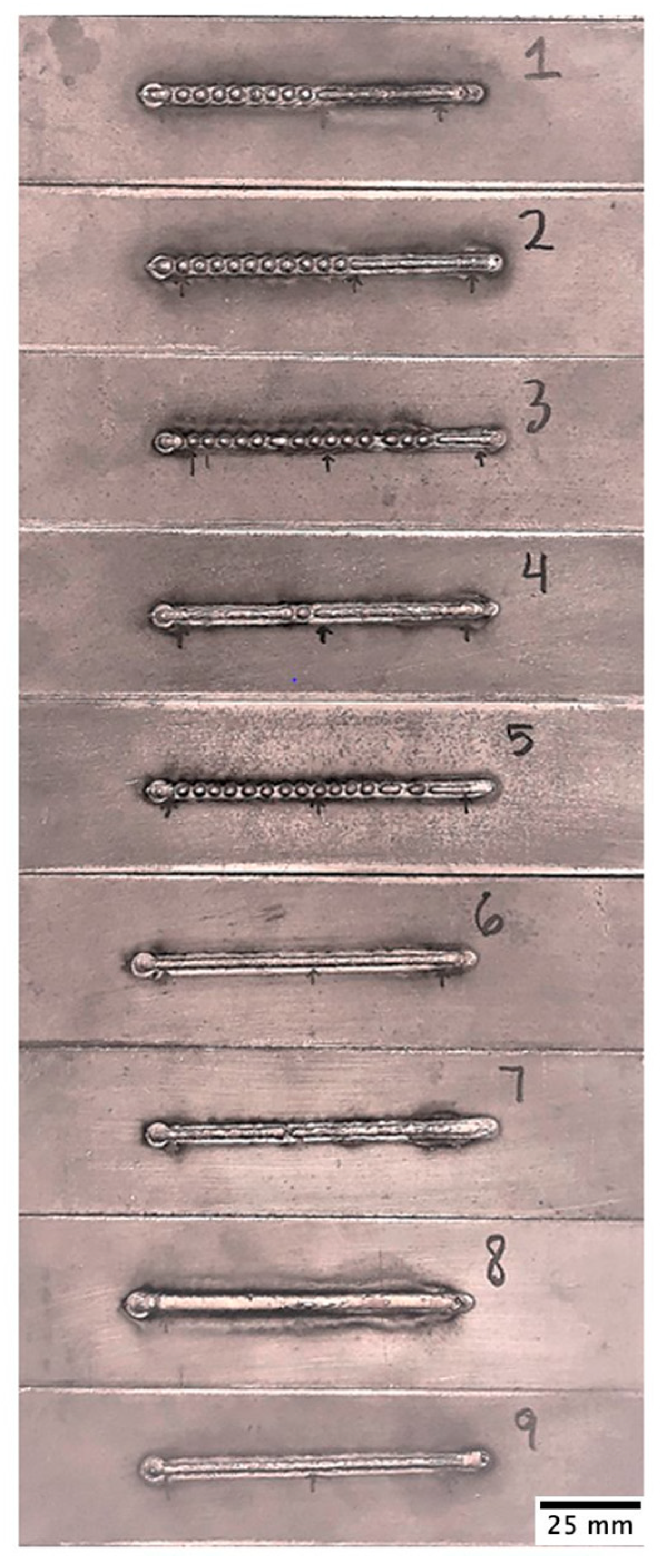
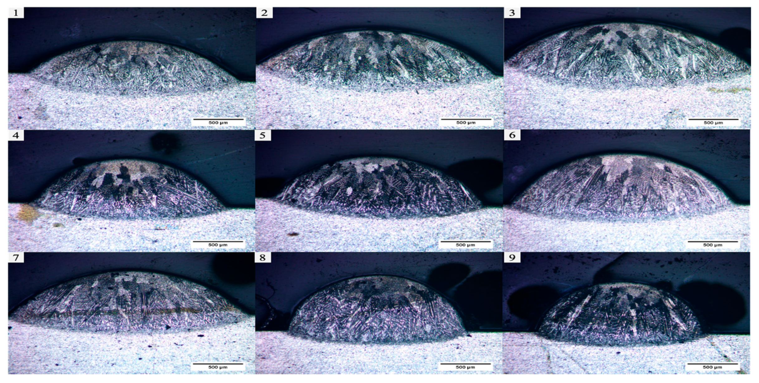
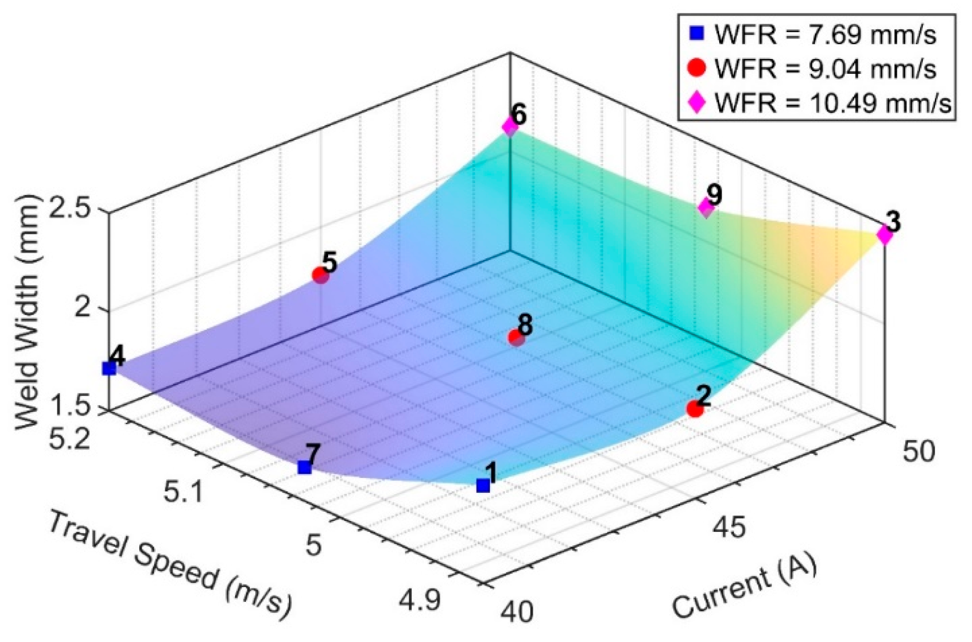
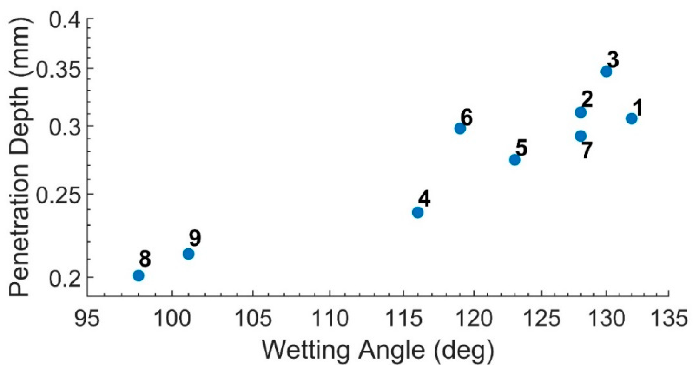
Table 5. Processing parameters and weld bead characteristics for Inconel 718 single pass samples.
Parameter Set #Current (A)Wire Feed Rate (mm/s)Travel Speed (mm/s)Weld Height (mm)Weld Width (mm)Penetration Depth (mm)Wetting Angle (Degrees)
1407.694.880.7931.9930.306132
2459.044.880.8071.9530.311128
35010.494.880.7652.450.347130
4407.695.20.7431.7130.238116
5459.045.20.8731.7570.274123
65010.495.20.7932.1230.298119
7407.695.030.9051.670.292128
8459.045.030.9451.8970.20198
95010.495.030.8152.170.213101
Publisher’s Note: MDPI stays neutral with regard to jurisdictional claims in published maps and institutional affiliations.

