Article

Effect of Rotation Speed and Steel Microstructure on Joint Formation in Friction Stir Spot Welding of Al Alloy to DP Steel

by
Hadi Torkamani
1,*,
Javier Vivas Méndez
2,*,
Clement Lecart
1,
Egoitz Aldanondo Begiristain
2,
Pedro Alvarez Moro
2 and
Marta-Lena Antti
1
1
Division of Materials Science, Luleå University of Technology, 97187 Luleå, Sweden
2
LORTEK Technological Centre, Basque Research and Technology Alliance (BRTA), Arranomendia kalea 4A, 20240 Ordizia, Spain
*
Authors to whom correspondence should be addressed.
J. Manuf. Mater. Process. 2022, 6(1), 24; https://doi.org/10.3390/jmmp6010024
Submission received: 17 January 2022 / Revised: 11 February 2022 / Accepted: 13 February 2022 / Published: 15 February 2022
(This article belongs to the Special Issue Frontiers in Friction Stir Welding and Processing)

Abstract

:
In this work, friction stir spot welding of 5754 aluminum alloy to dual phase steel was investigated using two different ratios of martensite and ferrite (0.38 and 0.61) for steel sheet initial microstructure and varying tool rotation speed (800, 1200 and 2000 rpm). The effect of these parameters on the joint formation was evaluated by studying the plunging force response during the process and the main characteristics of the joint at (i) macrolevel, i.e., hook morphology and bond width, and (ii) microlevel, i.e., steel hook and sheet microstructure and intermetallic compounds. The plunging force was reduced by increased tool rotation speed while there was no significant effect from the initial steel microstructure ratio of martensite and ferrite on the plunging force. The macrostructural characterization of the joints showed that the hook morphology and bond width were affected by the steel sheet initial microstructures as well as by the tool rotation speed and by the material flow driver; tool pin or shoulder. At microstructural level, a progressive variation in the ratio of martensite and ferrite was observed for the steel hook and sheet microstructure. The zones closer to the tool presented a fully martensitic microstructure while the zones away from the tool showed a gradual increase in the ferrite amount until reaching the ratio of ferrite and martensite of the steel sheet initial microstructure. Different types of FexAly intermetallic compounds were found in three zones of the joint; the hook tips, in the hooks close to the exit hole and in the corner of the exit hole. These compounds were characterized by a brittle behavior with hardness values varying from 456 to 937 HV01.

1. Introduction

The growing concerns surrounding energy saving and environmental conservation have increased the demand for lightweight structures. For instance, in the automobile field, lightweight structures enable a significant reduction in CO2 emissions [1,2]. Weight reduction while assuring crashworthiness in vehicles is highly unlikely without the use of multi-material structures [3]. Most of the investigated multi-material structures for the automotive industry are made with the combination of aluminum and steel. For this reason, being able to join different materials has become a crucial industrial asset [4].
Conventional welding techniques, which use fusion to join materials, reach a limit when dissimilar materials are to be welded due to the differences in the mechanical and physical properties of the materials to weld and the formation of brittle intermetallic compounds. Regarding aluminum–steel joints, the large difference between the melting temperature of steels and Al alloys and the formation of FexAly intermetallic compounds are the main reasons for limiting their use [5].
The uncontrolled formation and growth of FexAly intermetallic compounds (IMC) occurring in conventional welding techniques make them not recommended for use. In fact, the high generated heat input promotes the development of thick and brittle IMC, forming a layer between the steel and the aluminum [6]. Even though this layer has been reported to result in achieving strong welds, an excessive thickness would weaken the strength of the bond, as the brittle IMC favors the initiation and propagation of cracks [7]. An alternative to conventional welding techniques which is environmentally friendlier and has demonstrated its potential to join different materials [8,9,10], and more concretely aluminum to steel [11,12,13,14], is friction stir spot welding (FSSW).
FSSW is a solid-state, hot-shear process characterized by using a relatively low heat input to join the materials in comparison with the conventional welding techniques. FSSW consists of a cylindrical rotating tool that plunges at a specific rate into the overlapping sheets to a desired depth. The tool is retracted at a rate either immediately or after a dwell period. The frictional heat generated by the rotating tool softens the material causing material flow in the circumferential and axial directions. The force applied by the tool results in the formation of an annular ring shaped solid state joint and the retraction of the tool leaves a characteristic exit hole.
The main FSSW parameters are tool rotation speed, plunge rate, plunge depth and dwell time. Although FSSW has been widely investigated [15,16,17,18,19] and is already used in industrial production [20,21], information on how these parameters affect joint formation is still limited.
S. Lathabai et al. [22] investigated the relevance of plunge rate and plunge depth on bond formation and tensile shear strength and concluded that plunge depth had the greatest influence on the tensile shear strength of the joints. Tozaki et al. [23] studied the effect of processing parameters on the static strength of dissimilar friction stir spot welds between different aluminum alloys showing that rotation speed and dwell time have a great impact on this property. Shen et al. [24] also investigated the effects of rotation speed and dwell time on the microstructure and mechanical properties of friction stir spot welds in 2.0 mm-thick AA6061-T4 aluminum alloy, highlighting the importance of these parameters to obtain defect-free joints with proper mechanical behavior.
Focusing on FSSWed Al-steel joints, there is a lack of knowledge regarding the effect of the steel sheet microstructure and some important FSSW parameters, such as rotation speed, on the dissimilar Al-steel joint characteristics.
A promising material combination for multi-material structures is dual-phase (DP) steels and aluminum alloys. DP steels are known to possess a good combination of mechanical properties such as strength and ductility [25,26]. To obtain DP microstructures, intercritical heat treatment (IHT) is a successful practical process applied mostly on low-carbon low-alloyed steels [27]. This treatment consists of heating such a steel alloy within the intercritical temperature range followed by quenching. The intercritical temperature range is defined by the temperatures between the onset of austenitization (Ac1) and the temperature corresponding to the completion of austenitization (Ac3). Heating a steel in this area for some times establishes an austenite and ferrite microstructure in the intercritical region. The quenching process (i.e., cooling rate and temperature) determines if the austenite (coexisting with ferrite) is transferred either into bainite or martensite as explained in [25], resulting in ferritic-bainitic or ferritic-martensitic DP microstructures, respectively. The choice of the temperature used for intercritical heat treatment is important, since raising the IHT temperature would increase the volume fraction of austenite, transformed into martensite after quenching. However, employing higher IHT temperatures, the strength and hardness of this transformed martensite would be lower as the carbon content of the parent austenite has been lower. This effect has been reported in a previous work of some of the authors [28], where, by decreasing the IHT temperature from 800 to 750 °C, the volume fraction of martensite decreased from 0.68 to 0.36. At the same time, the amount of carbon in austenite increased from 0.24 to 0.44 wt%. In that work, it is also discussed how employing higher IHT temperature would result in higher yield (YS) and ultimate tensile strengths (UTS).
In this work, the effect of tool rotation speed and initial DP steel microstructure on joint formation in FSSW of DP steel to aluminum alloy is investigated. For this purpose, tailored DP steel microstructures with different ratios of martensite and ferrite have been designed and several friction stir spot welded joints have been performed by varying the tool rotation speed. The characterization of the joints has been focused on the main characteristics, the hook morphology, the annular ring shape bond and the nature and location of the intermetallic compounds.

2. Materials and Experimental Procedures

2.1. Materials

The base materials used in this work were 2 ± 0.2 mm thick sheets of AA5754-H111 and 3 mm thick sheets of low-carbon steel, which is a commercially available product (Strenx 960) from SSAB company. The chemical compositions of the alloys are given in Table 1 and Table 2.

2.2. Design and Fabrication of Tailored DP Steel Microstructures

To obtain the desired dual-phase microstructure for the steel samples, an intercritical heat treatment had to be designed. For this reason, a dilatometry experiment was performed on the steel using a Netzsch DIL402C dilatometer. A slow heating ramp of 0.05 °C/s followed by a 600 s holding time at 900 °C were applied to the steel to obtain a condition as close as possible to equilibrium [29]. In addition to dilatometry, ThermoCalc software version 2021b along with the TCFE11 database helped to foresee the austenite fraction and its carbon content within the intercritical region. Two IHT temperatures were chosen based on the values of critical temperatures obtained from dilatometry and ThermoCalc results. Having chosen the IHT temperatures, the designed heat treatment cycles were performed in a NABERTHERM muffle furnace, including heating and holding the samples at the targeted IHT temperatures for 30 min, followed by water quenching. The aim of the heat treatment cycles was to obtain two different ferritic-martensitic DP microstructures.

2.3. Friction Stir Spot Welding

To produce the FSSW joints, aluminum alloy and steel sheets were cut and machined into regular welding samples, 30 mm long by 30 mm wide. The sheets were clamped in a lap configuration, where the Al sheet was placed on top.
All the joints were carried out in a commercially available friction stir welding machine (I-STIR PDS 4) with a tilt angle of 0° using position control mode. The FSSW joints were obtained by employing a fixed plunge rate, depth and pin length and varying the tool rotation speed. Table 3 summarizes the FSSW parameters used. It is worth mentioning that each test (with the given FSSW parameters) was repeated three times and was prepared for further analyses such as microstructural examination and hardness measurements.
During FSSW, the plunging force was measured by high accurate pressure cells. The FSSW tool used consisted of a 4 mm diameter cylindrical pin with a curved edge (3 mm in diameter of the flat contact area) made of WC-Co alloy and a flat 12 mm diameter shoulder made of M42 steel (Figure 1).

2.4. Sample Preparation for Metallographic Observations and Microhardness Measurements

After welding, joints were cut by the center for metallographic observations. Standard grinding and polishing procedures were followed to prepare the samples, and a Nital reagent was used to reveal the steel microstructure. In dissimilar joints, the different etching tendency of different alloys (Al and steel alloys, in this case) is a convenient and practical way to reveal the pattern of the intermixed regions between two sheets and of the material flow caused by the rotating tool [9].
In order to measure the volume fraction of the phases present in the heat-treated samples, scanning electron microscope (SEM, JEOL SEM JSM-IT300) images were processed by an image analyzer software (ImageJ).
Optical microscopy (OM, Nikon Eclipse MA200) was employed to provide proper observation of different areas in the joints. To characterize the microstructure of the heat treated (i.e., IHT) samples, images with higher magnification were taken by SEM. The SEM was equipped with an energy dispersive spectroscope (EDS) to perform the microanalyses on the key spots.
The sectioned parts of the joints were used for Vickers microhardness measurements. All specimens were ground and polished before performing the microhardness profiles across the steel thickness and on the phases of interest.
Microhardness measurements were performed using a Matsuzawa hardness tester equipped with Buehler Omnimet hardness measurement system and a diamond Vickers indenter. The dwell time was kept to 15 s for all the indents. To measure the hardness of the steel with either martensitic or DP microstructures, a load of 200 g was used, while for the other phases of interest (e.g., intermetallic compounds), lower load (100 g) was employed in order to reduce the size of the indents.

3. Results and Discussion

3.1. Design of Heat Treatments to Produce Tailored DP Steel Microstructures

As mentioned in Section 2.2, IHT cycles were designed according to the results obtained from the dilatometry test. Figure 2 shows the results of the dilatometry test intended to determine the intercritical region for the studied steel by measuring the critical temperatures (Ac1 and Ac3). According to Figure 2a, during the slow heating (0.05 °C/s), the initial microstructure expands linearly up to Ac1 where the first contraction is observed. It corresponds to the transformation of pearlite into austenite. The change recorded is the onset of austenitization. This transformation is followed by a slower (second) contraction that can be noticed on the dilatometry graph, which is due to the transformation of ferrite into austenite. To consolidate these Ac1 and Ac3 estimations, the derivative of the relative change in length as a function of temperature has been plotted during the continuous heating up to 900°C (Figure 2b). The results obtained give Ac1 = 715 °C and Ac3 = 863 °C. These two temperatures delimited the intercritical region for the studied steel.
ThermoCalc software was used to predict the volume fraction and carbon content of austenite as a function of temperature in the intercritical region. Figure 3 shows the results of ThermoCalc corresponding to the low-carbon steel used in this study. Comparing the results obtained from dilatometry (Figure 2) and ThermoCalc (Figure 3), one can realize that there is a difference between the critical temperatures measured based on experimental results (dilatometry) and the ThermoCalc prediction. The difference is mainly raised from the fact that ThermoCalc deals with the equilibrium condition, while even heating rates as slow as 0.05 °C/s in the dilatometry system are not sufficiently slow to reach the equilibrium condition: this can also be somehow the case when performing the heat treatment cycles. Despite the differences, ThermoCalc still gives valuable insights in terms of the volume fraction of the phases and the carbon content of austenite in intercritical regions, which can be used to support the explanations of the phenomena taking place in the steel parts. The next step in designing the IHT was choosing two temperatures that would create two different microstructures after quenching.
According to the results of the dilatometry test, two temperatures, 725 and 775 °C were chosen to perform the intercritical heat treatments.

3.2. Characterization of Tailored DP Steel Microstructures

The volume fraction of phases in the DP steels was estimated from SEM images taken from the intercritically heat-treated samples. Figure 4a,b present two different microstructures obtained after applying the IHT at 725 and 775 °C, respectively. Figure 4c,d demonstrate the processed images, suggesting a lower volume fraction of martensite (Vm) for the steel treated at a lower IHT temperature. The results of the image analyses gave an average value of Vm = 0.38 for IHT725 and Vm = 0.61 for IHT775 samples: in this work, these denominations, IHT725 and IHT775, are used for the steel samples heat treated at 725 and 775 °C, respectively.
Hardness measurements were carried out for the heat-treated steel samples. As expected, the sample heat treated at 725 °C had a lower hardness (327 HV) than the IHT775 sample (377 HV). The obtained hardness values make sense, knowing that the microstructure of IHT775 contains almost twice as much martensite as IHT725, though the hardness of martensite in the latter case would be feasibly higher (because of higher carbon content, Figure 3).
For ease of reading, considering the developed DP steel microstructures and the rotation speeds studied, Table 4 summarizes the terminologies for the different conditions, which will be used hereafter in this work.

3.3. Plunging Force Response during FSSW

Figure 5 shows the variation in plunging force developed during FSSW as a function of time for rotation speeds of 800, 1200 and 2000 rpm. As seen in this figure, the variation in plunging force with time showed a similar trend for all three rotation speeds, although its magnitude was reduced significantly with increased rotation speed. For each speed, the plunging force initially increased rapidly for a very short period of time and then more slowly until reaching a plateau. After that, plunging force increased quickly when the tool pin made contact with the DP steel. As the shoulder made contact with the specimen surface, the force increased further to a peak value and then dropped gradually until the tool was retracted. The peak force decreased from 16–17 kN at 800 rpm to 10–11 kN at 2000 rpm. Note that higher plunging forces are generated for lower rotation speeds, which could have an adverse effect on tool life.
The analysis of the plunging force–time curves provides valuable information about the processes of thermally activated softening, strain and strain rate hardening and deformation that occur during FSSW. It is known that the yield stress of materials is highly temperature dependent. On the other hand, higher rotation speeds produce higher frictional heat and greater thermally activated softening which result in lower plunging forces. In fact, there is an upper limit in friction stress/plunging force, which cannot exceed the shear flow stress of the workpiece; as soon as the friction shear stress reaches this level, shearing in a layer below the tool surface will dominate. Therefore, the higher plunging forces at lower rotation speeds are associated with reduced temperatures during FSSW and a higher strain hardening response.
Figure 6 represents the effect of the steel microstructure on the plunging force. In these experiments, the rotation speed was held constant. As can be seen in the curves, no important effect on the plunging force was observed due to the steel microstructure. As stated above, plunging force involves mainly the force/stress required to shear a layer of materials around the tool. During the FSSW process, the temperature of the regarded layer goes up, probably reaching the austenitization temperature in the surface of the steel sheet. Therefore, the initial microstructure would decompose due to the heating process; the microstructural evolutions in the steel parts will be further discussed in the next subsection. Moreover, since the steel samples have identical chemical composition in all conditions (even with different initial microstructures), the shear flow stress of the material (close to the tool) would feasibly be the same, when the same rotation speed has been employed. This might explain the reason why the initial microstructure has almost no effect on the plunging force.

3.4. Characterization of the Joints

3.4.1. Macrostructural Characterization: Hook Morphology and Bond Width

Figure 7 depicts low magnification views of cross sections of the FSSW joints produced with different rotation speeds and DP steel microstructures. All joints were well-formed due to sufficient heat input and material flow during the process. The hook, a quite common characteristic in friction stir welded lap joints [30,31,32], could be observed in all conditions. The hook is formed by the penetration of the steel into the aluminum. It is originated by the severe material flow along the vertical direction during the FSSW. The hook facilitates the interlocking between aluminum and steel sheets, thus, strongly affecting the mechanical behavior of the joint. The figure shows how different rotation speeds affect the initial microstructure of the steel sheet (around and beneath the exit hole) and the hook area. There are some regions with different contrast (almost white) appearing around the hooks and in the corner of the exit hole. The size and shape of these areas are also affected by the variations.
It can be apprehended from Figure 7 that the rotation speed and DP steel microstructure affect material flow pattern, which modifies the morphology of the hook. In this section, the main characteristics of the hook (hook height, width and its bond width) have been measured to evaluate the effect of the regarded parameters on the hook morphology.
Figure 8 shows the hook height and width of the investigated joints as a function of the rotation speed and DP steel microstructure. From Figure 8a, it can be seen that at the lowest speed (800 rpm), hook height was quite similar for both steel microstructures, while at the higher speeds, hook height was higher for IHT775 than that for IHT725 sample. This may be attributed to enhanced material upward flow induced by the steel microstructure. DP steel microstructures with higher content of martensite promote a more pronounced vertical material flow which results in a more severe displacement of the steel sheet into the aluminum sheet. When rotation speed increases, the hook height first increases and then decreases for both DP steel microstructures. One possible reason for this behavior may be a change in the material flow driver from pin to shoulder or vice versa. This phenomenon has been observed and discussed elsewhere [33].
In Figure 8b, the variation of hook width with rotation speed and steel microstructure are depicted. The hook widths were longer for IHT725 than for IHT775 when employing the low rotation speeds (800 and 1200 rpm), while at the highest rotation speed (2000 rpm), IHT775 exhibited a longer hook width. Based on material flow patterns, it seems that at the lowest rotation speed, microstructures with a higher content of ferrite are more prone to flow towards the sides than those with a lower content of ferrite. However, at the highest rotation speed, this trend changes. When rotation speed increased from 800 to 1200 rpm, no significant difference in the hook width was observed for the different steel microstructures. On the other hand, increasing the rotation speed to 2000 rpm, IHT775 faced an increase in the hook width while this parameter decreased for IHT725. As mentioned previously, this behavior may be explained by a change in the material flow driver.
Figure 9a shows the variation of the bond width as a function of rotation speed and steel microstructure. One should note that the bond width is considered as the loss of top and bottom sheet interfaces, forming a perfect bond due to stirring (Figure 9b). At the lowest rotation speeds, the bond width was almost the same for both steel microstructures, but at the highest rotation speed the bond width was considerably higher for IHT725 than that for IHT775.
Rotation speed did not seem to have any remarkable impact on the bond width up to 1200 rpm for both steel microstructures. However, at the highest speed the bond width experienced a great increase for IHT725 and IHT775, being more pronounced for IHT725. This increment is due to the increase in frictional heat and the expansion of the stirred interface zone. The bonded width itself comprises three different parts: (i) the stir zone width, (ii) the width of lower sheet material displaced upwards during the welding operation, and (iii) the width of the partially bonded region. This was defined earlier by Y.H. Yin et al. [34]. This bonding is built based on the contribution of the different parts, which is significantly affected by rotation speed and initial microstructure, especially at a rotation speed as high as 2000 rpm (Figure 9a).

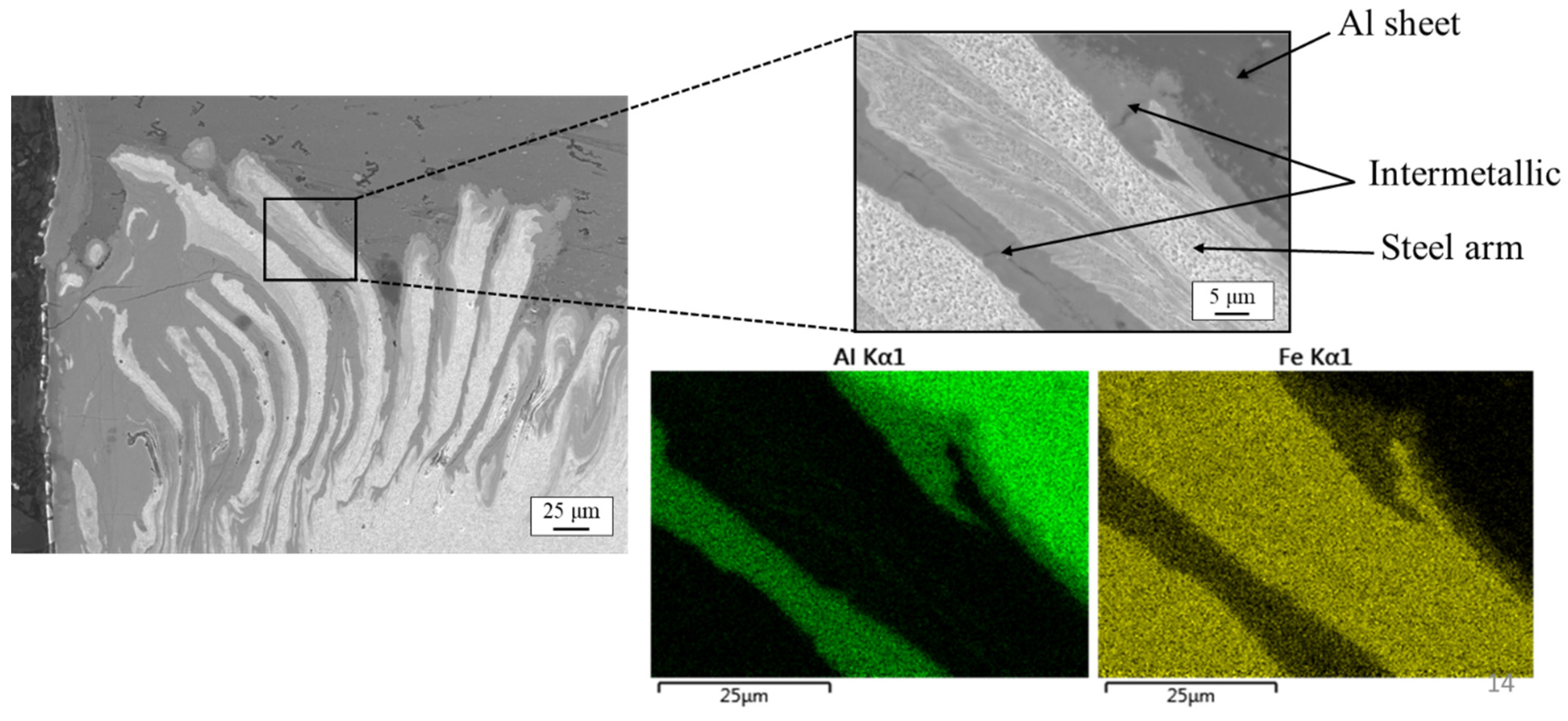
3.4.2. Microstructural Characterization: Steel Hook and Sheet Microstructures and Intermetallic Compounds

Figure 10a,c show the left and right hooks formed in the T775S12 sample, respectively. In these images, areas with different contrast can be recognized, especially within the hook arms and in the corner of the exit hole. Figure 10b displays the presence of different zones in the area just below the exit hole. In this figure, as well as in Figure 10a,c, different zones can be distinguished thanks to the contrast variations. According to the literature, these zones are the stir zone (SZ, just below the exit hole), the thermomechanically affected zone (TMAZ), and the heat-affected zone (HAZ) [35]. The formation of these zones are due to the heat input, forces and material flow generated during FSSW [36]. These areas are further discussed in the following subsections.
Figure 10 suggests different zones formed below the exit hole area. Microscopic characterizations by SEM are provided to better understand the influence of changes in the steel initial microstructure or of varying the process parameters (i.e., rotation speed) on the microstructure of the steel sheet. Figure 11 shows the area of interest in the T725S08 sample. The magnified images in this figure provide closer observation of the microstructure from the surface to the inner part of the steel sheet. It is worth mentioning that it is a difficult task to measure the temperature distribution within the weld, particularly within SZ, due to the severe plastic deformation produced by the tool. From Figure 11, it can be deduced that the microstructure close to the surface (pin contact) contains a martensite fraction much higher than in the intercritically heat-treated steel (with Vm = 0.38). This is due to the high heat input and elevated temperature in this area, reaching to the austenitization temperature. Once the pin is retracted, this area undergoes a rapid cooling stage, resulting in the formation of martensite. The heating cycle and the cooling involved in the FSSW process might result in different microstructures from the surface (in contact with the pin) to the inner part of the steel. It is worth mentioning that the microstructural evolution might vary in different steel alloys due to their varying chemical composition and thus hardenability [37]. Accordingly, the region away from the tool pin may experience other heating cycles or deformation mechanisms, since the temperatures and strain rates would decrease towards the base material. For instance, next to SZ, there exists TMAZ, which experiences less deformation (stirring) and heat. This can be realized from the fraction of martensite in TMAZ (Figure 11). It seems that the material in this region has not reached the full austenitization temperature. However, the temperature has still been higher than the temperature employed for intercritical heat treatment as its martensite fraction is still higher than the base steel sheet. Finally, moving towards the base steel sheet, one can find the microstructure similar to the initial IHT steel sample. From Figure 11, it can be realized that there is no clear boundary between these areas and the transition between the zones and that microstructure changes (in terms of the fraction of the phases) occur gradually from the surface to the inner part of the steel.
Microhardness profiles under the pin contact area were plotted in order to determine the influence of heat and deformation gradients on the steel hardness. Figure 12a shows the area through which the microhardness measurements were made. The effect of rotation speed on the hardness of IHT725 and IHT775 samples (the steel part) is shown in Figure 12b,c, respectively. Figure 12d compares the effect of initial microstructure (different Vm) on the hardness profile, when subjected to the same rotation speed (1200 rpm).
Comparing Figure 12b with Figure 12c, it is clear that the changes in hardness values in the SZ and TMAZ follow an almost similar trend in both IHT725 and IHT775 samples. Close to the surface, high values of hardness are obtained corresponding to the SZ where a fully martensitic microstructure is observed (Figure 11). The hardness values are also an indication of the deformation due to the forces exerted by the rotating tool. A first value obtained close to the exit hole is slightly lower than the next few values. This might be due to the effect of free surface as the indent has been made very close to the exit hole. These hardness values concern the area where full recrystallization of austenite grains has occurred followed by martensitic transformation. Previous studies [38,39] suggested that fine equiaxial grains form in SZ owing to dynamic recrystallization (DRX) since SZ experiences elevated temperature and a large degree of plastic deformation during the welding process. Chen et al. [40] found that the grain size (within SZ) decreases with the decreasing rotation speed due to the corresponding lower heat input. It can be concluded that the hardness values obtained within SZ can be interpreted by the fact that employing higher rotation speeds would result in both larger heat input (higher peak temperature), and higher strain rate (more intense deformation) [41], which act in an opposing way to determine the hardness.
A slight decrease in hardness level was noticed when entering the TMAZ, where there was a gradually increasing impact of the heat gradient and deformation on lowering the hardness. The hardness dropped to a minimum value towards the inner part of the steel sheet. This part would feasibly correspond to the HAZ in which the impact of the heat input and deformation is progressively decreasing. It is worth mentioning that the hardness values obtained in different zones, especially in HAZ, are not only affected by the fraction of martensite but also by tempering of the existing martensite (from the initial DP microstructure). Even though the temperature did not reach Ac1 temperature, it could still be high enough to temper the martensite in the DP microstructures, decreasing the hardness of the steel, which is mainly the case of HAZ.
After HAZ, the hardness would be expected to slightly increase until reaching the plateau (i.e., the hardness of the base material). In fact, this area was followed by a slow increase in the hardness level, reaching almost the hardness of the heat treated steel with the initial DP microstructure (Figure 12b–d). The hardness of the initial DP microstructure (base materials) itself could be affected by the heating cycle during the FSSW process.
Considering the effect of rotation speed on the width of these areas, it can be apprehended from Figure 12b,c that increasing the rotation speed would widen the stir+thermomechanical affected zones (SZ+TMAZ). It makes sense since strain rate and heat input are more intense in the case of faster rotation speeds; the zone transition occurs with delay.
According to what has been stated, the hardness of SZ is affected by rotation speed rather than by the initial microstructure. This is also the case for the width of the different zones, which is controlled by rotation speed. This scenario can be better understood when comparing two conditions with a given rotation speed, as presented in Figure 12d. It can be deduced from this figure that the hardness of SZ is the same for both IHT725 and HIT775 samples while the hardness in HAZ, and especially in the base material, is different, reaching almost the hardness of base/initial microstructures.
Figure 10a and c depicted a general view of the hooks formed in the joints. The SEM images provided in Figure 13 illustrate the morphology of the hooks formed in samples intercritically heat treated at 775 °C and then FSSWed under different rotation speeds. As commented in Figure 10, different areas can be distinguished in the hook according to their grain structure. They are SZ, TMAZ and HAZ. Similar hook morphology has been reported previously by [42] who named these areas within the hooks as chip layer (HAZ), elongation layer (TMAZ), and recrystallization layer (SZ). The phase transformations and evolutions that occur in these areas are the same as those explained previously for the steel sheet. The magnified image in Figure 13c provides a clearer picture of the hook. As noticed in Figure 10, this magnified image also suggests different contrasts between some areas. This might be due to formation of different phases (e.g., IMC layers) around or within the hook.
EDS microanalyses were carried out in order to characterize the phases developing in the hooks and near the exit hole. Figure 14 shows the results of elemental mapping microanalyses performed on a part of the hook formed in the T725S08 sample. This mapping allowed the distinguishing of the base materials (aluminum alloy and DP steel sheets) from their cooperative products, as the amount of Fe and Al varies significantly from each phase to another. Between the Al alloy and steel arms, there exist regions rich in both Al and Fe, suggesting the formation of intermetallic compounds. These regions are indicated in Figure 14. Based on these dissimilar joints where the softer material is the upper sheet, the formation of IMCs at different areas would be due to both downward flow of the soft material and upward and outward flow of the hard material [43].
The results of line scanning EDS microanalyses (Figure 15) confirmed the existence of IMC particles/layers, as both Fe and Al coexisted in some areas within the arms, co-operating in the formation of IMC. In other words, the analyzed area includes layers of steels arms and IMC. Now, one can suggest that the phases/areas with different contrasts, noticed in Figure 10 and Figure 13, belong to the base materials as well as to the IMC layers.
Closer observation and further characterization of the IMC layers has been carried out by SEM and point EDS microanalyses. Figure 16 shows a part of the hook close to the exit hole. In the SEM image, the steel arms and IMC layers can be recognized, while there is also a contrast between the IMCs. The EDS results obtained from the area close to the exit hole (Table 5), in addition to existence of base Al and steel alloys, highlight the different types of intermetallic compounds formed within the arms. As shown in this figure, spectra have been measured in several locations, at a distance between 20 µm and 220 µm from the exit hole interface. Spectrum 1 and spectrum 2 correspond to the base materials with high Al and Fe contents (Table 5), identifying the Al and steel sheets, respectively. The other three spectra show the development of two different types of IMCs. It can be realized that spectra 3 and 5 accommodate more Al compared to spectrum 4. This could be due to the different types of IMC that have been formed in different regions and this complies with [44,45] which reported that Al2Fe3, FeAl2 or Fe3Al5 were developed in dissimilar Al-steel FSSWed joints. Figure 16 shows shade variations between these IMCs and close to the exit hole interface (Spectrum 4), the IMC layer is brighter than the one separating within or close to the steel arms (Spectra 3 and 5). These IMCs will be further characterized by hardness measurements, below.
OM images provided in Figure 10a,c show a sectioned view of the hooks on both sides of the joint, in T775S12 sample. In addition to the parts that have been described so far (steel sheet and hook areas), a bright phase appears in the corner of the exit hole. Figure 17 shows an SEM image of the corner of the exit hole area (left part) together with the results of elemental mapping performed on the selected area. According to this figure, the bright phase noticed in this area (Figure 10) is identified as IMC, since it accommodates both Al and Fe. It can be seen in this figure that a crack has been generated in the IMC, implying the brittle behavior of such compounds. In most of the cases, this part is connected to the IMCs formed in the vertical interface between the exit hole and the steel sheet, which has been analyzed in Figure 16. The macro observation of the joints in Figure 7 also suggests that the formation and size of this IMC (in the corner of the exit hole) is mainly affected by rotation speed, where the initial microstructure (fraction of martensite) might also have an effect.
Figure 18 illustrates the reconstructed OM images corresponding to IMCs that have formed in the interface and corner of the exit hole in the T725S12 sample. The magnified images show the indents and the results of microhardness measurements performed on the IMCs; the numbers reported in this figure give the value of hardness in HV. The results of EDS microanalyses suggested the formation of different types of IMCs (with different contrasts). One should bear in mind that the contrast between the phases might change when using SEM or OM. When comparing the same area, the IMCs that appear with darker contrast in the SEM image (Figure 16) might appear as a brighter phase in OM images (Figure 18). According to Figure 18, it seems that the IMCs closer to the exit hole possess higher hardness than IMCs at further distance from the hole. The different hardness values are attributed to the type/stoichiometry of the IMC, involving Al and Fe. These IMCs have various crystal structures [46,47] and offer a wide range of hardness levels [48]. Further investigations might be required to thoroughly understand the effect of rotation speed or the initial steel microstructure on the type of IMCs formed.

4. Conclusions

In this work, the effect of rotation speed and martensite to ferrite ratio of the initial DP steel microstructure on joint formation in FSSW of aluminum alloy to DP steel has been investigated. To do that, the plunging force response during FSSW has been analyzed, the main characteristics of the joint have been studied and the microstructure of the DP steel sheet has been characterized before and after welding. The main conclusions that can be drawn are:
  • Two intercritical heat treatments were designed according to dilatometry results and applied to establish DP microstructures with different ratios of martensite and ferrite. Performing intercritical heat treatment at 725 and 775 °C results in Vm = 0.38 and 0.61, respectively.
  • Increasing rotation speed generates higher frictional heat and consequently material softening. Therefore, the increase of rotation speed also comes with a reduction of the plunging force. However, the ratio of martensite and ferrite in the initial DP steel microstructure does not have an important effect on the plunging force.
  • Initial DP steel microstructure affects hook height and width due to the different abilities to flow for ferrite and martensite. However, hook morphology also depends on rotation speed and material flow driver (pin or shoulder).
  • Bond width is affected by rotation speed and ratio of martensite and ferrite in the DP steel microstructure but only when the rotation speed is high enough; in this work at 2000 rpm. The increase of the bond width at high rotation speed is caused by the increase of frictional heat and the expansion of the stirred interface zone.
  • A fully martensitic microstructure was obtained in the steel sheet, just beneath the exit hole, suggesting that the temperature in the regarded area has reached the austenitization temperature during the FSSW process. The fraction of martensite decreases towards the base material, reaching Vm of the initial DP microstructure. This microstructural evolution could be accompanied with both softening (e.g., dynamic recrystallization and tempering) and hardening (e.g., work hardening) phenomena, resulting in different hardness values within the analyzed areas (i.e., SZ, TMAZ, and HAZ).
  • Different types of FexAly intermetallics are formed in three zones of the joint; the hook tips, in the hooks close to the exit hole and in the corner of the exit hole. These intermetallics are brittle and their hardness values vary from 456 to 937 HV01.

Author Contributions

Conceptualization, H.T. and J.V.M.; investigation, H.T., J.V.M. and C.L.; methodology, C.L.; supervision, H.T., J.V.M., E.A.B., P.A.M. and M.-L.A.; writing—original draft, C.L.; writing—review and editing, H.T., J.V.M. and M.-L.A. All authors have read and agreed to the published version of the manuscript.

Funding

This project received funding from the European Union’s Marie Skodowska-Curie Actions (MSCA) Innovative Training Networks (ITN) H2020-MSCA-ITN-2017 under the grant agreement No. 764979. The research was partially funded by the Kempe foundations (a research fund, received by Luleå University of Technology).

Data Availability Statement

The authors confirm that the data supporting the findings of this study are available within the article.

Acknowledgments

Erik Nilsson and Lars Frisk from materials group (at Luleå University of Technology) and Imanol Aldazabal from LORTEK are acknowledged for their experimental support.

Conflicts of Interest

The authors declare no conflict of interest.

References

  1. Meschut, G.; Janzen, V.; Olfermann, T. Innovative and Highly Productive Joining Technologies for Multi-Material Lightweight Car Body Structures. J. Mater. Eng Perform. 2014, 23, 1515–1523. [Google Scholar] [CrossRef]
  2. Tisza, M.; Czinege, I. Comparative Study of the Application of Steels and Aluminium in Lightweight Production of Automotive Parts. Int. J. Lightweight Mater. Manuf. 2018, 1, 229–238. [Google Scholar] [CrossRef]
  3. Goede, M.; Stehlin, M.; Rafflenbeul, L.; Kopp, G.; Beeh, E. Super Light Car—Lightweight Construction Thanks to a Multi-Material Design and Function Integration. Eur. Transp. Res. Rev. 2009, 1, 5–10. [Google Scholar] [CrossRef] [Green Version]
  4. Tatsuya, S.; Gen, M.; Yasuaki, N.; Kenji, S.; Yasunobu, M.; Hatsuhiko, O.; Tetsuro, N. Dissimilar Metal Joining Technologies for Steel Sheet and Aluminum Alloy Sheet in Auto Body. Nippon Steel Tech. Rep. 2012, 103, 91–98. [Google Scholar]
  5. Shah, L.H.; Ishak, M. Review of Research Progress on Aluminum–Steel Dissimilar Welding. Mater. Manuf. Processes 2014, 29, 928–933. [Google Scholar] [CrossRef]
  6. Dilthey, U.; Stein, L. Multimaterial Car Body Design: Challenge for Welding and Joining. Sci. Technol. Weld. Join. 2006, 11, 135–142. [Google Scholar] [CrossRef]
  7. Tanaka, T.; Morishige, T.; Hirata, T. Comprehensive Analysis of Joint Strength for Dissimilar Friction Stir Welds of Mild Steel to Aluminum Alloys. Scr. Mater. 2009, 61, 756–759. [Google Scholar] [CrossRef]
  8. Haghshenas, M.; Gerlich, A.P. Joining of Automotive Sheet Materials by Friction-Based Welding Methods: A Review. Eng. Sci. Technol. Int. J. 2018, 21, 130–148. [Google Scholar] [CrossRef]
  9. Shen, Z.; Ding, Y.; Gerlich, A.P. Advances in Friction Stir Spot Welding. Crit. Rev. Solid State Mater. Sci. 2020, 45, 457–534. [Google Scholar] [CrossRef]
  10. Mohan, D.G.; Gopi, S.; Tomków, J.; Memon, S. Assessment of Corrosive Behaviour and Microstructure Characterization of Hybrid Friction Stir Welded Martensitic Stainless Steel. Adv. Mater. Sci. 2021, 21, 67–78. [Google Scholar] [CrossRef]
  11. Figner, G.; Vallant, R.; Weinberger, T.; Enzinger, N.; Schröttner, H.; Paśič, H. Friction Stir Spot Welds between Aluminium and Steel Automotive Sheets: Influence of Welding Parameters on Mechanical Properties and Microstructure. Weld. World 2009, 53, R13–R23. [Google Scholar] [CrossRef]
  12. Piccini, J.M.; Svoboda, H.G. Tool Geometry Optimization in Friction Stir Spot Welding of Al-Steel Joints. J. Manuf. Processes 2017, 26, 142–154. [Google Scholar] [CrossRef]
  13. Rong, Z.; Li, L.; Chen, L.; Yuan, H.; Zhu, S.; Sun, Y.; Guan, S. The Effect of Zn Coating Layer on the Microstructure and Mechanical Properties of Friction Stir Spot Welded Galvanized DP590 High-Strength Steel Plates. Int. J. Adv. Manuf. Technol. 2021, 113, 1787–1798. [Google Scholar] [CrossRef]
  14. da Silva, A.A.M.; Aldanondo, E.; Alvarez, P.; Arruti, E.; Echeverria, A. Friction Stir Spot Welding of AA 1050 Al Alloy and Hot Stamped Boron Steel (22MnB5). Sci. Technol. Weld. Join. 2010, 15, 682–687. [Google Scholar] [CrossRef]
  15. Su, P.; Gerlich, A.; North, T.H.; Bendzsak, G.J. Material Flow during Friction Stir Spot Welding. Sci. Technol. Weld. Join. 2006, 11, 61–71. [Google Scholar] [CrossRef]
  16. Yang, Q.; Mironov, S.; Sato, Y.S.; Okamoto, K. Material Flow during Friction Stir Spot Welding. Mater. Sci. Eng. A 2010, 527, 4389–4398. [Google Scholar] [CrossRef]
  17. El-Sayed, M.M.; Shash, A.Y.; Abd-Rabou, M.; ElSherbiny, M.G. Welding and Processing of Metallic Materials by Using Friction Stir Technique: A Review. J. Adv. Join. Processes 2021, 3, 100059. [Google Scholar] [CrossRef]
  18. Fujimoto, M.; Koga, S.; Abe, N.; Sato, S.Y.; Kokawa, H. Analysis of Plastic Flow of the Al Alloy Joint Produced by Friction Stir Spot Welding. Weld. Int. 2009, 23, 589–596. [Google Scholar] [CrossRef]
  19. Janeczek, A.; Tomków, J.; Fydrych, D. The Influence of Tool Shape and Process Parameters on the Mechanical Properties of AW-3004 Aluminium Alloy Friction Stir Welded Joints. Materials 2021, 14, 3244. [Google Scholar] [CrossRef]
  20. MAZDA NEWSROOM∣Mazda Develops World’s First Steel and Aluminum Joining Technology Using Friction Heat∣NEWS RELEASES. Available online: https://newsroom.mazda.com/en/publicity/release/2005/200506/050602.html (accessed on 22 September 2021).
  21. MAZDA:Backnumber|News Releases. Available online: https://newsroom.mazda.com/en/publicity/release/2003/200302/0227e.html (accessed on 22 September 2021).
  22. Lathabai, S.; Painter, M.J.; Cantin, G.M.D.; Tyagi, V.K. Friction Spot Joining of an Extruded Al–Mg–Si Alloy. Scr. Mater. 2006, 55, 899–902. [Google Scholar] [CrossRef]
  23. Tozaki, Y.; Uematsu, Y.; Tokaji, K. Effect of Processing Parameters on Static Strength of Dissimilar Friction Stir Spot Welds between Different Aluminium Alloys. Fatigue Fract. Eng. Mater. Struct. 2007, 30, 143–148. [Google Scholar] [CrossRef]
  24. Shen, Z.; Yang, X.; Yang, S.; Zhang, Z.; Yin, Y. Microstructure and Mechanical Properties of Friction Spot Welded 6061-T4 Aluminum Alloy. Mater. Des. 2014, 54, 766–778. [Google Scholar] [CrossRef]
  25. Radwanski, K.; Kuziak, R.; Rozmus, R. Structure and Mechanical Properties of Dual-Phase Steel Following Heat Treatment Simulations Reproducing a Continuous Annealing Line. Arch. Civ. Mech. Eng. 2019, 19, 453–468. [Google Scholar] [CrossRef]
  26. Kalhor, A.; Soleimani, M.; Mirzadeh, H.; Uthaisangsuk, V. A Review of Recent Progress in Mechanical and Corrosion Properties of Dual Phase Steels. Arch. Civ. Mech. Eng. 2020, 20, 85. [Google Scholar] [CrossRef]
  27. Tasan, C.C.; Diehl, M.; Yan, D.; Bechtold, M.; Roters, F.; Schemmann, L.; Zheng, C.; Peranio, N.; Ponge, D.; Koyama, M.; et al. An Overview of Dual-Phase Steels: Advances in Microstructure-Oriented Processing and Micromechanically Guided Design. Annu. Rev. Mater. Res. 2015, 45, 391–431. [Google Scholar] [CrossRef]
  28. Torkamani, H.; Raygan, S.; Garcia Mateo, C.; Palizdar, Y.; Rassizadehghani, J.; Vivas, J.; San-Martin, D. Low-Carbon Cast Microalloyed Steel Intercritically Heat-Treated at Different Temperatures: Microstructure and Mechanical Properties. Arch. Civ. Mech. Eng. 2021, 21, 70. [Google Scholar] [CrossRef]
  29. Garcia, C.; Alvarez, L.F.; Carsi, M. Effects of Heat-treatment Parameters on Non-equilibrium Transformations and Properties of X45Cr13 and X60Cr14MoV Martensitic Stainless Steels. Weld. Int. 1992, 6, 612–621. [Google Scholar] [CrossRef]
  30. Aldanondo, E.; Vivas, J.; Álvarez, P.; Hurtado, I. Effect of Tool Geometry and Welding Parameters on Friction Stir Welded Lap Joint Formation with AA2099-T83 and AA2060-T8E30 Aluminium Alloys. Metals 2020, 10, 872. [Google Scholar] [CrossRef]
  31. Aldanondo, E.; Vivas, J.; Álvarez, P.; Hurtado, I.; Karanika, A. Friction Stir Welding of AA2099-T83 and AA2060-T8E30 Aluminium Alloys with New Cr-Free Surface Treatments and Sealant Application. Metals 2021, 11, 644. [Google Scholar] [CrossRef]
  32. Leitao, C.; Arruti, E.; Aldanondo, E.; Rodrigues, D.M. Aluminium-Steel Lap Joining by Multipass Friction Stir Welding. Mater. Des. 2016, 106, 153–160. [Google Scholar] [CrossRef]
  33. Li, Z.; Yue, Y.; Ji, S.; Chai, P.; Zhou, Z. Joint Features and Mechanical Properties of Friction Stir Lap Welded Alclad 2024 Aluminum Alloy Assisted by External Stationary Shoulder. Mater. Des. 2016, 90, 238–247. [Google Scholar] [CrossRef]
  34. Yin, Y.H.; Sun, N.; North, T.H.; Hu, S.S. Hook Formation and Mechanical Properties in AZ31 Friction Stir Spot Welds. J. Mater. Processing Technol. 2010, 210, 2062–2070. [Google Scholar] [CrossRef]
  35. Hovanski, Y.; Santella, M.L.; Grant, G.J. Friction Stir Spot Welding of Hot-Stamped Boron Steel. Scr. Mater. 2007, 57, 873–876. [Google Scholar] [CrossRef]
  36. Das, H.; Mondal, M.; Hong, S.T.; Lim, Y.; Lee, K.J. Comparison of Microstructural and Mechanical Properties of Friction Stir Spot Welded Ultra-High Strength Dual Phase and Complex Phase Steels. Mater. Charact. 2018, 139. [Google Scholar] [CrossRef]
  37. Feng, Z.; Santella, M.L.; David, S.A.; Steel, R.J.; Packer, S.M.; Pan, T.; Kuo, M.; Bhatnagar, R.S. Friction Stir Spot Welding of Advanced High-Strength Steels—A Feasibility Study. SAE Trans. 2005, 114, 592–598. [Google Scholar]
  38. Saeid, T.; Abdollah-zadeh, A.; Shibayanagi, T.; Ikeuchi, K.; Assadi, H. On the Formation of Grain Structure during Friction Stir Welding of Duplex Stainless Steel. Mater. Sci. Eng. A 2010, 527, 6484–6488. [Google Scholar] [CrossRef]
  39. Emami, S.; Saeid, T.; Khosroshahi, R.A. Microstructural Evolution of Friction Stir Welded SAF 2205 Duplex Stainless Steel. J. Alloys Compd. 2018, 739, 678–689. [Google Scholar] [CrossRef]
  40. Chen, W.; Wang, J.; Li, J.; Zheng, Y.; Li, H.; Liu, Y.; Han, P. Effect of the Rotation Speed during Friction Stir Welding on the Microstructure and Corrosion Resistance of SAF 2707 Hyper Duplex Stainless Steel. Steel Res. Int. 2018, 89, 1700425. [Google Scholar] [CrossRef]
  41. Wang, W.; Hu, Y.; Wu, T.; Zhao, D.; Zhao, H. Effect of Rotation Speed on Microstructure and Mechanical Properties of Friction-Stir-Welded 2205 Duplex Stainless Steel. Adv. Mater. Sci. Eng. 2020, 2020, e5176536. [Google Scholar] [CrossRef]
  42. Chen, K.; Liu, X.; Ni, J. Keyhole Refilled Friction Stir Spot Welding of Aluminum Alloy to Advanced High Strength Steel. J. Mater. Processing Technol. 2017, 249, 452–462. [Google Scholar] [CrossRef]
  43. Zhang, D.; Shibayanagi, T. Material Flow during Friction Stir Spot Welding of Dissimilar Al2024/Al Materials. Mater. Sci. Technol. 2015, 31, 1077–1087. [Google Scholar] [CrossRef]
  44. Bozzi, S.; Helbert-Etter, A.L.; Baudin, T.; Criqui, B.; Kerbiguet, J.G. Intermetallic Compounds in Al 6016/IF-Steel Friction Stir Spot Welds. Mater. Sci. Eng. A 2010, 527, 4505–4509. [Google Scholar] [CrossRef]
  45. Pourali, M.; Abdollah-zadeh, A.; Saeid, T.; Kargar, F. Influence of Welding Parameters on Intermetallic Compounds Formation in Dissimilar Steel/Aluminum Friction Stir Welds. J. Alloys Compd. 2017, 715, 1–8. [Google Scholar] [CrossRef]
  46. Seli, H.; Awang, M.; Ismail, A.I.M.; Rachman, E.; Ahmad, Z.A. Evaluation of Properties and FEM Model of the Friction Welded Mild Steel-Al6061-Alumina. Mat. Res. 2013, 16, 453–467. [Google Scholar] [CrossRef] [Green Version]
  47. Basariya, M.I.R.; Mukhopadhyay, N.K. Structural and Mechanical Behaviour of Al-Fe Intermetallics; IntechOpen: London, UK, 2018; ISBN 978-1-78923-179-3. [Google Scholar]
  48. Karim, M.A.; Park, Y.-D. A Review on Welding of Dissimilar Metals in Car Body Manufacturing. J. Weld. Join. 2020, 38, 8–23. [Google Scholar] [CrossRef] [Green Version]
Figure 1. FSSW tool: detail of the (a) pin configuration and (b) flat shoulder and (c) FSSW setup used to perform the FSSW joints.
Jmmp 06 00024 g001
Figure 2. Evolution of the (a) relative change in length during continuous heating up to 900 °C and (b) its derivative as a function of the temperature.
Jmmp 06 00024 g002
Figure 3. Evolution of the volume percentage of austenite (in blue) and its associated carbon content (in red) as a function of the temperature, obtained from the ThermoCalc software using the chemical composition of the studied steel (Strenx 960).
Jmmp 06 00024 g003
Figure 4. SEM micrographs (a,b) and processed images (c,d) showing the martensite (M) and ferrite (F) phases in IHT725 (a,c) and IHT775 (b,d) samples.
Jmmp 06 00024 g004
Figure 5. FSSW plunging force–time plots for different rotation speeds of (a) IHT725 and (b) IHT775 samples.
Jmmp 06 00024 g005
Figure 6. FSSW plunging force–time plots for different IHT samples at the same rotation speed (a) 800, (b) 1200 and (c) 2000 rpm.
Jmmp 06 00024 g006
Figure 7. OM images illustrating different parts of the joints, with different initial steel microstructures under different rotation speeds.
Jmmp 06 00024 g007
Figure 8. Variation of the hook (a) height and (b) width with the rotation speed and DP steel microstructure. (c) Illustration of how the hook height and width are measured from the OM micrographs.
Jmmp 06 00024 g008
Figure 9. (a) Variation of the bond width with rotation speed and initial DP steel microstructure, and (b) illustration of how the bond width has been measured on the OM micrographs.
Jmmp 06 00024 g009
Figure 10. OM images illustrating left (a) and right (c) hooks along with the area below the exit hole (b) in IHT775S12 sample.
Jmmp 06 00024 g010
Figure 11. SEM micrographs illustrating the influence of the heat input generated during FSSW process on the microstructure, creating the SZ, TMAZ and HAZ in T725S08 sample.
Jmmp 06 00024 g011
Figure 12. (a) OM micrographs presenting the area of the hardness measurements. The hardness profile as a function of distance from the surface in IHT725 (b) and IHT775 (c), along with the results for different IHT samples at a rotation speed of 1200 rpm (d).
Jmmp 06 00024 g012
Figure 13. SEM micrographs illustrating the hook formed in (a) T775S08, (b) T775S12 and (c) T775S20 samples. The magnified image provides closer observation of the hook in T775S20 joint.
Jmmp 06 00024 g013
Figure 14. EDS elemental mapping performed on a selected area in T725S08 sample, suggesting the formation of IMC.
Jmmp 06 00024 g014
Figure 15. EDS line scanning performed on a selected area/line suggesting the formation of IMC in T725S08 sample.
Jmmp 06 00024 g015
Figure 16. SEM micrograph suggesting the formation of different IMCs within the steel arms in T725S12 sample.
Jmmp 06 00024 g016
Figure 17. SEM image and EDS elemental mapping corresponding to the intermetallic phase formed in the corner of the exit hole.
Jmmp 06 00024 g017
Figure 18. Microhardness measurements on the IMCs close to and in the corner of the exit hole area, in IHT725S12 sample.
Jmmp 06 00024 g018
Table 1. Chemical composition of the low-carbon steel.
ElementsCSiMnSPAlNb + VFe
wt.% 0.180.502.100.010.020.020.05Bal.
Table 2. Chemical composition of the 5754 aluminum alloy.
ElementsMnSiCrCuZnFeTiMgAl
wt.% 0.3960.2980.0380.0630.0400.3650.0163.001Bal.
Table 3. FSSW parameter combinations.
Plunge Rate (mm/min)Pin Length (mm)Dwell Time (s)Rotation Speed (rpm)Plunge Depth into Steel (mm)
800
122.4312000.7
2000
Table 4. Summary of the terminologies for different samples/conditions used in this study.
DenotationIHT Temperature (°C)Rotation Speed (rpm)
T725S08725800
T725S127251200
T725S207252000
T775S08775800
T775S127751200
T775S207752000
Table 5. Results of the EDS microanalysis performed in the locations shown in Figure 16.
SpectrumElements, wt.%
AlFeSiMn
S198.561.120.050.28
S20.3197.760.421.51
S367.0132.180.110.70
S440.0658.630.450.86
S565.0434.250.230.48
Publisher’s Note: MDPI stays neutral with regard to jurisdictional claims in published maps and institutional affiliations.

