1. Introduction
The use of aluminum alloys is steadily increasing as they are light in weight, environmentally friendly, and easy to recycle. They are widely used in aircraft structures, automotive applications, and various consumer products. Conventional joining methods, such as riveting, fusion welding, and resistance spot welding, can establish sound welds or joints of aluminum alloys with satisfactory mechanical properties [
1,
2].
The aerospace industry uses riveting as a standard fastening method as it meets the baseline requirements and has well-established standards and specifications. Riveting does not alter the microstructure of the material and can join either similar or dissimilar materials. However, the riveting process consists of labor-intensive steps, such as drilling, deburring, fastener insertion, and clenching, which burden the entire assembly process. Furthermore, riveting may produce uneven joint surfaces due to the protruding rivet end(s) that may cause not only air turbulence but also aesthetic issues. In contrast, conventional fusion welding as well as resistance spot welding involve material liquefaction and solidification that induce brittle intermetallic compounds, which are the main factors of severe fatigue cracking issues [
3]. Therefore, producing good aluminum joints using innovative welding techniques remains a challenge.
Mazda Motor Corporation and Kawasaki Heavy Industry [
4,
5] have developed a solid-state joining technique known as friction stir spot welding (FSSW) for joining aluminum alloys for automotive and aerospace applications. It is a derivative of friction stir welding (FSW) that was invented by the Welding Institute in 1991 [
6]. The major drawback in the FSSW process is that it leaves behind an exit hole at the center of the weld due to the fixed design of the FSSW tool. This keyhole causes stress concentrations that reduce the structural integrity of the assembly. The keyhole is also vulnerable to corrosion as it is hard to reach its internal surfaces during body painting. Therefore, refilling strategies and methods have been recommended by various researchers [
7,
8,
9] to reduce the keyhole effects of FSSW.
Refill friction stir spot welding (RFSSW) is an innovative solid-state welding technology for making spot welds in a lap joint configuration. The RFSSW joining technique is a variant of FSSW. Unlike FSSW, spot welds produced by RFSSW have a near-flush surface finish with no major exit or keyhole. Specific applications of RFSSW to joining high-strength aluminum alloys have been documented by researchers [
8,
9,
10,
11,
12,
13,
14,
15]. As RFSSW has the potential for replacing riveting in aerospace applications, understanding the mechanical properties of refill spot welds in comparison with rivet joints is critical [
10,
11,
12]. In addition, understanding the failure mechanisms of refill spot welds is necessary to design damage-tolerant structures. No major findings have been documented and publicized to address these needs.
The presented study aimed to evaluate the mechanical properties of refill spot welds and their failure mechanisms with the use of industrial test standards. The mechanical properties of refill spot welds were compared with those of rivet joints with comparable joint sizes. All refill spot welds were produced by a robotic RFSSW system developed by Kawasaki Heavy Industries (KHI). The failure mechanisms of refill spot welds were characterized in terms of external loading, parent metal properties, and weld properties. Preliminary test results of this study were documented in academic theses [
14,
15]. This paper presents thorough experimental results and failure analysis of refill spot welds.
Kawasaki Heavy Industries (KHI) developed an innovative robotic RFSSW technology that has an unparalleled capability of making refill friction stir spot welds [
8,
9,
10,
11,
12]. The presented study used a robotic system developed by KHI for making refill spot welds with a weld tool including a retractable probe, a cylindrical shoulder, a stationary clamp tip, and a stationary anvil, as shown in
Figure 1.
There are five stages involved in the RFSSW process that are illustrated in
Figure 1. In the first stage, the workpieces are fastened securely between the backing anvil and the stationary clamp tip. The material is then preheated by the rotating weld tool including the probe and the shoulder. The preheating occurs when the rotating tool creates friction by touching down on the surface of the workpiece and stays on top of it for some time. In the second stage, a cavity is created by the retracting probe to accommodate the plasticized material displaced by the plunging shoulder. Stronger joints are produced by the shoulder-plunging process due to the large volume of material that is being stirred during the process [
9]. In the third stage, the rotating probe and the shoulder start to move in opposite directions. During this stage, the material that was displaced during the shoulder plunging stage is again reintroduced into the weld zone. In the fourth stage, a near-flush surface finish is established by aligning the probe and the shoulder right on top of the workpiece. Okada et al. [
9] also suggested that the probe and the shoulder keep moving in opposite directions until they marginally surpass their aligned position to improve the flushness of the weld surface. In the fifth stage, a refill spot weld is produced after removing the weld tool. Refill spot welds are depicted in
Figure 2.
As RFSSW is a variant of FSW, the weld zones produced by FSW are akin to the weld zones produced by RFSSW. Carlone and Palazzo [
16] studied the influence of the FSW process parameters on the microstructure and mechanical properties of AA2024-T3 friction stir welding. According to Carlone and Palazzo [
16], lower heat input induced by a lower tool spindle speed and a higher tool travel speed produces smaller grain sizes in the weld nugget. Bocarusso et al. [
17] studied the process forces and microstructure evolution in dissimilar friction stir lap welding of AA6082-T6 and MgAZ31. The microstructural evolution of friction stir lap welding was characterized by the presence of a nugget zone (NZ), a dynamic recrystallized zone (DRZ), and an interpenetrating feature zone (IPF) [
17]. Mehta et al. [
18] studied cooling-assisted dissimilar Al-Mg friction stir welding and observed an increase in the tensile strength of the dissimilar joint with the use of cooling. Furthermore, Mehta et al. [
19] studied the exit hole elimination methods in dissimilar Al-Cu friction stir welding with the use of a weld tool with no probe.
2. Materials and Methods
Industrial standards that are typically used for testing rivet joints were implemented in this study to evaluate the mechanical properties of refill spot welds. Therefore, the presented study involved a comparison between the mechanical properties of refill spot welds and the mechanical properties of rivet joints. With that being said, the experiments used an RFSSW tool and a solid rivet of comparable sizes for producing refill spot weld coupons and rivet coupons. The RFSSW weld tool consists of a retractable probe with a diameter of 4 mm and a shoulder with a diameter of 7 mm. In contrast, there is a solid rivet of MS20426-AD5 that has a shaft with a diameter of 3.9 mm (5/32 inches) and a 100-degree countersunk flush head with a diameter of 7.1 mm (9/32 inches).
The workpieces consist of bare 1.27-mm-thick (0.050 inch) AA7075-T6 and bare 1.6-mm-thick (0.063 inch) AA2024-T3. They are high-strength aluminum alloys mostly used for making metallic structures of aircraft. AA7075-T6 is a baseline aerospace aluminum alloy mostly used for making stiffeners, and AA2024-T3 is another baseline aerospace aluminum alloy mostly used for making aircraft skins [
20]. The MS20426-AD5 rivet is made of AA2117-T4, which is malleable and ductile. The properties of AA7075-T6, AA2021-T3, and AA2117-T4 can be obtained from online sources [
21].
The workpieces were refill-friction-stir-spot-welded from the stiffener side, which is AA7075-T6. The refill spot weld configuration is shown in
Figure 3a. Refill spot welds were made by the robotic RFSSW system developed by Kawasaki Heavy Industries. The shoulder-plunging method was employed in the RFSSW process. The robotic system was preprogrammed for making multiple welds in the coupon pieces. The RFSSW process parameters are as follows: The plunge depth of the welding process was 1.57 mm, which is slightly greater than the stiffener thickness 1.27 mm. The tool spindle speed was 1400 rpm. The probe speed was 12 mm/s. The process force was 13 kN. These process parameters were obtained from a design-of-experiments (DoE) study documented by Boldsaikhan et al. [
10]. The same process parameters were used for producing every refill spot weld in this study.
In contrast, riveting was done from the skin side, which is AA2024-T3, as shown in
Figure 3b. A #21 drill bit was used for drilling holes. Drilling was performed by a KUKA robot with a payload capacity of 60 kg. The spindle speed for drilling was 6000 rpm. Rivets were installed in the drilled holes by a trained technician. A go-no-go gauge was used to make sure whether the rivet had been clenched properly.
As mentioned earlier, AA7075-T6 is a baseline stiffener metal and AA2024-T3 is a baseline skin metal used in aircraft structures [
20]. Although RFSSW does not leave behind an exit hole in the workpieces, it may leave behind a thin indentation of up to 0.2 mm on the workpiece surface as a weld tool footprint. Such surface indentations may cause not only air turbulence but also aesthetic issues if they are exposed to the exterior of the aircraft skin. Therefore, RFSSW is usually done from the stiffener side, as shown in
Figure 3a, so that the exterior skin surface remains flush and smooth.
In contrast, riveting should be done in a way that the flush head of the rivet is on the skin side, as shown in
Figure 3b, so that there is no protruding clenched end exposed to the exterior of the aircraft skin, as such protruding ends may cause not only air turbulence but also aesthetic issues.
The coupon configurations and testing methods, for both RFSSW and riveting, were implemented in accordance with the following industrial standards and specifications:
The NASM-1312-4 method applies to sheet metal lap joints fastened with rivets, bolts, screws, or comparable fastening methods [
22]. It outlines a standard procedure for determining the room-temperature strength properties of mechanically fastened sheet metal lap joints statically loaded to produce shear on the joint. The significant strength properties include the ultimate strength and yield strength of the joint. No guide fixture is required. The NASM 1312-4 coupon configurations for RFSSW and riveting are depicted in
Figure 4.
The ISO-14272 method outlines a standard procedure for testing the tension joint ultimate strength of lap joints at room temperature [
23]. The standard specifies the specimen dimensions and a testing procedure for the spot and projection welds in overlapping sheets. In any metallic material of thickness 0.5 mm to 3 mm, the welds have a maximum diameter of 7 √t, where t is the thickness of the metallic sheet. A specific guide fixture is required for cross-tension testing. The ISO 14272 coupon configurations for RFSSW and riveting are depicted in
Figure 5.
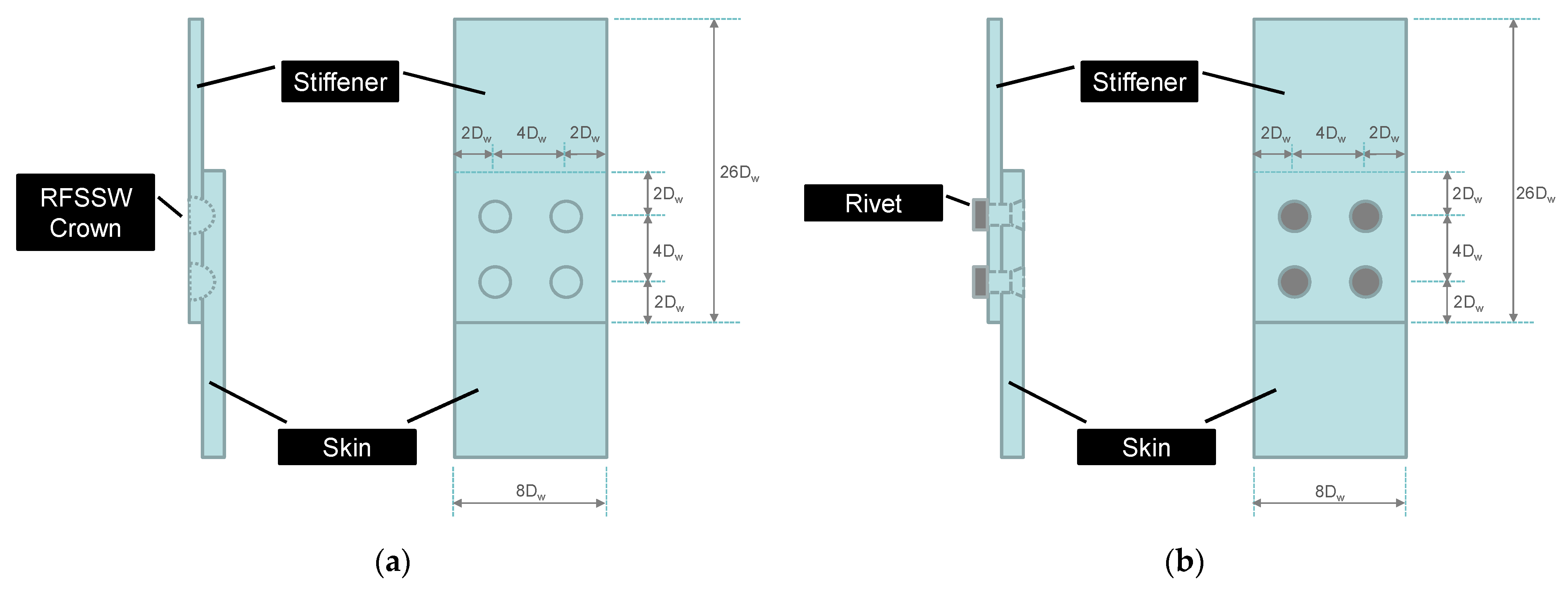
The NASM-1312-21 method covers the procedure and apparatus required for testing the shear joint fatigue of fasteners at room temperature [
24]. In this study, the fatigue load levels were 75%, 50%, and 25% of the ultimate shear load. Three RFSSW coupons and three rivet coupons were tested for each load level. The ratio between the minimum and maximum loads in each loading cycle was 0.1. The loading cycle frequency was 30 Hz. A specific guide fixture was used for keeping the coupon pieces straight during the fatigue test. The NASM 1312-21 coupon configurations for RFSSW and riveting are depicted in
Figure 6.
The mechanical test setups for NASM-1312-4, ISO-14272, and NASM-1312-21 are depicted in
Figure 7a,
Figure 7b, and
Figure 7c, respectively. These industrial test standards were used according to the Metallic Materials Properties Development and Standardization (MMPDS) Handbook [
20], which contains design information on the mechanical and physical properties of metallic materials and joints commonly used in aircraft and aerospace vehicle structures. The MMPDS Handbook has been reviewed and approved using a standardized process that involves certifying agencies, including major government organizations, material suppliers, and material users worldwide [
20].
3. Results
No specific standard is available for mechanically testing refill spot welds thus far. Therefore, to test refill spot welds, this study used conventional test standards that are typically used to test rivet joints. The presented study involved a comparison between the mechanical properties of refill spot welds and the mechanical properties of rivet joints. By considering this insight, the experiments used an RFSSW tool and a solid rivet of comparable sizes for producing refill spot weld coupons and rivet coupons in accordance with NASM-1312-4 [
22], ISO-14272 [
23], and NASM-1312-21 [
24].
Table 1 presents the coupon quantities.
There is a daunting challenge in drawing a viable comparison between RFSSW and riveting as they are two completely different joining methods in terms of their joint configurations, their joint compositions, and their joining processes. A refill spot weld is purely made from the base/parent metals without consuming any filler or foreign materials. In contrast, riveted joints consume solid rivets that are made of malleable, ductile metals for fastening. Riveting requires labor-intensive installation steps that require at least 8–10 s to be completed by a trained technician. In contrast, RFSSW takes about 2 s, from tool touch-down to tool removal, to be made by an RFSSW system. Refill spot welds exhibit a near-flush surface finish on the workpiece surfaces. In contrast, the solid rivets may exhibit a protruding rivet end that makes the surface uneven and aesthetically unpleasant. In addition, a refill spot weld does not have a head and a clenched end to mechanically grip the workpieces together like solid rivets do. So, the strength of a refill spot weld purely depends on the strengths of the weld zones thermomechanically created in the workpieces.
After producing refill spot weld coupons and rivet coupons, the coupons were mechanically tested in accordance with their associated test standards. The NASM 1312-4 static load lap shear test results are provided in
Figure 8a and
Figure 9. The ISO-14272 static load cross-tension test results are provided in
Figure 8b and
Figure 10. The NASM-1312-21 fatigue lap shear pull test results are presented in
Figure 11 and
Figure 12.
Overall, the RFSSW coupons demonstrated significantly higher ultimate lap shear strengths but slightly lower ultimate cross-tension strengths than those of the rivet coupons, as suggested by
Figure 8. As suggested earlier, a refill spot weld is made of the workpiece metals via thermomechanical processing, but a rivet joint is made by fastening a solid rivet. The workpieces used in this study are high-strength aerospace aluminum alloys that have much higher strengths than the solid rivet metal. Therefore, having a refill spot weld that has stronger lap shear strength than that of a comparable rivet joint is intuitive. However, a refill spot weld does not have a head and a clenched end to mechanically grip the workpieces together like solid rivets do, which perhaps explains why the ultimate tension loads of refill spot welds were slightly lower than the ultimate tension loads of rivet joints.
The fatigue test results in
Figure 11 and
Figure 12 indicate that both RFSSW coupons and rivet coupons demonstrated comparable performances during low-load-level fatigue lap shear tests. However, RFSSW coupons outperformed rivet coupons during high-load-level fatigue lap shear tests as the 75% and 50% load levels of the 4-refill-spot-weld coupons were higher than the ultimate loads of the 4-rivet-joint coupons. The 75%, 50%, and 25% load levels for RFSSW coupons were 20,952.9 N, 13,968.6 N, and 6984.3 N, respectively. The 75%, 50%, and 25% load levels for rivet coupons were 9770.9 N, 6514.0 N, and 3257.0 N, respectively. These load levels were based on the average ultimate shear load of 4-refill-spot-weld coupons and the average ultimate shear load of 4-rivet-joint coupons, which were 27,937.2 N and 13,027.9 N, respectively.
RFSSW coupons exclusively exhibited nugget pullout failures during static lap shear load tests and static cross-tension load tests, as shown in
Figure 9a and
Figure 10a. Riveted coupons exhibited rivet shear failures during static lap shear load tests, as shown
Figure 9b, and rivet pullout failures during static cross-tension load tests, as shown in
Figure 10b. All RFSSW coupons and rivet coupons demonstrated tensile failures in their stiffener pieces during the fatigue lap shear tests.
As a refill spot weld is an integral part of the workpieces, the refill spot weld strength purely depends on the strengths of the weld zones created by the welding process. Hovanski et al. [
25] studied the effects of the RFSSW process cycle time on the refill spot weld lap shear strength. The next section will discuss failure mechanisms demonstrated by refill spot welds.
4. Discussion
RFSSW produces different weld regions with different microstructures and mechanical properties. The heat-affected zone (HAZ) is a region that spans around the weld as its outermost shell in the heat-treatable base metal. It is affected by the process heat but not the mechanical stirring. Metal grain growth may occur in the HAZ of heat-treatable aluminum alloys due the process heat. The thermomechanically affected zone (TMAZ) is an interlayer shell between the HAZ and the weld nugget. It is affected by the process heat as well as the mechanical stirring of the welding process. The weld nugget is the core of the weld, where the tool forges and stirs the plasticized material together during the welding process. It experiences the greatest heat and plastic deformation followed by significant grain refinement and re-precipitation.
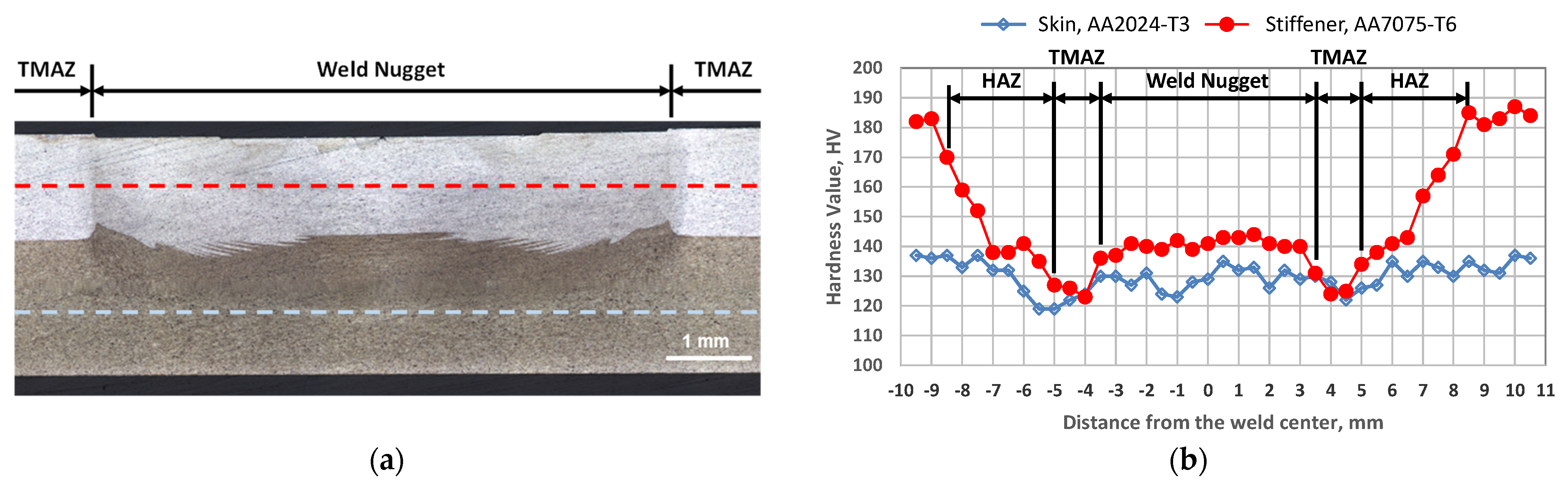
A refill spot weld cross-section image and its microhardness map are depicted in
Figure 13. The microhardness measurements in
Figure 13b are the Vickers hardness values sampled along the midplane lines of the stiffener sheet and the skin sheet of the weld cross-section specimen in
Figure 13a. Overall, the TMAZ and HAZ exhibit lower hardness values than the parent metal and the weld nugget, which perhaps means they have weaker mechanical strengths than the parent metal and the weld nugget. The effects of the TMAZ and HAZ on the mechanical properties of friction stir welds have been documented by many researchers [
16,
17,
18,
26].
The microstructure of RFSSW exhibits different grain sizes, precipitates, and substructures in different weld zones [
27]. A softened region consisted of the weld nugget and the TMAZ. The formation of the softened region can be attributed to coarsening and dissolution of the S-phase precipitates. With the increase in the RFSSW tool spindle speed, the hardness of the weld nugget decreases and the hardness profile of the weld changes from the W-shaped pattern to the U-shaped pattern along the mid-plane lines of the weld cross section [
27].
A refill spot weld usually starts to break in the weakest region of the weld under external loading.
Figure 9a and
Figure 10a show nugget pullout failures resulting from the static load tests. The rupture of the nugget pullouts exclusively occurred within the TMAZ or HAZ of the refill spot welds as the TMAZ and HAZ are considered the weakest regions of the coupon. During the fatigue tests, tensile failures were also initiated in the TMAZs of the 4-refill-spot-weld coupon and propagated into the parent metal, as shown in
Figure 12a.
In general, refill spot weld mechanical failures include nugget pullouts, interfacial failures, and parent metal tensile failures, as documented by Boldsaikhan et al. [
10].
A parent metal tensile failure is a transverse crack across the parent metal sheet, which is caused by the spot weld shear loading—in other words, the parent metal tensile loading. The crack usually originates in the TMAZ and/or HAZ of a refill spot weld and propagates into the parent metal.
A nugget pullout (NP) involves the weld nugget that is pulled out of the workpieces because of the rupture occurring in the TMAZ and/or HAZ around the outer edge of the spot weld.
An interfacial failure is a failure at the faying interface between the workpieces so that the interfacial bond fails to hold the workpieces together. It usually occurs within the bottom portion of the spot weld TMAZ if the weld nugget is defect free. An insufficient tool plunge depth or volumetric defect in the weld nugget may lead to an interfacial failure.
A refill spot weld may demonstrate one or a combination of these mechanical failures depending on external loading, parent metal properties, and weld properties. As discussed earlier, the RFSSW process produces different weld regions with different microstructures and mechanical properties. Assuming that the weld nugget is defect free, the TMAZ and HAZ in heat-treatable aluminum alloys are the weakest regions as they exhibit lower hardness values than the parent metal and the weld nugget. Therefore, a mechanical failure usually initiates in the TMAZ and/or HAZ and propagates into new evolving weakest regions of the workpieces under external loading.
The two-spot-weld coupons exclusively demonstrated nugget pullouts during the NASM-1213-4 static load test. The NASM-1312-4 test imposes shear loading on the spot joints. As the two-spot-weld coupon is unguided, it may deform during the shear loading, which, in turn, creates minor tension loading on the joints. Both shear and tension forces can contribute to the formation of nugget pullouts, as described in
Figure 14 for NASM-1312-4. The cross coupons also exclusively demonstrated nugget pullouts during the ISO-14272 static load test. During the ISO-14272 test, the spot weld experiences tension loading that caused the weld nugget to be pulled out of the parent metal, as depicted in
Figure 14 for ISO-14272. The four-spot-weld coupons exclusively demonstrated stiffener sheet tensile failures during the NASM-1312-21 fatigue test, as described in
Figure 14. The NASM-1312-21 fatigue test uses a guide fixture to make sure that pure shear loading is applied to the spot welds. No coupons demonstrated interfacial failures in this study.
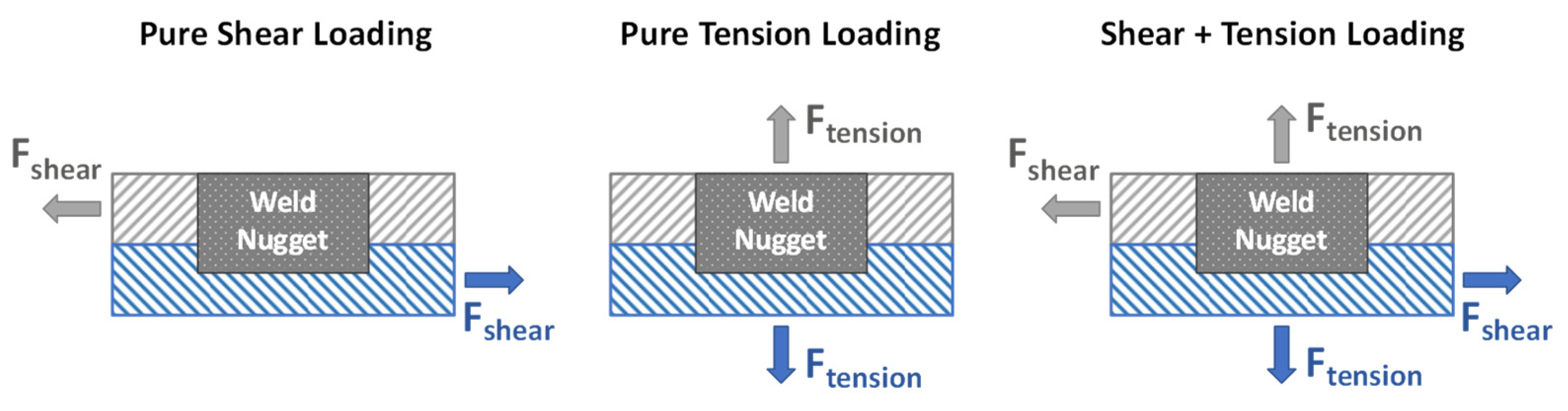
In this study, the mechanical tests examined the shear and tension strengths of refill spot welds through applying shear loading and/or tension loading, as explained earlier. Generally, external loading may impose pure shear loading, pure tension loading, or coupled shear-and-tension loading on a refill spot weld, as illustrated in
Figure 15. When external loading exceeds a tipping point, a refill spot weld exhibits mechanical failures in its weakest region, as illustrated in
Figure 16 and
Figure 17.
Under pure shear loading, a refill spot weld may demonstrate a stiffener sheet tensile failure, a skin sheet tensile failure, or an interfacial shear failure, as illustrated in
Figure 16a. The failure mechanism chooses the weakest region to fail first. A refill spot weld demonstrates a stiffener or skin sheet tensile failure if the stiffener or skin sheet is the weakest region. Pure shear loading on the refill spot weld imposes pure tension loading on the parent sheet metals. Therefore, the parent metals may exhibit tensile failures under pure shear loading. In addition, a refill spot weld demonstrates an interfacial shear failure, as illustrated in
Figure 16a, if the interfacial bond is the weakest region. Factors that make a particular region the weakest region include any possible defects, the properties of the parent metals, and the properties of the weld regions. The properties can be geometric, metallurgical, and/or mechanical.
Under pure tension loading, a refill spot weld may exhibit a stiffener sheet nugget pullout, a skin sheet nugget pullout, or an interfacial tension failure, as illustrated in
Figure 16b. The failure mechanism chooses the weakest region to fail first. A refill spot weld demonstrates a nugget pullout if the TMAZ or HAZ in the stiffener or skin sheet is the weakest region. A nugget pullout is a shear failure within the TMAZ or HAZ. Pure tension loading on the refill spot weld imposes pure shear loading on the parent sheet metals. In addition, a refill spot weld demonstrates an interfacial tension failure, as illustrated in
Figure 16b, if the interfacial bond is the weakest region.
Under coupled shear-and-tension loading, a refill spot weld may demonstrate a combination of failures associated with the pure shear loading and the pure tension loading, as illustrated in
Figure 17. Again, the failure mechanism chooses the weakest region to fail first. Factors that make a particular region the weakest region include any possible defects, the properties of the parent metals, and the properties of the weld regions. The properties can be geometric, metallurgical, and/or mechanical.
Figure 15,
Figure 16 and
Figure 17 illustrate external loading conditions of a refill spot weld and its failure mechanisms. A refill spot weld may demonstrate one or a combination of mechanical failures, depending on external loading, parent metal properties, and weld properties. As the TMAZ and HAZ exhibit weaker strengths than the parent metal and the weld nugget, a mechanical failure of a refill spot weld usually initiates in the TMAZ and/or HAZ and propagates into new, evolving weakest regions of the workpieces. Understanding these phenomena is necessary to design damage-tolerant refill-spot-welded structures.
5. Conclusions
Industrial standards that are typically used for testing rivet joints were implemented in this study to evaluate the mechanical properties of refill spot welds. Therefore, the presented study involved a comparison between the mechanical properties of refill spot welds and the mechanical properties of rivet joints. With that being said, the presented study used an RFSSW tool and a solid rivet of comparable sizes for producing refill spot weld coupons and rivet coupons. The RFSSW coupons demonstrated significantly higher ultimate lap shear strengths but slightly lower ultimate cross-tension strengths than those of the rivet coupons. As suggested earlier, a refill spot weld is made of the workpiece metals via thermomechanical processing, but a rivet joint is made by fastening a solid rivet. The workpieces used in this study are high-strength aerospace aluminum alloys that have much higher strengths than the solid rivet metal. Therefore, having a refill spot weld that has stronger lap shear strength than that of a comparable rivet joint is intuitive. However, a refill spot weld does not have a head and a clenched end to mechanically grip the workpieces together like solid rivets do, which perhaps explains why the ultimate tension loads of refill spot welds were slightly lower than the ultimate tension loads of rivet joints. The fatigue test results indicate that both RFSSW coupons and rivet coupons demonstrate comparable performances during low-load-level fatigue lap shear tests. However, RFSSW coupons outperformed rivet coupons during high-load-level fatigue lap shear tests as the 75% and 50% load levels of the four-refill-spot-weld coupons were higher than the ultimate loads of the four-rivet-joint coupons.
Refill spot weld mechanical failures include parent metal tensile failures, nugget pullouts, and interfacial failures. A refill spot weld may demonstrate one or a combination of these mechanical failures, depending on external loading, parent metal properties, and weld properties. The RFSSW process produces different weld regions with different microstructures and mechanical properties. Assuming that the weld nugget is defect free, the TMAZ and HAZ of heat-treatable aluminum alloys are the weakest regions as they exhibit lower hardness values than the parent metal and the weld nugget. Therefore, a mechanical failure usually initiates in the TMAZ and/or HAZ and propagates into new, evolving weakest regions of the workpieces under external loading. In general, the failure mechanism chooses the weakest region to fail first. Factors that make a particular region the weakest region include any possible defects, the properties of the parent metals, and the properties of the weld regions. The properties can be geometric, metallurgical, and/or mechanical.
Although the mechanical tests of refill spot welds demonstrated promising results with predictable failure mechanisms, the metallurgical evolution involved in RFSSW remains a subject to study. In addition, RFSSW will need thorough standards and specifications to implement it in aerospace applications.


 ,
, 


