1. Introduction
Drones have become an indispensable component of modern equipment systems, and as the number of components in these systems continues to increase, so does their complexity. Consequently, the requirements for system quality—particularly reliability, maintainability, and functionality—are also becoming increasingly stringent [
1]. In recent years, there have been numerous instances of serious consequences and economic losses caused by quality problems in aerospace and other fields. As a result, safety and reliability have become key areas of focus when it comes to drones [
2]. Sensor data fusion [
3], fault detection [
4], fault-tolerant estimation [
5], and fault-tolerant control [
6] are all important means of ensuring UAV safety. Among these methods, researchers tend to place particular emphasis on fault detection, which can be broadly divided into two categories: model-based approaches and data-driven approaches [
7].
The traditional way to detect drone failures is through model-based approaches that use mathematical models to analyze UAV safety. These models can be further subdivided into qualitative or quantitative methods (
Table 1). However, because model-based approaches often focus only on specific components, they may not always detect failures in other parts of the system. This means that, if an unmanned aerial system suddenly fails due to its complexity, resulting in higher costs, multiple model pairs may need to be deployed. Therefore, in this study, we mainly study faults at the system level. Building a fault mode database using a large amount of fault data can facilitate the analysis of fault modes and fault propagation processes at the system level. The analysis process can help fault diagnosis personnel quickly locate the problem and save diagnostic time. At present, the research on failure mode databases lacks depth. Drone systems are complex systems with multiple tasks and configurable elements. There are both common and unique failure modes among different systems. The evaluation center where the authors of the current study work has a large body of failure data. However, due to the lack of organization and induction of these data, there has been no in-depth analysis of the mechanisms of common faults. How to use historical fault data to generate fault mode databases and utilize these databases to better achieve fault detection is a problem worth studying.
Another typical method used for drone fault detection is the data-based method. In recent years, the reduction in the difficulty of data collection and analysis has driven the development of the field of data analysis. With the support of various high-speed processors, the means of mining required information from data have become increasingly powerful. Similarly, data-based methods can be divided into two categories: quantitative and qualitative. Quantitative methods include those based on statistical theory and neural networks. Qualitative methods typically include expert systems, fuzzy logic, pattern recognition, and qualitative trend analysis.
Table 2 lists some typical studies, including the location of fault detection and the methods used.
Working out how to optimize the original data or improve the relevant algorithms has also become a major research trend in recent years. Zhang et al. [
22] proposed a robust deformed denoising CNN (RDDCNN) to solve the offset pixels of feature maps from noisy images. This approach can effectively improve data quality and support data-based UAV fault diagnosis. Tian et al. [
23] proposed a multi-stage image denoising CNN with a wavelet transform (MWDCNN) via three stages. A dynamic convolution is used in a CNN to address the limitations in depth and width of lightweight CNNs to achieve good denoising performance.
The performance of data-based methods mainly depends on the quality of the original data. The fault data of drones is often multi-level linkage and cross-influence data, which is not conducive to analyzing complex types of faults. In addition, data-based methods are often offline and difficult to analyze in real time. This method cannot support the real-time safety monitoring of drones. It is more of a means of analysis after accidents, and cannot detect and handle abnormal situations during the operation of drones. Therefore, this method cannot guarantee the safety of drones during operation.
The above two methods mainly focus on component-level fault detection, rather than system-level fault analysis and localization. In this study, our goal is to fully explore and utilize drone fault data accumulated over the past year to gain a deeper understanding of drone system-level fault mechanisms. The aims of this study are: (1) To fully utilize a large amount of drone fault data, establish a fault mode database, and identify the occurrence and propagation modes of drone faults. To further extract fault features and attributes from fault modes and condense them into safety attributes during drone operation for subsequent runtime verification processes. (2) To design and implement a monitoring generation algorithm and code detection framework for real-time monitoring of whether drones violate a certain safety attribute during operation. By using the runtime monitoring method, the operation process of unmanned aerial vehicles can be monitored in real time and faults can be quickly detected.
The rest of the paper is organized as follows:
Section 2 presents the related works about failure mode databases and runtime verification. Research on security detection based on failure mode databases is included in
Section 3.
Section 4 describes the implementation of a monitor generation framework and linear timing logic extension. The Clang-based code instrumentation framework is explained in
Section 5. Experimental design and methodological evaluation are described in
Section 6. Finally,
Section 7 concludes the paper.
2. Related Works
2.1. Failure Mode Databases
In recent years, failure mode databases have become a research hot spot in database system engineering, knowledge engineering, and other fields, and this approach has been applied in many fields. Failure mode databases are structured, easy-to-use, comprehensive, and organized failure clusters—a collection of interrelated patterns stored, organized, managed, and used in computer memory in a certain way in order to solve the needs of problems in some fields. These failure modes include theoretical knowledge related to the domain, factual data, and heuristic knowledge derived from expert experience. UAV failure mode databases are of great significance to the study of reliability trends. How to form a real scientific failure mode database is one of the key contents of the research.
A common solution to this problem is to extract UAV failure patterns from the records contained in a UAV accident database by cleaning, parsing, and normalizing the fault data. For example, by obtaining accident records from different countries and analyzing the causes of accidents. Suitable data sources include:
NASA and the FAA Aviation Safety Reporting System (ASRS) [
24];
U.S. Aviation Safety Communique (SAFECOM) data [
25];
Australian Transport Safety Bureau (ATSB) aviation safety investigations and reports [
26];
UK Air Accident Investigation Branch (AAIB) data [
27].
The attribute fields in the database should include the data source, accident year, month, location, flight phase, aircraft model, flight hour history, flight time of the mission prior to the accident, altitude, weather, mission being performed, root cause, and accident outcome. At present, the research on UAV accident databases mainly focuses on the collection and analysis of accident data. Wild et al. [
28] collected and analyzed 152 incident and accident records, but only 40 records deal with UAV accidents, and the data date back to 2006–2015. More recently, a total of 160 accident reports from 2015 to 2020 were collected and documented in an integrated database [
29].
At present, the study of failure mode databases lacks depth. UAV systems are complex systems with multiple tasks and configurable elements. There are both common and unique failure modes among different systems. In addition, the reliability level of UAVs in different regions varies greatly due to manufacturing differences. The evaluation center where the authors of this current study work has a large amount of fault data of various types of UAVs in China, but these data have not been sorted and summarized and the mechanisms of common faults have not been thoroughly analyzed. How to make use of historical fault data to generate a fault mode database and realize fault detection better is a problem worth studying. UAVs face the following major problems:
- (1)
There has been a lack of unified analysis and summarizing of accumulated equipment failure data and underutilization of the advantages of historical data.
- (2)
Lack of effective fault identification, characterization, and matching methods to provide guidance for the whole life cycle activities of UAVs. Implementing such methods could effectively avoid the introduction of software defects and avoid the occurrence of failures, thus improving the reliability of unmanned aerial systems.
In this paper, the construction of a fault module database provides a set of solutions from cause analysis to normalized fault representation. Based on this database, we can have a deeper understanding of the development trends and failure modes of UAVs and improve the reliability and safety of UAVs.
2.2. Runtime Verification
Runtime verification techniques are formal verification techniques, which use logical formulas to describe properties and transform them into formal structures. Runtime verification tends to check that there is a poor path, that is, up to the current time, whether the system’s running path is within safety parameters. After being proposed, this method has received continuous attention from academia and industry. One of its characteristics is that it plays a role in the system software—it is in the real run environment used to monitor the system—so it can find potential defects that the traditional software testing method misses. It complements classical verification techniques (for example, theorem proving and model checking) and provides a more practical method for the verification of system running trajectories. At the cost of limited execution coverage, runtime validation provides accurate information about the runtime behavior of the monitored system for subsequent analysis. The object of action can be a software system, a hardware or information physical system, a sensor network, or any system where dynamic behavior can be observed. The following is a brief overview of some recent research on runtime validation.
Abbas et al. [
30] introduced private runtime verification. Liu et al. [
31] introduced the idea of incremental verification and proposed an incremental probabilistic model-checking method based on heuristics. Y-Rozier et al. [
32] explore the connection and difference between simulation and runtime verification. Stockmann et al. [
33] proposed architecture runtime verification. Teixeira et al. [
34] studied the properties of a runtime verification-specified API and wrote a minimalist specification language. Bicevskis et al. [
35] discuss data quality checking during the execution of a business process by using runtime verification. Lee et al. [
36] developed an effective model-checking method for IoT system operation verification. Legunsen et al. [
37] proposed an aware runtime verification technique. Geng et al. [
38] introduced a new smart tagging method to verify the completion of tasks involving one-to-many and many-to-one dependencies. Ring et al. [
39] significantly reduced the size of the state space of the verification process and reduced the complexity of the detection process. Ye et al. [
40] proposed an adaptive runtime verification method based on multi-agent systems. Tsigkanos et al. [
41] proposed a service-oriented software architecture and technical framework to support the runtime verification of decentralized edge-dense systems. Hu et al. [
42] proposed a runtime verification method based on the Robotic Operating System (ROS). Tracy et al. [
43] introduced an open-source framework to achieve efficient and high-performance runtime monitoring. Ye et al. [
44] developed a new approach based on approximate computation to achieve sufficiently fast and accurate repeated execution of security verification. Kong et al. [
45] proposed a method aimed at monitoring traces that reveal the runtime state of the software. Jung et al. [
46] proposed an automatic runtime prioritization method based on a classification tree. Miranda et al. [
47] proposed a method to automatically detect whether the errors reported by the monitor are real errors. The authors of [
48] proposed the concept of UAV safe operation monitoring and the operational limits to be monitored. A prominent example of such operational limitations is geofencing. Geofencing uses virtual fencing to prevent drones from entering restricted airspace. Felipe et al. [
49] proposed a solution based on stream runtime verification, which offers a high-level declarative language to describe sophisticated monitors together with guarantees on execution time and memory usage. They showed how monitors can be combined with temporal planning not only to monitor assumptions but also to support mitigation and remediation in UAV missions. Bonnah et al. [
50] presented a rewriting-based algorithm for runtime monitoring of safety requirements expressed in TWTL for specifying time-bounded serial tasks.
Runtime verification is widely used in academia and industry to ensure the reliability and security of the system, whether it is before deployment, testing, verifying, debugging, or after deployment. However, the setting of monitoring conditions still lacks a solid basis. Therefore, this paper intends to analyze the failure mechanism of UAVs through the UAV failure mode database to extract the monitoring conditions. According to the above monitoring conditions, the UAV is monitored in real time to improve its reliability.
3. Research on Safety Detection Based on Failure Mode Databases
Drones play a vital role in modern equipment, showing the characteristics of increasing scale and complexity. In the face of more serious quality and reliability problems, the guarantee of equipment software presents new challenges. Therefore, in order to give full play to the value of existing fault data, this paper collects and analyzes UAV faults based on the collected fault data, generates a fault mode database, and identifies and locates the faults during the operation of the UAV by combining this database with runtime verification technology.
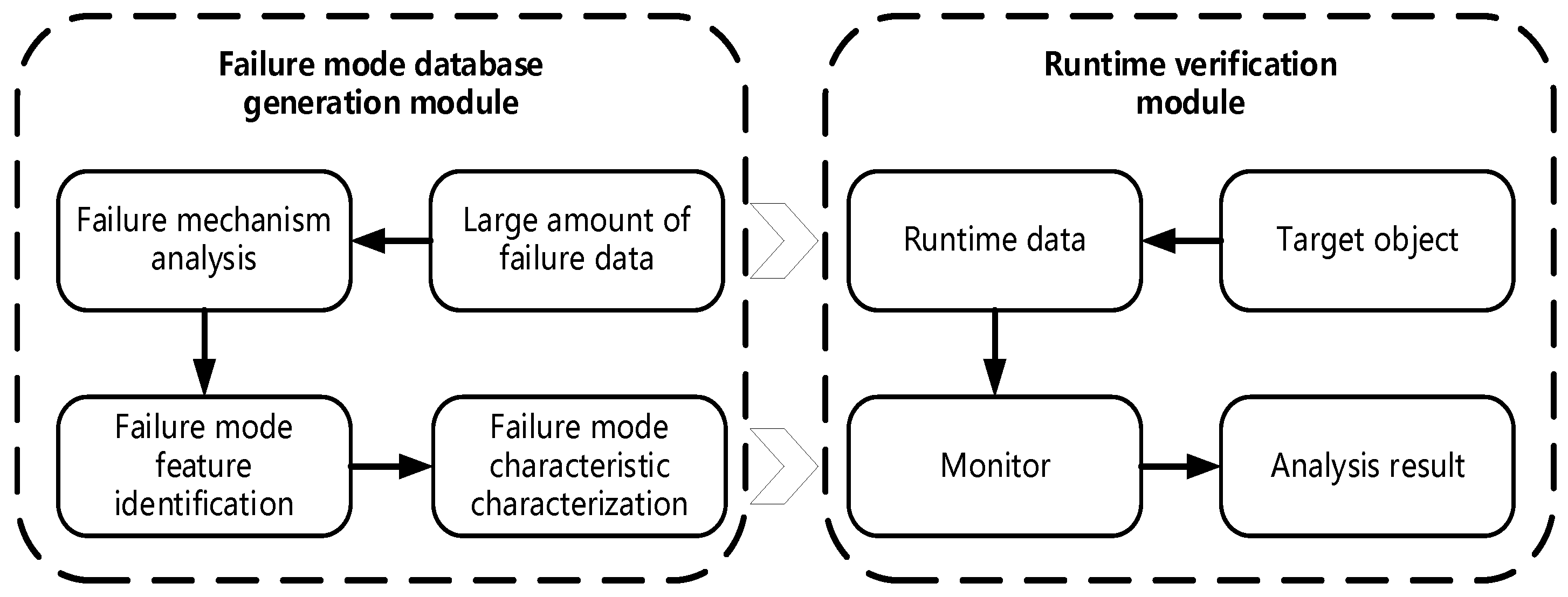
The overall research framework of this paper is shown in
Figure 1.
- (1)
First, a software-based failure mode database is constructed. The evaluation center at which the authors of the current study work has a large body of fault data; in order to better realize its value, it is necessary to summarize it into a fault mode database. In this paper, fault mechanism analysis is carried out to summarize the failure causes and fault propagation modes of unmanned aerial vehicle systems. Then, the failure mode feature identification method is used to extract the failure characteristics. Finally, the method of characterizing the failure mode characteristics is studied. After extracting the attributes of each characteristic, the features of each attribute of the fault data are described. According to the results of the above process, the safety attributes that must be observed during the operation of the UAV are derived and the detection content is provided for use by the verification process during the subsequent operation.
- (2)
Second, runtime verification is implemented. To achieve this, linear time logic is used to describe safety attributes. Spot is used to complete the conversion process from LTL to the monitor, with some modifications being made to Spot according to actual needs. When combined with the safety attribute description derived in the failure mode database building step, this process allows the running state of the UAV to be monitored in real time.
3.1. Failure Mechanism Analysis
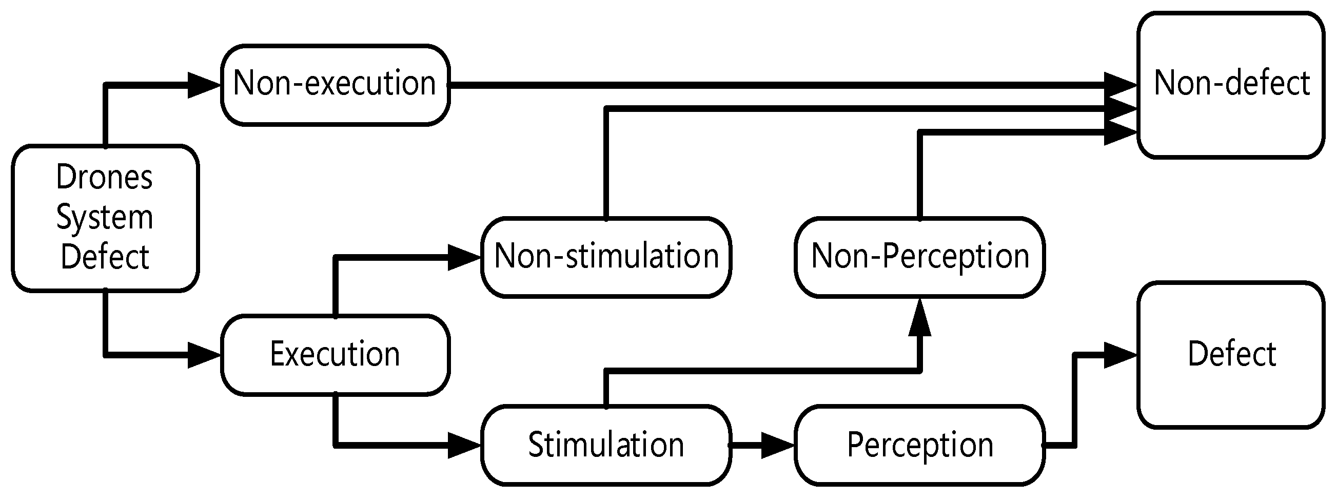
A system defect is a condition in which the system does not conform to specified requirements and behaves in ways inconsistent with the desired way of use. System defects, which are introduced by human errors, are static inherent properties of the system and are present across the whole system life cycle. During system execution, defects are activated under certain conditions. A system fault is an abnormal condition in a component, device, or subsystem. System failure occurs when a system fault cannot be handled by fault-tolerant technology, resulting in the loss of all or part of the functions of the system during operation and deviation from the expected normal state.
According to the process of occurrence, three necessary and sufficient conditions for system failure caused by system defects can be described:
The actual input the system receives causes the system defect to be executed;
An executed defect causes a change in the state of the data after the location of the system defect (failure is triggered);
Faulty system data is passed as a result (the user perceives a fault).
These three necessary and sufficient conditions also reflect the whole process of the fault produced by the defect. This process is sequential, after the system executes a defect, the defect causes the data state after the defect to be infected, and finally, after several iterations, the wrong data is output by the system.
Figure 2 describes the mechanism of system failure and reflects the conditions of fault identification and discovery. These three conditions correspond to the probability that the input leads to the execution of the position (execution probability), the probability that the position mutation leads to the change of the data state, (contagion probability), and the probability that the changed data state leads to a change in the program output (propagation probability). Only when these three conditions are met can the defect produce a fault and be identified.
3.2. Failure Mode Feature Identification
The system fault pattern feature identification process needs requires a features analysis of function, execution, interface, and related constraints. Through functional analysis, execution analysis, and interface analysis, the understanding of the identified features is strengthened, which lays a foundation for improving the accuracy of system fault pattern matching. Failure data description begins with original attribute extraction.
The complete system properties are extracted using the method given in the IEEE 1044–2009 standard. At the same time, the ideas of the GJB 437-88, GJB/Z 1391-2006, and GJB 841-90 standards are referenced. The attributes are modified from the perspective of fault control and management. The extracted attributes are normalized so that modifying one attribute does not affect other attributes. Finally, attribute fields that consider efficiency and quality that are accurate and easy to reuse later are extracted.
First, the fault ID and fault description attributes in IEEE 1044–2009 are used and the system (subsystem and subsystem), product model, product batch, and collection date are added as the basic information of fault data. Second, the fault state attribute is used to give the overall expression of the fault. The severity and impact attributes are used and then changed to fault-level and potential-impact attributes. If the type attribute is used, it is changed to a fault-type attribute. Third, the injection activity and discovery activity attributes are used. From the perspective of fault discovery and introduction, it is modified into the attributes of the fault discovery and introduction stages. Next, the fault or failure performance, modification content, and modification measure attribute are given. Finally, the root cause of a fault is considered and the attribute of the cause of the fault is added. A list of the attributes generated from fault data is given in
Table 3.
3.3. System Failure Mode Characteristic Characterization Method
According to the characteristics of different system fault patterns, measurement parameters, data acquisition methods, and deviation thresholds are designed. These provide the basis for accurate system fault pattern matching.
After extracting the characteristic attributes, the features of each attribute of the fault data must be described. The attributes are the same from data entry to data entry, but the characteristics of each attribute are different. Below, we describe the model and standardized description of system fault data.
For specific fault attributes, the attribute’s characteristics must be described and the attribute’s value range must be specified. The characteristics determined in this process should be consistent with the run characteristics of the system and can reflect the characteristics of system faults. How to improve reusability and meet the use needs of various developers should also be considered.
The existing feature description method of system fault data is mainly natural language, but this approach is prone to subjectivity. Due to differences in how individuals think, fault descriptions have a high degree of individuation and poor portability. In this paper, formalized and normalized expressions are developed to describe the characteristics of attributes. The different ways of describing attribute characteristics are given in
Table 4.
Attribute description is the key to fault description. Through the feature description method, the ambiguity caused by the use of over-subjective natural language is solved, which is conducive to the quantitative analysis of data and improvement of the value of fault data utilization. The main contribution of fault data attribute feature definition to fault data description is the provision of fault type features based on input class, output class, processing logic class, and working state class. These four classes are also the core and main features of any fault description, which is conducive to improving the efficiency of collecting and managing subsequent fault data. Finally, after fault data attribute extraction and provision of the feature description method, the system fault data description method is provided. The system fault pattern library is sorted according to the fault description method and subsequent management becomes rule-based.
Table 5 provides the failure modes related to drone functions. Due to space constraints, only some of the failure modules are listed here as an illustration.
4. Monitor Generation Framework Based on Linear Temporal Logic
In this study, we take unmanned aerial vehicle systems as the research object, focusing on safety monitoring technology based on runtime verification, with a focus on solving the problem of how to generate the required monitors and how to connect them with source code. This section focuses on the former, which is how to generate monitors and achieve target monitoring operations.
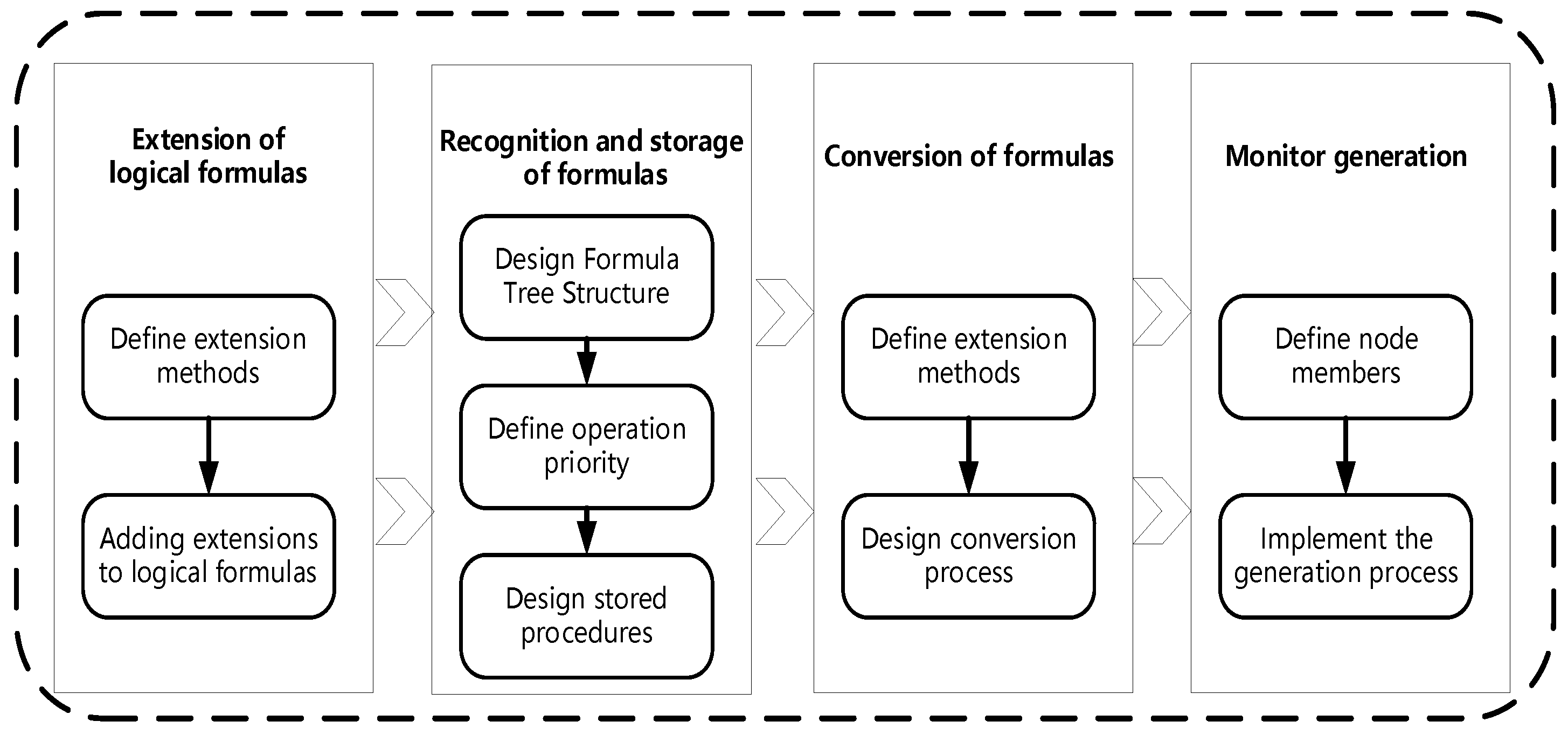
Figure 3 shows the overall flowchart of the framework.
The entire framework can be divided into four parts. First, based on the different test objects and requirements documents, the properties that the tested system should meet during runtime are organized and described in natural language. In order for computers to handle these safety requirements, they need to be transformed into formal descriptions. In this study, we chose to use linear temporal logic to describe safety attributes, and we extended LTL to enhance its expressive ability, achieving the effect of using more concise forms to describe richer meanings and enhancing the accuracy of property descriptions. Second, in this study, we define a formula tree structure and corresponding conversion algorithms, which will be used by computers to store formulas after reading them. Once again, the conversion rules for extended LTL formulas were defined and the extended formulas were simplified according to this rule to obtain the transformed LTL formula tree. Next, the conversion algorithm is used to convert the logical formula into the corresponding security requirement monitor. The monitor will receive data from the tested object for analysis and perform state migration based on the analysis results. If the data meet the safety requirements, the monitor can execute the task smoothly. If the data violate the safety requirements, the monitor will discover this issue and issue a warning. The purpose of a warning is to draw the attention of the operator, who can promptly view system information, handle problems, and reduce the probability of accidents.
The following sections will introduce the approach in detail:
Section 4.1 describes the extension of the meaning of linear temporal logic,
Section 4.2 describes the formula recognition and storage process,
Section 4.3 describes the formula conversion process, and
Section 4.4 describes the monitor generation process.
4.1. Extension of Linear Temporal Logic
There are four commonly used logical connectives in linear temporal logic, namely, G, F, U, and X. G is a unary operator, indicating that the formula must be constant; F is a unary operator, indicating that the formula will be established in the future; X is a unary operator, indicating that the next cycle formula needs to be established; and U is a binary operator, which means that the formula on the left should always be true until the formula on the right is true. In order to enhance the expressive power of LTL, in this study, we extend LTL to express richer meanings with more refined formulas and increase the flexibility and accuracy of the formulas. In this study, we add a time point or interval after the temporal operators G, F, U, and X. The meaning of [i] is that the operator should hold in the i-th cycle, while [i: j] means that the operator should hold at the beginning of a cycle and continue for j cycles. For ease of understanding, the following specific examples are given:
- (1)
After expansion, the expression ability of the formula has been improved and more concise formulas can be used to express richer meanings; the flexibility has also been improved.
- (1)
Assuming a represents an event, then a must hold true in all states, which is somewhat like an intersection. Only when a holds true in all states can it be considered true and as long as a does not hold true in one state, it does not hold true. Operators have their usage scenarios, but they may not be as flexible. If you want a to hold true in the next three states, it doesn’t matter if the other states hold true, as the G operator cannot.
- (2)
However, after adding a time interval, G[1:3]a can be used to indicate that a holds in the next three states. If traditional LTL is used, this must be represented with Xa&XXa&XXXa. If there are more than three states, the length difference of the formula will be even greater.
- (2)
After expansion, the expression accuracy of the formula has also been improved.
- (1)
Fa indicates that a will always hold in the future, which is somewhat like a union. As long as a holds in one state, then Fa holds. The problem with the F operator is that it has a high degree of uncertainty. We request that a be true in the future, but we don’t know when it will be true—it may be the 100th or 1000th state, etc.
- (2)
However, after adding a time interval, it is possible to define a time range and require that the F formula be valid within that time range. F[1:4]a means that a should hold at least once in the following four states for the F formula to hold. With time constraints, the meaning of the formula becomes clearer and effectively improves the uncertainty of the F operator.
It can be seen that the extended LTL formula can express richer meanings with shorter formulas, increase the accuracy of the formula, and be more intuitive to use. Because the writing of logical formulas requires manual completion, this extension can reduce the burden on operators, reduce the difficulty of formula writing, and make the process of formula writing easier to complete.
4.2. Recognition and Storage of Formulas
The property specification in this study is represented by LTL, which has been extended in the previous section to simplify the writing difficulty of LTL formulas. How the LTL formula is processed is described below. To accomplish this, in this study, we define an LTL formula tree and corresponding conversion algorithm.
When obtaining an LTL formula, it is necessary to first store it for subsequent operations. Choosing a suitable data structure to store the formula can make subsequent processing more convenient. The operators in the LTL formula include logical operators and temporal operators and there is an order of priority to their execution. In addition, parentheses can also be used in the LTL formula to express high priority. The operation results of high-priority subformulas may serve as input variables for other subformulas. Based on the above points, this paper selects a tree structure to store formulas and defines a formula tree structure. All leaf nodes of the tree are propositional variables and all non-leaf nodes are operators. Because trees naturally have classification properties, they are suitable for splitting formulas, and the root node of one subtree is the leaf node of another subtree, which is similar to the “operation results of high-priority subformulas will serve as input variables for other subformulas” mentioned earlier.
Before executing the storage algorithm, you need to define the priority of the logical connective and temporal operator in the LTL formula to avoid priority conflicts during algorithm execution. Operator priority follows the following three rules:
- (1)
The priority of a unary operator is higher than that of a binary operator.
- (2)
The unary logical connective has the same priority as the unary temporal operator and the binary logical connective has the same priority as the binary temporal operator.
- (3)
Operators within parentheses have higher priority than those outside parentheses. The more layers of parentheses, the higher the priority.
Based on the above rules, in this study, we provide a ranking of priorities, as shown in
Table 6. The priority of the three tables decreases from top to bottom, with operators in the same table having the same priority. Whatever operator has the highest relative position, has the highest priority.
- (1)
If the currently read object is a propositional variable, add it to the propositional variable stack.
- (2)
If the currently read object is an operator, compare the symbol priority of that operator with the top of the operator stack.
- (1)
If the top of the stack is empty, the current operator is directly pushed onto the stack.
- (2)
If the priority of the operator is higher than or equal to the top of the stack operator, then the operator is added to the operator stack.
- (3)
If the priority of the operator is lower than the top of the stack operator, the top of the stack operator will exit the stack.
- (1)
If the outbound operator is a unary operator, take an object from the propositional variable stack and construct a subtree. Using a unary operator as the parent node and an object as the right child node. Add the subtree to the propositional variable stack and repeat step (2) until the operator is added to the stack.
- (2)
If the outbound operator is a binary operator, take two objects from the propositional variable stack and construct a subtree. The binary operator is used as the parent node, the object that first exits the stack is used as the right child node and the object that exits the stack later is used as the left child node. Add the subtree to the propositional variable stack and repeat step (2) until the operator is added to the stack.
- (3)
If the current operator is a left parenthesis, it is directly pushed onto the stack.
- (4)
If the current operator is a right parenthesis, the top of the stack operator will exit the stack.
- (1)
If the stack operator is a left parenthesis, the current round of processing ends and the next object is read in
- (2)
If the stack out operator is a unary operator, take an object from the propositional variable stack and construct a subtree. Using a unary operator as the parent node and an object as the right child node. Add the subtree to the propositional variable stack and repeat step (4) until (4.1) is established.
- (3)
If the outbound operator is a binary operator, take an object from the propositional variable stack and construct a subtree. The binary operator is used as the parent node, the object that first exits the stack is used as the right child node and the object that exits the stack later is used as the left child node. Add the subtree to the propositional variable stack and repeat step (4) until (4.1) is established.
After the above process, the tree representation structure corresponding to the LTL formula can be generated.
4.3. Conversion of Formulas
In the previous section, an LTL formula tree was used to store extended LTL formulas. The description of how the formula is transformed to reduce the complexity of the temporal operators is given below.
Table 7 gives the conversion rules applied in this study. In the table, f
1 is the category of formulas to be converted and f
2 is the specific conversion operation. The conversion process is to operate on the LTL formula tree generated in the previous section. The rules in this study are defined recursively and the tree structure naturally has recursive properties, so the two are easy to combine.
To explain the conversion process, the following example is provided:
For formula , when i is greater than 0, the formula needs to wait for i cycles to be established. In this study, we deal with i through recursion, adding an x operator before the formula to be processed each time and then recursing through the i − 1 layer until the recursion is completed when i = 0. The corresponding operation in the tree is to generate a node representing the X operator to replace with as its right child node and then recursively process the right child node.
4.4. Monitor Generation
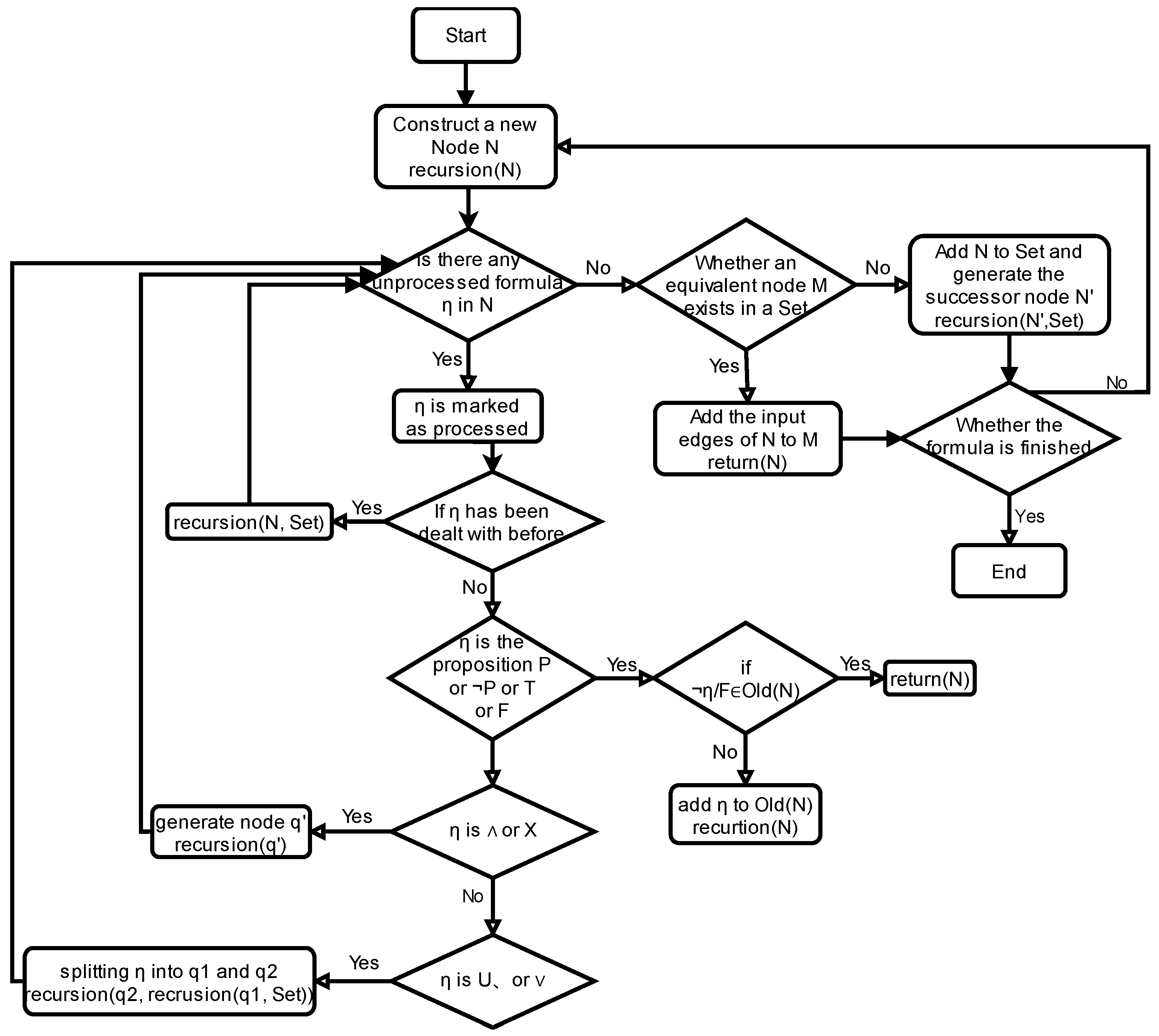
In the previous process, the conversion of the formula was completed. Next, it is necessary to convert the LTL formula into a monitor. In this study, formulas are processed from the outside to the inside, where ‘inside’ and ‘outside’ refers to priority, with external operators having lower priority and internal operators having higher priority. Correspondingly, in the formula tree, the lower the level of an operator node, the closer it is to the outside, while the higher the level, the closer it is to the inside. For a subformula, the outermost operator is the root node of the corresponding subtree, and accessing the root node is simpler than accessing the left and right subtrees, indicating that the LTL formula tree plays a positive role.
In this study, we use
to assign values to each member of a node. For example,
means adding formula
to the
list of the current node. The program processes the
list structure accordingly, where the nodes in
and a special node
together form all the states of the monitor. Here,
is the initial state of the monitor, and
is initialized as empty. In the following algorithm, function
creates a unique node
value every time it is called. Function
is taken as the Inverse function,
, where A is a proposition.
Figure 4 shows the process of generating a monitor.
5. Clang-Based Code Instrumentation Framework
This section introduces the relevant content of the code instrumentation framework, and the overall process is shown in
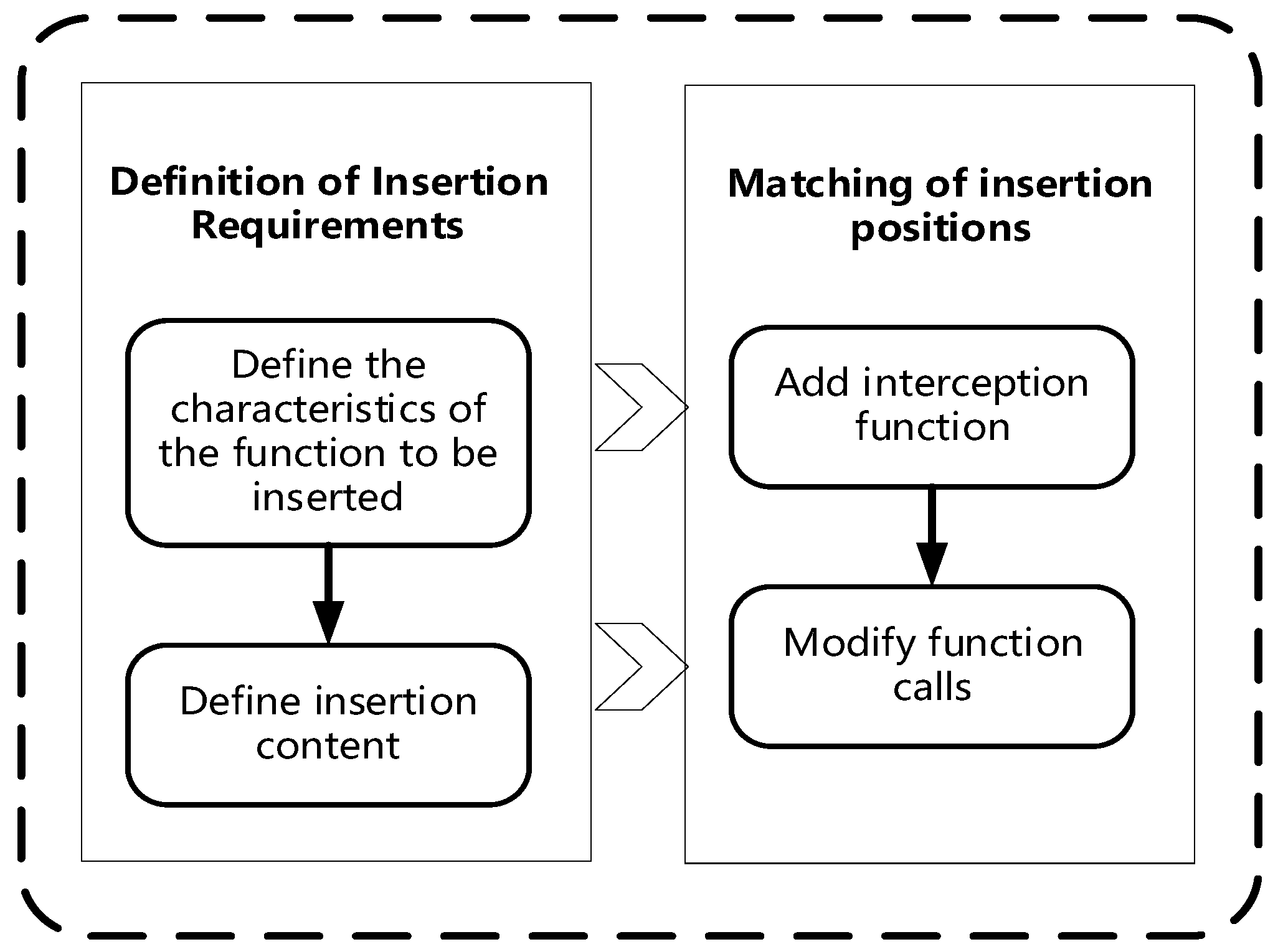
Figure 5. First, a definition of instrumentation requirements is required. This process involves writing instrumentation requirements files that describe the characteristics of the functions to be instrumented and the content to be instrumented. The second step is to match the insertion position, which requires writing a suitable matcher based on the insertion requirements. The matcher’s function is to find the insertion point that meets the requirements given in the target program. Finally, the execution of the instrumentation action will add interception functions at the matched instrumentation points and modify function calls in the target program. The process is detailed below.
Section 5.1 introduces the definition of pile insertion requirements and
Section 5.2 introduces the matching of pile insertion positions.
5.1. Definition of Stake Insertion Requirements
The instrumentation requirement file needs to include several elements. First, the characteristic of the function to be instrumented (return value type, name, parameter) needs to be included. This is used to locate the relevant position in the source code. The more detail included about the feature, the more accurate the matching position will be. Second, the content and the corresponding location of the pile to be inserted need to be included. The content refers to the specific code to be inserted and the pile location refers to the code that can be inserted before and after the pile insertion point.
In this study, we investigated two methods of stake insertion: (1) to directly stake the definition of the objective function, and (2) to plug in a brand new function, which will call the target function and modify the call statement of the target function to the call statement of the new function to achieve interception of the target function. The first method involves directly modifying the function code—if you need to modify the logic of the function itself, you can consider using this method. The second method does not directly modify the original function code, but instead wraps the function in a layer and adds some statements before and after the function call to achieve certain functions, which are not strongly related to the target function itself. If there is such a requirement, then the second method is more suitable. Due to the purpose of instrumentation in this study being to pass relevant information about function calls to the monitor, the function of sending messages does not belong to the internal logic of the function. Therefore, this study chose to use the second method for instrumentation in the source code.
The specific format is shown in
Table 8. The first line describes the characteristics of the objective function, that is, the desired return value type is return_ Type, while function_name is function_ Intercept functions with name and parameters as parameters. The function body is divided into three parts. The first part is parameter information, which is used to record the additional parameters required for the interception function. The second part is the code that needs to be instrumented before executing the target function. The third part is the code that needs to be instrumented after executing the target function. The call to the target function occurs between the second and third parts. If the target function has a return value, it will be converted into a temporary variable to save the return value, which will be returned after the interception function is executed.
Table 9 gives a simple example of defining the requirements for instrumentation. In the table, lines 1–4 are the objective functions, 6–15 are the content of the instrumentation requirements file, and 16–22 are the interception functions. For example, there is a function func1 that prints “The func1 is called.” (lines 1–4) when called. Now, it needs to be intercepted. The first line of the instrumentation requirement provides that the return value type of the current instrumentation’s objective function is int, named func1, and has no formal parameters (line 5). The empty statement in the new params section indicates that the interceptor function does not require additional parameters (line 8). The before section is a print statement that will be executed before func1 is called (line 12). The after section is a print statement that will be executed after func1 is called (line 14). After obtaining this information, the instrumentation module will generate an interception function. The name of the interception function is the target function name preceded by “new_”, indicating that this is an interception function for func1 (line 17). The return value type of the interceptor function is consistent with that of the target function. The parameters include at least the formal parameters of the target function and the Function pointer of the target function. The return value type of the interception function is consistent with the target function. If the target function has a return value, a temporary variable will be used to store its return value when calling the target function. After the interception function is executed, the value will be returned. In addition, the instrumentation function will replace the call statement of the target function in the source code with the call statement of the intercepting function to achieve interception of the target function.
After obtaining the requirement file, it is necessary to read it for parsing, including checking for any errors and extracting the instrumentation information from it. Due to the fact that the format of the instrumentation requirement file in this study references the writing method of the C programming language, it is possible to use the Clang compiler to perform grammar checks on the requirement file. If an error is found, the information will not be extracted and the error needs to be corrected first. This is because, if an erroneous requirement is parsed, it may introduce errors into subsequent instrumentation and monitoring processes, affecting the correct execution of subsequent processes. If no errors are detected, the parsing module will extract the instrumentation information for storage and provide it to the instrumentation execution module.
5.2. Matching of Pile Insertion Positions
5.2.1. Selection of Matching Methods
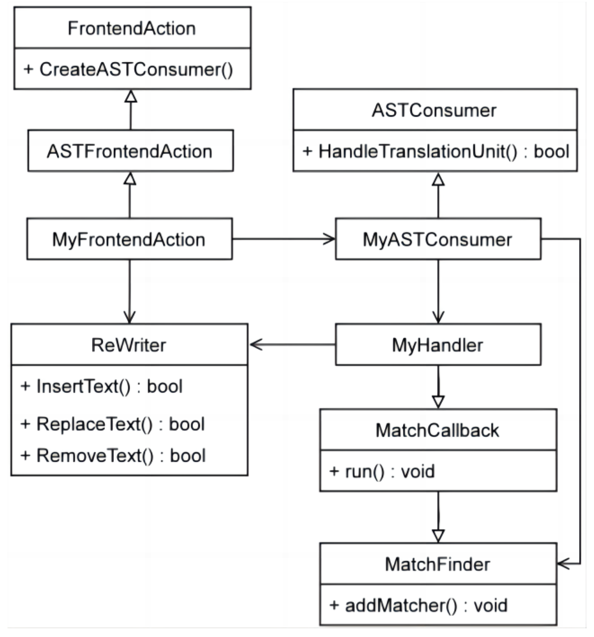
Code written using AST Matcher is more streamlined and has higher readability; the matching logic is also more natural. Therefore, in this study, we chose the AST Matcher method for node matching. The class diagram of node matching and code instrumentation using the AST Matcher method used in this study is shown in
Figure 6. There are three core classes. The MyFrontendAction class is obtained by inheriting ASTFrontendAction, the MyASTConsumer object is created by the CreateASTConsumer method of the parent class, and the Member variable of the Rewriter class is declared. MyASTConsumer inherits from the ASTConsumer class and uses the HandleTranslationUnit method to obtain translation units. At the same time, it is declared that the Member variable of the MatchFinder class is used to match the insertion position and the Member variable of the MyHandler class is used for code insertion. The MyHandler class inherits from the MatchCallback class and processes the position matched by the MatchFinder object by calling the parent class run method.
5.2.2. Implementation of Pile Insertion Action
In the previous section, the matching of the target nodes has been achieved and their positions in the AST have been found. Now, they must be staked. Clang’s Rewriter class provides the ability to add, delete, and replace source code, making it possible for code instrumentation and refactoring. When using the AST Matcher method, matching and processing nodes often occur in pairs. A matcher is added through addMatcher in the AST Consumer to find the desired node. At the same time, developers need to derive their own ASTNodeHandler from the MatchFinder:: MatchCallback class, override the run method of the parent class, and implement node processing.
Taking the Func. c file as an example, the definition and call section of the Func1 function have been successfully matched in the previous section. Next, we will intercept it through instrumentation. The main process is to generate a new interceptor function, with “new_” added before the original function name to indicate that it is a newly generated interceptor function. The parameters of the interceptor function need to include all the parameters of the original function and the Function pointer of the original function so that the original function can be called inside the interceptor function. The function body of the interception function is divided into three parts: The first part is the before part of the instrumentation requirement file. The second part is the call to the original function. If the original function has a return value, a temporary variable will be used to temporarily store its return value and it will be returned at the end of the intercepting function. The third part is the after section of the instrumentation requirements document. At the same time, all calls to the original function in the source code need to be replaced by calls to the interceptor function and the Function pointer of the original function needs to be passed as a parameter to the interceptor function.
6. Experimental Analysis
6.1. Experiment Settings
The object under test in this paper is a certain type of digital drone, which includes drone code and console code. The basic attributes of the drone can be set to simulate different flight tasks, such as airport altitude, drone weight, and flight path. The drone system fault mode database contains many types of faults. We select four fault categories of fault to test in this experimental study, with each category representing a safety attribute. The categories are common attribute faults, an abnormal state, external interference, and combined faults. The common attribute experiment tests whether the drones can follow the flight plan to fly, that is, whether it can enter the specified flight stage within the specified time range and maintain its flight state. The abnormal state experiment tests whether some of the drone sensors are abnormal, which may be due to component failure or vulnerability attack. The external interference experiment tests whether the signals received by some sensors of the drones are affected by external interference, which would lead to abnormal sensor data. The combined faults experiment is a comprehensive experiment that considers multiple safety-requirement-triggering conditions. These four safety attributes are translated into LTL formulas and then implemented as monitors to analyze the characteristics of the drone during each flight cycle. Upon completion of the flight, sensor data and monitor status throughout the flight are displayed in graphical form, with time on the horizontal axis and sensor data or monitor status on the vertical axis.
6.2. Extraction of Drone Safety Requirements
Before monitoring a drone flight, it is necessary to first extract the safety requirements related to the drone, namely, the conditions and states that the drone should satisfy during operation. This study is based on using the fault mode database to extract safety requirements related to drone functionality. In this study, we summarize the power, electrical, power system, engine, communication link, and other aspects closely related to the safety of unmanned aerial vehicles during the ground start, takeoff, and flight stages. A total of 26 categories and about 80 safety requirements are proposed and corresponding safety requirement formulas are written. Due to space limitations,
Table 10 only lists some typical safety requirements that affect drone safety.
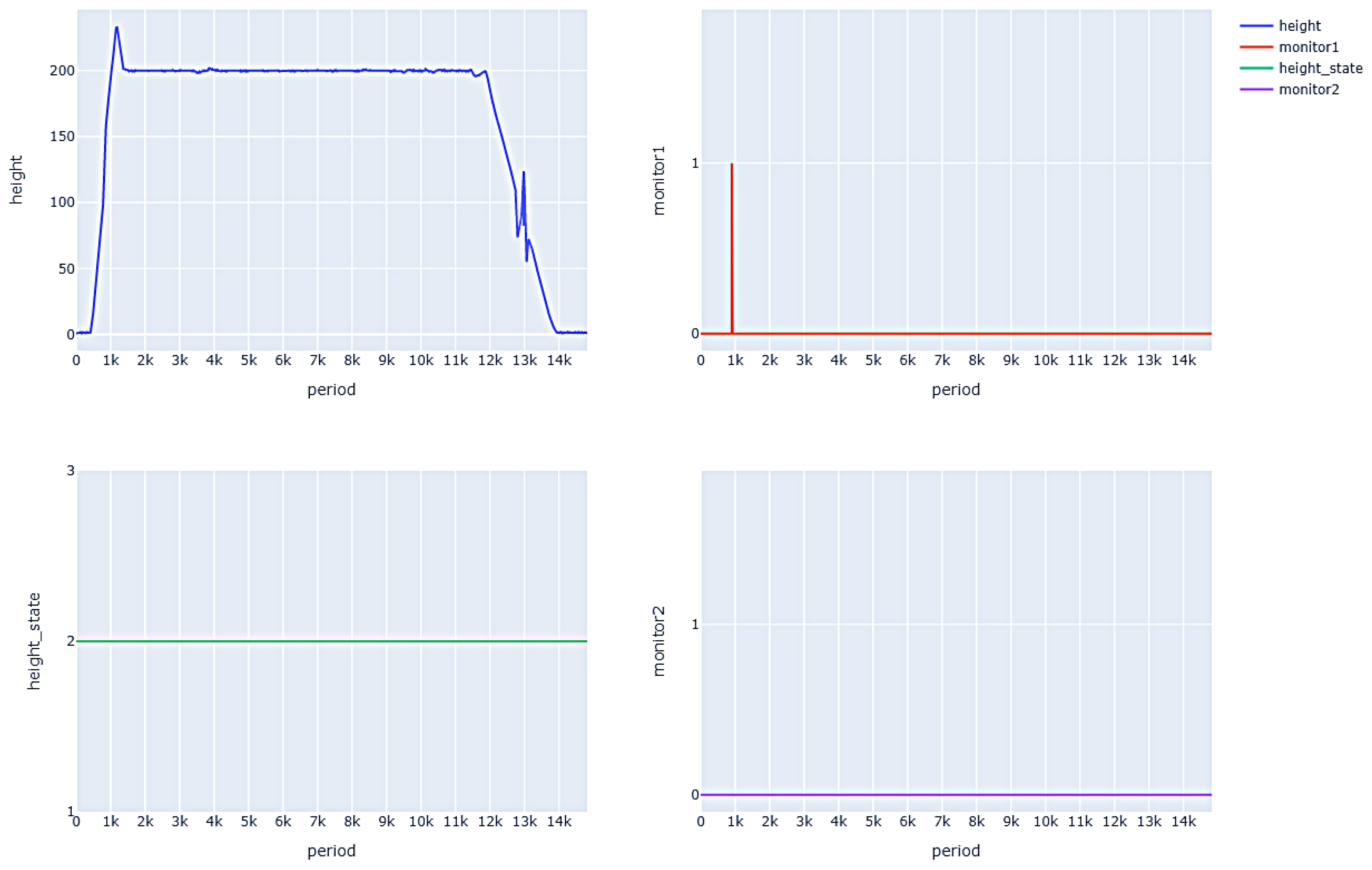
Some common attributes of the drone need to be changed to ensure that the drone can fly safely and complete its mission successfully. Therefore, in this study, we define some protocols to detect whether the drone is flying normally according to the expected plan. Taking the altitude data as an example, the safety attribute is defined. After taking off, the drones should reach the flight height of 200 m within 900 cycles and keep to this altitude within the range of (195,205) m for the rest of the flight until the flight state becomes “descending”. In addition, another highly related safety requirement is tested simultaneously. When the altitude of the drone is less than 300 m, the radio altimeter must be activated and remain active (altitude status value is 2). The formal formula is as follows.
Figure 7 shows the altitude data, altimeter status, and monitor results during a common attributes test flight. As can be seen, the drone did not reach a height of 200 m after 900 cycles and the monitor detected an anomaly (setting the result to 1). Then, during the level flight phase, the altitude of the drone remained around 200 m, so the monitor did not detect any abnormalities. The drone remained at an altitude of less than 300 m during flight, so the radio altimeter remained active and met safety requirements. The monitor did not detect any abnormalities.
6.3. Abnormal State Experiment
During the operation of drones, they may encounter some abnormal situations, including internal component failures or machine vulnerabilities that are exploited by a hostile actor and maliciously attacked, resulting in unexpected results in the range or trend of drone sensor data, leading to abnormal flight status and ultimately to the drone crashing.
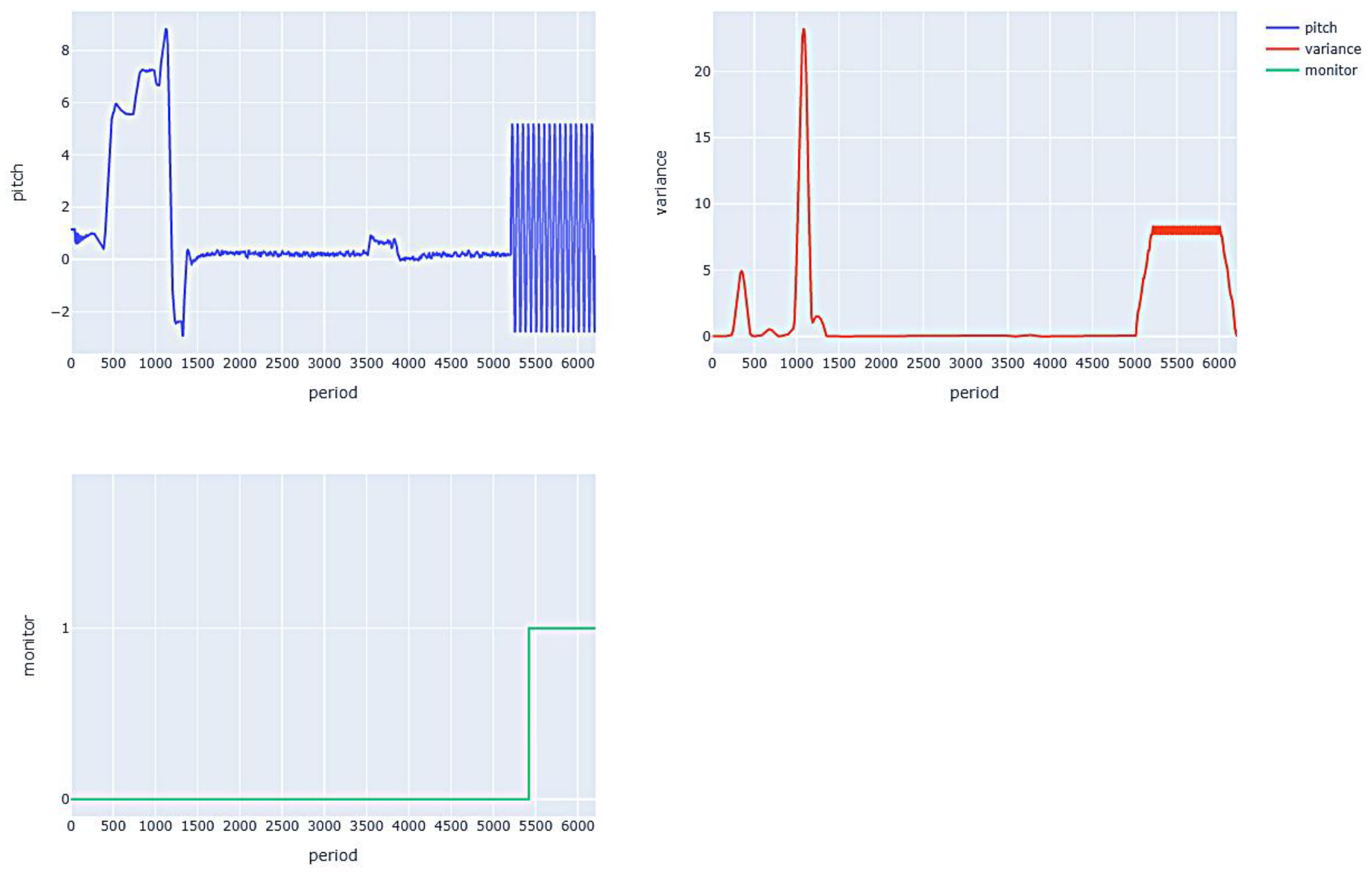
The drone obtains altitude data through altitude sensors. If the sensor malfunctions or is subjected to external attacks (attackers constantly send incorrect altitude data to the drone, causing it to make incorrect judgments about the current altitude), the drone will continuously adjust its pitch angle to achieve the desired altitude. Therefore, this experiment detects whether the drone is experiencing abnormal conditions by determining the fluctuation of the drone’s pitch angle. The safety attributes are defined as, when the drone is in level flight, the variance of the pitch angle data for the first 300 cycles ending with the current cycle must be calculated and its value should not continue to exceed 5. The formal formula is as follows.
Figure 8 shows the pitch angle data, variance, and monitor detection results during the flight. It can be seen that the pitch angle oscillates at about 5000 cycles, its variance exceeds 5 at about 5100 cycles, and the monitor value detects an abnormal situation after the pitch angle variance is greater than 5 for 300 consecutive cycles.
6.4. External Interference Experiment
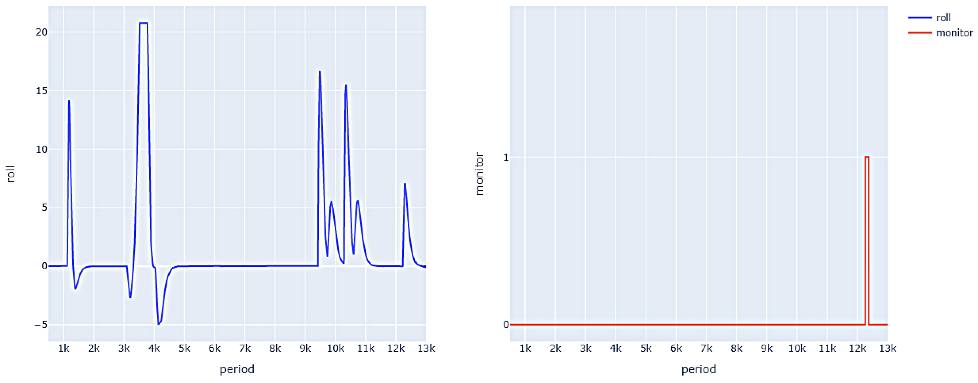
Currently, under normal circumstances, many drones will use GPS navigation to locate their position to realize flight path planning and control. Therefore, the flight process of drones is closely related to GPS data. If the GPS signal is interfered with, the normal flight of drones will be affected. The use of GPS decoys is a type of attack that interferes with the normal flight of drones by preventing them from receiving real GPS signals and making them receive false GPS signals. A jammer intercepts the real GPS signal and emits many false GPS signals. Since a drone always selects GPS signals from the strongest source, the real signal can be drowned in noise if the fake signal from the jammer is strong enough. So the drone can only receive false signals, which indirectly control the drone’s navigation system and trick the drone into flying to the wrong place. If the drone deviates from its normal course, its roll angle changes, so roll angle data can be analyzed to detect GPS jamming attacks. In this experiment, several positioning points are set for the drone. After the drone reaches the positioning point in a straight flight, it will turn and after the direction is adjusted, it will fly in a straight line again to the next positioning point.
A drone’s GPS receiver is vulnerable to external attack, but other sensors such as gyroscopes, levels, and barometric altimeters are generally difficult to attack. Changes in gyroscope roll can determine when a drone veers off course after a GPS decoy attack. Since the roll angle of the drone will not change greatly when it flies along a straight line, it will change only when it turns to the navigation point after some time. Therefore, the following safety attributes are defined. When the drone is flying, it will be given 1000 cycles to adjust the direction after reaching a navigation point. Then the absolute value of the roll angle of the drones shall be less than 5 until it reaches the next anchor point. The formal formula is shown as follows:
Figure 9 shows the roll angle data and monitor detection results during the flight process, with four positioning points reaching approximately 1000, 3000, 9000, and 10,000 cycles. It can be seen that, in the interval between the drone reaching the positioning point for 1000 cycles and reaching the next positioning point, when the absolute value of the roll angle is greater than 5 (approximately over 12,000 cycles), the monitor detects an abnormal situation. When the absolute value of the roll angle is less than 5, the monitor returns to normal.
6.5. Combined Faults Experiment
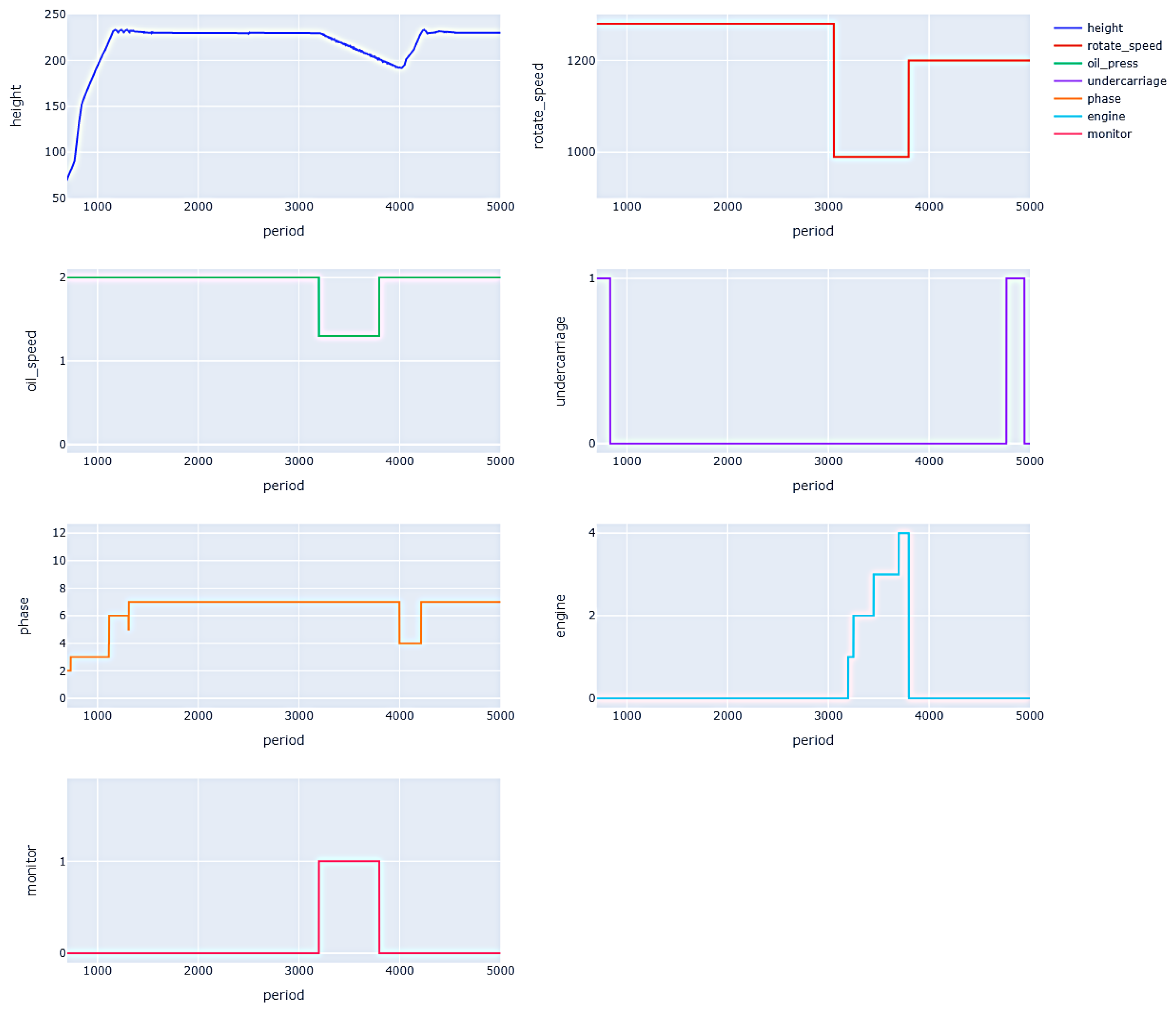
During the flight of unmanned aerial vehicles, some changes in safety status cannot be judged by a single condition, but require the monitoring of a combination of multiple conditions and the corresponding safety requirements are also composed of multiple events. For example, the following safety requirements exist to determine whether the drones can normally enter the air stop state when the conditions are met:
- (1)
The speed is less than 1000 RPM;
- (2)
The lubricating oil pressure is less than 1.5 bar;
- (3)
The landing gear is in a compressed state;
- (4)
Flight altitude greater than 60 m;
- (5)
The flight phase is not a ground hold.
When all the above conditions are met simultaneously, then
- (1)
Judge the engine’s air stop;
- (2)
When the flight phase is before glide down 1, place a falling flag.
The corresponding security requirement formula is:
Figure 10 shows the values of various attributes and monitor results in the air parking monitoring experiment. From the graph, it can be seen that for around 3000 cycles, the data of the preconditions met the requirements for air parking. At this time, the value of the engine status changed to 1 (air parking sign), but the value during the flight phase did not change to 13 (falling sign). Therefore, the monitor discovered an abnormal situation. Subsequently, the engine was restarted and after the successful restart, the engine status returned to normal. The preconditions were no longer met and the monitor returned to normal.


