Article

A GPS-Adaptive Spoofing Detection Method for the Small UAV Cluster

1
Cyberspace Security Academy, Information Engineering University, Zhengzhou 450001, China
2
Information Security Research Center, Harbin Engineering University, Harbin 150000, China
3
National Key Laboratory of Science and Technology on Information System Security, Systems Engineering Institute, Beijing 100000, China
*
Author to whom correspondence should be addressed.
Drones 2023, 7(7), 461; https://doi.org/10.3390/drones7070461
Submission received: 28 April 2023 / Revised: 16 May 2023 / Accepted: 29 May 2023 / Published: 11 July 2023
(This article belongs to the Special Issue Intelligent Coordination of UAV Swarm Systems)

Abstract

:
The small UAV (unmanned aerial vehicle) cluster has become an important trend in the development of UAVs because it has the advantages of being unmanned, having a small size and low cost, and ability to complete many collaborative tasks. Meanwhile, the problem of GPS spoofing attacks faced by submachines has become an urgent security problem for the UAV cluster. In this paper, a GPS-adaptive spoofing detection (ASD) method based on UAV cluster cooperative positioning is proposed to solve the above problem. The specific technical scheme mainly includes two detection mechanisms: the GPS spoofing signal detection (SSD) mechanism based on cluster cooperative positioning and the relative security machine optimal marking (RSOM) mechanism. The SSD mechanism starts when the cluster enters the task state, and it can detect all threats to the cluster caused by one GPS signal spoofing source in the task environment; when the function range of the mechanism is exceeded, that is, there is more than one spoofing source and more than one UAV is attacked by different spoofing sources, the RSOM mechanism is triggered. The ASD algorithm proposed in this work can detect spoofing in a variety of complex GPS spoofing threat environments and is able to ensure the cluster formation and task completion. Moreover, it has the advantages of a lightweight calculation level, strong applicability, and high real-time performance.

1. Introduction

The term unmanned aerial vehicle (UAV for short) refers to an unmanned aircraft operated by radio remote control equipment and self-contained program control device, which can provide services in places that are difficult for humans to reach. In the early stage, the application of UAVs was limited to the military field. In recent years, with the rapid improvement of sensing, remote sensing, flight control, computational vision, image transmission, and other related technologies, the development of UAV has entered the fast lane [1]. Especially since 2015, with the continuous improvement of civil UAV technology, its application in agriculture, forestry and plant protection, power inspection, geographic mapping, aerial photography, and other aspects has become more and more normal. After 2019, UAV autonomous control and application technology has made great progress, showing some new development trends. Because a single UAV can only carry a single mission load and has limited mission execution capacity, the efficiency of the whole system can be improved through the complementary ability and action coordination of multiple UAVs. Therefore, the application of UAVs is gradually developing from a single platform to multiple platforms [2].
By learning from the self-organization mechanism of nature, UAV cluster consisting of multiple UAVs with limited autonomous ability is able to achieve an overall performance gain through mutual information communication without relying on centralized command and control. As a result, UAV cluster often possesses a higher degree of autonomous cooperation and requires little human intervention to complete the expected task objectives [3].
The wide application of UAV in different fields exacerbates its security issues, e.g., network attack [4], channel attack [5], and signal attack [6]. Among these attacks, GPS spoofing as a kind of signal attack has been the most urgent threat [7,8], given the fact that modern UAV positioning and navigation systems have become highly dependent on GPS signals. If the positioning and navigation information has been deceived, UAVs may deviate from the normal flight route and in more serious cases end up in a catastrophic crash.

1.1. Problem Statement

Detecting a GPS spoofing attack is a challenging problem. In a confrontation environment, the adversary usually causes a more complex and bad impact on the cluster by deploying more spoofing sources. According to how many spoofing sources there are, the possible GPS spoofing attach faced by an UAV cluster can be divided into two categories: the single GPS spoofing source attack and the multiple GPS spoofing source attack, different deployment strategies have different effects on clusters. When there is only one spoofing source, it may attack only one UAV or multiple UAVs. Considering the case where only one target UAV has been attacked, although the target UAV may have the capability to detect the existence of spoofing by itself, the detection can hardly be reliable given the uncertainty of the environment. If multiple UAVs have been attacked by one spoofing sources, although the attack is obvious, it is still difficult to determine whether there is only one spoofing source or not. When there are multiple spoofing sources, the problem becomes even more challenging due to the complicated interactions of the spoofing sources.

1.2. Contribution

In this work, we aim at solving the GPS spoofing detection problem for the case of multiple spoofing sources and we propose a cluster cooperative positioning-based algorithm that can successfully detect the existence of spoofing for UAV clusters, no matter how complex the threat environment is. The algorithm includes two mechanisms. Under the guidance of distributed computing, we design the GPS spoofing signal detection (SSD) mechanism. Furthermore, “no longer considering who is cheated, we should pay attention to who is safe”, which is the core of the relative security machine optimal marking (RSOM) mechanism. Thus, it is worth mentioning that in order to ensure the autonomous recovery of the formation in an unsafe environment, we assume that not all members of the UAV cluster are deceived and at least one UAV in the cluster is safe. The main contributions of this paper can be summarized as follows:
  • The GPS spoofing attacks for the UAV cluster are analyzed and classified, and the various complex attack scenarios under a cluster environment are simulated. To the best of our knowledge, research into the problem of spoofing attacks on the UAV cluster from multiple spoofing sources, as considered in this paper, is novel.
  • A novel GPS-adaptive spoofing detection (ASD) algorithm which includes two detection mechanisms, GPS Spoofing Signal detection (SSD) mechanism and Relative Security UAV Optimal Marking (RSOM) mechanism, is proposed. The algorithm can switch between different detection mechanisms to effectively detect GPS spoofing signals according to the characteristics of GPS spoofing attack initiated by the attacker in different attack scenarios.
  • A modeling and hardware simulation based technique has been studied to ensure the mission safety of UAV cluster. In fact, how to ensure the mission safety of UAV cluster in GPS spoofing environment is still in its infant stage. This work provides theoretical support and an application guidance for the development and application of this new task model.
The rest of this paper is organized as follows: Section 2 mainly summarizes the relevant research work. Section 3 discusses the establishment of the small smart UAV cluster model, the principle of the GPS spoofing attack, and its impact on the cluster task state. Section 4 introduces the detailed design of ASD. Section 5 presents the simulation experiments and compares with the latest results in the same domain. Section 6 summarizes this work and concludes with the potential impacts and prospects.

2. Related Work

As reported in [reference to the Volpe report], the U.S. Department of Transportation has performed a thorough security evaluation of civil GPS signal applications and concluded that “GPS has further penetrated into civil infrastructure. It has become an attractive target and can be used by individuals, groups or countries hostile to the United States”. Malicious attacks on GPS signals mainly include intentional interference and deception, where the consequence of deception is often considered more severe than that of intentional interference. As a result, the detection of GPS deception has become a hot topic and been investigated intensively [9,10].
Some recent research has shown that civil UAVs can be easily deceived [11,12,13]. A simple GPS spoofing attack has been successfully implemented by researchers from Los Alamos National Laboratory [10]. Later, the Iranian army has claimed that they successfully controlled an American rq-170 sentinel UAV, when it was flying about 140 miles from the border between Iran and Afghanistan [14]. In [15], the authors showed that they can deceive the UAV by sending false position data to their GPS receiver, thus misleading the UAV to crash on the sand.
Regarding the detection and response schemes for GPS deception, the work in [16] has made a complete overview of the effort on combating GPS deception and jamming. A method to further improve the detectability of false GPS spoofing signal by encrypting the signature of navigation message was proposed in [17]. An algorithm for monitoring GPS deception based on power measurement and automatic gain control behavior observation has been proposed in [18]. The effectiveness of this algorithm has been verified by using commercial GPS receivers. In [19], the authors have proposed a GPS deception detection and protection scheme, leveraging the calculation of moving variance based on Doppler offset and consistency test of PVT calculation. In [20], the authors claimed that the forged GPS deception signal could not completely cover the real GPS signal, and proposed a method to detect GPS deception in the signal tracking stage through the detection technology of its residual signal. In [8], automatic gain control is used within the GPS receiver to detect and flag potential spoofing attacks within a low computational complexity framework. Moreover, [21] proposed a technique that allows UAVs to detect GPS spoofing by using an independent ground infrastructure that continuously analyzes the contents and times of arrival of the estimated UAV positions. The proposed technique is able to detect the spoofing attacks in less than two seconds and further determine the spoofing location after 15 min of monitoring time with an accuracy of up 150 m.
Notably, some other work have studied the use of multiple receivers to detect GPS spoofing attacks [11,22,23]. In [22], the authors demonstrated the ability of detecting GPS spoofing using a dual antenna receiver. Their technique relies on observing the carrier difference between different antennas under the same oscillator. In this configuration, the attacker needs to add a transmitting antenna every time when a receiving antenna is added, which makes the attacking task more complex. In [11], multiple receivers are used to authenticate GPS signal by using the correlation between GPS signal and military GPS signal. Among these receivers, a cross check receiver is used to determine whether its GPS signal is true. The technique has been tested on stationary and mobile GPS receivers and it can effectively detect spoofing attacks. In [23], multiple independent GPS receivers are used to detect GPS spoofing attacks. This technique relies on fixing the distance between receivers and then measuring the distance between the positions reported by the receivers. Under the real GPS signal, the measured distance is similar to the previous fixed distance. However, under the GPS spoofing attack, the measured distance can be close to zero. This is because all receivers are cheated of the same false position. Currently, there are still some scholars who use machine learning methods to solve this problem. Their research focus is mainly on extracting ground features, and they are committed to how to extract the accuracy of features. Although it is equally effective in application, it does not have strong interpretability [24,25,26].
There are not many existing research results based on cluster deployment to detect deception signals and ensure the safety of drone missions. Among them, a game-based detection method for drone clusters was proposed in reference [27], which utilizes the relative position relationships of members in the cluster to effectively detect spoofing attacks. However, there are strong limitations on the size and threat scenarios of the cluster. Furthermore, a method based on task prior knowledge and formation rigid structure proposed by Liang Chen takes 8 s to achieve spoofing detection [28]. The Euclidean distance between members in a cluster calculated from different data sources in reference [29] is used to determine deception. This paper enriches threat scenarios and adversary capabilities, but has a strong dependence on security thresholds. Moreover, existing achievements all share a common problem, as they do not provide a method to determine the true position of drones or ensure the continuation of missions after detecting attacks [30]. In fact, these previous works mainly focused on detection technology and did not provide mature and effective autonomous attack mitigation or defense mechanisms.

3. System Models

3.1. The Small UAV Cluster Model

Given a set of UAVs, M, performing a common mission, each of which is equipped with a GPS receiver, a wireless communication module, and some sensors for specific applications. According to the GPS signal characteristics, we use three-dimensional (3D) data to specify their locations. Let the location of UAV m at time t be u m ( t ) = [ x m ( t ) , y m ( t ) , z m ( t ) ] T , where m N + . The UAV cluster model uses the flooding broadcast mode, which is commonly used in an ad hoc network to realize the communication between UAVs. That is, each UAV in the cluster shares the location information of all the others within the effective distance of broadcast. As shown in Figure 1, d m a x is the largest distance between UAVs in the cluster, and  e m a x is the maximum effective range of UAV broadcasting. When designing the cluster formation, the condition d m a x < e m a x ensures that each UAV in the cluster can receive the location information from the other UAVs.
The relative position between UAVs is one of the key bases for the formation design. When the navigation information of an UAV is detected to be dishonest, its position can be obtained through the relative positions between the other UAVs. Therefore, when designing the model, the relative position to the other UAVs is known to each UAV in the cluster.
  • UAV Position representation in the Cartesian coordinate system
    It is known that in the position calculation, the original output data of the GPS receiver cannot directly be used in the calculation. Instead, it needs to be transformed from the spherical coordinate system to the Cartesian coordinate system.
    Suppose that D is a point on the Earth’s surface and the spherical coordinate of D is ( l a t , l o n , r ) , where r is the radius of the earth. It is shown in Figure 2 that A O B = l a t , D O B = l o n , and the point D is expressed as follows:
    D = x D y D z D = r r · c o s ( l o n ) · s i n ( l a t ) r · s i n ( l o n ) r · c o s ( l o n ) · c o s ( l a t )
    If an UAV in the cluster reaches the specified position at H, which is vertically above point D, then it broadcasts the position D :
    D = x D y D z D = r ( r + H ) · c o s ( l o n ) · s i n ( l a t ) ( r + H ) · s i n ( l o n ) ( r + H ) · c o s ( l o n ) · c o s ( l a t )
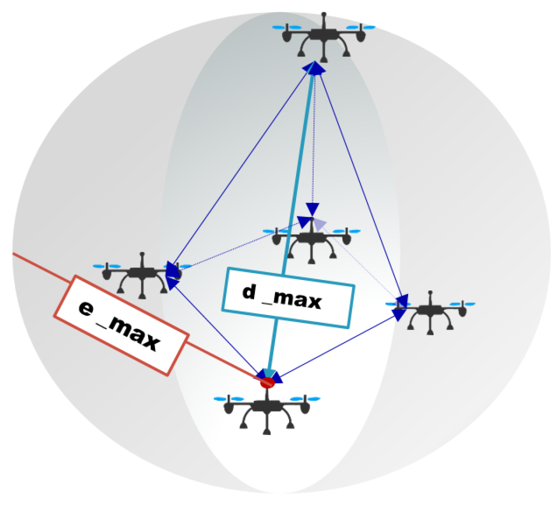
  • Indication of the relative position between UAVs
    The object of formation design is mainly to achieve a small cluster of UAVs. Thus, the full connection mode is adopted for the information interaction between UAVs. For model M = { m N + | u 1 , u 2 , u 3 , , u m } , as shown in Figure 3, the position relationship between any two UAVs can be expressed as a four-dimensional vector:
    u 1 u 2 = α β θ l
    Thus, if  u 1 = { x 1 , y 1 , z 1 } , the following equation holds:
    u 2 = x 2 y 2 z 2 = x 1 + l c o s α y 1 + l c o s β z 1 + l c o s θ

3.2. Adversary Model: GPS Spoofing Principle

The principle of GPS spoofing on the target UAV is as follows: the position spoofing attack will not change the UAV’s position, but change the UAV’s belief in its position. Thus, while the UAV is still in its real position when attacked, the perception of its location by its navigation system will be given by the attacker. Then, the UAV plans its route to the final destination according to the instructions transmitted to the controller by the navigation cognition.
The purpose of a GPS spoofer is to control the GPS antenna, in order to send the customized GPS positioning information to make the UAV navigation system believe that it is deceiving the expected position. According to the concealment and strategy of the attack, GPS spoofing attacks can be divided into the following two categories.
  • Public: the spoofer does not try to cover up the attack, no matter whether the change between the customized deceptive GPS positioning information and the real GPS positioning information is within a reasonable range. It only tries to capture the target faster.
  • Covert: the spoofer tries to avoid detection by sending cleverly crafted deceptive signals that match the actual signal in terms of output power and other parameters. Thus, the spoofer can prevent the target from triggering a fault detection alarm.
Since the spoofer can attack the target publicly or covertly, we consider that UAV is equipped with a fault detector, which can filter out the navigation signal with large mutations. Therefore, for the spoofer design, we would like to keep its attack covert by adjusting the parameters of the forged GPS signal, in order to avoid being found. The specific setting rules for parameter requirements can be found in [31]. The main idea is that the change between the spoofing signal sent by the spoofer and the signal received by the UAV GPS receiver at the previous time will be limited to a threshold, so that these applied positions will not trigger the fault detector in the UAV. Such a threshold between the current position and the position where the spoofing is applied is called the instance drift distance [32,33].
Let E m a x be the instance drifted distance that limits the attack, x m ^ ( t ) = [ x m ^ ( t ) , y m ^ ( t ) , z m ^ ( t ) ] T be the attacker’s imposed location on UAV m, and E m ( t ) = [ E x m ( t ) , E y m ( t ) , E z m ( t ) ] T be a vector whose individual elements represent the distance difference between the UAV’s actual location and the attacker’s imposed location. Then, we have the following equation:
E m ( t ) 2 = x m ( t ) x m ^ ( t ) 2 E m a x
Explanations of all variables mentioned in this section are summarized in Table 1.

4. Proposed Method

In this section, the ASD method based on UAV cluster cooperative positioning is proposed, The workflow description is detailed in the Appendix A, which includes two detection mechanisms: the SSD mechanism based on the cluster cooperative positioning and the RSOM mechanism.

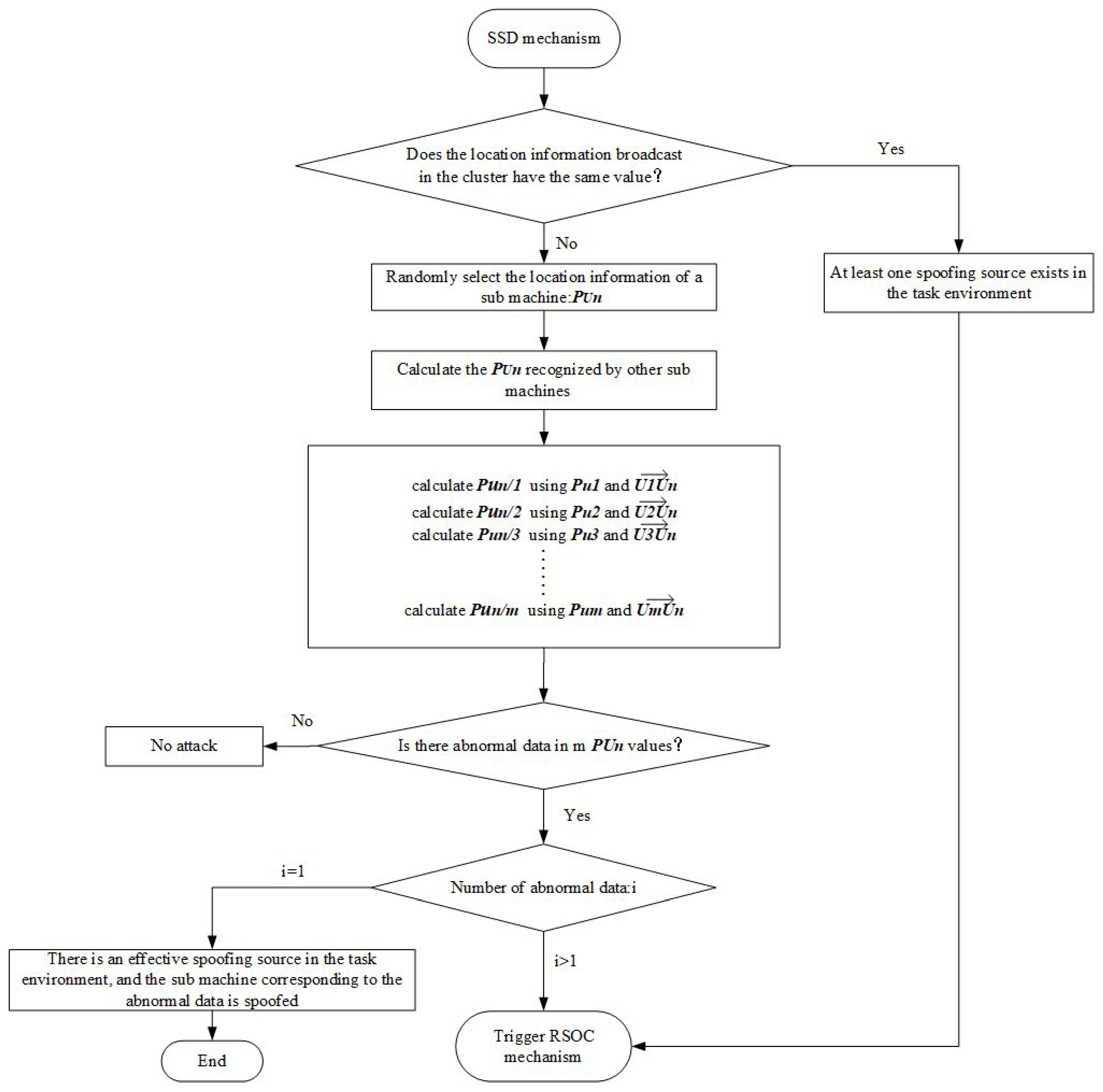
4.1. SSD Mechanism Based on Cluster Cooperative Positioning
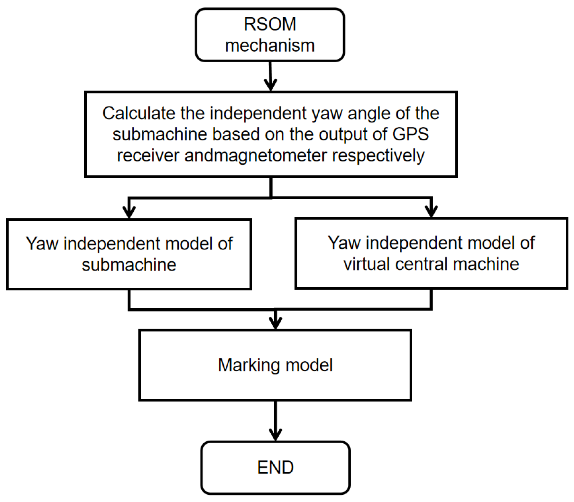
During the execution of public tasks by the UAV cluster N, all members of the cluster broadcast the real-time position obtained by GPS receiver to the team through their respective wireless communication module at each time. The design principle of SSD is: at each broadcast time, when the signals broadcast by the cluster have the same location information, one can determine that there is at least one spoofing source in the mission airspace, and the RSOM mechanism of the ASD algorithm is triggered at this time; when the broadcast signals are different, we randomly select a submachine in the cluster, U n , and extract its location information, P U n . Then, we use the real-time location information broadcasted by other members and the relative location information between other members and U n in the formation to calculate where the other members think U n should be. For example, based on the location information broadcasted by U 1 , the position where U 1 thinks U n should be located can be obtained by Formulas (2)–(4). If there is only one spoofing source in the mission airspace, the SSD mechanism can accurately locate the spoofing attack submachine in the cluster; otherwise, the RSOM mechanism will be triggered. Figure 4 shows the workflow of the SSD mechanism.

4.2. RSOM Mechanism

The RSOM mechanism is triggered when there are multiple spoofing sources in the mission airspace and the GPS signal security status of each submachine in the cluster cannot be accurately determined. Compared to the assumption of [27], i.e.,  “at least one UAV in the cluster is safe”, our RSOM can detect the case of a full cluster spoof. However, this assumption is still followed in our designed algorithm. Our purpose in doing so differs from that of [27] in that their spoofing detection has to be implemented under this assumption, whereas we do so to guarantee that the UAV cluster has the ability to recover autonomously in case of a spoofing attack. By letting go of this restriction, RSOM can call the ground station to achieve an artificial takeover of the cluster mission in the event of a full overrun being detected. In this attack scenario, in order to ensure the self-recovery capability of the cluster, the premise of RSOM is that at least one aircraft in the cluster is safe. Therefore, the threats faced by the UAV cluster can be summarized as follows: if two or more UAVs are attacked by different GPS spoofing signals, how can they be detected?
RSOM is designed with the idea that there is no need to face this problem directly. Specifically, at least one aircraft in the cluster is safe, so in such a complex threat scenario, we should accurately find the safe one. The details of the design idea are as follows: RSOM selects a virtual central machine for the UAV cluster to provide us with reference information representing the motion state of the whole cluster. Considering the loose coupling between the GPS measurement and the strapdown inertial navigation system (INS), the altitude dynamics of UAVs will not be affected by GPS spoofing attacks at the fist moment of spoofing, which has been confirmed by Kerns et al. [34] through a field test. At the same time, a large number of studies have shown that the relative controllability of altitude dynamics can maximize the asymptotic stability of closed-loop systems when applying optimal control signals in the event of GPS failure. Therefore, in the RSOM mechanism, the optimal marking of relative security machine is realized by using the deviation of the altitude information obtained by each member of UAV cluster from the GPS relative to the flight altitude obtained by altitude dynamics of the virtual central machine. In the RSOM mechanism, the yaw information is the core factor in determining the altitude of the UAV, so we simplify and divide the altitude model of the UAV, and finally, obtain the independent yaw model.
The RSOM mechanism includes three altitude models: the independent yaw model of the submachine, the independent yaw model of the virtual central machine, and the marking model. The workflow of the RSOM mechanism is shown in Figure 5.
For each UAV, the yaw angle is given by the GPS receiver and the magnetometer, which are expressed as ψ G P S and ψ m a g , the obtain algorithm are shown as Algorithm 1 and Algorithm 2, respectively [35].
Algorithm 1 Algorithm for obtaining obtain ψ G P S based on GPS receiver input data
1:
Input the position information of the current time and the previous time: ( l a t 1 , l o n 1 , a l t 1 ) and ( l a t 2 , l o n 2 , a l t 2 ) ;
2:
Take ( l a t 2 , l o n 2 , a l t 2 ) as the representation of a Cartesian coordinate system: ( x 2 , y 2 , z 2 ) ;
3:
Based on ( l a t 1 , l o n 1 , a l t 1 ) , take ( x 2 , y 2 , z 2 ) as the representation of a ENU system: ( d e 2 , d n 2 , d u 2 ) ;
4:
Constraint ψ G P S ∈[− π , π ];
5:
ψ G P S = a r c t a n 2 ( d e 2 , d n 2 ) ;
Algorithm 2 Algorithm for obtaining the ψ m a g based on magnetometer attitude measurement data
1:
Suppose that the measured value of the magnetometer in the body coordinate system, ( x b , y b , z b ) , is b m m = [ m x b m y b m z b ] T
2:
Considering that the magnetometer may not be placed horizontally during the UAV mission, it is necessary to use the two axis inclination sensors to measure the pitch angle, θ , and the roll angle, ϕ , and then project the measured values on the horizontal plane. Therefore, m ¯ x e = m x b c o s θ m + m y b s i n ϕ m s i n θ m + m z b c o s ϕ m s i n θ m m ¯ y e = m y b c o s ϕ m m z b s i n ϕ m
where m ¯ x e , m ¯ y e R indicates the projection of the magnetometer reading on the horizontal plane.
3:
Constraint ψ m a g ∈[− π , π ]
4:
ψ m a g = arctan2( m ¯ y e , m ¯ x e )
  • Independent yaw model of the submachine
    In the independent yaw model of submachine, the yaw angle of the submachine in the cluster is defined as:
    ψ = ( 1 μ ψ ) ψ G P S + μ ψ ψ m a g
    where ψ G P S and ψ m a g can be obtained by algorithms 2 and 3. μ ψ ∈[0,1] is a weighting factor.
    The basic idea of the linear complementary filter is to use their complementary features to obtain more accurate altitude angle. In this model, the linear complementary filter [36,37,38] is only used as a known tool, so it is only briefly explained without showing the detailed reasoning process. At time k, after obtaining ψ ( k ) , the yaw angle is estimated as:
    ψ ^ ( k ) = τ τ + T s ( ψ ^ ( k 1 ) + T s ω z b ( k ) ) + T s τ + T s ψ ( k )
    where τ R + represents the time constant, T s R + represents the sampling period used by the filter, and ω z b represents the component of the angular velocity in the z direction in the earth fixed coordinate system [39]. Take τ τ + T s = 0.95 , then T s τ + T s = 0.05 . The complementary filter of the yaw angle is expressed as follows:
    ψ ^ ( k ) = 0.95 ( ψ ^ ( k 1 ) + T s ω z b ( k ) ) + 0.05 ψ ( k )
  • Independent yaw model of the virtual central machine
    GPS provides external information to the UAV. It belongs to the experimental group of this subject and needs to be verified. Therefore, we need a control group in the model. For the flight altitude estimation of the whole cluster, we only use the internal information of the UAV, namely the magnetometer. The yaw representation of the flight altitude of the whole cluster is realized by fusing the yaw altitude of each member machine with a weighted average method to form a new yaw altitude model. It can be considered that we have selected a virtual central machine for the cluster, and the new yaw altitude model is the yaw representation of the virtual central machine; its physical meaning is to represent the flight altitude of the cluster to the greatest extent.
    Here:
    ψ = ψ m a g .
    Input ψ ( k ) to Equations (7) and (8) to obtain ψ ^ ( k ) . Then, the independent yaw model of the virtual central machine, Ψ ( k ) , can be expressed as follows:
    Ψ ( k ) = n = 1 m ψ n ( k ) ρ n ( k ) ρ ( k ) = 1 2 l o g 1 ε ( k ) ε ( k )
    where ε ( k ) is the error confidence obtained by the exponential standardization of the s o f t m a x function to the current error of each submachine magnetometer, and ε 1 ( k ) + ε 2 ( k ) + ε 3 ( k ) + + ε m ( k ) = 1 . ρ ( k ) is the final weight coefficient of each submachine.
  • Marking model
    The difference between the results of the independent yaw model of the virtual central machine and that of the submachine is used as the basis for the results of the calibration model:
    d n = | Ψ ( k ) ψ ^ n ( k ) |
    Note that d m i n = ( d 1 , d 2 , , d m ) , d m i n corresponding to the submachine is the optimal marking of the making model to the relative security of the UAV.

4.3. Time Complexity Analysis

According to the big O representation, O ( n ) , the algorithm grows as the data size n increases. The ASD algorithm designed in this paper does not contain loops and recursive statements, so the time complexity is O ( 1 ) . It should be noted that it does not fully represent the actual execution time. The actual execution time of the algorithm is also closely related to the performance of the hardware device.
To sum up, it can be concluded that the two mechanisms of the ASD algorithm have a serial relationship in the working process. Last, but not least, at the end of the algorithm design, we added a straightforward defense, the “Leader-follower mode”. This mode is triggered when the ASD algorithm detects GPS spoofing. That is, the relatively safe submachine selected by RSOM will enter the leader mode and the other submachines will enter the follower mode. Generally speaking, under the premise that “at least one submachine in the cluster is safe”, the ASD algorithm can solve various threats faced by UAV cluster in the mission environment, and has the ability to guarantee the formation and flight mission at the same time. This study proposes the constraint that “at least one submachine in the cluster is safe”, and its application background is the fully autonomous task of the UAV cluster. With manual monitoring and intervention during the task, this restriction can be released and the cluster submachines can be switched to manual takeover when all of them are under attack.

5. Simulation and Evaluation

To verify the effectiveness of the ASD algorithm proposed in this paper, simulation experiments are carried out in this section. The experiments are performed on Gazebo and MATLAB platforms. We built the UAV cluster system model on the Gazebo platform, and connected the MATLAB-based ASD algorithm to the Gazebo flight control through cross-platform combination. The verification process and result analysis are as follows.

5.1. Experimental Configuration

In this experiment, during the task of the UAV cluster system model, the motion heights of all submachines are always the same, and the subsequent spoofing signal generation is only also based on longitude and latitude. Therefore, when designing the formation, β = 0 and θ = 0 are in the relative position relationship between the cluster submachines, and the overall structure is a pentagon. The specific motion parameters of the small smart UAV cluster after entering the stable flight are as follows:
  • Cluster size: 5;
  • Relative position relationship between machines: [ α β θ l];
  • Cluster velocity: 5 m/s;
  • Cluster motion height: 50 m;
  • Cluster motion direction: all submachines are consistent;
  • Maximum distance between machines: 20 m;
  • Maximum effective range of communication: 500 Hz.
Correspondingly, to verify the detection efficiency of the ASD algorithm proposed in this study, we modeled the enemy according to the GPS spoofing principle on the Gazebo simulation platform. Five spoofing sources (S1, S2, S3, S4, S5) are set up; following the movement of the cluster, they are randomly distributed around the cluster and the distance from the cluster is always within the effective range of the spoofing signal. Section 3.2 mentions both public and covert spoofing, but the detection principle of the ASD proposed does not specifically target a certain type of spoofing. However, in the experimental deployment, the enemy models all used covert deception, as it is a more advanced spoofing ability.

5.2. Experimental Deployment

The initial state of the UAV cluster system model at the beginning of each scenario: the submachines are lined up on the ground. The UAV cluster is manually controlled to take off vertically one by one, reaching a specified altitude of 50 m. The cluster then enters the fully autonomous mode. Each submachine adjusts its position according to the preset positional relationship between the aircraft, forms a formation, and enters the flight mission.
  • Scenario 1: Baseline model test: This case is to obtain the normal movement log of the UAV cluster in the mission scenario without any attack or threat, which can be used as a baseline to detect the threat later.
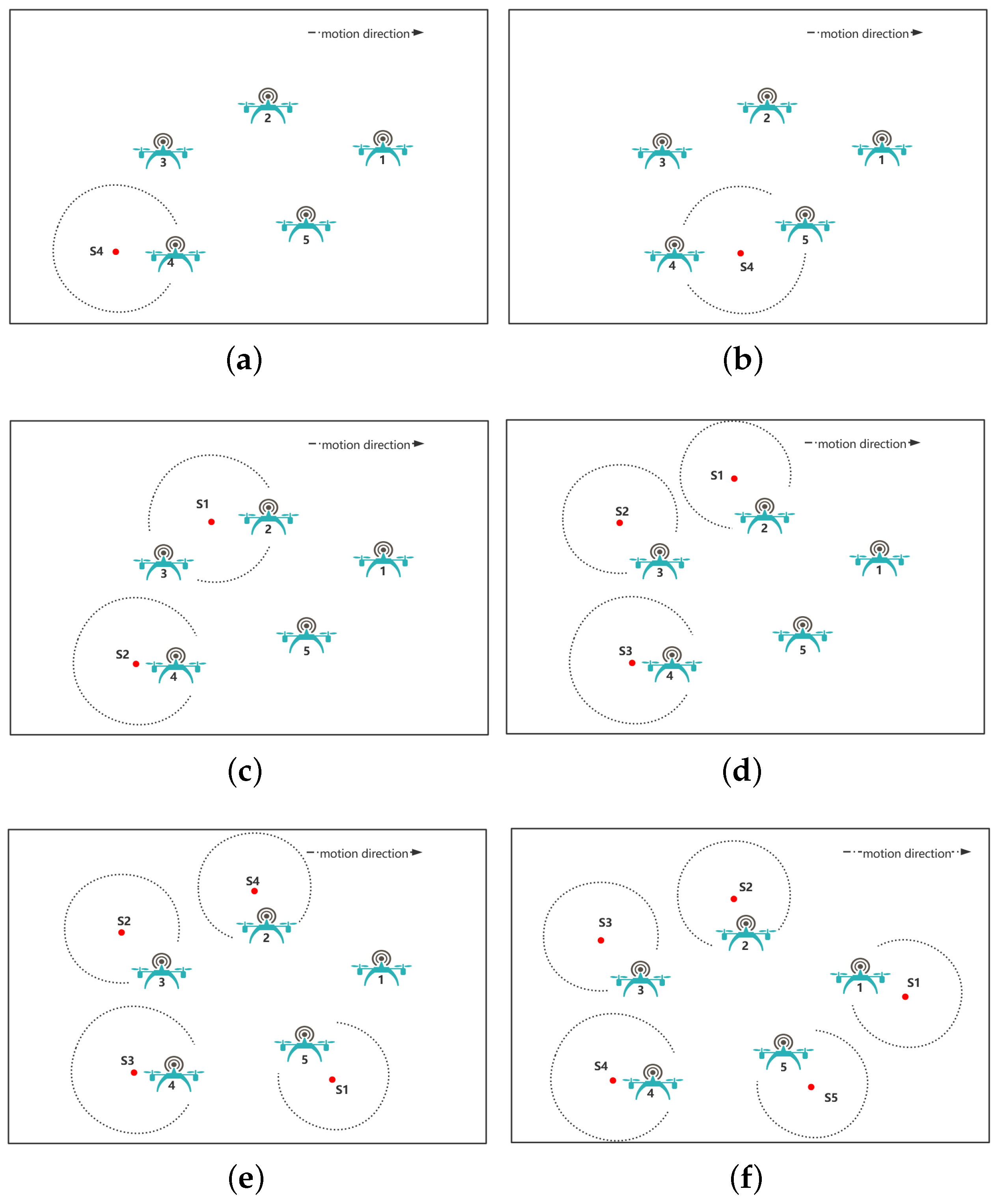
  • Scenario 2: Adversary model test: Note that the five spoofing sources work exactly the same, so only one of them is randomly selected for validity testing. In this scenario, the deployment location of S4 is shown in Figure 6. In Figure 6a, there is only one submachine in the signal radiation range of S4, while in Figure 6b, there are more submachines in its signal radiation range. Such a setup can test not only the effectiveness of the spoofing source, but also whether the spoofing source can spoof all submachines within its signal radiation range. In the experiment, after the cluster enters a stable mission state, we do not start the ASD algorithm, but we start S4, after which we observe the movement state of the cluster and save the flight logs.
  • Scenario 3: Contrast experiment of scenario 2: In this case, the deployment location of S4 is shown in Figure 6a; that is, there is only one submachine in the signal radiation range of S4. Different from the setting of scenario 2, after the cluster enters a stable mission state, we first start the ASD algorithm and then start S4. After that, we record the movement state of the cluster and save the flight logs.
  • Scenario 4: Testing of two spoofing sources: In this case, the deployment locations of the two spoofing sources (i.e., S1 and S2) are shown in Figure 6c. It can be observed from Figure 6c that the signal radiation range of these two spoofing sources contains three submachines. Here, we will use S1 and S2 to attack them. In the experiment, after the cluster enters a stable mission state, we start the ASD algorithm and turn on the two spoofing sources. Then, the movement state of the cluster and the flight logs will be recorded.
  • Scenario 5: Testing of three spoofing sources: In this case, the deployment locations of the three spoofing sources (i.e., S1, S2, and S3) are shown in Figure 6d. The rest of the operation is the same as in Scenario 4.
  • Scenario 6: Testing of four spoofing sources: In this case, the deployment locations of the three spoofing sources (i.e., S1, S2, S3, and S4) are shown in Figure 6e. The rest of the operation is the same as in Scenario 4.
  • Scenario 7: Testing of the full cluster spoofed: In this case, we directly considered and deployed the most complex attack scenario with five spoofing sources (i.e., S1, S2, S3, S4, and S5); as shown in Figure 6f, after the cluster enters a stable mission state, we start the ASD algorithm and the five spoofing sources. It can be observed that the cluster suddenly oscillates in formation after a period of time, but soon returns to its original form; however, the overall motion direction is off the expected trajectory. At that point, the UAV cluster sent a distress signal to the ground station. Again, we keep the flight logs.

5.3. Experimental Results and Analysis

Scenarios 1 and 2 of the experimental deployment belong to equipment testing and the others belong to algorithm verification.
In each scenario, we conduct multiple sets of experiments. Throughout the experiment, we observed that, in the state of cluster motion, at some point after the spoofing source was turned on, individual submachines did shake abnormally or leave the team, but the final observation result was that the cluster corrected the formation and finished the flight mission. The specific result analysis can be obtained through the retained flight logs, as shown below.
Model testing results
Figure 7a shows the state diagram of the UAV cluster system model completing a flight mission in a safe environment, i.e., scenario 1. Figure 7b,c are the results of the verification of the enemy model, i.e., scenario 2. Among them, Figure 7b shows the output of the GPS receiver deploying a spoofing source and the S4 spoofing a submachine, No. 4. Figure 7c shows the output of the GPS receiver deploying S4 to deceive two submachines, i.e., 4 and 5, simultaneously.
It can be seen that the formation of the UAV cluster has been disrupted and the output conforms to the spoofing principle. This phenomenon implies that S4 does effectively attack the submachines within its signal radiation range. Furthermore, it demonstrates that the enemy model we designed is effective, which can support the construction of the GPS spoofing countermeasure environment required for the experiment.
Algorithm verification results
Since no abnormality was observed in the overall motion state of the UAV cluster, we chose to use the data for a more intuitive interpretation. In the table recording data information, we use the same color to indicate the corresponding relationship between the spoofing source and the target. Moreover, ▸ marks the reference machine selected by ASD, while ★ marks the target selected.
Table 2 shows the record of current spoofing sources, and the flight logs of each submachine in scenario 3. According to the ASD algorithm design, the RSOM mechanism will not be triggered when only one aircraft suffers a spoofing attack. In fact, the final output of the ASD algorithm is the detection result of the SSD mechanism. According to the log information of the submachine GPS receiver, it can be seen that No. 4 was attacked; the SSD randomly selected No. 1 at this time, and only No. 4 had abnormal cognition of the position of No. 1 of the other four racks. Furthermore, we can see from the logs that after detecting a spoofing attack on No. 4, the system tells No. 4 to disable the GPS receiver and go into the leader mode in the cluster. Similarly, we can also see in the logs that the algorithm detected the threat at the second moment after being spoofed.
Table 3 shows the record of spoofing sources currently, and the flight logs for each submachine in scenario 4. Unlike Table 2, the final output of the ASD algorithm is no longer the result of the SSD mechanism, but rather RSOM. Based on the analysis of the spoofing sources data and GPS receiver information, it is not difficult to see that No. 2 and 3 were attacked by the same spoofing source, S2, and No. 4 was attacked by a different spoofing source, S1, from the previous signal. This situation cannot be solved by SSD, which triggers RSOM. In No. 1 and No. 5, which are safe in the cluster, RSOM finally chooses No. 5 as the leader of the safety machine according to the idea of algorithm design. Similarly, in scenario 5, these three submachines are also subject to a spoofing attack, the difference being that these three submachines receive spoofing signals from three different spoofing sources, respectively, which can be obtained from Table 4. The RSOM mechanism also works perfectly; it selected No. 1.
Scenario 6 is the most complicated of all. To ensure that each spoofing source deployed achieves the expected efficiency, we iteratively adjust their location and signal strength, and finally, achieve one-to-one spoofing, as shown in Table 5. Of course, scenario 6 is also the strongest proof of the effectiveness of the ASD algorithm. In our deployment, No. 1 is outside the effective range of all spoofing signals. From the table we can see that the RSOM does calibrate it accurately, making it the leader of the cluster. During the experimental observation, we saw that the formation of the UAV cluster vibrated obviously when attacking, but it quickly recovered and adjusted as before, and finally completed the task.
Table 6 shows the record of spoofing sources and the flight logs for each submachine in scenario 7. In the validation work of this scenario, we liberalized the “at least one drone safe” restriction and deployed five different spoofing sources to spoof each of the five submachines separately. As you can see from the information in Table 6, the RSOM still selected the submachine it thought could be the leader out of the five submachines: No. 2. However, the fact is that No. 2 has also been attacked by the spoofer S2. Its yaw information relative to that of the virtual central machine was already far greater than the normal drift range of the magnetometer. At this point, the UAV cluster no longer had completely reliable navigation information and the ASD eventually sent a distress command to the ground station.
From the above series of experimental results, the ASD algorithm can detect the attack behavior at the second moment of spoofing. The acquisition frequency of UAV flight logs is 5 Hz, which means that the time required to detect deception is 0.4 s. This is because the ASD algorithm contains two mechanisms, which take time to judge, trigger, and switch. From the information output frequency of the flight log, ASD is known as a very efficient real-time detection algorithm, which is not affected by the time delay of one recording. On the other hand, the RSOM mechanism does not seem to focus on detecting spoofing intuitively, but this is not the case. When a secure submachine is selected, all information it provides is trusted by default. Then, based on the geometric relationship between the submachines, it is easy to obtain the location where other submachines should be. At this time, if there is a non-negligible error between the information output by the GPS receiver of which submachine and the information provided by the secure submachine, it can be determined that the information has been spoofed. Because this problem is obvious, it is not emphasized. The “Lead-follower” mode is a small defense set up for the cluster to ensure that at least one submachine is safe to complete the task.

5.4. Comparative Analysis of the Method’s Performance

Regardless of whether used in a simulation environment or a real physical environment, it is difficult to fully reproduce the theoretical results of existing research in UAV flight experiments due to the uncertainty brought by atmospheric disturbances and motion time drift in the environment on the output of UAV sensors. Therefore, in this section, the original authors’ analysis of the original performance data of the methods proposed by them is directly referenced and compared with the methods proposed in this chapter in different performance dimensions.
Comparing the ASD method proposed in this article with the detection method proposed by Liang, Chen et al. [28] in Table 7, our method only took 0.4 s in a task, which can be called a very effective real-time detection method that is not affected by the time delay of a single record; concurrently, ASD is, without requiring prior knowledge, suitable for random flight missions and also better at detecting accuracy.
AR Eldosouky, A Ferdowsi, et al. [27], when analyzing their proposed method, did not analyze the performance of the method such as timeliness and detection accuracy. They paid more attention to the effectiveness of a simulation experiment, and their method can solve a narrow problem domain, which not only has strong limitations on the threat scenarios where deception occurs, but also specifies the applicable cluster size. By relaxing these limitations, the proposed ASD method can face complex threat scenarios with the same detection capabilities.
The method Pavlo Mykytyn (2023) [29] proposed does not limit the types of threats that occur, and also designs complex adversarial scenarios. However, the design of the method to determine whether the spoofing attack occurs based on the distance difference has a strong dependence on the security threshold, but there is currently no authoritative setting rule for the security threshold. In addition, the infrared ranging method introduces additional hardware equipment. In ASD method proposed, there is no such issue, as there is no need for auxiliary values or equipment.
Finally, the confrontation environment that ASD proposed in this chapter can face is complex, and it is worth mentioning that the ASD method does not require any prior knowledge, and the assistance of any other additional equipment and does not increase the load burden on unmanned aerial vehicles. Moreover, the ASD method has small computational complexity, has high efficiency, and is timely and accurate.

6. Conclusions

At present, in view of the impact of GPS spoofing on UAVs, the existing detection methods mainly focus on the single-machine problem. Machine learning methods are the most popular of these methods. In the practical application of UAVs, timeliness is an issue that cannot be ignored. The detection mechanism in the ASD algorithm has good detection efficiency in the simulation environment; accurate detection can be achieved almost immediately when a spoofing attack occurs. On the other hand, at present, how to solve the UAV cluster in the face of GPS spoofing attack is still a new problem. Among the few research results that address the same problem [27,29], the execution of methods requires the execution under various constraints.
Obviously, the confrontation environment faced by the ASD method proposed in this study is more complex. It is worth mentioning that the ASD method does not use any other equipment except the most basic airborne equipment, and the computation sequence is simple. In the experimental design of this article, in order to accurately grasp and analyze the objective performance of the method, atmospheric disturbance factors were not added to the simulation environment. Furthermore, the autonomous performance of ROSM mechanism is established under a constraint condition of “at least one secure drone exists in the cluster”. Thus, in the next research step, we will find problems based on practical applications, hoping to improve the robustness of ASD. In addition, in future research, we will consider using visual ranging among UAV cluster members to determine the true location of the submachines attacked by spoofing. In this way, the algorithm will become more complete and intelligent, enabling better cluster control.

Author Contributions

Conceptualization, L.M.; methodology, L.M.; validation, L.M. and L.Z.; writing—original draft preparation, L.M.; writing—review and editing, W.Y. and L.Y. All authors have read and agreed to the published version of the manuscript.

Funding

This work was supported in part by the National Natural Science Foundation of China under Grant 61831007 and 61971154 and Basic Scientific Research Projects under Grant JCKY2020604B004.

Data Availability Statement

Due to some data being classified, it cannot be made public.

Conflicts of Interest

We hereby declare that there is no conflict of interest in the research content and process of this article.

Appendix A

This is the flowchart of our proposed method, ASD, and the mechanisms description included is in the main text.
Figure A1. Flowchart: outline of the ASD’s process.
Drones 07 00461 g0a1

References

  1. Gaspar, J.; Ferreira, R.; Sebastião, P.; Souto, N. Capture of UAVs Through GPS Spoofing Using Low-Cost SDR Platforms. Wirel. Pers. Commun. 2020, 115, 2729–2754. [Google Scholar] [CrossRef]
  2. Na, Z.; Liu, Y.; Shi, J.; Liu, C.; Gao, Z. UAV-Supported Clustered NOMA for 6G-Enabled Internet of Things: Trajectory Planning and Resource Allocation. IEEE Internet Things J. 2021, 8, 15041–15048. [Google Scholar] [CrossRef]
  3. Yi, W.; Liu, Y.; Deng, Y.; Nallanathan, A. Clustered UAV Networks With Millimeter Wave Communications: A Stochastic Geometry View. IEEE Trans. Commun. 2020, 68, 4342–4357. [Google Scholar] [CrossRef]
  4. Basan, E.; Basan, A.; Nekrasov, A.; Fidge, C.; Sushkin, N.; Peskova, O. GPS-Spoofing Attack Detection Technology for UAVs Based on Kullback–Leibler divergence. Drones 2022, 6, 8. [Google Scholar] [CrossRef]
  5. Jetto, J.; Gandhiraj, R.; Sundaram, G.; Soman, K.P. Software Defined Radio-Based GPS Spoofing Attack Model on Road Navigation System. In Soft Computing and Signal Processing; Spinger: Singapore, 2022. [Google Scholar]
  6. Huang, K.W.; Wang, H.M. Combating the Control Signal Spoofing Attack in UAV Systems. IEEE Trans. Veh. Technol. 2018, 67, 7769–7773. [Google Scholar] [CrossRef]
  7. Mekdad, Y.; Aris, A.; Babun, L.; Fergougui, A.E.; Conti, M.; Lazzeretti, R.; Uluagac, A.S. A Survey on Security and Privacy Issues of UAVs. arXiv 2021, arXiv:2109.14442. [Google Scholar] [CrossRef]
  8. Akos, D.M. Who’s Afraid of the Spoofer? GPS/GNSS Spoofing Detection via Automatic Gain Control (AGC). Navigation 2012, 59, 281–290. [Google Scholar] [CrossRef]
  9. Pardhasaradhi, B.; Srihari, P.; Aparna, P. Spoofer-to-Target Association in Multi-Spoofer Multi-Target Scenario for Stealthy GPS Spoofing. IEEE Access 2021, 9, 108675–108688. [Google Scholar] [CrossRef]
  10. Manesh, M.R.; Kenney, J.; Hu, W.; Devabhaktuni, V.K.; Kaabouch, N. Detection of GPS Spoofing Attacks on Unmanned Aerial Systems. In Proceedings of the 16th IEEE Annual Consumer Communications & Networking Conference, CCNC 2019, Las Vegas, NV, USA, 11–14 January 2019; IEEE: Piscataway, NJ, USA, 2019; pp. 1–6. [Google Scholar] [CrossRef]
  11. Williamson, M. GPS Spoofing. Ph.D. Thesis, Utica College, Utica, NY, USA, 2014. [Google Scholar]
  12. She, F.; Zhang, Y.; Shi, D.; Zhou, H.; Xu, T. Enhanced Relative Localization Based on Persistent Excitation for Multi-UAVs in GPS-Denied Environments. IEEE Access 2020, 8, 148136–148148. [Google Scholar] [CrossRef]
  13. Shafique, A.; Mehmood, A.; Elhadef, M. Detecting Signal Spoofing Attack in UAVs Using Machine Learning Models. IEEE Access 2021, 9, 93803–93815. [Google Scholar] [CrossRef]
  14. Meng, L.; Yang, L.; Ren, S.; Tang, G.; Zhang, L.; Yang, F.; Yang, W. An Approach of Linear Regression-Based UAV GPS Spoofing Detection. Wirel. Commun. Mob. Comput. 2021, 2021, 5517500. [Google Scholar] [CrossRef]
  15. Bada, M.; Boubiche, D.E.; Lagraa, N.; Kerrache, C.A.; Imran, M.; Shoaib, M. A policy-based solution for the detection of colluding GPS-Spoofing attacks in FANETs. Transp. Res. Part A Policy Pract. 2021, 149, 300–318. [Google Scholar] [CrossRef]
  16. Humphreys, T.E.; Ledvina, B.M.; Psiaki, M.L.; O’Hanlon, B.W.; Kintner, P.M. Assessing the Spoofing Threat: Development of a Portable GPS Civilian Spoofer. In Proceedings of the International Technical Meeting of the Satellite Division of the Institute of Navigation, Savannah, GA, USA, 16–19 September 2008. [Google Scholar]
  17. Guenther, C. A Survey of Spoofing and Counter-Measures. Navigation 2015, 61, 159–177. [Google Scholar] [CrossRef]
  18. Manfredini, E.G.; Akos, D.M.; Chen, Y.H.; Lo, S.; Enge, P. Effective GPS Spoofing Detection Utilizing Metrics from Commercial Receivers. In Proceedings of the 2018 International Technical Meeting of the Institute of Navigation, Reston, VA, USA, 29 January–1 February 2018. [Google Scholar]
  19. Jovanovic, A.; Botteron, C.; Fariné, P.A. Multi-test Detection and Protection Algorithm Against Spoofing Attacks on GNSS Receivers. In Proceedings of the Position, Location & Navigation Symposium-Plans, IEEE/ION, Monterey, CA, USA, 5–8 May 2014. [Google Scholar]
  20. Wesson, K.; Rothlisberger, M.; Humphreys, T. Practical Cryptographic Civil GPS Signal Authentication. Navigation 2012, 59, 177–193. [Google Scholar] [CrossRef]
  21. Kai, J.; Schafer, M.; Moser, D.; Lenders, V.; Schmitt, J. Crowd-GPS-Sec: Leveraging Crowdsourcing to Detect and Localize GPS Spoofing Attacks. In Proceedings of the 2018 IEEE Symposium on Security and Privacy (SP), San Francisco, CA, USA, 20–24 May 2018. [Google Scholar]
  22. Montgomery, P.Y.; Humphreys, T.E.; Ledvina, B.M. Receiver-Autonomous Spoofing Detection: Experimental Results of a Multi-Antenna Receiver Defense Against a Portable Civil GPS Spoofer. In Proceedings of the 2009 International Technical Meeting of The Institute of Navigation, Anaheim, CA, USA, 26–28 January 2009. [Google Scholar]
  23. Jansen, K.; Tippenhauer, N.O.; Ppper, C. Multi-receiver GPS spoofing detection: Error models and realization. In Proceedings of the the 32nd Annual Conference, Los Angeles, CA, USA, 5–8 December 2016. [Google Scholar]
  24. Rao, H.; Wang, S.; Hu, X.; Tan, M.; Da, H.; Cheng, J.; Hu, B. Self-Supervised Gait Encoding with Locality-Aware Attention for Person Re-Identification. In Proceedings of the International Joint Conference on Artificial Intelligence, Yokohama, Japan, 11–17 July 2020. [Google Scholar]
  25. Xu, S.; Rao, H.; Peng, H.; Jiang, X.; Guo, Y.; Hu, X.; Hu, B. Attention-Based Multilevel Co-Occurrence Graph Convolutional LSTM for 3-D Action Recognition. IEEE Internet Things J. 2021, 8, 15990–16001. [Google Scholar] [CrossRef]
  26. Rao, H.; Xu, S.; Hu, X.; Cheng, J.; Hu, B. Augmented Skeleton Based Contrastive Action Learning with Momentum LSTM for Unsupervised Action Recognition. Inf. Sci. 2021, 569, 90–109. [Google Scholar] [CrossRef]
  27. Eldosouky, A.R.; Ferdowsi, A.; Saad, W. Drones in Distress: A Game-Theoretic Countermeasure for Protecting UAVs Against GPS Spoofing. IEEE Internet Things J. 2020, 7, 2840–2854. [Google Scholar] [CrossRef]
  28. Liang, C.; Miao, M.; Ma, J.; Yan, H.; Li, T. Detection of GPS Spoofing Attack on Unmanned Aerial Vehicle System. In Proceedings of the Machine Learning for Cyber Security: Second International Conference, ML4CS 2019, Xi’an, China, 19–21 September 2019. [Google Scholar]
  29. Mykytyn, P.; Brzozowski, M.; Dyka, Z.; Langendoerfer, P. GPS-Spoofing Attack Detection Mechanism for UAV Swarms. arXiv 2023, arXiv:2301.12766. [Google Scholar]
  30. Chen, M.; Mozaffari, M.; Saad, W.; Yin, C.; Debbah, M.; Hong, C.S. Caching in the Sky: Proactive Deployment of Cache-Enabled Unmanned Aerial Vehicles for Optimized Quality-of-Experience. IEEE J. Sel. Areas Commun. 2017, 35, 1046–1061. [Google Scholar] [CrossRef]
  31. Su, J.; He, J.; Cheng, P.; Chen, J. A Stealthy GPS Spoofing Strategy for Manipulating the Trajectory of an Unmanned Aerial Vehicle. IFAC-PapersOnLine 2016, 49, 291–296. [Google Scholar] [CrossRef]
  32. Zeng, K.C.; Shu, Y.; Liu, S.; Dou, Y.; Yang, Y. A Practical GPS Location Spoofing Attack in Road Navigation Scenario. In Proceedings of the the 18th International Workshop, Sonoma, CA, USA, 21–22 February 2017. [Google Scholar]
  33. Liu, Q.; Chen, S.; Wang, G.; Lan, Y. Drift Evaluation of a Quadrotor Unmanned Aerial Vehicle (UAV) Sprayer: Effect of Liquid Pressure and Wind Speed on Drift Potential Based on Wind Tunnel Test. Appl. Sci. 2021, 11, 7258. [Google Scholar] [CrossRef]
  34. Kerns, A.J.; Shepard, D.P.; Bhatti, J.A.; Humphreys, T.E. Unmanned Aircraft Capture and Control Via GPS Spoofing. J. Field Robot. 2014, 31, 617–636. [Google Scholar] [CrossRef]
  35. Kj, M.; Wittenmark, B. Computer-Controlled Systems: Theory and Design, 2nd ed.; Elsevier: New York, NY, USA, 1990. [Google Scholar]
  36. Wu, J.; Zhou, Z.; Fourati, H.; Li, B.; Liu, M. Generalized Linear Quaternion Complementary Filter for Attitude Estimation From Multisensor Observations: An Optimization Approach. IEEE Trans. Autom. Sci. Eng. 2019, 16, 1330–1343. [Google Scholar] [CrossRef]
  37. Kottath, R.; Narkhede, P.; Kumar, V.; Karar, V.; Poddar, S. Multiple Model Adaptive Complementary Filter for Attitude Estimation. Aerosp. Sci. Technol. 2017, 69, 574–581. [Google Scholar] [CrossRef]
  38. Yoo, T.S.; Hong, S.K.; Yoon, H.M.; Park, S. Gain-Scheduled Complementary Filter Design for a MEMS Based Attitude and Heading Reference System. Sensors 2011, 11, 3816–3830. [Google Scholar] [CrossRef] [PubMed]
  39. Kang, C.W.; Chan, G.P.; Filter, K. Attitude estimation with accelerometers and gyros using fuzzy tuned Kalman filter. In Proceedings of the 2009 European Control Conference (ECC), Budapest, Hungary, 23–26 August 2009. [Google Scholar]
Figure 1. Relationship between the largest relative distance in an UAV cluster and the maximum effective distance of flooding communication.
Drones 07 00461 g001
Figure 2. Schematic diagram of the conversion between the spherical coordinate system and ground coordinate system.
Drones 07 00461 g002
Figure 3. Schematic diagram of the relative position between UAVs in a cluster.
Drones 07 00461 g003
Figure 4. The workflow of the SSD mechanism.
Drones 07 00461 g004
Figure 5. The design and work principle of the RSOM mechanism.
Drones 07 00461 g005
Figure 6. Tactics of an adversary: deploying the deception source. (a) Deploy S4 to attack one of the submachines to verify the effectiveness of the spoofing source. (b) Verify whether the S4 spoofing source has the ability to spoof all submachines within its signal radiation range. (c) Deploy two different spoofing sources to launch a GPS spoofing signal attack on three submachines in the cluster. (d) Deploy three different spoofing sources to launch a GPS spoofing signal attack on three submachines in the cluster. (e) Deploy four different spoofing sources to attack four submachines in the cluster. (f) Deploy five different spoofing sources to attack five submachines in the cluster.
Drones 07 00461 g006
Figure 7. Illustration of effectiveness verification of the UAV cluster system model and the enemy model. (a) The trajectory information output by GPS receivers of the UAV cluster system model in the safe mission environment. (b) Deploy spoofing source 4 to attack No. 4 in the cluster without any detection and defense measures. The motion trajectory output by UAV cluster GPS receivers. (c) Deploy spoofing source 4 to attack No. 4 and 5 in the cluster without any detection and defense measures. The motion trajectory output by UAV cluster GPS receivers.
Drones 07 00461 g007
Table 1. Explanations of all variables mentioned in Section 3.
VariablesExplanation
MA set of UAVs
u m One of the members in M
d m a x The largest distance between each two UAVs in M
e m a x The maximum effective range of UAV broadcasting
DThe parking position of UAV on the ground
D The hovering position of UAV in the air
u 1 u 2 The position relationship between any two UAVs in M
E m a x The instance maximum drifted distance
Table 2. The spoofing data record and flight log information obtained by scenario 3.
Enemy deployment strategy and spoofing data record
S1S2S3S4S5
---25.5 28.2-
---27.5 29.2-
---29.5 30.2-
---31.5 31.2-
Position information received by the GPS receiver of each submachine in the cluster
No. 1No. 2No. 3No. 4No. 5
32.87953077 34.3094351130.02636122 36.3823841327.17319167 34.3094351128.26300546 30.9553331531.78971698 30.95533315
32.59085634 34.0325469129.73768679 36.1054959326.88451724 34.0325469127.97433104 30.6784449531.50104255 30.67844495
32.32634117 33.7324940429.47317162 35.8054430626.62000208 33.7324940427.5 29.231.23652738 30.37839208
32.09622408 33.40531529.24305453 35.4782640226.38988498 33.40531529.5 30.231.00641029 30.05121304
31.91688606 33.0477707829.06371651 35.120719826.21054696 33.04777078-30.82707227 29.69366881
31.81412885 32.6611948428.9609593 34.7341438626.10778976 32.66119484-30.72431506 29.30709287
Output of the SSD mechanism in the ASD algorithm under the same timestamp
▸No. 1No. 2No. 3★No. 4No. 5
32.87953077 34.3094351132.87956122 34.3094841332.87949167 34.3094351132.87950546 34.3094331532.87951698 34.30943315
32.59085634 34.0325469132.59088679 34.0325959332.59081724 34.0325469132.59083104 34.0325449532.59084255 34.03254495
32.32634117 33.7324940432.32637162 33.7325430632.32630208 33.7324940432.1165 32.554132.32632738 33.73249208
32.09622408 33.40531532.09625453 33.4053640232.09618498 33.405315★34.1165 33.554132.09621029 33.40531304
31.91688606 33.0477707831.91691651 33.047819831.91684696 33.04777078-31.91687227 33.04776881
31.81412885 32.6611948431.8141593 32.6612438631.81408976 32.66119484-31.81411506 32.66119287
The colored section emphasizes the successful entry of the deception source into the GPS receiver’s data.
Table 3. The spoofing data record and flight log information obtained by scenario 4.
Enemy deployment strategy and spoofing data record
S1S2S3S4S5
25.5 28.226 30.2---
27.5 29.228 31.2---
29.5 30.230 32.2---
31.5 31.232 33.2---
Position information received by the GPS receiver of each submachine in the cluster
No. 1No. 2No. 3No. 4No. 5
32.87953077 34.3094351130.02636122 36.3823841327.17319167 34.3094351128.26300546 30.9553331531.78971698 30.95533315
32.59085634 34.0325469129.73768679 36.1054959326.88451724 34.0325469127.97433104 30.6784449531.50104255 30.67844495
32.32634117 33.7324940428 31.228 31.227.5 29.231.23652738 30.37839208
32.09622408 33.40531530 32.230 32.229.5 30.231.00641029 30.05121304
----30.82707227 29.69366881
Output of the RSOM mechanism in the ASD algorithm under the same timestamp
▸virtual central machineNo. 1No. 2No. 3No. 4No. 5
Ψ ( k ) & ψ ^ n ( k ) −2.083049636−2.1032854550.4004343630.4004343630.40238313−2.098250379
d n -0.0202358192.4834839992.4834839992.4854327660.015470743
The colored section emphasizes the successful entry of the deception source into the GPS receiver data, representing the different colors of each deception source. The corresponding parts of the color blocks in the table can reflect which drone the deception source attacked.
Table 4. The spoofing data record and flight log information obtained by scenario 5.
Enemydeployment strategy and spoofing data record
S1S2S3S4S5
26 31.324.5 30.625.5 28.4--
28 31.326.5 30.627.5 29.4--
30 32.328.5 31.629.5 30.4--
32 33.330.5 32.631.5 31.4--
Position information received by the GPS receiver of each submachine in the cluster
No. 1No. 2No. 3No. 4No. 5
31.91688606 33.0477707829.06371651 35.120719826.21054696 33.0477707827.30036075 29.6936688130.82707227 29.69366881
31.81412885 32.6611948428.9609593 34.7341438626.10778976 32.6611948427.19760355 29.3070928730.72431506 29.30709287
31.82313175 32.2612961728 31.326.5 30.627.5 29.430.73331796 28.9071942
31.97080846 31.8895548730 32.328.5 31.629.5 30.430.88099467 28.53545291
32.24110927 31.59470327----
32.58404982 31.38881062----
Output of the RSOM mechanism in the ASD algorithm under the same timestamp
▸virtual central machine★No. 1No. 2No. 3No. 4No. 5
Ψ ( k ) & ψ ^ n ( k ) −1.128328325−1.1314347690.4080473010.4134379330.409874591−1.135919561
d n -0.0031034441.5363756261.5417662581.5382029160.007591236
The colored section emphasizes the successful entry of the deception source into the GPS receiver data, representing the different colors of each deception source. The corresponding parts of the color blocks in the table can reflect which drone the deception source attacked.
Table 5. The spoofing data record and flight log information obtained by scenario 6.
Enemy deployment strategy and spoofing data record
S1S2S3S4S5
25.5 28.226.5 30.324.5 28.525 29.6-
27.5 29.228.5 31.326.5 29.527 30.6-
29.5 30.230.5 32.328.5 30.529 31.6-
31.5 31.232.5 33.330.5 31.531 32.6-
Position information received by the GPS receiver of each submachine in the cluster
No. 1No. 2No. 3No. 4No. 5
32.32634117 33.7324940429.47317162 35.8054430626.62000208 33.7324940427.70981587 30.3783920831.23652738 30.37839208
32.09622408 33.40531529.24305453 35.4782640226.38988498 33.40531527.47969878 30.0512130431.00641029 30.05121304
31.91688606 33.0477707827 30.628.5 31.326.5 29.527.5 29.2
31.81412885 32.6611948429 31.630.5 32.328.5 30.529.5 30.2
31.82313175 32.26129617----
Output of the RSOM mechanism in the ASD algorithm under the same timestamp
▸virtual central machine★No. 1No. 2No. 3No. 4No. 5
Ψ ( k ) & ψ ^ n ( k ) −1.868540485−1.8723396470.4116714730.4061896170.4134379330.409874591
d n -0.0067991622.2802119582.2747301022.2819784182.278415.76
The colored section emphasizes the successful entry of the deception source into the GPS receiver data, representing the different colors of each deception source. The corresponding parts of the color blocks in the table can reflect which drone the deception source attacked.
Table 6. The spoofing data record and flight log information obtained by scenario 7.
Enemy deployment strategy and spoofing data record
S1S2S3S4S5
24.5 28.525 29.626.5 30.325.5 28.231.5 32.2
26.5 29.527 30.628.5 31.327.5 29.233.5 33.2
28.5 30.529 31.630.5 32.329.5 30.235.5 34.2
30.5 31.531 32.632.5 33.331.5 31.237.5 35.2
Position information received by the GPS receiver of each submachine in the cluster
No. 1No. 2No. 3No. 4No. 5
35.57992834 36.0085228132.7267588 38.0814718329.87358925 36.0085228130.96340304 32.6544208534.49011455 32.65442085
35.22171153 35.8305320532.3685419 37.9034810629.51537243 35.8305320530.60518622 32.4764300834.13189774 32.47643008
26.5 29.527 30.628.5 31.327.5 29.233.5 33.2
8.5 30.529 31.630.5 32.329.5 30.235.5 34.2
-31 32.6---
Output of the RSOM mechanism in the ASD algorithm under the same timestamp
▸virtual central machineNo. 1No. 2No. 3No. 4No. 5
Ψ ( k ) & ψ ^ n ( k ) −2.240899810.419281250.412568740.4186524820.41985142780.500265478
d n -2.660181062.653468552.6595522922.66075123782.741165288
The colored section emphasizes the successful entry of the deception source into the GPS receiver data, representing the different colors of each deception source. The corresponding parts of the color blocks in the table can reflect which drone the deception source attacked.
Table 7. Comparison of similar methods.
MethodsDetection AccuracyDetection TimeMethod Characteristics
Liang, Chen (2019) [28]98.6%8 sRequires prior knowledge of a given task, and other members within the communication range must be greater than 3
AR Eld. etc. (2020) [27]Undefined and not analyzedUndefined and not analyzedThere is only one deception source, only one aircraft is deceived at a time, and one aircraft is absolutely safe; the method is applicable to clusters with a scale of 5 or more
Pavlo Mykytyn (2023) [29]Undefined and not analyzedUndefined and not analyzedOne distance ranging technology; the execution of this method strongly relies on security thresholds
method proposed100%0.4 s1. The cluster size is greater than or equal to 3 and is suitable for random flight missions;
2. There can be multiple deception sources in the flight environment that launch indiscriminate attacks against the cluster;
3. There are no constraints required for the execution of deception detection in the method, and during the task, after implementation of detection, it follows the safe machine concept, but not a strong constraint.
Disclaimer/Publisher’s Note: The statements, opinions and data contained in all publications are solely those of the individual author(s) and contributor(s) and not of MDPI and/or the editor(s). MDPI and/or the editor(s) disclaim responsibility for any injury to people or property resulting from any ideas, methods, instructions or products referred to in the content.

