


Research of an Unmanned Aerial Vehicle Autonomous Aerial Refueling Docking Method Based on Binocular Vision
 ,
,
Abstract
:1. Introduction
- (1)
- In this paper, we propose a lightweight drogue feature extraction and matching method based on deep learning. Our approach combines object detection networks and artificial operators, utilizing the characteristics of the drogue and optical-assisted marker features for enhanced performance. This improves the scale adaptation and real-time performance of the object detection network and successfully realizes the feature extraction and matching of the drogue.
- (2)
- We propose a binocular vision-based drogue pose estimation method for the UAV-AAR vision navigation problem, which can effectively complete drogue pose estimation and provide accurate navigation information. In addition, a visual reprojection-based pose optimization method is proposed, which can further improve the accuracy and robustness of the drogue pose estimation algorithm by using more feature points.
- (3)
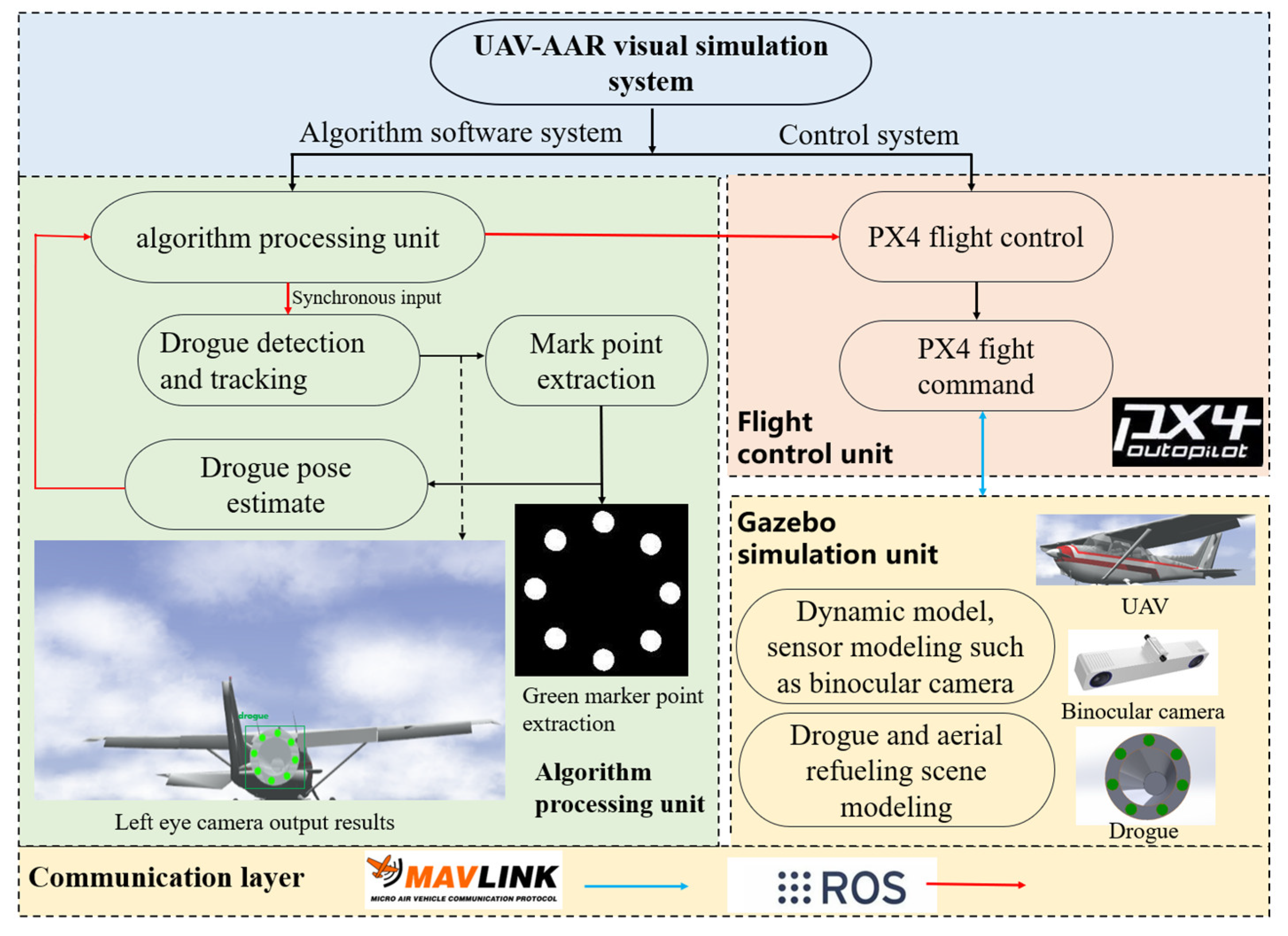
- By constructing the UAV-AAR vision simulation system and the semi-physical UAV-AAR simulation experimental environment, this paper completes the experimental verification of the whole UAV-AAR visual navigation method, such as drogue object detection, object tracking, and the pose estimation algorithm, and the experimental results verify the reliability and robustness of this paper’s method.
2. Related Works
2.1. Drogue Detection and Tracking
2.2. UAV Air Refueling Visual Navigation
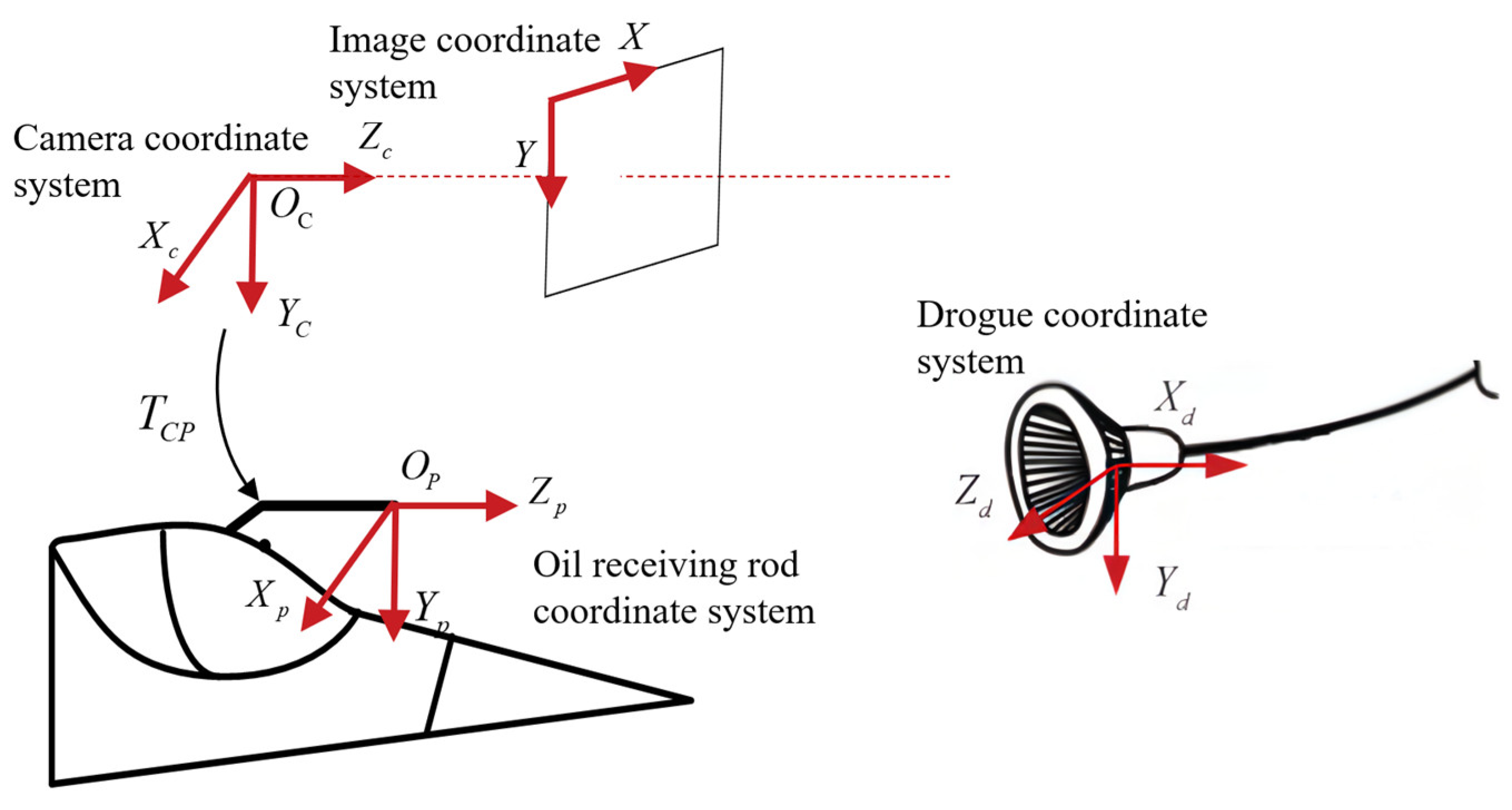
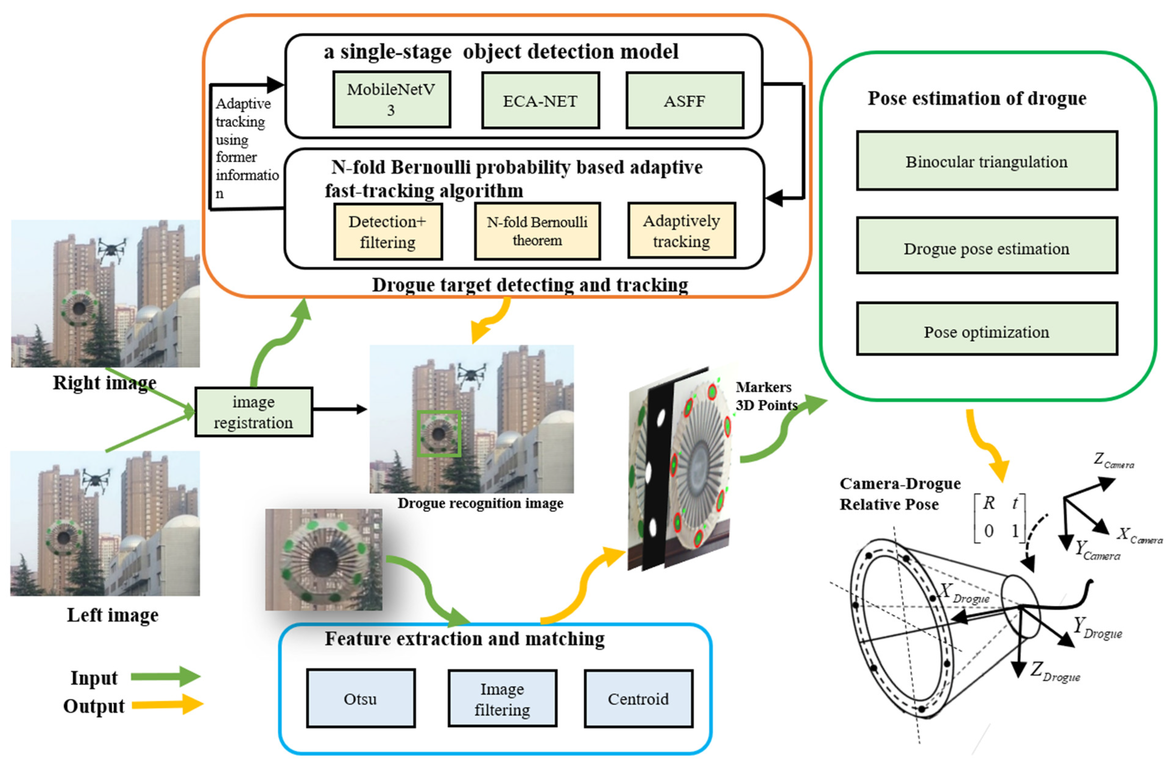
3. Methodology
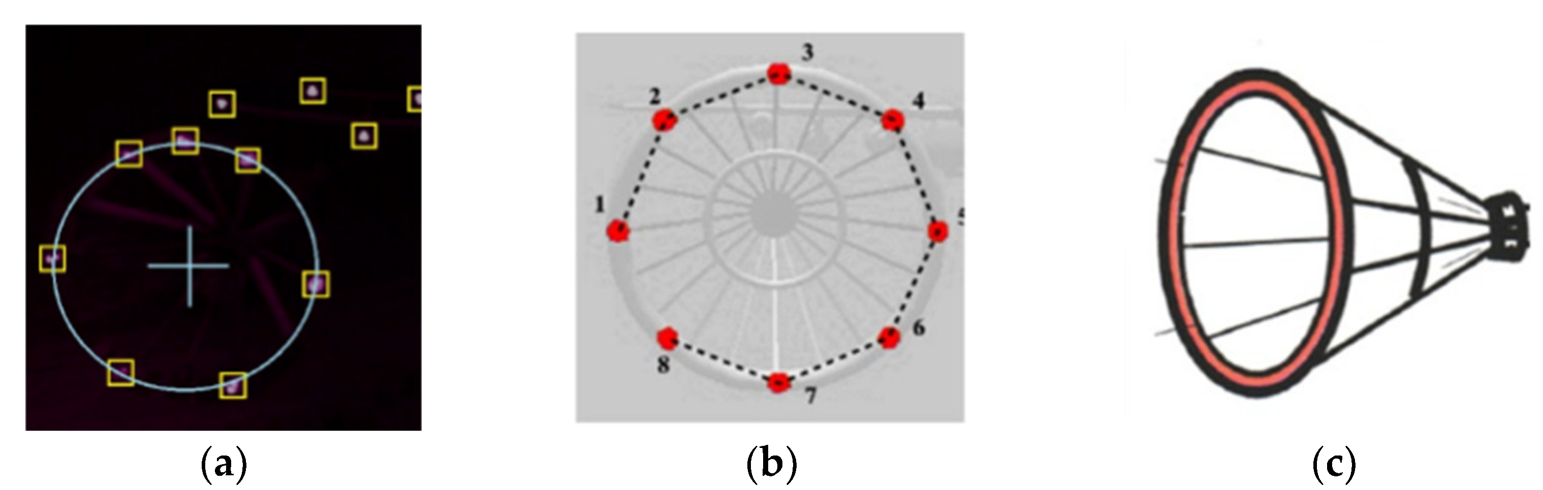
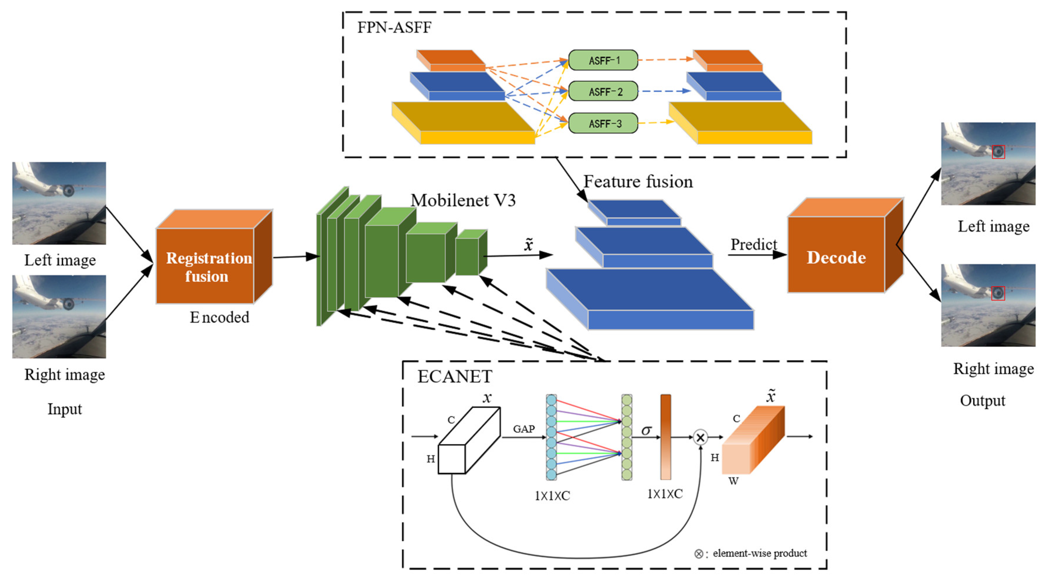
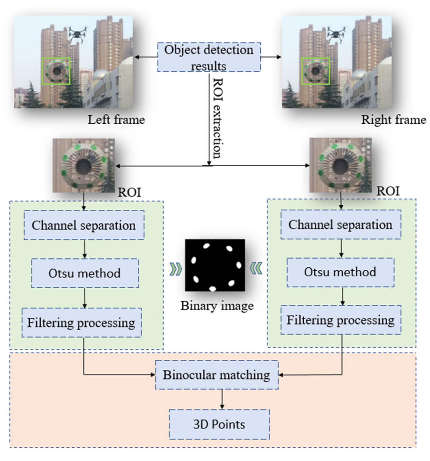
3.1. Drogue Object Detection and Feature Extraction
- (1)
- Accurate identification of drogue targets using an object detection network.
- (2)
- Extraction of the features of optical markers using traditional manual operators and matching to infer the 3D coordinate information of the optical marker.
3.2. Drogue Object-Tracking Algorithm
3.3. Optical-Marker-Assisted Visual Navigation Method
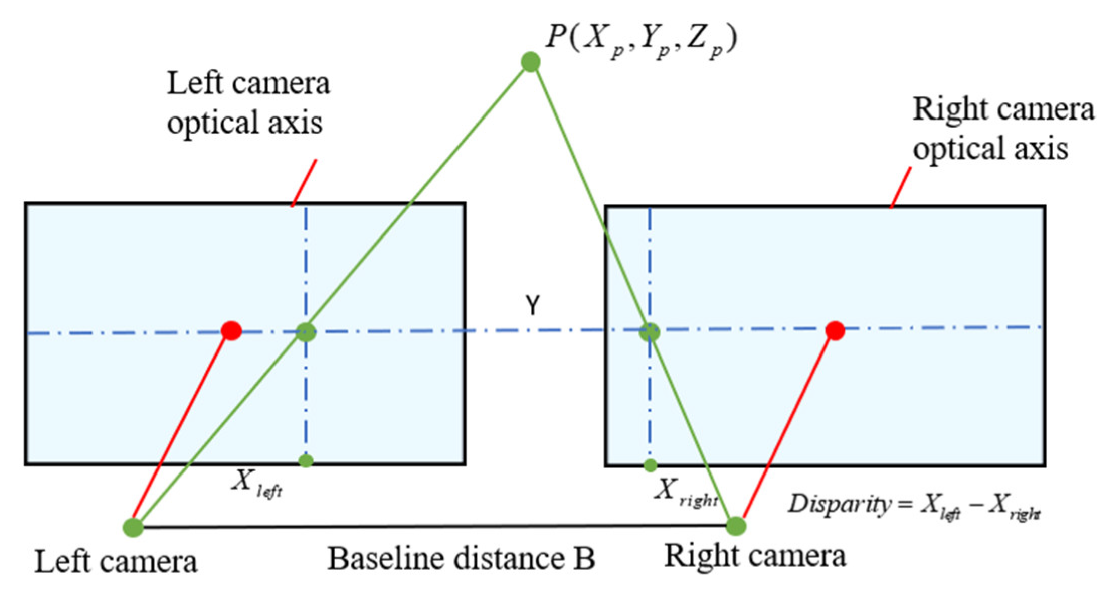
3.3.1. Binocular Triangulation Measurement Method
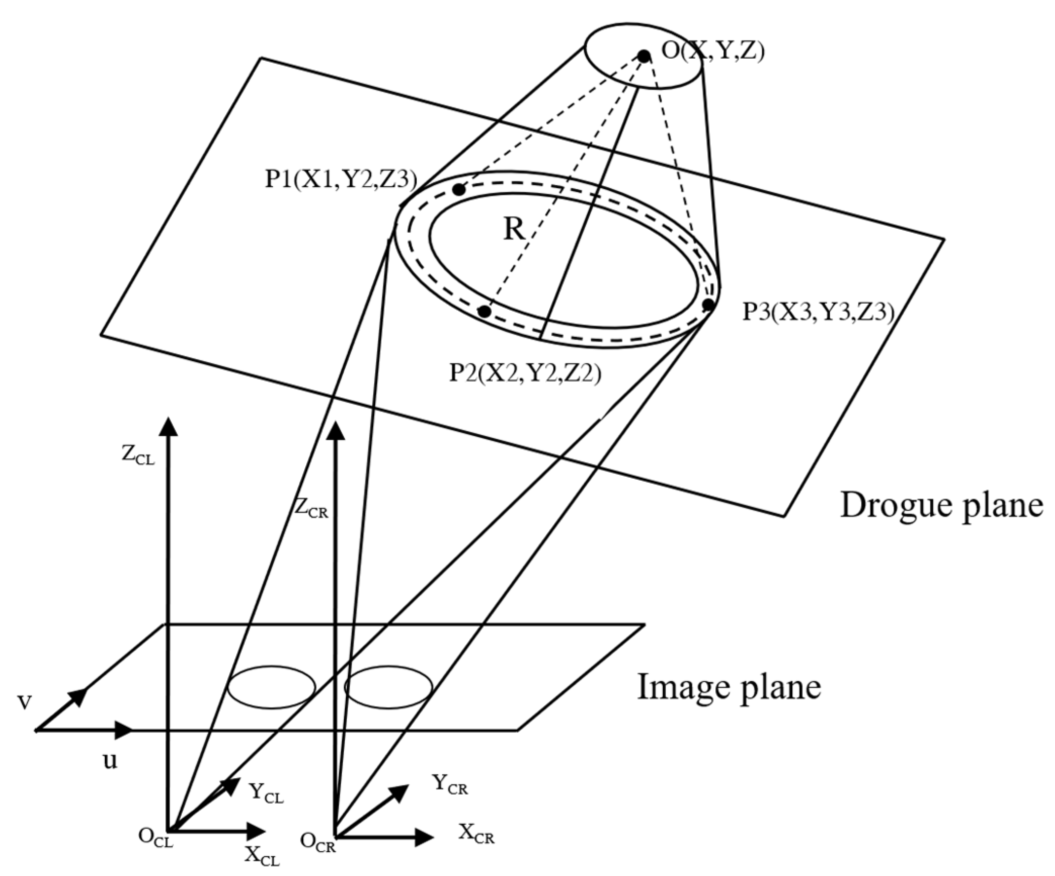
3.3.2. Drogue Pose Estimation Method Based on Binocular Vision
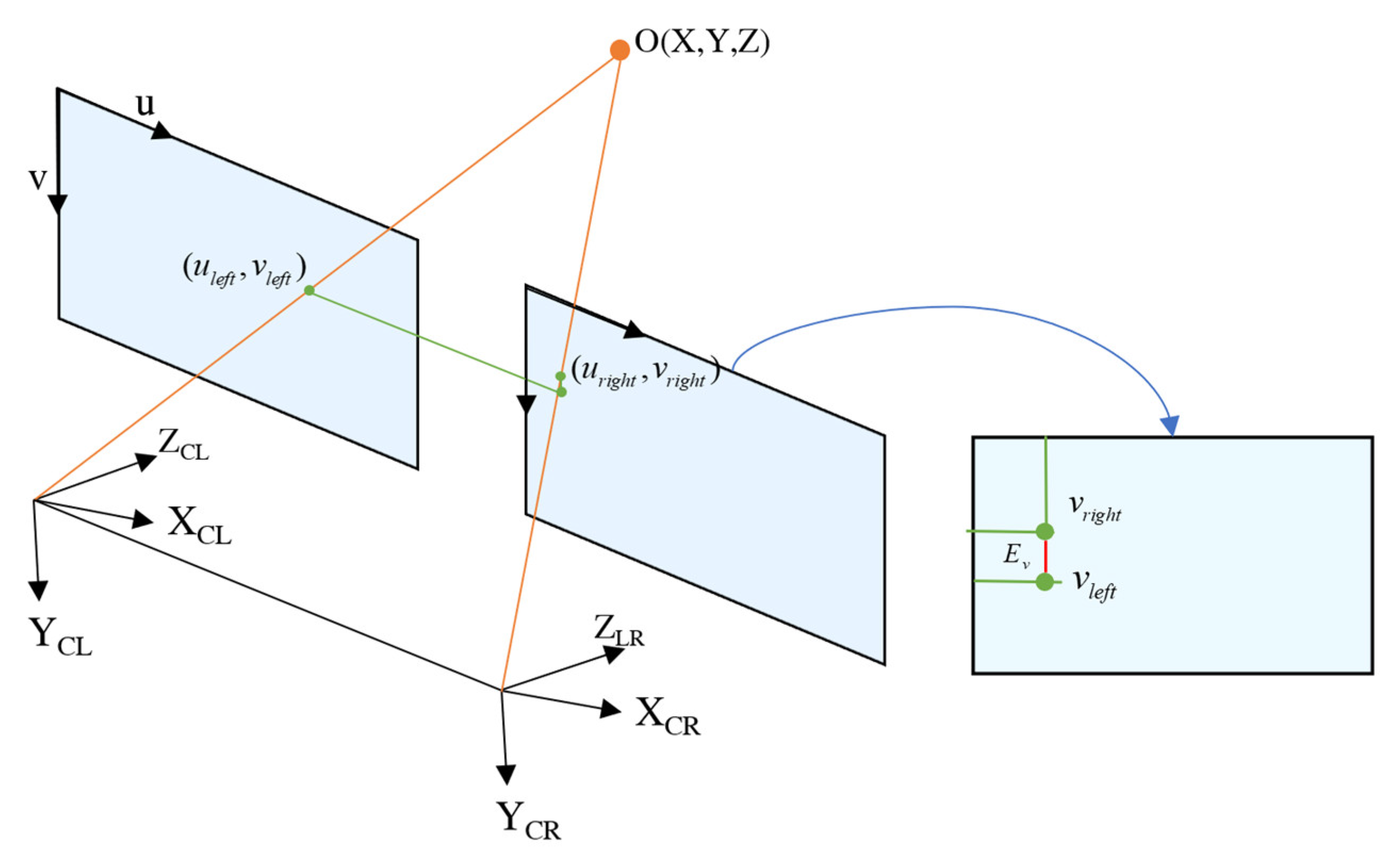
3.3.3. Visual Reprojection-Based Positional Optimization Method
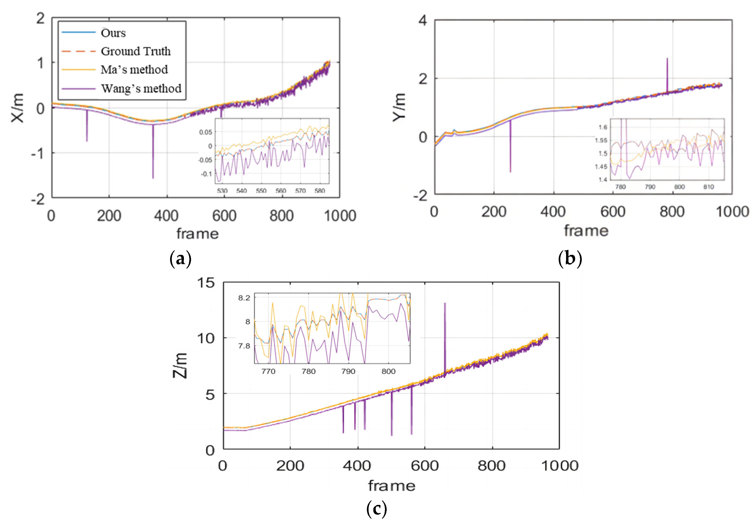
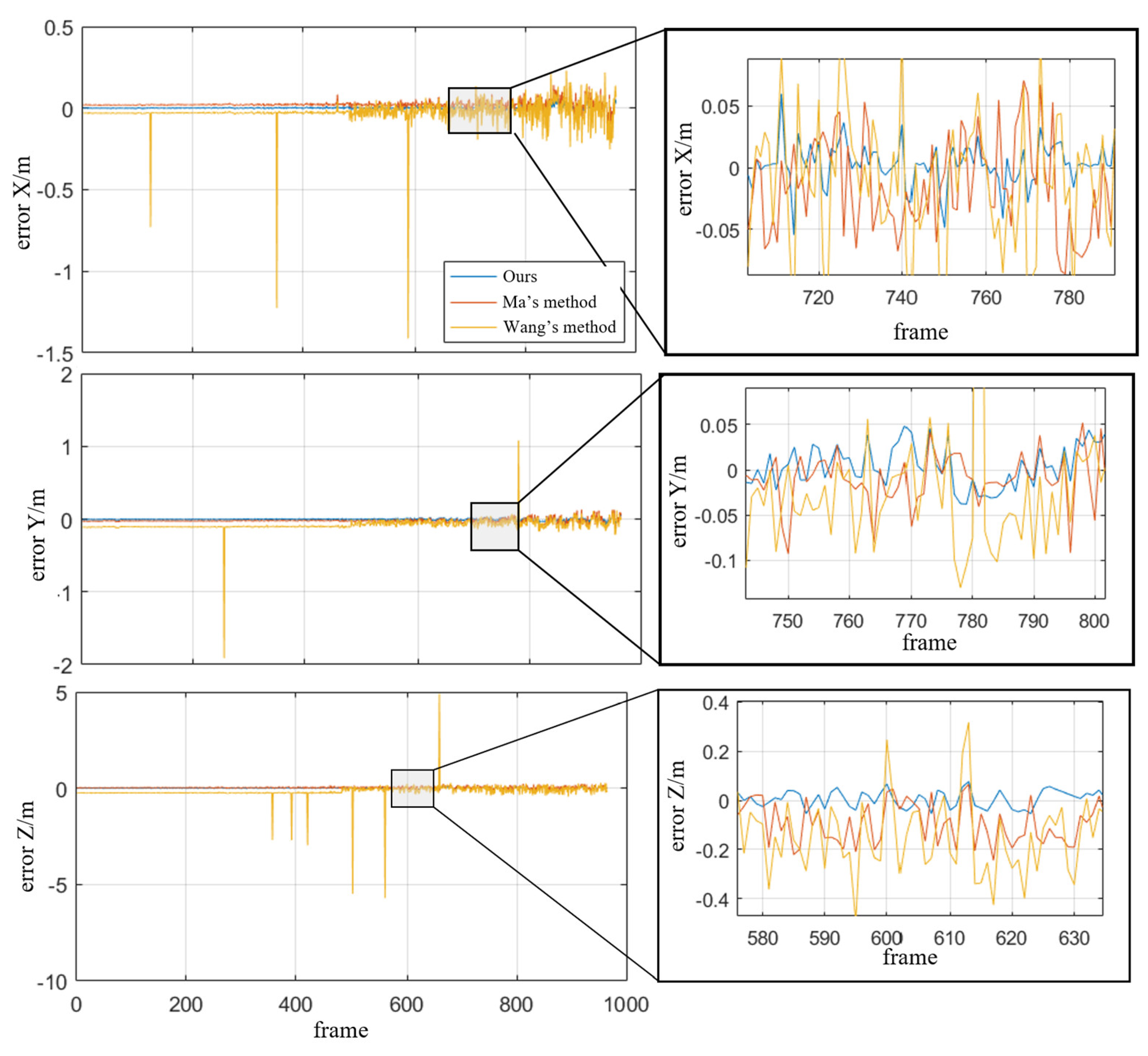
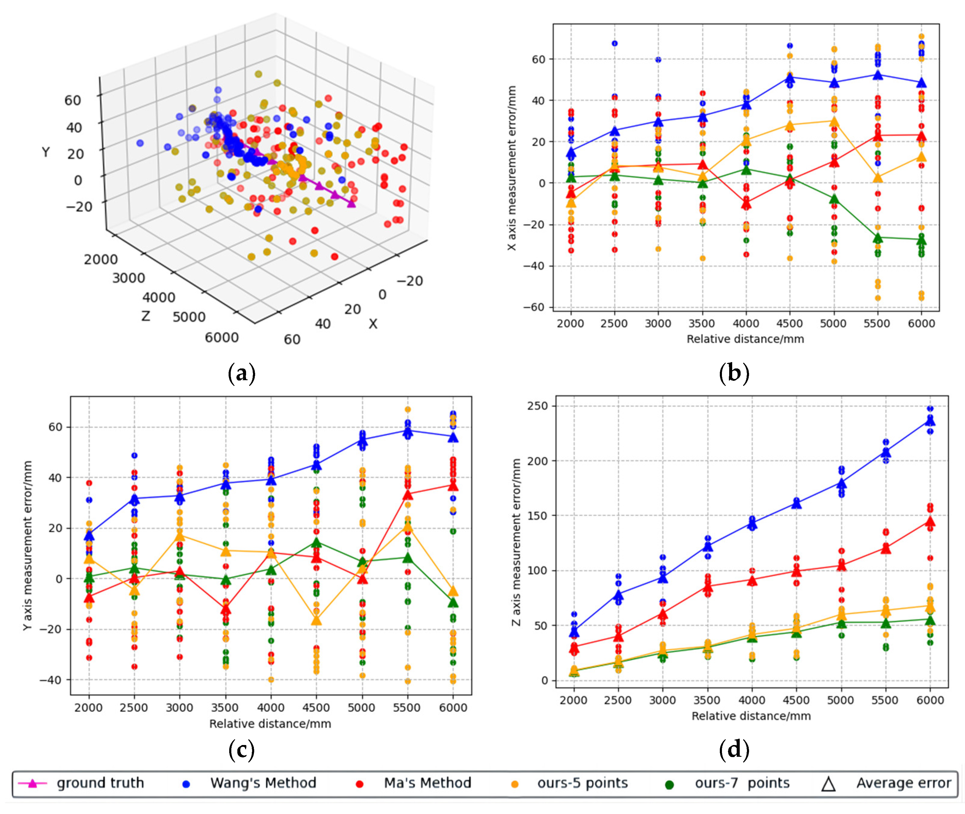
4. Experiment
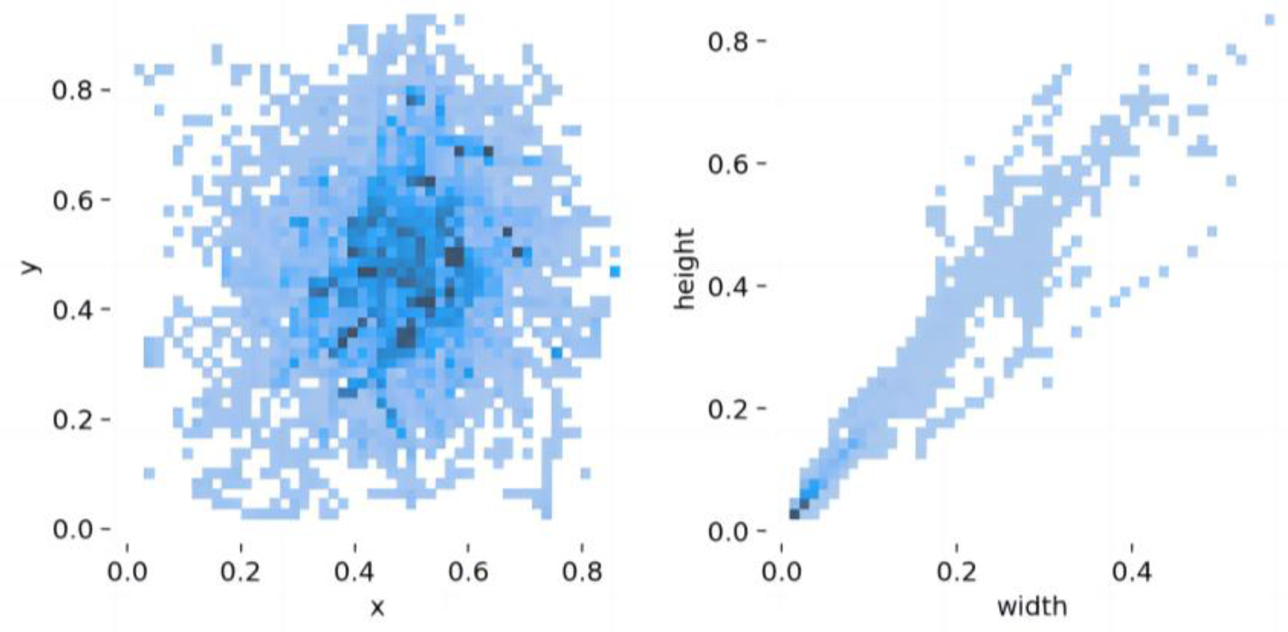
4.1. Dataset
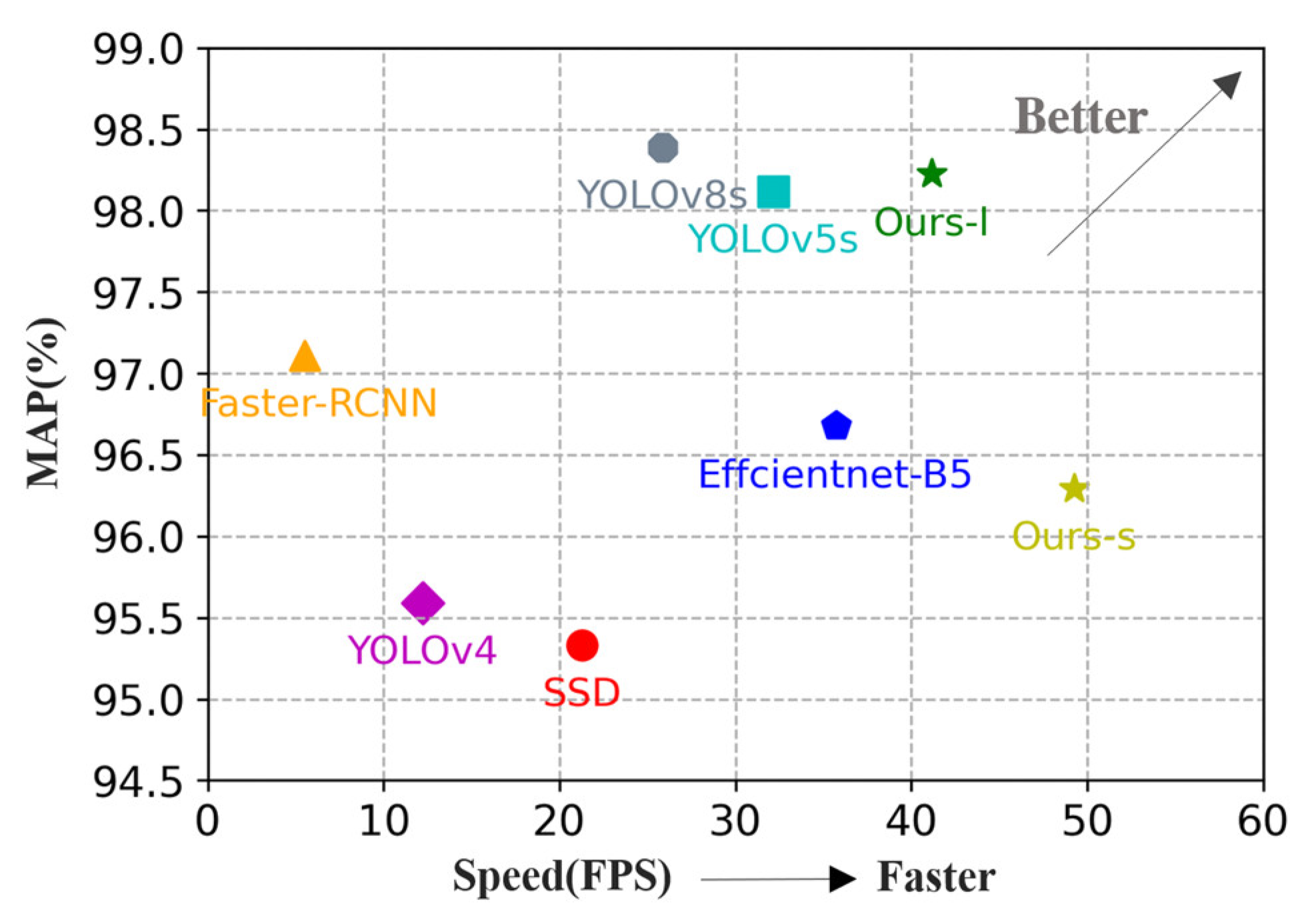
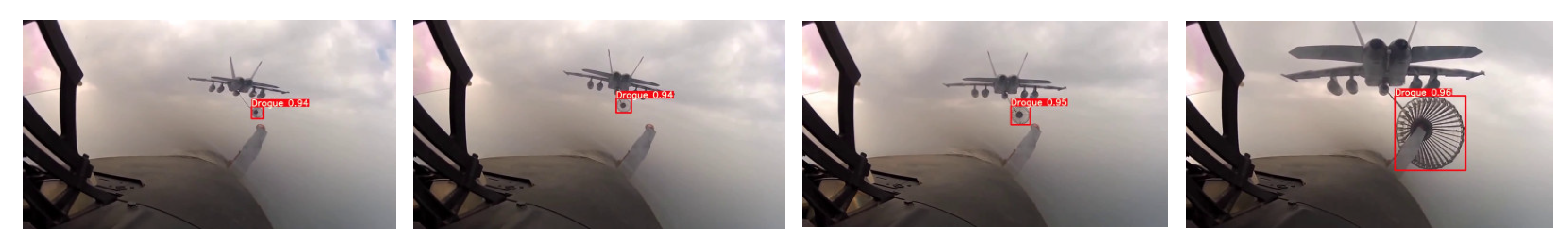
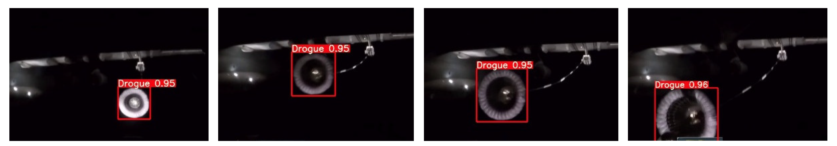
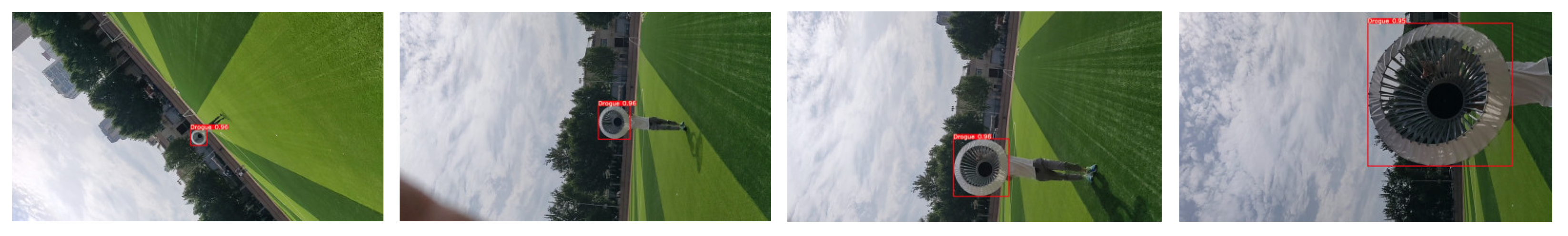
4.2. Drogue Detection Experiment
4.3. UAV Docking Experiment
4.3.1. View Simulation
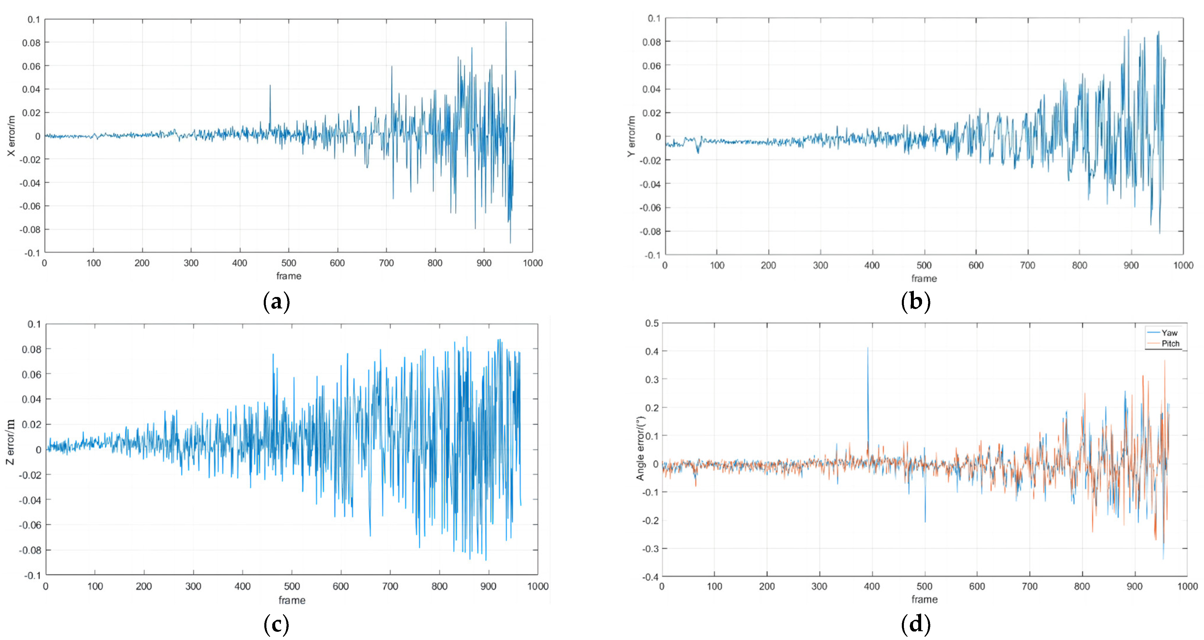
4.3.2. Semi-Physical Simulation Experiments
5. Conclusions and Future Works
Author Contributions
Funding
Data Availability Statement
Acknowledgments
Conflicts of Interest
References
- Mao, W.; Eke, F.O. A Survey of the Dynamics and Control of Aircraft During Aerial Refueling. Nonlinear Dyn. Syst. Theory 2008, 4, 375–388. [Google Scholar]
- Parry, J.; Hubbard, S. Review of Sensor Technology to Support Automated Air-to-Air Refueling of a Probe Configured Uncrewed Aircraft. Sensors 2023, 23, 995. [Google Scholar] [CrossRef] [PubMed]
- Bin, H. Research on Close Range High-Precision Visual Navigation Technology for UAV Aerial Refueling; Nanjing University of Aeronautics and Astronautics: Nanjing, China, 2019. [Google Scholar]
- Wang, H.L.; Ruan, W.Y.; Wang, Y.X.; Wu, J.F.; Zuo, Z.Y. Kang R.L. An accurate measurement method for the position and attitude of the aerial refueling drogue based on the variable angle of view. Tactical Missile Technol. 2020, 135–143. [Google Scholar]
- Ma, Y. Research on Autonomous Aerial Refueling Recognition and Measurement Technology Based on Convolutional Neural Network; University of Chinese Academy of Sciences (Institute of Optoelectronics Technology, Chinese Academy of Sciences): Beijing, China, 2020. [Google Scholar]
- Wang, X.F.; Dong, X.M.; Kong, X.W.; Zhi, J.H. Vision Based Measurement of Refueling Drogue for Autonomous Aerial Refueling. Appl. Mech. Mater. 2014, 590, 618–622. [Google Scholar] [CrossRef]
- Redmon, J.; Divvala, S.; Girshick, R.; Farhadi, A. You Only Look Once: Unified, Real-Time Object Detection/Computer Vision & Pattern Recognition; IEEE: Piscataway, NJ, USA, 2016. [Google Scholar]
- Campos, C.; Elvira, R.; Rodríguez, J.J.G.; Montiel, J.M.M.; Tardós, J.D. Orb-slam3: An accurate open-source library for visual, visual–inertial, and multimap slam. IEEE Trans. Robot. 2021, 37, 1874–1890. [Google Scholar] [CrossRef]
- Qin, T.; Li, P.; Shen, S. Vins-mono: A robust and versatile monocular visual-inertial state estimator. IEEE Trans. Robot. 2018, 34, 1004–1020. [Google Scholar] [CrossRef] [Green Version]
- Huang, G. Visual-Inertial Navigation: A Concise Review. In Proceedings of the 2019 International Conference on Robotics and Automation (ICRA), Montreal, QC, Canada, 20–24 May 2019. [Google Scholar]
- Wang, C.Y.; Bochkovskiy, A.; Liao, H.Y.M. YOLOv7: Trainable bag-of-freebies sets new state-of-the-art for real-time object detectors. arXiv 2022, arXiv:2207.02696. [Google Scholar]
- Bochkovskiy, A.; Wang, C.Y.; Liao, H.Y.M. Yolov4: Optimal speed and accuracy of object detection. arXiv 2020, arXiv:2004.10934. [Google Scholar]
- Tan, M.; Le, Q. Efficientnet: Rethinking model scaling for convolutional neural networks/International conference on machine learning. Proc. Mach. Learn. Res. 2019, 97, 6105–6114. [Google Scholar]
- Zhang, J.; Liu, Z.; Gao, Y.; Zhang, G. Robust Method for Measuring the Position and Orientation of Drogue Based on Stereo Vision. IEEE Trans. Ind. Electron. 2021, 68, 4298–4308. [Google Scholar] [CrossRef]
- Zhang, Z.; Doi, K.; Iwasaki, A.; Xu, G. Unsupervised domain adaptation of high-resolution aerial images via correlation alignment and self training. IEEE Geosci. Remote Sens. Lett. 2020, 18, 746–750. [Google Scholar] [CrossRef]
- Choi, A.J.; Yang, H.H.; Han, J.H. Study on robust aerial docking mechanism with deep learning based drogue detection and docking. Mech. Syst. Signal Process. 2021, 154, 107579. [Google Scholar] [CrossRef]
- Ma, Y.; Zhao, R.; Yan, K.; Liu, E. A real-time embedded drogue detection method based on lightweight convolution neural network for autonomous aerial refueling. Neural Comput. Appl. 2022, 34, 13425–13437. [Google Scholar] [CrossRef]
- Duan, H.; Sun, Y.; Shi, Y. Bionic visual control for probe-and-drogue autonomous aerial refueling. IEEE Trans. Aerosp. Electron. Syst. 2020, 57, 848–865. [Google Scholar] [CrossRef]
- Xu, X.; Duan, H.; Guo, Y.; Deng, Y. A cascade adaboost and CNN algorithm for drogue detection in UAV autonomous aerial refueling. Neurocomputing 2020, 408, 121–134. [Google Scholar] [CrossRef]
- Gao, Y.; Yang, S.; Liu, X. Drogue position measurement of autonomous aerial refueling based on embedded system. Sens. Actuators A Phys. 2023, 353, 114251. [Google Scholar] [CrossRef]
- Martínez, C.; Richardson, T.; Thomas, P.; du Bois, J.L.; Campoy, P. A vision-based strategy for autonomous aerial refueling tasks. Robot. Auton. Syst. 2013, 61, 876–895. [Google Scholar] [CrossRef]
- Zhong, Z.; Li, D.; Wang, H.; Su, Z. Drogue Position and Tracking with Machine Vision for Autonomous Air Refueling Based on EKF. In Proceedings of the 2017 9th International Conference on Intelligent Human-Machine Systems and Cybernetics (IHMSC), Hangzhou, China, 26–27 August 2017. [Google Scholar]
- Campa, G.; Napolitano, M.R.; Fravolini, M.L. Simulation Environment for Machine Vision Based Aerial Refueling for UAVs. IEEE Trans. Aerosp. Electron. Syst. 2009, 45, 138–151. [Google Scholar] [CrossRef]
- Fravolini, M.L.; Ficola, A.; Campa, G.; Napolitano, M.R.; Seanor, B. Modeling and control issues for autonomous aerial refueling for UAVs using a probe–drogue refueling system. Aerosp. Sci. Technol. 2004, 8, 611–618. [Google Scholar] [CrossRef]
- Ma, Y.; Zhao, R.; Liu, E.; Zhang, Z.; Yan, K. A Novel Method for Measuring Drogue-UAV Relative Pose in Autonomous Aerial Refueling Based on Monocular Vision. IEEE Access 2019, 7, 139653–139667. [Google Scholar] [CrossRef]
- Zhao, K.; Sun, Y.; Zhang, Y.; Li, H. Monocular visual position and attitude estimation method of a drogue based on coaxial constraints. Sensors 2021, 21, 5673. [Google Scholar] [CrossRef] [PubMed]
- Wilson, D.B.; Göktoğan, A.H.; Sukkarieh, S. Experimental Validation of a Drogue Estimation Algorithm for Autonomous Aerial Refueling. In Proceedings of the 2015 IEEE International Conference on Robotics and Automation, ICRA 2015, Seattle, WA, USA, 26–30 May 2015; pp. 5318–5323. [Google Scholar]
- Qing, Z.; Xu, Y.; Buick, G. Visual navigation technology for UAV hose type autonomous aerial refueling. Navig. Position. Timing 2020, 7, 40–47. [Google Scholar]
- Wang, X.; Dong, X.; Kong, X. Machine Vision Assisted Plug and Cone UAV Autonomous Aerial Refueling Simulation. Sci. Technol. Eng. 2013, 13, 5245–5250. [Google Scholar]
- Luo, D.; Shao, J.; Xu, Y.; Zhang, J. Docking navigation method for UAV autonomous aerial refueling. Sci. China Inf. Sci. 2019, 62, 10203. [Google Scholar] [CrossRef] [Green Version]
- Yong, Q.; Wang, H.; Su, Z.; Peng, Y. Vision based autonomous aerial refueling drogue detection and tracking. Tactical Missile Technol. 2016, 87–93. [Google Scholar]
- Xie, H.; Wang, H. Close range navigation method for automatic aerial refueling based on binocular vision. J. Beijing Univ. Aeronaut. Astronaut. 2011, 37, 206–209. [Google Scholar]
- Pollini, L.; Innocenti, M.; Mati, R. Vision Algorithms for Formation Flight and Aerial Refueling with Optimal Marker Labeling. In Proceedings of the AIAA Modeling & Simulation Technologies Conference & Exhibit, San Francisco, CA, USA, 15–18 August 2005. [Google Scholar]
- Sun, Y.; Xia, X.; Xin, L.; He, W. RPnP Pose Estimation Optimized by Comprehensive Learning Pigeon-Inspired Optimization for Autonomous Aerial Refueling. In Advances in Guidance, Navigation and Control: Proceedings of 2022 International Conference on Guidance, Navigation and Control; Springer Nature: Singapore, 2023. [Google Scholar]
- Howard, A.; Sandler, M.; Chu, G.; Chen, L.C.; Chen, B.; Tan, M.; Wang, W.; Zhu, Y.; Pang, R.; Vasudevan, V.; et al. Searching for mobilenetv3. In Proceedings of the IEEE/CVF International Conference on Computer Vision, Seoul, Republic of Korea, 27 October–2 November 2019; pp. 1314–1324. [Google Scholar]
- Wang, Q.; Wu, B.; Zhu, P.; Li, P.; Zuo, W.; Hu, Q. ECA-Net: Efficient Channel Attention for Deep Convolutional Neural Networks. In Proceedings of the Conference on Computer Vision and Pattern Recognition (CVPR), Seattle, WA, USA, 16–20 June 2019; pp. 11531–11539. [Google Scholar]
- Hu, J.; Shen, L.; Sun, G. Squeeze-and-Excitation Networks. In Proceedings of the IEEE Conference on Computer Vision and Pattern Recognition, Salt Lake City, UT, USA, 18–23 June 2018; pp. 7132–7141. [Google Scholar]
- Liu, S.; Huang, D.; Wang, Y. Learning spatial fusion for single-shot object detection. arXiv 2019, arXiv:1911.09516. [Google Scholar]
- Rasol, J.; Xu, Y.; Zhou, Q.; Hui, T.; Zhang, Z. N-fold Bernoulli probability based adaptive fast-tracking algorithm and its application to autonomous aerial refueling. Chin. J. Aeronaut. 2022, 36, 356–368. [Google Scholar] [CrossRef]
- Barnard, S.T.; Fischler, M.A. Computational stereo. ACM Comput. Surv. 1982, 14, 553–572. [Google Scholar] [CrossRef]
- Huber, P.J. Robust estimation of a location parameter. Breakthr. Stat. Methodol. Distrib. 1964, 35, 73–101. [Google Scholar] [CrossRef]
- Wang, Y. Gauss-Newton method. Comput. Stat. 2012, 4, 415–420. [Google Scholar] [CrossRef]
- Jocher, G. yolov5. 2021. Available online: https://github.com/ultralytics/yolov5 (accessed on 31 January 2022).
- Ren, S.; He, K.; Girshick, R.; Sun, J. Faster r-cnn: Towards real-time object detection with region proposal networks. Adv. Neural Inf. Process. Syst. 2015, 28, 1137–1149. [Google Scholar] [CrossRef] [PubMed] [Green Version]
- Liu, W.; Anguelov, D.; Erhan, D.; Szegedy, C.; Reed, S.; Fu, C.Y.; Berg, A.C. Ssd: Single Shot Multibox Detector. In European Conference on Computer Vision; Springer: Cham, Switzerland, 2016; pp. 21–37. [Google Scholar]
- Jocher, G.; Chaurasia, A.; Oiu, J. YOLO by Ultralytics. Available online: https://github.com/ultralytics/ultralytics (accessed on 31 January 2022).


| Target Detection Model | Precision | Recall | mAP0.5 | GFLOPs | Spend (s/img) |
|---|---|---|---|---|---|
| YOLOv8s [46] | 92.66% | 95.21% | 98.39% | 28.6 | 0.0387 |
| YOLOv5s [45] | 91.74% | 95.99% | 98.12% | 16.5 | 0.0311 |
| Effcientnet-B5 [13] | 91.07% | 93.48% | 96.68% | 9.9 | 0.0280 |
| Faster-RCNN [44] | 94.8% | 96.34% | 97.11% | 344.4 | 0.181 |
| SSD [45] | 91.79% | 92.03% | 95.33% | 31.0 | 0.0470 |
| YOLOv4 [46] | 92.05% | 92.05% | 95.59% | 52.0 | 0.0818 |
| ours-l | 93% | 99.5% | 98.23% | 9.3 | 0.0243 |
| ours-s | 94.29 | 91.49% | 96.29% | 6.0 | 0.0202 |
| Method | Location Error | ||
|---|---|---|---|
| X Axis Error/mm | Y Axis Error/mm | Z Axis Error/Z | |
| Wang’s method | ≤70 | ≤65 | ≤3.95% |
| Ma’s method | ≤50 | ≤50 | ≤2.39% |
| Ours-5 Points | ≤65 | ≤65 | ≤1.21% |
| Ours-7 Points | ≤40 | ≤40 | ≤1.03% |
Disclaimer/Publisher’s Note: The statements, opinions and data contained in all publications are solely those of the individual author(s) and contributor(s) and not of MDPI and/or the editor(s). MDPI and/or the editor(s) disclaim responsibility for any injury to people or property resulting from any ideas, methods, instructions or products referred to in the content. |
© 2023 by the authors. Licensee MDPI, Basel, Switzerland. This article is an open access article distributed under the terms and conditions of the Creative Commons Attribution (CC BY) license (https://creativecommons.org/licenses/by/4.0/).
Share and Cite
Gong, K.; Liu, B.; Xu, X.; Xu, Y.; He, Y.; Zhang, Z.; Rasol, J. Research of an Unmanned Aerial Vehicle Autonomous Aerial Refueling Docking Method Based on Binocular Vision. Drones 2023, 7, 433. https://doi.org/10.3390/drones7070433
Gong K, Liu B, Xu X, Xu Y, He Y, Zhang Z, Rasol J. Research of an Unmanned Aerial Vehicle Autonomous Aerial Refueling Docking Method Based on Binocular Vision. Drones. 2023; 7(7):433. https://doi.org/10.3390/drones7070433
Chicago/Turabian StyleGong, Kun, Bo Liu, Xin Xu, Yuelei Xu, Yakun He, Zhaoxiang Zhang, and Jarhinbek Rasol. 2023. "Research of an Unmanned Aerial Vehicle Autonomous Aerial Refueling Docking Method Based on Binocular Vision" Drones 7, no. 7: 433. https://doi.org/10.3390/drones7070433