Article

Joint Beamforming and Phase Shift Design for Hybrid IRS and UAV-Aided Directional Modulation Networks

1
School of Information and Communication Engineering, Hainan University, Haikou 570228, China
2
School of Electronic and Optical Engineering, Nanjing University of Science and Technology, Nanjing 210094, China
3
Digital Fujian Institute of Big Data for Agriculture, Fujian Agriculture and Forestry University, Fuzhou 350002, China
4
School of Science and Security Research Institute, Edith Cowan University, Perth, WA 6027, Australia
5
School of Engineering, University of Kent, Canterbury CT2 7NT, UK
*
Author to whom correspondence should be addressed.
Drones 2023, 7(6), 364; https://doi.org/10.3390/drones7060364
Submission received: 27 April 2023 / Revised: 26 May 2023 / Accepted: 29 May 2023 / Published: 30 May 2023
(This article belongs to the Special Issue UAVs Communications for 6G)

Abstract

:
Recently, intelligent reflecting surfaces (IRSs) and unmanned aerial vehicles (UAVs) have been integrated into wireless communication systems to enhance the performance of air–ground transmission. To balance performance, cost, and power consumption well, a hybrid IRS and UAV-assisted directional modulation (DM) network is investigated in this paper in which the hybrid IRS consisted of passive and active reflecting elements. We aimed to maximize the achievable rate by jointly designing the beamforming and phase shift matrix (PSM) of the hybrid IRS subject to the power and unit-modulus constraints of passive IRS phase shifts. To solve the non-convex optimization problem, a high-performance scheme based on successive convex approximation and fractional programming (FP) called the maximal signal-to-noise ratio (SNR)-FP (Max-SNR-FP) is proposed. Given its high complexity, we propose a low-complexity maximal SNR-equal amplitude reflecting (EAR) (Max-SNR-EAR) scheme based on the maximal signal-to-leakage-noise ratio method, and the criteria of phase alignment and EAR. Given that the active and passive IRS phase shift matrices of both schemes are optimized separately, to investigate the effect of jointly optimizing them to improve the achievable rate, a maximal SNR majorization-minimization (MM) (Max-SNR-MM) scheme using the MM criterion to design the IRS PSM is proposed. Simulation results show that the rates harvested by the three proposed methods were slightly lower than those of the active IRS with higher power consumption, which were 35% higher than those of no IRS and random phase IRS, while passive IRS achieved only about a 17% rate gain over the latter. Moreover, compared with the Max-SNR-FP, the proposed Max-SNR-EAR and Max-SNR-MM methods caused obvious complexity degradation at the price of slight performance loss.

1. Introduction

Wireless networks serve in a wide variety of civilian and military applications, and have become an essential part of our routine [1,2]. Improving the performance of wireless communication is a popular research topic. Unmanned aerial vehicles (UAVs), thanks to their low cost, high flexibility, and high probability of line-of-propagation (LoP) links, have become an attractive means of improving air–ground transmission quality [3]. In general, UAVs can not only act as base stations [4] and relays [5] to transmit or forward signals, but can also be used for data collection [6] and positioning [7]. UAV transmission technology has been widely explored. For instance, the authors in [8] considered the deployment of a cellular network in which UAV-to-UAV launch–receive pairs used the sane spectrum as that of the cellular ground users’ uplink, and the performance of underlay and overlay spectrum sharing mechanisms was analyzed and compared. In [9], to enhance the throughput of a single-cell multi-user orthogonal frequency division multiple access network with single UAV while guaranteeing user fairness, an efficient method was proposed that outperformed the random and cellular schemes in terms of user fairness and sum rate. A UAV-enabled relay under malicious jamming was considered in [10], and the successive convex approximation (SCA) algorithm was employed to maximize the end-to-end throughput. However, UAV networks also present some challenges that impact their performance. For instance, LoP links might be blocked, and UAV forwarding signals increase the power consumption and affect the endurance of UAVs.
As an effective solution to the above-mentioned problems, intelligent reflecting surfaces (IRSs) have been explored as an intelligent and reconfigurable paradigm for future wireless communications [11]. An IRS is a plane that consists of many reflective elements that could intelligently tune the phase and amplitude of the incident signal to reconfigure the wireless transmission environment, and is an energy and cost-efficient tool for enhancing the performance of a wireless network. Driven by these advantages, IRS-aided UAV networks have been widely investigated. To minimize the weighted sum bit error rate of all IRSs, the authors in [12] considered a symbiotic UAV-aided IRS radio network, and a relaxation-based scheme was proposed. In [13], two approaches were proposed to maximize the spectrum and energy effectiveness of an IRS-aided UAV network by jointly deriving a UAV trajectory, and active and passive beamforming, and the proposed methods yielded better performance compared to that of the baselines. Security has also been researched. A secure IRS-assisted UAV system was investigated in [14], and an SCA scheme was proposed to maximize the secrecy rate (SR). With the aim of maximizing the average SR of a secure IRS-aided UAV system in [15], the fractional programming and SCA methods were applied to deal with the non-convex optimization problem. Different from the above works that focused on a single user, a multi-user network that employed UAV and IRS to support terahertz communication was considered in [16], and an iteration strategy was proposed to maximize the minimal average achievable rate among all users.
Directional modulation (DM), which significantly boosts the rate of wireless communication systems, has evolved into a useful strategy for fifth-generation millimeter-wave communication systems [17,18,19]. DM is capable of guiding standard baseband symbols to the intended direction while warping the signal constellation diagram outside that direction [20]. In [21], a signal was generated in a predetermined direction through tuning the phase of each antenna element at the forefront of the radio frequency. The authors in [22] sketched a process for determining how to convert antenna elements into sending signals only in a given direction, and the DM array could transmit signals over a narrower beam width compared to that of a traditional reconfigurable array. For the above works, DM synthesis was desgined at the radio frequency frontend, which lacks flexibility. To address this problem, the researchers transferred the design of DM synthesis from the radio frequency frontend to the baseband. In [23], on the basis of maximizing the signal-to-artificial noise (AN) ratio and signal-to-leakage-noise ratio approaches designed at the baseband, an AN projection matrix and precoder vector were obtained to maximize the SR of a multi-beam DM network. An AN-aided zero-forcing synthesis scheme that achieved the dynamic characteristics of multi-beam DM through the random varying of AN vector was proposed in [24], which was easier and more effective to implement than traditional dynamic multi-beam DM synthesis methods are in wireless networks with a certain level of performance loss. In [25], the authors investigated a DM system with malicious jamming and proposed three receive beamforming algorithms to boost the SR.
In particular, conventional DM networks can only transmit single-bit streams, while the emergence of IRS enabled DM networks to send multiple bit streams. An energy and cost-efficient IRS can be employed to create multiple user-friendly and controllable paths to transmit two-bit streams or increase the rate to enhance the performance of DM systems. For example, in [26], to transmit two-bit streams from Alice to Bob and maximize the SR of an IRS-assisted DM network, the precoder vectors and phase shift matrix (PSM) of the IRS were jointly devised with high-performance general alternating iterative and low-complexity null-space projection algorithms. However, the design of receiver beamforming was not investigated in [26]. To investigate the effect of receiver beamforming on performance improvement on the basis of the system model of [26], the authors in [27] proposed two optimization algorithms to maximize the receiver power sum by jointly optimizing the PSM at IRS and receiver beamforming vectors at the user. In [28], aiming to maximize the SR of an IRS-assisted multiple-input single-output (MISO) DM network, the semi-definite relaxation method was utilized to derive the precoding and IRS PSM when the location information of an eavesdropper is available. Thanks to a combination with IRS, SR performance was significantly boosted.
However, all the above work was conducted on the basis of a fully passive IRS, and a satisfactory achievable rate of the system may not be ensured due to the effect of “double fading” in cascaded channels. To effectively combat this effect and enhance the performance of passive IRS-aided wireless communication networks, a fully active IRS was recently investigated [29,30,31,32,33], and the simulation results showed that active IRS achieved significant performance improvements compared to a passive IRS. However, the higher rate achieved by active IRS comes at the price of high hardware cost and power consumption [34]. To overcome the limitations of fully passive and fully active IRSs, a hybrid active-passive IRS was proposed [35]. The main idea of the hybrid IRS is employing some active elements to substitute those of the passive IRS. Active elements with the signal amplification of a hybrid IRS can effectively compensate for the cascade path loss (PL), and increase the achievable rate [36]. In [37], to explore the potential of hybrid relay–IRS in helping single-user mobile edge computing systems in computational offloading, an efficient scheme was proposed to design received beamforming, IRS reflection coefficients, and computational parameters, and the latency was dramatically reduced with the help of the IRS. In [38], a hybrid IRS-assisted covert transmission network was proposed to boost the performance of traditional covert communication networks, and an alternate algorithm with closed-form expression was derived to obtain the transmission power and IRS PSM. Unlike previous works that only considered single or multiple users and a single objective, a hybrid IRS-aided integrated sensing and communication network with multiple users and objectives was investigated in [39], aimed at maximizing the worst-case target illumination power; an approach was proposed to design precoding and IRS coefficients.
In fact, an IRS needs to be installed on the surface of the object. However, when there is no installation plane and/or emergency communication is needed, such as disaster relief, mounting an IRS on an UAV is an effective way to solve this challenge. In this way, not only can signal enhancement be achieved, but the position of the IRS can also be flexibly adjusted, and signal coverage may be extended. Given the benefits of UAV and hybrid IRS in terms of enhancing the performance of a wireless network, it is a reasonable choice to combine them with a conventional DM network to balance the performance and power consumption. So far, to the best of the authors’ knowledge, hybrid IRS and UAV-aided DM systems have not been investigated yet. In this paper, we employ a hybrid IRS to further enhance the performance of passive IRS-aided DM networks. The main contributions of this work are summarized as follows:
1.
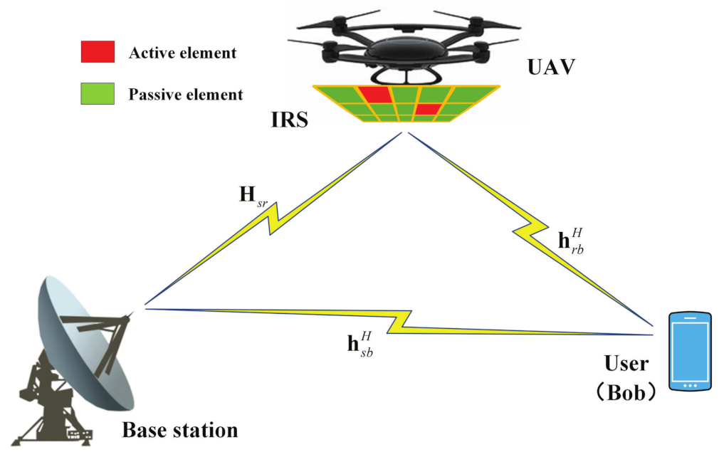
To balance performance, cost, and power consumption well, a hybrid IRS and UAV-aided DM system model is proposed. Aiming at maximizing the achievable rate, an optimization problem of maximizing the signal-to-noise ratio (SNR) is established, and the maximal SNR-fractional programming (FP) (Max-SNR-FP) method is proposed to jointly optimize the transmit beamforming vector and hybrid IRS PSM by solving one and giving another. In this scheme, the beamforming vector and passive IRS PSM are derived via the SCA algorithm, and the active IRS PSM is computed with the FP method.
2.
Given the high computational complexity of the Max-SNR-FP scheme, a low-complexity alternating iteration method named maximum SNR-equal amplitude reflecting (EAR) (Max-SNR-EAR) is subsequently proposed. In this method, by utilizing the maximal signal-to-leakage-noise ratio (SLNR) criterion, the beamforming vector is obtained. Then, the phases of passive and active IRS phase shift matrices are computed on the basis of the criteria of phase alignment, while the amplitude of the active IRS PSM is obtained via the EAR criterion.
3.
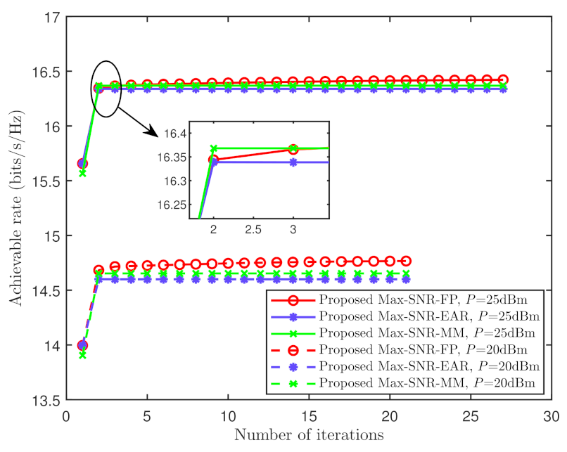
Given that the passive and active IRS phase shift matrices of the proposed Max-SNR-FP and Max-SNR-EAR methods were designed separately, to investigate the effect of jointly optimizing them on performance improvement, low-complexity alternating optimization algorithm Max-SNR-MM is proposed to maximize the achievable rate. The majorization–minimization (MM) criterion was employed to optimize the hybrid IRS phase-shift matrix. The simulation results clearly show that the achievable rates harvested with the three proposed methods were higher than those without IRS, random-phase IRS, and passive IRS. In addition, when the number of hybrid IRS phase shift elements tended towards a large scale, the difference in achievable rates among these three proposed methods was trivial.
The remainder of this paper is organized as follows. In Section 2, we describe the system model of the hybrid IRS and UAV-aided DM network. Section 3 presents the Max-SNR-FP scheme. The Max-SNR-EAR scheme is described in Section 4. The Max-SNR-MM scheme is outlined in Section 5. We present the numerical simulation results in Section 6. In Section 7, the conclusions are drawn.
Notations: in this article, vectors and matrices are shown in boldface lowercase and uppercase letters, respectively. ( · ) * , ( · ) T , ( · ) H , Tr ( · ) , { · } , λ max { · } , diag { · } , and blkdiag { · } stand for the conjugate, transpose, conjugate transpose, trace, real part, maximal eigenvalue of the matrix, diagonal, and block diagonal matrix operations, respectively. | · | refers to the scalar’s absolute value or the matrix’s determinant. I N and C N × N stand for the identity matrix and complex-valued matrix space of N × N , respectively.

2. System Model

As indicated in Figure 1, a hybrid IRS and UAV-aided DM network was considered in which the IRS was installed on a UAV, assuming that the UAV operated at a sufficient altitude, and all channels were line-of-propagation. There were a base station (BS) with N antennas and a user Bob with single antenna. The hybrid IRS was equipped with M elements that consisted of M a active and M p passive IRS reflecting elements ( 1 M a M p , M = M a + M p ). It was assumed that the active elements enabled adjustments in both the amplitude and phase, while the passive ones only tuned the phase of the incident signal. The signals that reflected more than or equal to twice on the hybrid IRS were negligible due to the severe PL [40]. We supposed that all the channel state information was completely accessible owing to the channel estimation [41].
Similar to a conventional fully passive IRS, it was assumed that each element of the hybrid IRS could independently reflect the incident signals. Let us denote the set of M a active elements by Ω . Θ = diag { θ 1 , , θ m , , θ M } C M × M , Ψ = diag { ψ 1 , , ψ m , , ψ M } C M × M , and Φ = diag { ϕ 1 , , ϕ m , , ϕ M } C M × M represent the reflection coefficients of total elements, active elements, and passive elements of hybrid IRS, respectively, where
θ m = | β m | e j μ m , if m Ω , e j μ m , otherwise ,
μ m [ 0 , 2 π ) is the phase, and | β m | represents the amplifying coefficient that is subject to the power of the IRS active elements. Let us define
θ = [ θ 1 , , θ m , , θ M ] H , ψ = [ ψ 1 , , ψ m , , ψ M ] H , ϕ = [ ψ 1 , , ϕ m , , ϕ M ] H ,
Ψ = E M a Θ , Φ = E M p Θ ,
where
E M a + E M p = I M , E M a E M p = 0 M ,
Non-zero elements of diagonal matrix E M a C M × M were a unity whose positions were determined via Ω .
The transmission signal at BS is expressed as follows:
s = P v x ,
where P represents the transmit power, v C N × 1 and x are the beamforming vector and the information symbol satisfying v H v = 1 and E [ x 2 ] = 1 , respectively.
In the presence of the PL, the received signal at Bob is given by
y b = ( ρ s r b h r b H Θ H s r + ρ s b h s b H ) s + ρ r b h r b H Ψ n r + n b = P ( ρ s r b h r b H Ψ H s r + ρ s r b h r b H Φ H s r + ρ s b h s b H ) v x + ρ r b h r b H Ψ n r + n b ,
where ρ s r b = ρ s r ρ r b represents the synthetic PL coefficient of BS-to-IRS channel and IRS-to-Bob channel, ρ s b and ρ r b stand for the PL coefficient of BS-to-Bob channel and IRS-to-Bob channel, respectively. n r C N ( 0 , σ r 2 I M a ) and n b C N ( 0 , σ b 2 ) denote the complex additive white Gaussian noise at the M a active elements of the hybrid IRS and at Bob, respectively. h s b C N × 1 , h r b C M × 1 , and H s r = h r s h s r H C M × N represent the BS-to-Bob, IRS-to-Bob, and BS-to-IRS channels, respectively. Let us define channel h t r = h ( θ t r , φ t r ) ; normalized steering vector h ( θ , φ ) is expressed as follows:
h ( θ , φ ) = Δ 1 N [ e j 2 π Φ θ , φ ( 1 ) , , e j 2 π Φ θ , φ ( n ) , , e j 2 π Φ θ , φ ( N ) ] T ,
where
Φ θ , φ ( n ) = Δ n N + 1 2 d cos φ cos θ λ , n = 1 , , N ,
n stands for the antenna index, d represents the spacing of adjacent transmitting antennas, θ means the directional angle of departure or arrival, φ is the pitch angle, and λ denotes the wavelength.
In accordance to (6), the achievable rate at Bob can be formulated as follows:
R b = log 2 1 + SNR ,
where
SNR = P | ( ρ s r b h r b H Ψ H s r + ρ s r b h r b H Φ H s r + ρ s b h s b H ) v | 2 σ r 2 | ρ r b h r b H Ψ | 2 + σ b 2 .
The transmission power of all active elements at the hybrid IRS is given by
P r = Tr Ψ ρ s r P H s r v v H H s r H + σ r 2 I M Ψ H ,
which satisfies P r P r max , where P r max represents the maximal transmission power of M a active elements.
In this work, we maximize the achievable rate by jointly optimizing beamforming vector v , passive IRS PSM Φ , and active IRS PSM Ψ . Since the logarithmic function is monotonically increasing, the problem of maximizing the achievable rate can be degraded to to that of maximizing the SNR, which is formulated as follows:
max v , Φ , Ψ SNR
s . t . v H v = 1 , P r P r max ,
| Φ ( m , m ) | = 1 , if m Ω ,
| Φ ( m , m ) | = 0 , otherwise ,
| Ψ ( m , m ) | β max , if m Ω ,
| Ψ ( m , m ) | = 0 , otherwise ,
where β max is the amplitude budget. Considering that this optimization problem is non-convex with a constant modulus constraint, it is generally challenging to tackle it directly. In what follows, an alternating optimization algorithm is proposed to compute the beamforming vector and hybrid IRS PSM.

3. Proposed Max-SNR-FP Scheme

In this section, to maximize the SNR, we present a Max-SNR-FP approach to jointly optimize beamforming vector v , passive IRS PSM Φ , and active IRS PSM Ψ . In what follows, we alternately solve for v , Φ , and Ψ .

3.1. Optimize v Given Φ and Ψ

First, we transform the power constraint in (12b) into a convex constraint with respect to v as follows:
P r = v H ρ s r P H s r H Ψ H Ψ H s r v + Tr σ r 2 Ψ Ψ H P r max .
Then, given Φ and Ψ , the optimal beamforming vector v is found by addressing the following problem:
max v v H A v ¯
s . t . v H v = 1 , ( 13 ) ,
where
A = ( ρ s r b h r b H Φ H s r + ρ s r b h r b H Ψ H s r + ρ s b h s b H ) H ( ρ s r b h r b H Φ H s r + ρ s r b h r b H Ψ H s r + ρ s b h s b H ) .
It is clear that this problem is non-convex, and in accordance with the Taylor series expansion, we have
v H A v 2 { v ¯ H A v } v ¯ H A v ¯ ,
where v ¯ is a given vector. Then, (14) can be recast as follows:
max v 2 { v ¯ H A v } v ¯ H A v ¯
s . t . v H v = 1 , ( 13 ) .
Given that Optimization Problem (17) is convex, we could obtain the optimal v by adopting the CVX tool.

3.2. Optimizing Φ Given v and Ψ

In order to simplify the SNR expression with respect to the PSM Φ , we treated v and Ψ as constants, and defined
B = ( ρ s r b h r b H Ψ H s r + ρ s b h s b H ) v .
Then, the subproblem to optimize PSM Φ is
max Φ | ρ s r b h r b H Φ H s r v + B | 2
s . t . | Φ ( m , m ) | = 1 , if m Ω ,
| Φ ( m , m ) | = 0 , otherwise .
By defining
C = ρ s r b diag { h r b H } H s r v v H H s r H diag { h r b H } H ,
and on the basis of the fact that diag { p } q = diag { q } p for p , q C M × 1 , the objective function in (19) can be recast as follows:
ϕ H C ϕ + 2 { ρ s r b ϕ H diag { h r b H } H s r v B * } + | B | 2 .
According to the Taylor series expansion, we have
ϕ H C ϕ 2 { ϕ ¯ H C ϕ } ϕ ¯ H C ϕ ¯ ,
where ϕ ¯ is a given vector. In addition, similar to the results in [42], unit modulus Constraint (19b) can be relaxed to
| Φ ( m , m ) | 1 , if m Ω .
At this point, Subproblem (19) can be rephrased as follows:
max Φ 2 { ϕ ¯ H C ϕ } ϕ ¯ H C ϕ ¯ + | B | 2 + 2 { ρ s r b ϕ H diag { h r b H } H s r v B * }
s . t . ( 23 ) , ( 19 c ) .
This convex problem can be solved directly with the convex optimization tool.

3.3. Optimizing Ψ Given v and Φ

To optimize Ψ , we regarded v and Φ as two given constants, and transformed the power constraint in (12b) into a convex constraint on ψ as follows:
P r = Tr Ψ ρ s r P H s r v v H H s r H + σ r 2 I M Ψ H = ψ T ( ρ s r P diag { v H H s r H } diag { H s r v } + σ r 2 I M ) ψ * P r max .
By neglecting the constant terms, the subproblem with respect to Ψ is given by
max Ψ | ( ρ s r b h r b H Ψ H s r + ρ s r b h r b H Φ H s r + ρ s b h s b H ) v | 2 σ r 2 | ρ r b h r b H Ψ | 2 + σ b 2
s . t . ( 12 e ) , ( 12 f ) , ( 25 ) .
Let us define
D = ( ρ s r b h r b H Φ H s r + ρ s b h s b H ) v .
Then, the objective function in (26) can be converted into
ψ H C ψ + 2 { ψ H ρ s r b diag { h r b H } H s r v D * } + | D | 2 σ r 2 ρ r b | ψ H diag { h r b H } | 2 + σ b 2 .
Optimization Problem (26) became a nonlinear fractional optimization problem. On the basis of the FP strategy in [43], we introduce parameter τ and transform Objective Function (28) as follows:
ψ H C ψ + 2 { ψ H ρ s r b diag { h r b H } H s r v D * } + | D | 2 τ ( σ r 2 ρ r b | ψ H diag { h r b H } | 2 + σ b 2 ) .
The optimal solution can be achieved if and only if ψ H C ψ + 2 { ψ H ρ s r b diag { h r b H } H s r v D * } + | D | 2 τ ( σ r 2 ρ r b | ψ H diag { h r b H } | 2 + σ b 2 ) = 0 . We linearize the ψ H C ψ by employing the Taylor series expansion at a given vector ψ ¯ ; the subproblem with respect to Ψ can be recast as follows:
max Ψ , τ 2 { ψ ¯ H C ψ } ψ ¯ H C ψ ¯ + 2 { ψ H ρ s r b diag { h r b H } H s r v D * } + | D | 2 τ ( σ r 2 ρ r b | ψ H diag { h r b H } | 2 + σ b 2 ) s . t . ( 12 e ) , ( 12 f ) , ( 25 ) .
Problem (30) is convex and can be addressed effectively with the convex optimization tool. The whole procedure of the Max-SNR-FP scheme is described in Algorithm 1.
Algorithm 1 Proposed Max-SNR-FP algorithm
1:
Initialize feasible solutions v ( 0 ) , Φ ( 0 ) , and Ψ ( 0 ) , and calculate achievable rate R b ( 0 ) on the basis of (9).
2:
Set iteration number k = 0 , accuracy value ϵ .
3:
repeat
4:
   Given Φ ( k ) and Ψ ( k ) , solve (17) to obtain v ( k + 1 ) .
5:
   Given v ( k + 1 ) and Ψ ( k ) , solve (24) to obtain Φ ( k + 1 ) .
6:
   Given v ( k + 1 ) and Φ ( k + 1 ) , solve (30) to obtain Ψ ( k + 1 ) .
7:
   Compute R b ( k + 1 ) on the basis of v ( k + 1 ) , Φ ( k + 1 ) , and Ψ ( k + 1 ) .
8:
   Update k = k + 1 .
9:
until  | R b ( k ) R b ( k 1 ) | ϵ .
The overall computational complexity of the proposed Max-SNR-FP scheme, i.e., Algorithm 1, is O ( L ( ( M + 1 ) 3 + 2 M N 2 + 2 M 2 ) In ( 1 / ϵ ) + M 3 + N 3 + 5 M 2 + 2 M N + 2 M + 2 M N 2 ) float-point operations (FLOPs), where L represents the numbers of alternating iterations, and ϵ denotes the accuracy.

4. Proposed Max-SNR-EAR Scheme

In the previous section, we proposed the Max-SNR-FP method to maximize the achievable rate by jointly optimizing beamforming vector v , IRS phase shift matrices Φ , and Ψ . However, this comes with high computational complexity. Aimed at decreasing complexity, the Max-SNR-EAR scheme with low complexity is proposed in this section.

4.1. Optimizing v Given Φ and Ψ

Given IRS phase shift matrices Φ and Ψ , in accordance with the principle of maximizing SLNR in [44], beamforming vector v can be optimized by tackling the problem as follows:
max v SLNR = v H E v v H ( σ b 2 I N ) v
s . t . v H v = 1 , ( 13 ) ,
where
E = ρ s r b H s r H Φ H h r b h r b H Φ H s r + ρ s r b H s r H Ψ H h r b h r b H Ψ H s r + h s b h s b H .
Since v H v = 1 , the denominator in (31) can be regarded as a constant. According to the Taylor series expansion and neglecting the constant terms, Problem (31) can be recast as follows:
max v 2 { v ¯ H E v } v ¯ H E v ¯
s . t . v H v = 1 , ( 13 ) ,
which can be addressed directly via adopting the convex optimization tool.

4.2. Optimizing Φ and Ψ given v

Given beamforming vector v , we first designed the phase of the hybrid IRS. The confidential message received by Bob through the cascade path is expressed as follows:
P ρ s r b h r b H Θ H s r v v H H s r H Θ H h r b .
To maximize the confidential message of the cascade path, the phase alignment strategy was employed to design the hybrid IRS phase θ ˜ ; θ ˜ is given by
θ ˜ = [ e ( i arg ( s 1 ) ) , , e ( i arg ( s m ) ) , , e ( i arg ( s M ) ) ] T ,
where s = diag { h r b H } H s r v , and s m stands for the m-th element of s .
Next, inspired by the amplitude design of fully active IRS in [29], we supposed that all active elements of the hybrid IRS had the same amplitude. On the basis of the IRS power constraint in (12b), we have
| β | = P r max / Q ,
where
Q = Tr ( θ ˜ H ( ρ s r P diag { v H H s r H E M a } diag { v H H s r H E M a } H + σ 2 E M a E M a ) θ ˜ ) .
On the basis of (35) and (36), we obtained the passive and active IRS PSMs as follows:
Φ = E M p diag { θ ˜ } ,
Ψ = | β | E M a diag { θ ˜ } .
Similar to Algorithm 1, we calculate v , Φ , and Ψ alternately until convergence, i.e., | R b ( k ) R b ( k 1 ) |     ϵ . The overall computational complexity of Max-SNR-EAR scheme is O ( K ( 2 M 2 + N 3 + 8 N 2 M + 2 M N ) FLOPs, where K means the numbers of alternating iterations.

5. Proposed Max-SNR-MM Scheme

In Section 3 and Section 4, the Max-SNR-FP and Max-SNR-EAR schemes are presented to jointly calculate the transmit beamforming vector and IRS phase shift matrices, where the active and passive IRS phase shift matrices are optimized, respectively. To investigate the effect of the joint design of active and passive IRS phase shift matrices on system performance enhancement, in this section, we propose low-complexity alternating iteration scheme Max-SNR-MM to boost the achievable rate. In the following, on the basis of the criteria of alternate optimization, we optimize v and Θ .

5.1. Optimizing v Given Θ

In accordance with (6), the received signal can be recast as follows:
y b = ( ρ s r b h r b H Θ H s r + ρ s b h s b H ) s + ρ r b h r b H Ψ n r + n b = P ( ρ s r b h r b H Θ H s r + ρ s b h s b H ) v x + ρ r b h r b H E M a Θ n r + n b .
Then, the SNR can be expressed as
SNR = P | ( ρ s r b h r b H Θ H s r + ρ s b h s b H ) v | 2 σ r 2 | ρ r b h r b H E M a Θ | 2 + σ b 2 .
The transmission power of the hybrid IRS in (12b) can be reformulated as follows:
P r = Tr E M a Θ ρ s r P H s r v v H H s r H + σ r 2 I M E M a Θ H = v H ρ s r P H s r H E M a Θ H E M a Θ H s r H v + Tr σ r 2 E M a Θ E M a Θ H P r max .
Given the IRS PSM Θ , the optimization problem with respect to v is expressed as follows:
max v P | ( ρ s r b h r b H Θ H s r + ρ s b h s b H ) v | 2 σ r 2 | ρ r b h r b H E M a Θ | 2 + σ b 2
s . t . v H v = 1 , ( 42 ) .
The form of Problem (43) is similar to that of Problem (14), since the denominator is independent of v , and the same method was taken into account to address Problem (43). For the sake of brevity, this is not repeated here.

5.2. Optimize Θ Given v

Given beamforming vector v , we focus on optimizing the hybrid IRS phase shift matrix Θ in this subsection. Let us define
θ ^ = [ θ ; 1 ] ,
h b = ρ s r b P diag { h r b H } H s r v ρ s b P h s b H v ( M + 1 ) × 1 ,
H b = ρ r b diag { h r b H E M a } 0 1 × M ( M + 1 ) × M .
Then, the SNR in (10) can be reformulated as follows:
SNR = P | ( ρ s r b h r b H Ψ H s r + ρ s r b h r b H Φ H s r + ρ s b h s b H ) v | 2 σ r 2 | ρ r b h r b H Ψ | 2 + σ b 2 = P | ( ρ s r b h r b H Θ H s r + ρ s b h s b H ) v | 2 σ r 2 | ρ r b h r b H E M a Θ | 2 + σ b 2 = | θ ^ H h b | 2 σ r 2 | θ ^ H H b | 2 + σ b 2 .
Accordingly, the power constraint in (25) can be reformulated as follows:
P r = Tr Ψ ρ s r P H s r v v H H s r H + σ r 2 I M Ψ H = Tr E M a Θ ρ s r P H s r v v H H s r H + σ r 2 I M E M a Θ H = θ T ( ρ s r P E M a diag { v H H s r H } diag { H s r v } E M a + σ r 2 E M a E M a ) θ * = θ ^ T blkdiag { ρ s r P E M a diag { v H H s r H } diag { H s r v } E M a + σ r 2 E M a E M a ; 0 } θ ^ * P r max .
Then, Optimization Problem (12) regarding Θ can be recast as follows:
max θ ^ | θ ^ H h b | 2 σ r 2 | θ ^ H H b | 2 + σ b 2
s . t . | θ ^ ( m ) | = 1 , if m Ω ,
| θ ^ ( m ) | β max , if m Ω ,
| θ ^ ( m + 1 ) | = 1 , ( 48 ) .
On the basis of the result in [45], i.e.,
In 1 + | α | 2 μ In 1 + | α ¯ | 2 μ ¯ | α ¯ | 2 μ ¯ + 2 { α ¯ α } μ ¯ | α ¯ | 2 ( μ + | α | 2 ) μ ¯ ( μ ¯ + | α ¯ | 2 ) ,
where α ¯ and μ ¯ represent the fixed points, by neglecting the constant terms, the objective function in (49) can be reformulated as follows:
2 { θ ^ H h b h b H θ ^ } c d ( σ r 2 | θ ^ H H b | 2 + σ b 2 + | θ ^ H h b | 2 ) c ( c + d ) ,
where c = σ r 2 | θ ¯ H H b | 2 + σ b 2 , d = | θ ¯ H h b | 2 , and θ ¯ stands for the fixed point. Let us define
W = d c ( c + d ) σ r 2 H b H b H + h b h b H , u = h b h b H θ ^ c .
Then, Problem (49) can be reformulated as follows:
min θ ^ θ ^ H W θ ^ 2 { θ ^ H u }
s . t . | θ ^ ( m ) | = 1 , if m Ω ,
| θ ^ ( m ) | β max , if m Ω ,
| θ ^ ( m + 1 ) | = 1 , ( 48 ) .
In accordance with the MM algorithm in [46], we have
x H L x x H T x + 2 ( x H ( L T ) x t ) + x t H ( T L ) x t ,
where T L , and the equation holds when x = x t . Then, the objective function in (53) can be recast as follows:
θ ^ H W θ ^ 2 { θ ^ H u } λ max ( W ) θ ^ 2 2 { θ ^ H ( λ max ( W ) I W ) θ ¯ } + θ ¯ H ( λ max I W ) θ ^ 2 { θ ^ H u } λ max ( W ) ( M a β max 2 + M p + 1 ) + θ ¯ H ( λ max ( W ) I W ) θ ¯ 2 { θ ^ H ( ( λ max ( W ) I W ) θ ¯ + u ) } .
In accordance with (55), and neglecting the constant terms, Optimization Problem (53) can be simplified into
max θ ^ { θ ^ H ( ( λ max ( W ) I W ) θ ¯ + u ) }
s . t . | θ ^ ( m ) | = 1 , if m Ω ,
| θ ^ ( m ) | β max , if m Ω ,
| θ ^ ( m + 1 ) | = 1 , ( 48 ) .
This can be addressed by utilizing an optimization toolbox, such as CVX. The whole procedure of the Max-SNR-MM scheme is described in Algorithm 2.
Algorithm 2 Proposed Max-SNR-MM algorithm
1:
Initialize feasible solutions v ( 0 ) and Θ ( 0 ) , and calculate achievable rate R b ( 0 ) on the basis of (9).
2:
Set the iteration number k = 0 , and accuracy value ϵ .
3:
repeat
4:
   Given Θ ( k ) , solve (43) to obtain v ( k + 1 ) ,.
5:
   Given v ( k + 1 ) , solve (56) to obtain θ ^ ( k + 1 ) , and Θ ( k + 1 ) = diag ( θ ^ ( k + 1 ) ( 1 : M ) ) * .
6:
   Calculate R b ( k + 1 ) on the basis of v ( k + 1 ) and Θ ( k + 1 ) .
7:
   Update k = k + 1 .
8:
until  | R b ( k ) R b ( k 1 ) |     ϵ .
The overall computational complexity of the proposed Max-SNR-MM algorithm is O ( G ( 4 ( M + 1 ) 2 + N 3 + 3 N 2 + 4 N 2 M + 8 M N ) FLOPs, where G stands for the number of alternating iterations, and ϵ denotes the accuracy.

6. Simulation Results

Simulation results are shown regarding the performance of three proposed schemes in this section. Simulation parameters were as follows: N = 8 , M = 128 , M a = 32 , d = λ / 2 , σ b 2 = 70 dBm, σ r 2 = 2 σ b 2 , P = 25 dBm, P r max = 30 dBm. The base station, IRS (or UAV), and Bob were located at (0, 0, 0 m), ( 100 2 m, 0 m, 100 2 m), and ( 110 3 m, 0 m, 110 m), respectively. The PL at distance d a b is given by ρ ( d a b ) = PL 0 10 γ log 10 d a b d 0 , where γ represents the PL exponent, and PL 0 = 30 dB represents PL reference distance d 0 = 1 m. The PL exponents of all channels were 2. We selected the positions of the hybrid IRS active elements to be Ω = { 1 , , M a } .
To measure the performance of the proposed schemes, the following benchmark schemes were taken into account.
(1)
No-IRS: Without the IRS, the channel matrix and vector of IRS-related links become a zero matrix and zero vector, i.e., H s r = 0 and h r b = 0 , and only beamforming is optimized.
(2)
Random phase: the hybrid IRS PSM is set to Θ = [ e j μ 1 , , e j μ m , , e j μ M ] , where μ m is randomly selected from [ 0 , 2 π ) , and only beamforming is optimized.
(3)
Passive IRS: the number M a of active IRS elements is equal to 0, and only beamforming and passive IRS PSM are optimized.
(4)
Active IRS: the number M p of passive IRS elements is equal to 0, and only beamforming and active IRS PSM are optimized.
First, the convergence behavior of the three proposed algorithms, namely, Max-SNR-FP, Max-SNR-EAR, and Max-SNR-MM, is investigated. Figure 2 presents the comparison of the convergence of the proposed algorithms at different base station powers: P = 20 and 25 dBm. Figure 2 shows that all proposed methods converged needing only a finite number of iterations. Regardless of P = 20 or 25 dBm, the proposed Max-SNR-EAR and Max-SNR-MM methods had faster convergence rates compared to that of the Max-SNR-FP method.
Figure 3 demonstrates the curves of the achievable rate versus the base station transmit power P, where M = 32 and M a = 10 . This figure reveals that the achievable rates of the three proposed methods and benchmark schemes increased as P gradually increased, and the achievable rates of the three proposed methods and the existing method in [34] were superior to those of the other benchmark methods of passive IRS, random-phase, and no IRS. Their achievable rates were about 15% better than that of the passive IRS and about 25% better than those of the no-IRS and random-phase schemes when P = 20 . In addition, the achievable rate of the proposed Max-SNR-FP method exceeded those of the proposed Max-SNR-MM method, the existing method in [34], and the proposed Max-SNR-EAR method regardless of the value of P.
Figure 4 shows the curves of the achievable rate versus the IRS power budget P r max ranging from 20 to 30 dBm, where M = 32 and M a = 10 . The achievable rates of the three proposed algorithms and the existing algorithm in [34] increased with the increase in maximal transmission power P r max . This was due to the fact that the hybrid IRS with active elements achieved a greater performance gain with increasing P r max . As P r max increased, the difference among the achievable rates of the proposed Max-SNR-FP, Max-SNR-EAR, and Max-SNR-MM schemes, and the existing scheme in [34] gradually decreased. The decreasing order of their achievable rates was: Max-SNR-FP, Max-SNR-MM, the existing scheme in [34], and Max-SNR-EAR.
Figure 5 depicts the curves of the achievable rate versus the number M of hybrid IRS phase-shift elements, where M = 2 M a . We compare the achievable rates of three proposed methods with those of the benchmark schemes of active IRS, passive IRS, no IRS, random-phase IRS, and the existing method in [34]. The achievable rates of the proposed Max-SNR-FP, Max-SNR-EAR, and Max-SNR-MM schemes gradually increased with the increase in M, and the first proposed scheme was better than the rest and the existing method in [34]. The achievable rates of the three proposed schemes outperform those of the passive IRS, random-phase IRS, and that without an IRS. In addition, when M tended towards a large scale, the difference in achievable rates between the three proposed schemes and active IRS gradually decreased. This was due to the fact that, when a limited power budget is shared by a large number of active elements, the amplitudes of these elements shrink.
Figure 6 presents the achievable rate versus the number M a of active elements on the hybrid IRS of three proposed schemes and benchmark schemes. When M = 2 , the achievable rate of the proposed Max-SNR-EAR method was similar to that of the passive IRS. The difference of the achievable rates between the proposed Max-SNR-MM method and the existing method in [34] method was trivial regardless of the value of M a . With the increase in M a , the hybrid IRS gradually transformed into an active IRS, and the achievable rates of the three proposed methods and the existing method in [34] gradually increased, while those of the passive IRS, random-phase IRS, and no IRS remained constant. This reveals the advantages of active elements in hybrid IRS for enhancing the performance of the system.
Figure 7 plots the curves of the computational complexity versus the number M of hybrid IRS elements. This figure reveals that the difference between the computational complexity of the proposed Max-SNR-EAR and Max-SNR-MM methods gradually increased with the increase in M. Moreover, when M tended towards a large scale, the computational complexities of the existing method in [34] and the proposed Max-SNR-FP method were far higher than those of the proposed Max-SNR-MM and proposed Max-SNR-EAR methods.

7. Conclusions

In this paper, we investigated a hybrid IRS UAV-assisted DM network. To fully explore the advantages of the hybrid IRS and maximize the achievable rate, three alternating iterative schemes, namely, Max-SNR-FP, Max-SNR-EAR, and Max-SNR-MM, were proposed to jointly design the beamforming vector, passive IRS PSM, and active IRS PSM by alternately optimizing one and giving the rest. The active and passive IRS phase-shift matrices of the first two proposed methods are optimized separately, while the third method optimizes them jointly. The simulation results reveal that the achievable rates of the three proposed methods increased with the number of hybrid IRS elements and were superior to those of without IRS, random-phase IRS, and passive IRS. When the number of IRS phase shift elements tended towards a large scale, the difference in achievable rates among the three proposed methods was trivial. By comparing the three proposed schemes with the existing scheme in [34], the decreasing order of their achievable rates is: Max-SNR-FP, Max-SNR-MM, the existing scheme, and Max-SNR-EAR. The decreasing order of the computational complexity is: the existing scheme, Max-SNR-FP, Max-SNR-MM, and Max-SNR-EAR. An extension to optimize multi-user hybrid IRS and UAV-aided DM networks will be considered in our future work.

Author Contributions

R.D. were mainly responsible for the model building and algorithmic design of the system. H.H. and Q.Z. were mainly responsible for the directional and IRS-aided directional modulation networks. F.S. designed the whole frame and structure of the paper. R.C. and S.Y. were mainly responsible for the UAV and IRS-aided UAV communication networks. J.W. improved the readability of the paper with grammatical modification and polishing. All authors have read and agreed to the published version of the manuscript.

Funding

This work was supported by the National Natural Science Foundation of China (nos. U22A2002, 62071234, and 61972093), the Hainan Province Science and Technology Special Fund (ZDKJ2021022), the Scientific Research Fund Project of Hainan University (grant KYQD(ZR)-21008), the Fujian University Industry University Research Joint Innovation Project (no. 2022H6006), and the Innovative Research Project of Postgraduates in Hainan Province (Qhyb2022-83).

Data Availability Statement

No data are associated with this article.

Acknowledgments

We thank the anonymous reviewers for their helpful comments.

Conflicts of Interest

The authors declare that they have no conflict of interest.

Abbreviations

The following abbreviations are used in this manuscript:
IRSIntelligent reflecting surface
UAVUnmanned aerial vehicle
DMDirectional modulation
SNRSignal-to-noise ratio
FPFractional programming
Max-SNR-FPMaximum SNR-FP
EAREqual amplitude reflecting
Max-SNR-EARMaximum SNR-EAR
MMMajorization-minimization
Max-SNR-MMMaximum SNR-MM
PSMPhase shift matrix
LoPLine-of-propagation
SCASuccessive convex approximation
SRSecrecy rate
ANArtificial noise
PSMPhase shift matrix
MISOMultiple-input single-output
PLPath loss
SLNRSignal-to-leakage-noise ratio
BSBase station
FLOPsFloat-point operations

References

  1. Wu, Y.; Khisti, A.; Xiao, C.; Caire, G.; Wong, K.K.; Gao, X. A Survey of Physical Layer Security Techniques for 5G Wireless Networks and Challenges Ahead. IEEE J. Sel. Areas Commun. 2018, 36, 679–695. [Google Scholar] [CrossRef]
  2. Zheng, G.; Krikidis, I.; Li, J.; Petropulu, A.P.; Ottersten, B. Improving Physical Layer Secrecy Using Full-Duplex Jamming Receivers. IEEE Trans. Signal Process. 2013, 61, 4962–4974. [Google Scholar] [CrossRef]
  3. Zeng, Y.; Zhang, R.; Lim, T.J. Wireless communications with unmanned aerial vehicles: Opportunities and challenges. IEEE Commun. Mag. 2016, 54, 36–42. [Google Scholar] [CrossRef]
  4. Yin, S.; Li, L.; Yu, F.R. Resource Allocation and Basestation Placement in Downlink Cellular Networks Assisted by Multiple Wireless Powered UAVs. IEEE Trans. Veh. Technol. 2020, 69, 2171–2184. [Google Scholar] [CrossRef]
  5. Zhang, S.; Zhang, H.; He, Q.; Bian, K.; Song, L. Joint Trajectory and Power Optimization for UAV Relay Networks. IEEE Commun. Lett. 2018, 22, 161–164. [Google Scholar] [CrossRef]
  6. Zhou, X.; Yan, S.; Shu, F.; Chen, R.; Li, J. UAV-Enabled Covert Wireless Data Collection. IEEE J. Sel. Areas Commun. 2021, 39, 3348–3362. [Google Scholar] [CrossRef]
  7. Wen, F.; Shi, J.; Gui, G.; Gacanin, H.; Dobre, O.A. 3-D Positioning Method for Anonymous UAV Based on Bistatic Polarized MIMO Radar. IEEE Internet Things J. 2023, 10, 815–827. [Google Scholar] [CrossRef]
  8. Azari, M.M.; Geraci, G.; Garcia-Rodriguez, A.; Pollin, S. UAV-to-UAV Communications in Cellular Networks. IEEE Trans. Wirel. Commun. 2020, 19, 6130–6144. [Google Scholar] [CrossRef]
  9. Zeng, S.; Zhang, H.; Di, B.; Song, L. Trajectory Optimization and Resource Allocation for OFDMA UAV Relay Networks. IEEE Trans. Wirel. Commun. 2021, 20, 6634–6647. [Google Scholar] [CrossRef]
  10. Wu, Y.; Yang, W.; Guan, X.; Wu, Q. UAV-Enabled Relay Communication Under Malicious Jamming: Joint Trajectory and Transmit Power Optimization. IEEE Trans. Veh. Technol. 2021, 70, 8275–8279. [Google Scholar] [CrossRef]
  11. Wu, Q.; Zhang, R. Intelligent reflecting surface enhanced wireless network via joint active and passive beamforming. IEEE Trans. Wirel. Commun. 2019, 18, 5394–5409. [Google Scholar] [CrossRef]
  12. Hua, M.; Yang, L.; Wu, Q.; Pan, C.; Li, C.; Swindlehurst, A.L. UAV-Assisted Intelligent Reflecting Surface Symbiotic Radio System. IEEE Trans. Wirel. Commun. 2021, 20, 5769–5785. [Google Scholar] [CrossRef]
  13. Su, Y.; Pang, X.; Chen, S.; Jiang, X.; Zhao, N.; Yu, F.R. Spectrum and Energy Efficiency Optimization in IRS-Assisted UAV Networks. IEEE Trans Commun. 2022, 70, 6489–6502. [Google Scholar] [CrossRef]
  14. Fang, S.; Chen, G.; Li, Y. Joint optimization for secure intelligent reflecting surface assisted UAV networks. IEEE Wirel. Commun. Lett. 2021, 10, 276–280. [Google Scholar] [CrossRef]
  15. Pang, X.; Zhao, N.; Tang, J.; Wu, C.; Niyato, D.; Wong, K.K. IRS-Assisted Secure UAV Transmission via Joint Trajectory and Beamforming Design. IEEE Trans. Commun. 2022, 70, 1140–1152. [Google Scholar] [CrossRef]
  16. Pan, Y.; Wang, C.; Pan, C.; Zhu, H.; Wang, J. UAV-assisted and intelligent reflecting surfaces-supported terahertz communication. Wirel. Commun. Lett. 2021, 10, 1256–1260. [Google Scholar] [CrossRef]
  17. Cheng, Q.; Wang, S.; Fusco, V.; Wnag, F.; Zhu, J.; Gu, C. Physical-layer security for frequency diverse array-based directional modulation in fluctuating two-ray fading channels. IEEE Trans. Wirel. Commun. 2021, 20, 4190–4204. [Google Scholar]
  18. Wang, W.Q.; Zheng, Z. Hybrid MIMO and phased-array directional modulation for physical layer security in mmWave wireless communications. IEEE J. Sel. Areas Commun. 2018, 36, 1383–1396. [Google Scholar]
  19. Nusenu, S.Y. Development of frequency modulated array antennas for millimeter-wave communications. Wirel. Commun. Mob. Comput. 2019, 2019, 1–16. [Google Scholar] [CrossRef]
  20. Qiu, B.; Wang, L.; Xie, J.; Zhang, Z.; Wang, Y.; Tao, M. Multi-beam index modulation with cooperative legitimate users schemes based on frequency diverse array. IEEE Trans. Veh. Technol. 2020, 69, 11028–11041. [Google Scholar] [CrossRef]
  21. Daly, M.P.; Bemhard, J.T. Directional modulation technique for phased arrays. IEEE Trans. Antennas Propag. 2009, 57, 2633–2640. [Google Scholar] [CrossRef]
  22. Daly, M.P.; Bernhard, J.T. Beamsteering in Pattern Reconfigurable Arrays Using Directional Modulation. IEEE Trans. Antennas Propag. 2010, 58, 2259–2265. [Google Scholar] [CrossRef]
  23. Shu, F.; Wu, X.; Li, J.; Chen, R.; Vucetic, B. Robust synthesis scheme for secure multi-beam directional modulation in broadcasting systems. IEEE Access 2016, 4, 6614–6623. [Google Scholar] [CrossRef]
  24. Xie, T.; Zhu, J.; Li, Y. Artificial-Noise-Aided Zero-Forcing Synthesis Approach for Secure Multi-Beam Directional Modulation. IEEE Commun. Lett. 2018, 22, 276–279. [Google Scholar] [CrossRef]
  25. Teng, Y.; Li, J.; Huang, M.; Liu, L.; Xia, G.; Zhou, X.; Shu, F.; Wang, J. Low-complexity and high-performance receive beamforming for secure directional modulaion networks against an eavesdropping-enabled full-duplex attacker. Sci. China Inf. Sci. 2022, 65, 119302. [Google Scholar] [CrossRef]
  26. Shu, F.; Teng, Y.; Li, J.; Huang, M.; Shi, W.; Li, J.; Wu, Y.; Wang, J. Enhanced Secrecy Rate Maximization for Directional Modulation Networks via IRS. IEEE Trans. Commun. 2021, 69, 8388–8401. [Google Scholar] [CrossRef]
  27. Dong, R.; Jiang, S.; Hua, X.; Teng, Y.; Shu, F.; Wang, J. Low-complexity joint phase adjustment and receive beamforming for directional modulation networks via IRS. IEEE Open J. Commun. Soc. 2022, 3, 1234–1243. [Google Scholar] [CrossRef]
  28. Chen, J.; Xiao, Y.; Lei, X.; Niu, H.; Yuan, Y. Artificial noise aided directional modulation via reconfigurable intelligent surface: Secrecy guarantee in range domain. IET Commun. 2022, 16, 1558–1569. [Google Scholar] [CrossRef]
  29. Zhang, Z.; Dai, L.; Chen, X.; Liu, C.; Yang, F.; Schober, R.; Poor, H.V. Active RIS vs. passive RIS: Which will previal in 6G? IEEE Trans. Commun. 2022, 71, 1707–1725. [Google Scholar] [CrossRef]
  30. Liu, K.; Zhang, Z.; Dai, L.; Xu, S.; Yang, F. Active reconfigurable intelligent surface: Fully-Connected or Sub-Connected? IEEE Commun. Lett. 2022, 26, 167–171. [Google Scholar] [CrossRef]
  31. Ren, H.; Chen, Z.; Hu, G.; Peng, Z.; Pan, C.; Wang, J. Transmission Design for Active RIS-Aided Simultaneous Wireless Information and Power Transfer. IEEE Wirel. Commun. Lett. 2023, 12, 600–604. [Google Scholar] [CrossRef]
  32. Dong, L.; Wang, H.M.; Bai, J. Active Reconfigurable Intelligent Surface Aided Secure Transmission. IEEE Trans. Veh. Technol. 2022, 71, 2181–2186. [Google Scholar] [CrossRef]
  33. Lv, W.; Bai, J.; Yan, Q.; Wang, H.M. RIS-Assisted Green Secure Communications: Active RIS or Passive RIS? IEEE Wirel. Commun. Lett. 2023, 12, 237–241. [Google Scholar] [CrossRef]
  34. Nguyen, N.T.; Nguyen, V.D.; Wu, Q.; Tölli, A.; Chatzinotas, S.; Juntti, M. Hybrid Active-Passive Reconfigurable Intelligent Surface-Assisted Multi-User MISO Systems. In Proceedings of the 2022 IEEE 23rd International Workshop on Signal Processing Advances in Wireless Communication (SPAWC), Oulu, Finland, 4–6 July 2022; pp. 1–5. [Google Scholar]
  35. Nguyen, N.T.; Vu, Q.D.; Lee, K.; Juntti, M. Hybrid Relay-Reflecting Intelligent Surface-Assisted Wireless Communications. IEEE Trans. Veh. Technol. 2022, 71, 6228–6244. [Google Scholar] [CrossRef]
  36. Nguyen, N.T.; Vu, Q.D.; Lee, K.; Juntti, M. Spectral Efficiency Optimization for Hybrid Relay-Reflecting Intelligent Surface. In Proceedings of the 2021 IEEE International Conference on Communications Workshops (ICC Workshops), Montreal, QC, Canada, 14–23 June 2021; pp. 1–6. [Google Scholar]
  37. Ngo, K.H.; Nguyen, N.T.; Dinh, T.Q.; Hoang, T.M.; Juntti, M. Low-Latency and Secure Computation Offloading Assisted by Hybrid Relay-Reflecting Intelligent Surface. In Proceedings of the 2021 International Conference on Advanced Technologies for Communications (ATC), Ho Chi Minh City, Vietnam, 14–16 October 2021; pp. 306–311. [Google Scholar]
  38. Hu, J.; Shi, X.; Yan, S.; Chen, Y.; Zhao, T.; Shu, F. Hybrid Relay-Reflecting Intelligent Surface-Aided Covert Communications. arXiv 2022, arXiv:2203.12223. [Google Scholar]
  39. Sankar, R.P.; Chepuri, S.P. Beamforming in Hybrid RIS assisted Integrated Sensing and Communication Systems. In Proceedings of the 2022 30th European Signal Processing Conference (EUSIPCO), Belgrade, Serbia, 29 August–2 September 2022; pp. 1082–1086. [Google Scholar]
  40. Pan, C.; Ren, H.; Wang, K.; Xu, W.; Elkashlan, M.; Nallanathan, A.; Hanzo, L. Multicell MIMO communications relaying on intelligent reflecting surfaces. IEEE Trans. Wirel. Commun. 2020, 19, 5218–5233. [Google Scholar] [CrossRef]
  41. Wang, Z.; Liu, L.; Cui, S. Channel estimation for intelligent reflecting surface assisted multiuser communications: Framework, algorithms, and analysis. IEEE Trans. Wirel. Commun. 2020, 19, 6607–6620. [Google Scholar] [CrossRef]
  42. Shi, W.; Li, J.; Xia, G.; Wang, Y.; Zhou, X.; Zhang, Y.; Shu, F. Secure multigroup multicast communication systems via intelligent reflecting surface. China Commun. 2021, 18, 39–51. [Google Scholar] [CrossRef]
  43. Dinkelbach, W. On nonlinear fractional programming. Manag. Sci. 1967, 13, 492–498. [Google Scholar] [CrossRef]
  44. Sadek, M.; Tarighat, A.; Sayed, A.H. A leakage-based precoding scheme for downlink multi-user MIMO channels. IEEE Trans. Wirel. Commun. 2007, 6, 1711–1721. [Google Scholar] [CrossRef]
  45. Nasir, A.A.; Tuan, H.D.; Duong, T.Q.; Poor, H.V. Secrecy Rate Beamforming for Multicell Networks With Information and Energy Harvesting. IEEE Trans. Signal Process. 2017, 65, 677–689. [Google Scholar] [CrossRef]
  46. Sun, Y.; Babu, P.; Palomar, D.P. Majorization-Minimization Algorithms in Signal Processing, Communications, and Machine Learning. IEEE Trans. Signal Process. 2017, 65, 794–816. [Google Scholar] [CrossRef]
Figure 1. System diagram of hybrid IRS and UAV-aided directional modulation network.
Drones 07 00364 g001
Figure 2. Convergence of the proposed methods at different base station power levels.
Drones 07 00364 g002
Figure 3. Achievable rate versus the numbers of IRS phase shift elements.
Drones 07 00364 g003
Figure 4. Achievable rate versus the numbers of IRS phase shift elements.
Drones 07 00364 g004
Figure 5. Achievable rate versus the numbers of IRS phase shift elements.
Drones 07 00364 g005
Figure 6. Achievable rate versus the numbers of IRS phase shift elements.
Drones 07 00364 g006
Figure 7. Computational complexity versus the numbers of IRS elements.
Drones 07 00364 g007
Disclaimer/Publisher’s Note: The statements, opinions and data contained in all publications are solely those of the individual author(s) and contributor(s) and not of MDPI and/or the editor(s). MDPI and/or the editor(s) disclaim responsibility for any injury to people or property resulting from any ideas, methods, instructions or products referred to in the content.

