1. Introduction
Driven by the rapid development of global communication technology, wireless communication technology has been integrated into various fields of society, and has played a huge role in these fields and human life. The global communication network is showing a trend of continuous expansion, which makes the cost and the energy consumption of communication networks constantly increase. Adhering to the development concept of saving global energy and protecting the ecological environment is crucial to lowering the network’s overall energy consumption while meeting the growing service requirements. Therefore, green communication technology, as a new generation communication concept, is put forward in [
1]. The aim of green communication is to reduce power consumption, improve energy efficiency, and achieve sustainable development. With the standardization of beyond-5G (B5G) wireless networks, 6G wireless networks are being developed by academia and industry alike. Meanwhile, energy efficiency has also become an important requirement of 6G wireless communications [
2,
3].
The reconfigurable intelligent surface (RIS), also known as the intelligent reflecting surface (IRS), a potential 6G wireless network technology, has been considered as an energy-efficient and low-cost way to increase the energy efficiency of wireless networks [
4]. The RIS is essentially a new material composed of multiple discrete reflecting elements to form a planar structure. Each reflecting element of the RIS can change its phase shifts under the management of a microcontroller. Therefore, the RIS can achieve accurate three-dimensional reflection beamforming through flexible modification of each reflecting element’s phase shift [
5]. As a passive relay, it is not necessary for the RIS to amplify and decode signals when reflecting the electromagnetic wave. Therefore, the RIS benefits from being low power and high energy-efficient. Compared to the conventional amplify-and-forward (AF) relay, the energy efficiency of communications networks assisted by the RIS can be greatly improved [
6,
7]. The intensive research efforts on the RIS greatly accelerate the 6G wireless communications networks to achieve the goal of green communications.
In practice, due to the limitation of network capacity and coverage, terrestrial communication networks cannot provide ubiquitous wireless connectivity with high data rates and reliability. To achieve network convergence and upgrade network capacity, traditional terrestrial networks have gradually evolved into air-ground integrated networks [
8]. In recent years, it has attracted extensive attention in the air-to-ground communication network assisted by unmanned aerial vehicles (UAVs). The UAV can be considered as a base station (BS) or relay to provide a line-of-sight (LoS) dominant connection for ground users in blind spots [
9]. Due to the characteristics of high mobility, a UAV can be quickly deployed as a communication node. Temporary emergency communications supported by the UAV can be a more practical and economical solution during political rallies, emergency events, or harsh environments such as woodlands, deserts, and disaster areas [
10]. The UAV can also complete communication tasks effectively by adjusting the flight trajectory and deployment location. As one of the potential 6G key technologies, the RIS can be utilized as a UAV payload to achieve coverage enhancement, and further improve the network performance. In recent years, studies on air-to-ground communication networks assisted by the RIS and UAV have received extensive attention [
11]. The performance of RIS-assisted UAV communication system has also been analyzed in detail [
12].
1.1. Related Work
Due to its flexible deployment and low-cost characteristics, the RIS can be deployed on ground buildings or aerial UAVs, and some recent related works are summarized in
Table 1. When the RIS is deployed on a ground building, the UAV usually acts as an aerial BS for cooperative transmission with the RIS. References [
13,
14,
15] explored an air-to-ground network in which the RIS was deployed on a ground building to help communication between ground users and the UAV. The UAV followed a trajectory that can maximize the sum rate from the initial location to the final location, and communicated with ground users during the flight. Secure air-to-ground communication networks have also been extensively researched. The RIS can reduce the quality of eavesdropping while improving the quality of secure transmission, providing the RIS-assisted UAV network with a security transmission solution. The RIS deployed on the ground building was used to assist the UAV for secure communications with ground users in [
16,
17]. The UAV can also be an eavesdropper in RIS-assisted multi-user communications [
18]. In addition, combining the UAV and RIS enables the expansion of wireless-powered communication networks (WPCNs). The RIS installed on a building was used to assist the UAV in transmitting energy to multiple ground sensors while flying along a trajectory that minimizes energy consumption, making WPCNs more energy efficient [
19]. The RIS can also assist the UAV in mobile edge computing and minimizing system energy consumption [
20]. Moreover, the deployment location and resource management of the UAV in RIS-assisted visible light communication networks was also presented in [
21].
Furthermore, the RIS can be deployed on the UAV. In this scenario, the UAV becomes an aerial relay. Reference [
22] investigated a novel RIS-assisted air-to-ground system, where the aerial relay UAV was equipped with the RIS-supported BS to communicate with users and the system energy efficiency was improved. In addition, the classic three-node cooperative communication model was studied, in which the RIS-equipped UAV flew along the system throughput maximization trajectory to improve the system performance [
23]. Reference [
24] proposed an RIS-assisted UAV communication network in Terahertz bands, where an access point transmitted data to multiple ground user equipment (UE), aiming to expand signal coverage and reduce UAV energy consumption. Energy efficiency maximization of the RIS-assisted uplink network was proposed in [
25], where the BS was associated with at most one user in any time slot. The system energy efficiency was maximized by jointly optimizing the user association, RIS phase shifts, UAV trajectory, and UE transmit power. Moreover, reference [
26] maximized the energy efficiency in the WPCN, where the RIS-equipped UAV was deployed at fixed deployment locations. However, the above references [
13,
14,
15,
16,
17,
18,
19,
20,
23,
24,
25] only studied UAV trajectory optimization, and did not consider the optimized deployment location of the UAV. References [
15,
16,
17,
23] only consider the single-user scenarios. References [
16,
17,
23,
24,
25] consider multi-user scenarios; however, only one user is allowed to access the network in each time slot, and the scenario where multiple users communicate simultaneously is not considered. References [
19,
20,
24] considered how to lower UAV energy consumption. However, only reducing UAV energy consumption cannot effectively improve the energy efficiency of the system. Although [
22,
26] consider improving system energy efficiency, the mobility of UAV is not utilized to optimize the location of UAV. Therefore, we consider the multi-user communication scenario and optimize the UAV deployment location and trajectory. We aim at improving energy efficiency and building an energy-efficient air-to-ground communication network.
1.2. Contributions
The RIS deployed on the UAV can provide 3D panoramic signal reflection for ground users. At the same time, the UAV makes RIS mobile, and the RIS can be flexibly relocated with the aid of the UAV to improve signal coverage enhancement. In order to realize energy-saving communications, it is imperative to enhance the system’s energy efficiency. Nevertheless, there is very limited research on UAVs equipped with the RIS with the objective of maximizing energy efficiency. Most previous studies have focused on maximizing network throughput or minimizing UAV energy consumption. This is because energy efficiency is related to both sum rate and energy consumption, and is much more difficult to optimize. Moreover, the UAV in [
15,
16,
17,
23,
24,
25] can be associated with only one user in each time slot; thus, it cannot realize multi-user communications. Furthermore, most RIS-related works in the literature are based upon traditional uniform linear arrays (ULAs), where the reflecting elements of the RIS maintain a uniform linear relationship with each other, and the phase shift of each reflecting element cannot be modified individually. To address these issues, the major contributions are summarized below.
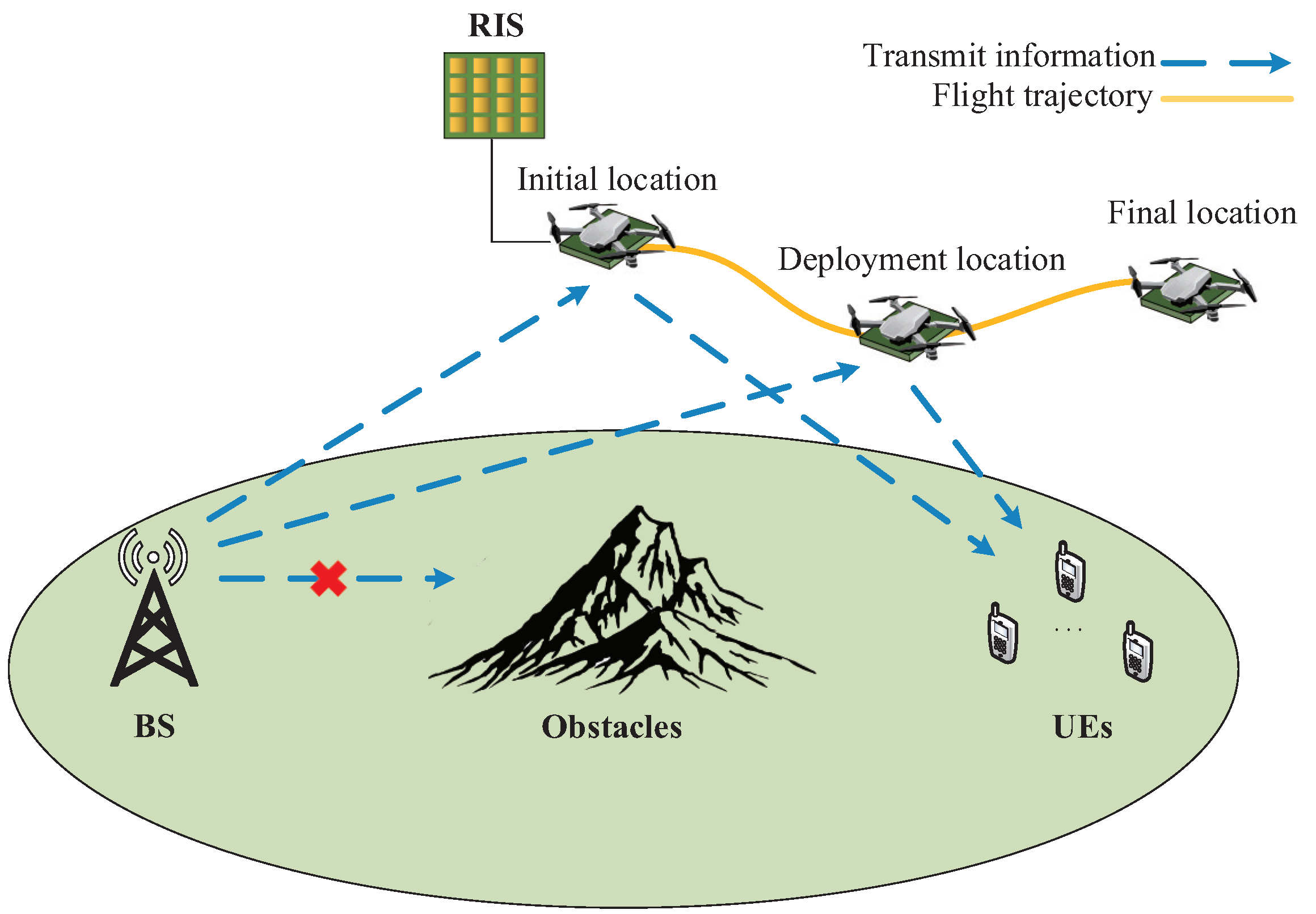
An energy-efficient air-to-ground communication network assisted by the RIS is proposed, in which the RIS-equipped UAV (RIS-UAV) assists the BS to communicate with multiple ground users simultaneously. The RIS-UAV adopts a non-ULA, where the reflecting elements of the RIS do not have a linear relationship among themselves, making the beamforming design of the RIS more flexible. By exploring the full potential of the RIS-UAV, the energy efficiency of the air-to-ground communication network is maximized;
An energy efficiency optimization algorithm based on RIS-UAV deployment is proposed, which is termed the energy-efficient unmanned aerial vehicle deployment (EEUD) algorithm. By using the EEUD algorithm, the RIS phase shifts, the RIS-UAV trajectory, and the BS transmit power are optimized alternately to solve the complex multi-user energy efficiency maximization problem. In addition, we investigate the impact of varied numbers of users, RIS reflecting elements, and BS antennas on system energy efficiency;
The proposed algorithm optimizes the RIS-UAV trajectory to ensure that the instantaneous system energy efficiency is maximized when the RIS-UAV flies along the optimal trajectory in each time slot. In the process of searching for the deployment location, the RIS-UAV maintains a simultaneous association with multiple users and BS to ensure network communications quality. Finally, simulation results are presented to demonstrate that the proposed solution outperforms other benchmark solutions.
The remainder of this paper is organized as follows.
Section 2 describes the system model.
Section 3 presents the EEUD algorithm that optimizes the system energy efficiency, and the simulation results are given in
Section 4. Finally, concluding remarks are drawn in
Section 5. The main symbols defined in this paper are listed in
Table 2.
Notation: In this paper, operators , , , , , and denote the -norm, Frobenius norm, pseudo-inverse, inverse, conjugate transpose, and transpose of a matrix, respectively. stacks all column vectors of matrix to form a vector, which is called the vectorization operator. represents a diagonal matrix with the elements of vector on the main diagonal. The Kronecker product is denoted by ⊗, and is the identity matrix.
3. Energy-Efficient UAV Deployment Algorithm
In this section, the EEUD algorithm is designed to maximize the system energy efficiency by optimizing the RIS phase shifts
, the RIS-UAV trajectory
, and the BS transmit power
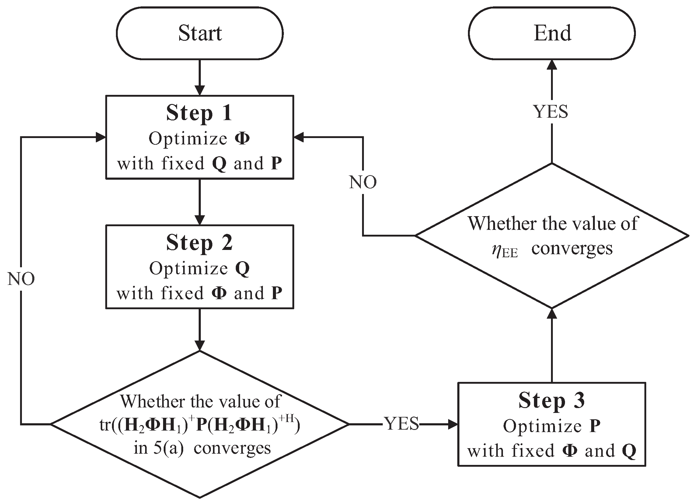
alternately. The process of the EEUD algorithm is shown in
Figure 2. The system energy efficiency in the objective function (5) is denoted by variable
. However, since
,
, and
co-exist in constraint (5a) under the effect of zero-forcing precoding, the values of
and
will affect the range of
and thus the system energy efficiency. Therefore,
and
are optimized alternately first before
, as shown in
Figure 2 for steps 1 and 2. After taking steps 1 and 2 cyclically until the convergence of
in (5a),
and
are fixed in step 3 to optimize
. If the system energy efficiency converges, the EEUD algorithm is terminated and outputs the value of the system energy efficiency and RIS-UAV deployment location. Otherwise, the EEUD algorithm will iterate steps 1–3. The system energy efficiency increases with each iteration, and since (5) is upper-bounded on the feasible set, it eventually converges to a value that approximates the optimal energy efficiency.
The ultimate optimization problem in this paper is the optimization problem , which is to maximize the system’s energy efficiency. In order to solve this problem more efficiently, the objective function (5) will be transformed in the following subsections. The next three subsections describe steps 1–3 of the EEUD algorithm, respectively.
3.1. Step 1: Optimization of the RIS Phase Shifts
In this part, both the BS transmit power
and RIS-UAV trajectory
are fixed, while the RIS phase shift
is optimized. The objective function reduces to a constant
C since
exists only in constraint (5a). The optimization problem
is transformed into
:
Since
only appears in (6a), which means that the optimization of the RIS phase shifts is to make
meet constraint (6a) as much as possible. Decreasing the value of
in (6a) by optimizing
can expand the feasible set of
, which is conducive to increasing the value of the objective function (5). Therefore, constraint (6a) is regarded as the optimization objective to minimize
. Therefore, the optimization goal is transformed into the optimization problem
:
The optimization problem
is non-convex, which is difficult to solve directly. To tackle this challenge, Equation (7) can be reduced to
The BS transmit power
is decomposed in step I, where
. Step II denotes
. Step III is obtained by combining the pseudo-inverse law of matrix products and the property of the Frobenius norm. The vectorization operator
in step IV is to transform a matrix into a vector. Therefore, calculating the Frobenius norm of a matrix becomes equivalent to calculating the norm of a vector. Finally, step V denotes
, and
simplifies the objective function. Then, problem
is transformed into
:
To solve the high-dimensional problem more effectively, we adopt the block coordinate descent (BCD) algorithm, which is a generalization of the coordinate descent. The BCD algorithm optimizes a subset of variables in each iteration, decomposing the original problem into multiple subproblems. in problem can be separated out of N variables denoted by (), where is the -th element of .
3.2. Step 2: Optimization of the RIS-UAV Trajectory
In this part,
and
are fixed when finding the deployment location by optimizing the RIS-UAV trajectory. As a result, the target optimization problem becomes
is the three-dimensional coordinate of the RIS-UAV in the
j-th time slot. Since
is included in both
and
of constraint (10a) and the objective function (10) is a constant, the optimization problem
becomes
where
can be decomposed into
where
is a matrix denoting the distance between the BS and RIS-UAV, and
indicates the distance between the BS and RIS-UAV. Similarly,
can be treated in a similar manner as follows
where
is a matrix denoting the distance between the RIS-UAV and users, and
, denotes the distance from the RIS-UAV to user
k. Therefore, the cascade channel matrix
can further simplify to
Next, the objective function (11) becomes
Then, the optimization problem reduces to
The Hessian matrix in (16) is
where
x and
y are the coordinates of the
x-axis and
y-axis of the RIS-UAV in the Cartesian coordinate system, respectively. The objective function (16) is convex with regards to the coordinates in each time slot, due to the fact that its Hessian matrix is semi-positive definite. Therefore, this problem can be solved by a variety of convex optimization methods, such as the gradient descent method.
3.3. Step 3: Optimization of the BS Transmit Power
In this part, both the RIS phase shifts
and RIS-UAV trajectory
are fixed to optimize the BS transmit power
. The optimization problem of the system is further transformed into the following
:
The convex problem
belongs to the 0–1 fractional programming problem, and it can be solved by using the Dinkelbach algorithm [
29]. The Dinkelbach algorithm is essentially an iterative algorithm, which first starts with a random value, and then approximates the optimal solution iteratively. The process of using the Dinkelbach algorithm to solve problem
is described as follows.
First, the objective function (18) is converted from a fraction into the following equation
Equation (19) is further reduced to
To apply the Dinkelbach algorithm, Equation (20) is converted to the following new function
In the n-th iteration of the Dinkelbach algorithm, function becomes
where
and
are
and
in the n-iteration, respectively.
is
in the (n − 1)-iteration, where
Before the Dinkelbach algorithm is iterated, the initial energy efficiency of the system
with random values is given. Then,
in the first iteration is
Next, the value of is maximized by adjusting the BS transmit power to user k, which falls under the category of linear programming problems. After the maximum of is obtained, , is used to update to . Similar operations are repeated in subsequent iterations. When the solutions in each iteration converge, the value of is taken as the optimal energy efficiency of the system.
3.4. Complexity Analysis
For the EEUD algorithm, its complexity is mainly determined by the number of iterations of its outer layer, denoted by
. The complexity of optimizing the RIS phase shifts depends on the number of iterations of the BCD algorithm, denoted by
. Note that the complexity of the convex problems is of polynomial complexity, and the maximum complexity is the fourth power of the number of optimized variables [
30]. Since
N variables of the RIS are divided into multiple subsets, the complexity of each subset is
, where
is the number of variables contained in the
s-th subset and
. The number of iterations between subsets is represented by
. Thus, the complexity of the RIS phase shifts optimization by using EEUD algorithm is
.
For the RIS-UAV trajectory optimization, the iteration times of the gradient descent method is required in each time slot, and depends on the partial derivatives and the step size of the objective function. Partial derivatives of the objective function with respect to and are calculated separately, and times are required in each time slot. For S time slots, the gradient descent algorithm has a complexity of . Therefore, the complexity of alternating and is .
Optimizing the BS transmit power depends on the iteration times of the Dinkelbach algorithm, denoted by . Since the convex problem solved by the Dinkelbach algorithm is the power allocation for K users, the complexity of the BS transmit power optimization is , where .
In conclusion, the overall complexity of the EEUD algorithm proposed in this paper can be shown as
4. Simulation Results
Figure 3 illustrates the 3D coordinate system of the RIS-assisted multi-user air-to-ground communication network, and the system parameters are given in
Table 3 and
Table 4, where
is the location of the BS. The values of
,
,
,
,
and
in
Table 3 are taken from [
7]. The values
B,
,
and
in
Table 3 are from [
22]. The simulation is conducted in MatlabR2021a, and the argmax problem in this paper is solved by the
fmincon function in Matlab, which is a powerful tool for solving extreme values of nonlinear multivariate functions.
To validate the efficacy of the EEUD algorithm, three standard deployment locations are established, which are called benchmark locations 1, and 2. Benchmark location 1 (100 m, 50 m, 100 m) and benchmark location 2 (100 m, −50 m, and 100 m) are located on the perpendicular bisector between the initial location and the final location.
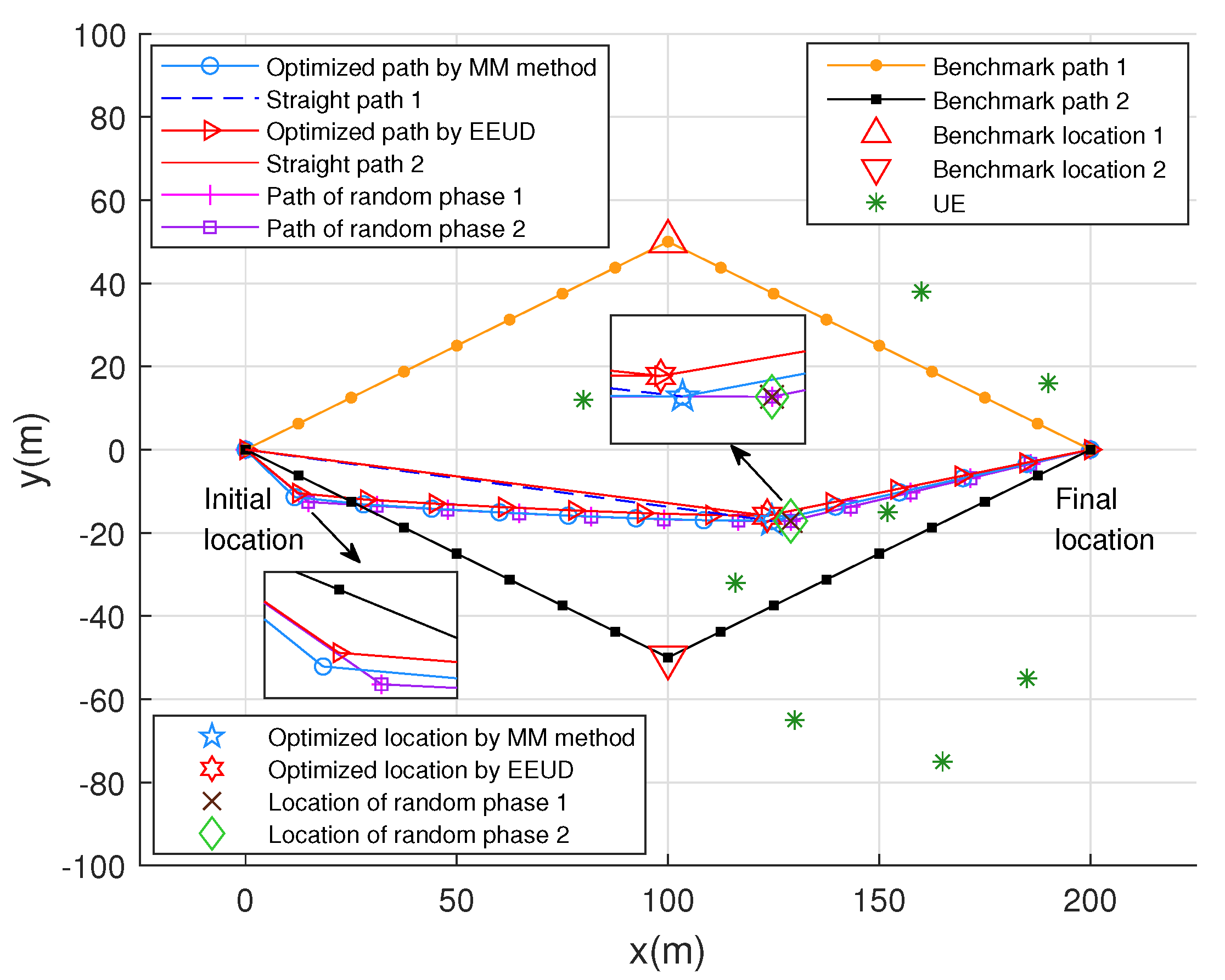
Figure 4 shows eight flight trajectories of the RIS-UAV. The deployment locations of the RIS-UAV in these eight paths are relatively independent and different, and the RIS-UAV will fly directly to the destination after completing the communication task at the different deployment locations. One path is the trajectory that the RIS-UAV uses the EEUD algorithm to find the quasi-optimal deployment location, whereas the other path is to use the majorization-minimization (MM) method in [
18] to optimize the RIS phase shifts. The deployment location is the same for both the optimal path and the straight path. The difference between them is that the straight path does not optimize the trajectory of the RIS-UAV during the flying process, and the RIS-UAV keeps a straight line to the deployment location. As shown in
Figure 4, when the RIS phase shifts are not optimized and fixed to a random value, the deployment location of the RIS-UAV is offset from the quasi-optimal location. The reason is that the EEUD algorithm does not optimize
in this case, and
do not need to be optimized alternately with
, which results to the offset of deployment location. In addition, the paths of random phase 1 and random phase 2 almost coincide. The reason for this phenomenon is that when
is not optimized, it is only necessary to minimize the objective function (11) when optimizing step 2 in the EEUD algorithm. Therefore, the optimization of the RIS phase shifts has a certain influence on the RIS-UAV trajectory and deployment location.
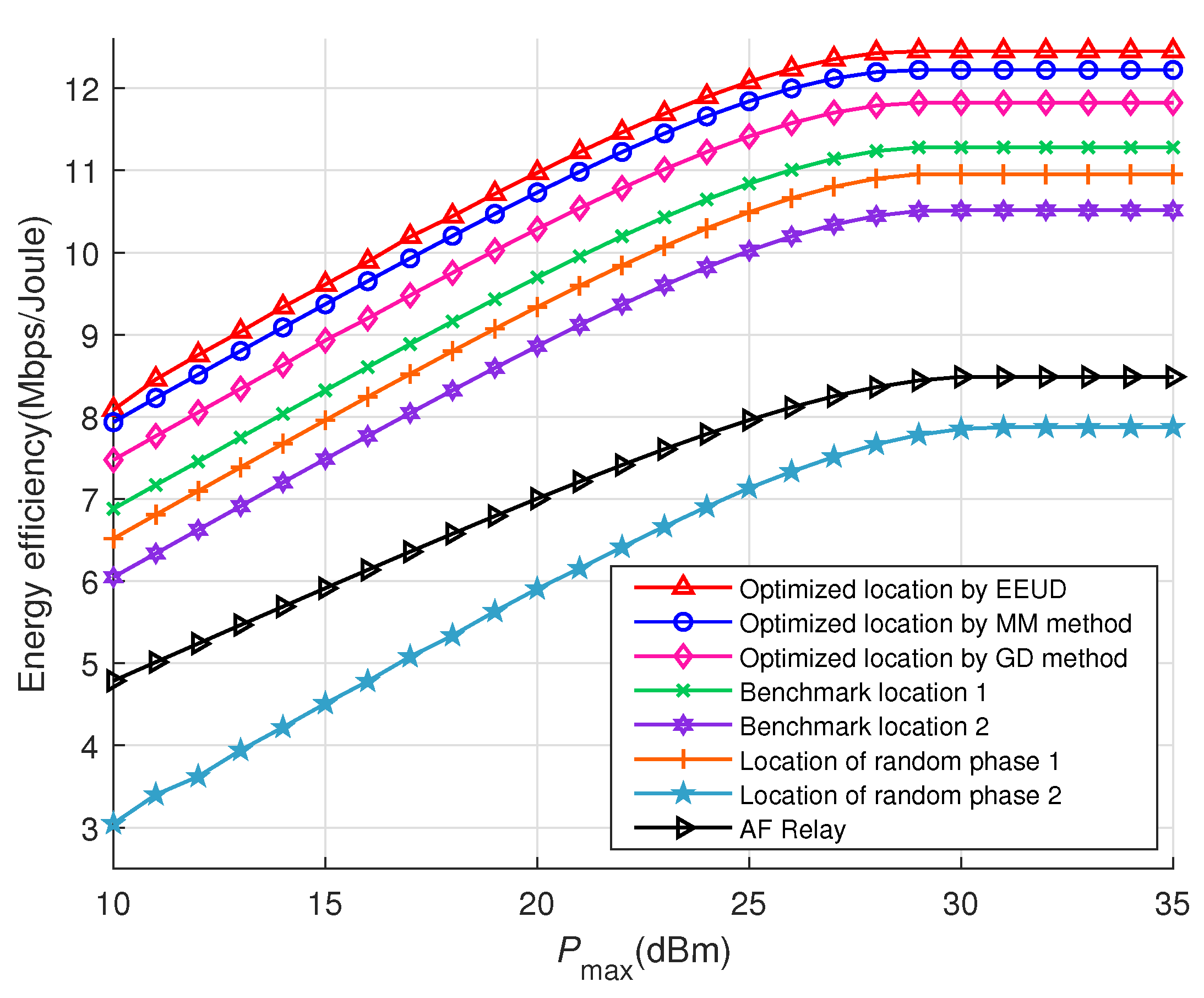
Figure 5 shows the energy efficiency versus the maximum threshold
, where the RIS-UAV is deployed at different locations and the BS transmit power
is optimized. All curves are optimized for the RIS phase shifts
except for the location of random phase 1 and random phase 2. For improving energy efficiency, the EEUD algorithm is better than both the MM method in [
18] and the gradient descent (GD) method in [
7], where [
7] employs the GD method to optimize the RIS phase shifts. It is clear that when RIS-UAV is deployed at the location by using the EEUD algorithm, its energy efficiency is significantly higher than that of other deployment locations. In addition, the energy efficiency levels off around the
taken at 30 dBm. The reason is that the variable
is contained in both the numerator and the denominator of the objective function (5). For the numerator,
exists in the logarithmic function. According to the characteristics of the logarithmic function, its growth rate will gradually decline. For the denominator, its value grows linearly according to
. When the growth rate of the numerator is reduced to the same rate as that of the denominator, the system energy efficiency reaches a peak, which is the inflection point in
Figure 5. Then, the BS will maintain
at the inflection point to avoid reducing the system’s energy efficiency. The different curves in
Figure 5 have different inflection points, which are related to the RIS phase shifts
and the RIS-UAV deployment location, as they together constrain
to satisfy the constraint (5a). It can be seen that when
= 30 dBm, all curves reach their maximum values. Therefore, in the subsequent
Figure 6,
Figure 7,
Figure 8,
Figure 9 and
Figure 10, we set the value of
to 30 dBm. For the random phase, the maximum energy efficiency will be higher or lower than that of the RIS-UAV at benchmark location 1 or benchmark location 2, which is due to the different RIS phase shifts. Furthermore, the effect of the RIS and AF relay in improving system energy efficiency has been compared. To make the comparison more fairly, the number of AF relay antennae is kept the same as the number of RIS reflecting elements
N, and the AF relay equipped on the UAV is deployed at the same quasi-optimal location as that of the RIS-UAV. As shown in
Figure 5, compared with the AF relay, the RIS has a significant improvement in energy efficiency, which can provide up to 145% energy efficiency improvement.
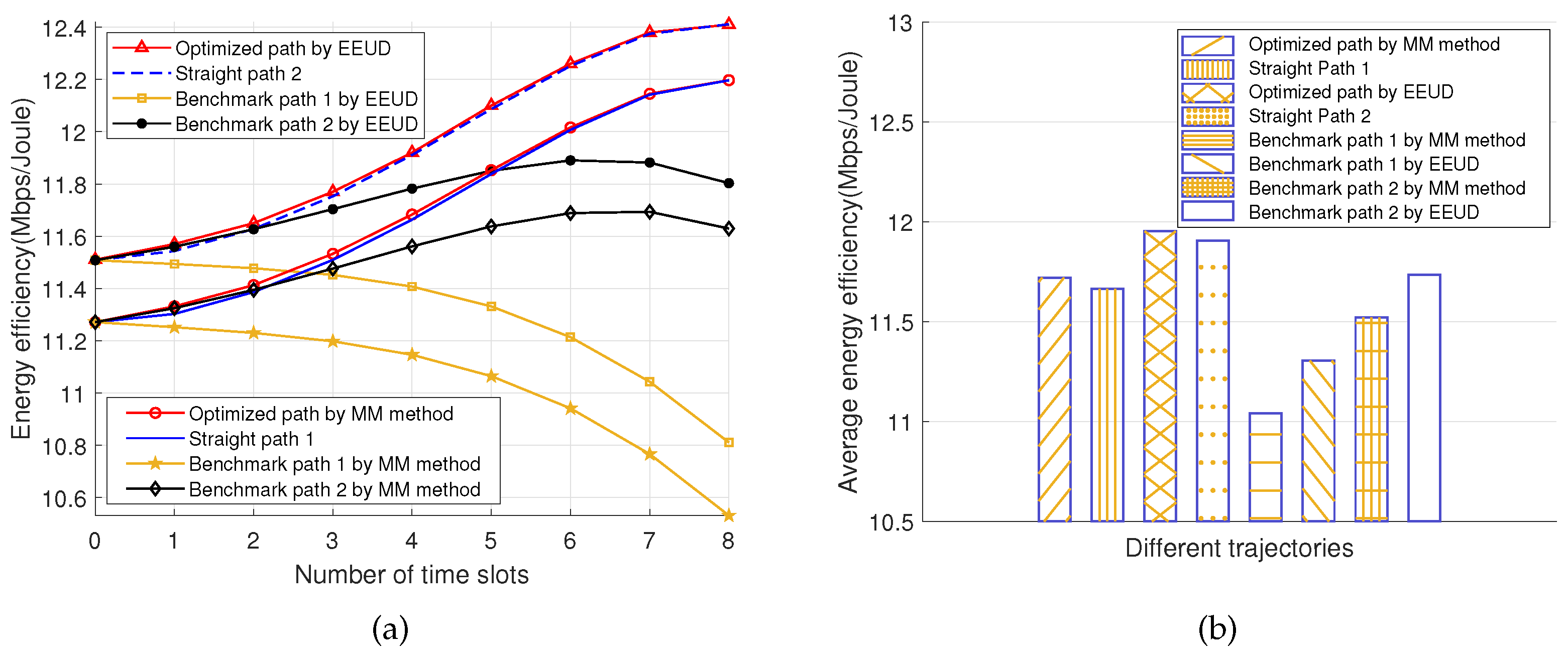
Figure 6a characterizes the instantaneous system energy efficiency in each time slot and its average value in the full time slot when RIS-UAV follows different flight trajectories. The RIS phase shifts
and BS transmit power
in each time slot are optimized. For the instantaneous system energy efficiency,
Figure 6a shows that when the RIS-UAV flies to the deployment location along the optimal path, the energy efficiency in each time slot is higher than that of the RIS-UAV flies along any other flight path. The reason is that the RIS-UAV follows the optimal path and can ensure high energy efficiency in each time slot. After the RIS-UAV reaches the deployment location, the optimal path and the straight path coincide, and their energy efficiency gradually becomes overlapped. For benchmark path 1, its energy efficiency rises initially and subsequently falls. The reason behind this is that the distance between the RIS-UAV and deployment location is inversely proportional to the system’s energy efficiency. Increasing the distance between the RIS-UAV and deployment location results in the decreased energy efficiency of the system. As shown in
Figure 4, when the RIS-UAV flies along benchmark path 1, the distance between the RIS-UAV and deployment location first decreases and then increases. Therefore, for benchmark path 1, the system energy efficiency rises initially and subsequently falls. For benchmark path 2, the system energy efficiency keeps dropping because the RIS-UAV keeps moving far away from the deployment location during the flying path.
Moreover, the average energy efficiency of the RIS-UAV across all time slots along each flight path was calculated in
Figure 6b. The average energy efficiency of the RIS-UAV flying along the optimal path is higher than that of any other path. The simulation results further verify that RIS-UAV flying to a quasi-optimal location along the optimal path is the best way to improve the system’s energy efficiency.
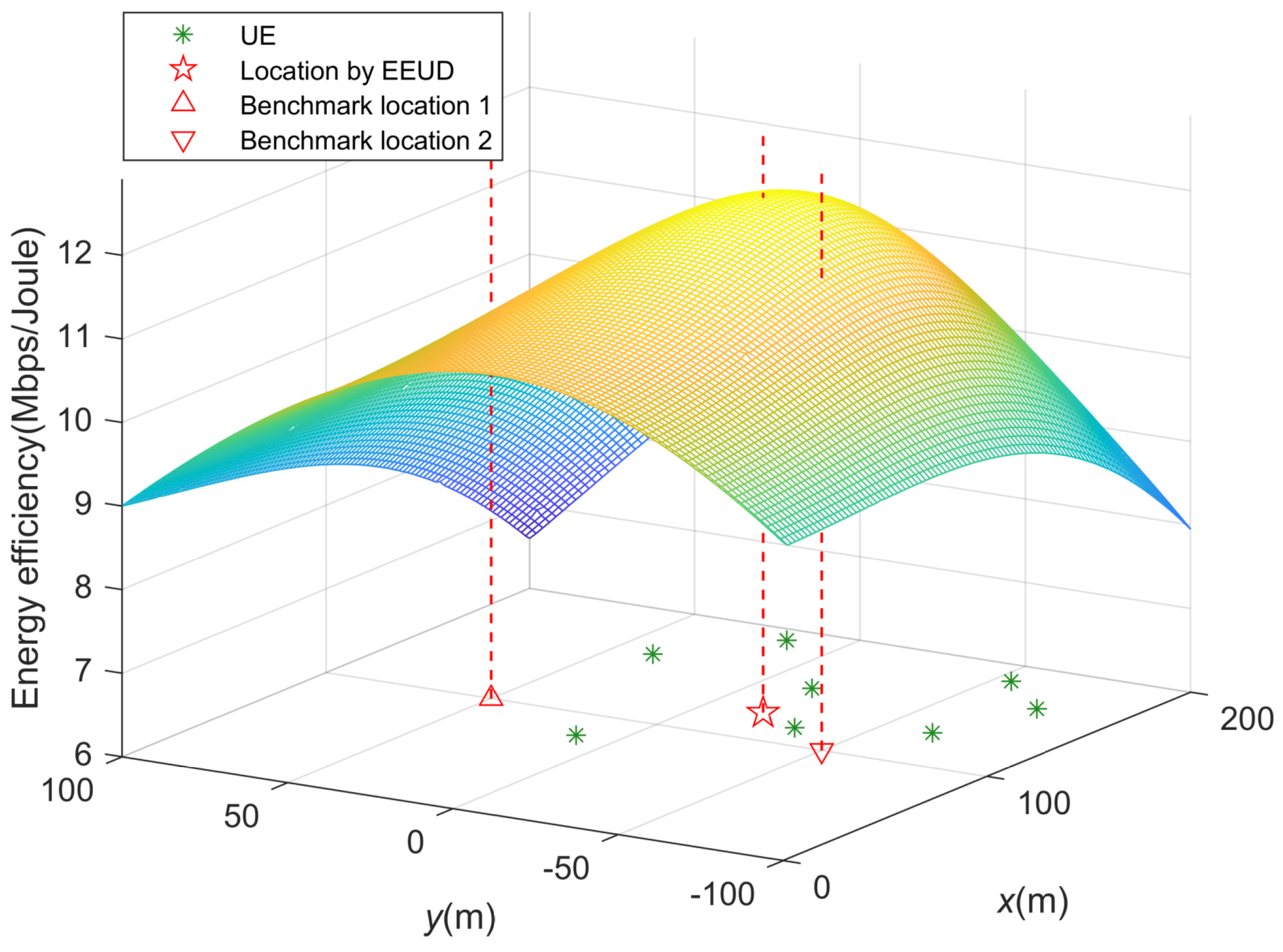
In order to explore the impact of different RIS-UAV deployment locations on system energy efficiency, we focus on the entire coordinate system, as shown in
Figure 7. Assuming that each point coordinates on the entire coordinate system can be used as the deployment location of the RIS-UAV, and the RIS phase shifts
and BS transmit power
for each point coordinate are optimized to show the upper bound of the system energy efficiency. By combining the maximum energy efficiency of all the point coordinates on the whole coordinate system, a three-dimensional figure can be obtained that can visually reflect the impact of the RIS-UAV deployment location on system energy efficiency, as given in
Figure 7. It is obvious that the system energy efficiency is almost the best when the RIS-UAV is at the quasi-optimal location identified found by the EEUD algorithm.
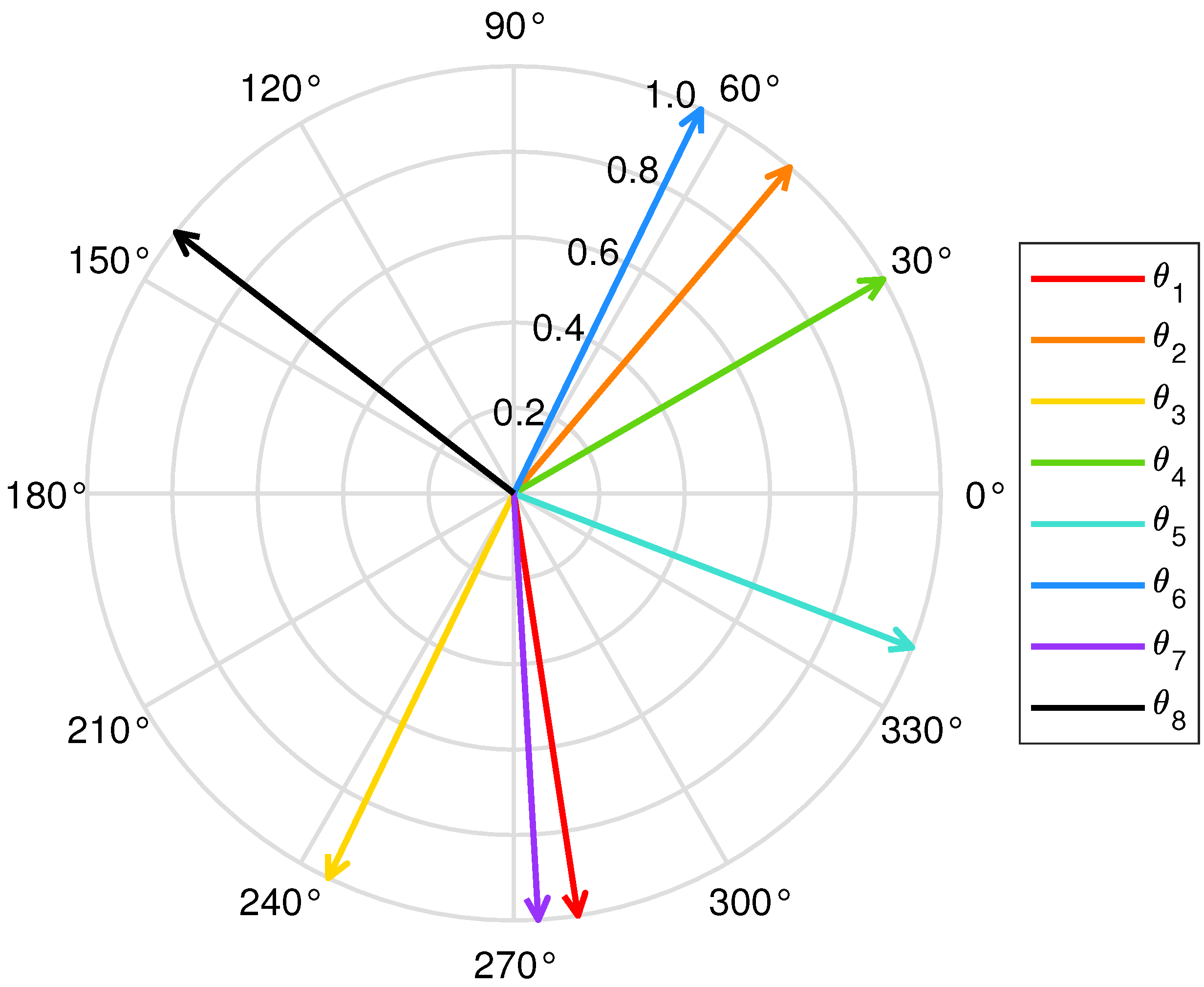
The final phase distribution across the RIS phase shifts
is shown in
Figure 8. As mentioned before, the RIS phase shifts are denoted by matrix
, where
corresponds to the phase of the
n-th RIS reflecting element. The phase of each RIS reflecting element has a modulus of 1, which is determined by the characteristics of the RIS. The RIS does not change the amplitude of the reflected signal, but rather its phase shift. However, the traditional ULA RIS requires a fixed angle between each RIS reflecting element [
15]. Compared with the ULA RIS, it can be clearly seen from
Figure 8 that there is no linear relationship between each RIS reflecting element of the non-ULA RIS adopted in this paper, which makes the beamforming design of the RIS more flexible.
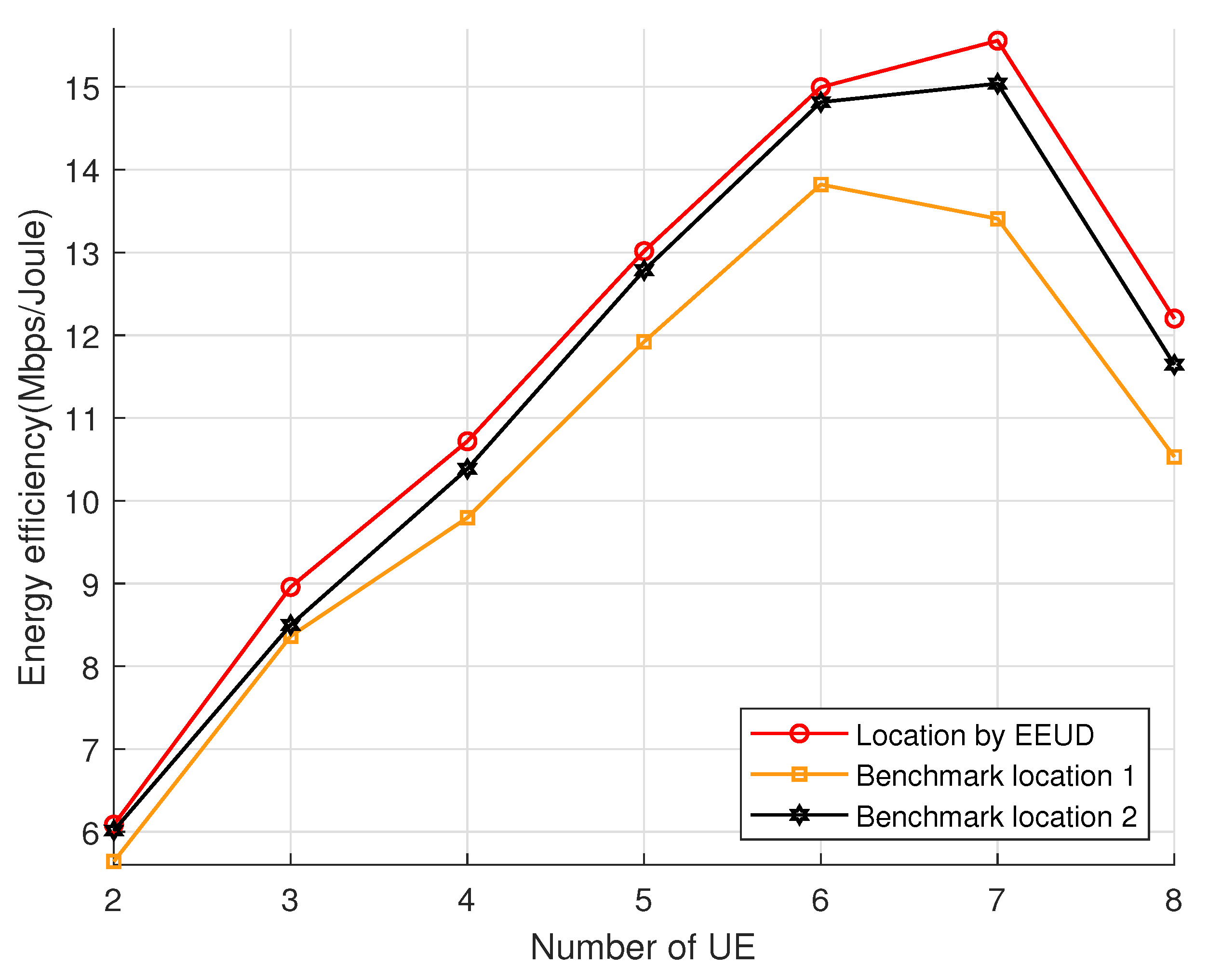
Figure 9 investigates the impact of different numbers of users on system energy efficiency, where the RIS phase shifts
and BS transmit power
are optimized. The RIS-UAV is deployed at the three different locations, and users are added to the system according to the coordinate in
Table 4. It is obvious that the system’s energy efficiency increases with the user numbers at the beginning. However, when the user numbers further increase to a certain level, adding new users will instead reduce the system’s energy efficiency. The reason is that the system energy efficiency is the ratio of the sum rate to the total power consumption, and the growth rate of the total power consumption is faster than that of the sum rate. Adding new users will bring additional circuit power consumption
to the system. When users continue to increase past the user numbers that can be accommodated by the system’s energy efficiency, it will cause a decrease in energy efficiency. In addition, compared with the quasi-optimal location, and benchmark location 2, when the RIS-UAV is deployed at benchmark location 1, the upper limit of the user number that can be accommodated by the system energy efficiency is small. The reason is that the benchmark location 1 is far away from the quasi-optimal location, resulting in large path loss during signal transmission, and the large path loss reduces the value of energy efficiency. Therefore, optimizing the deployment location of the RIS-UAV can increase the upper bound of the user numbers that the system can accommodate.
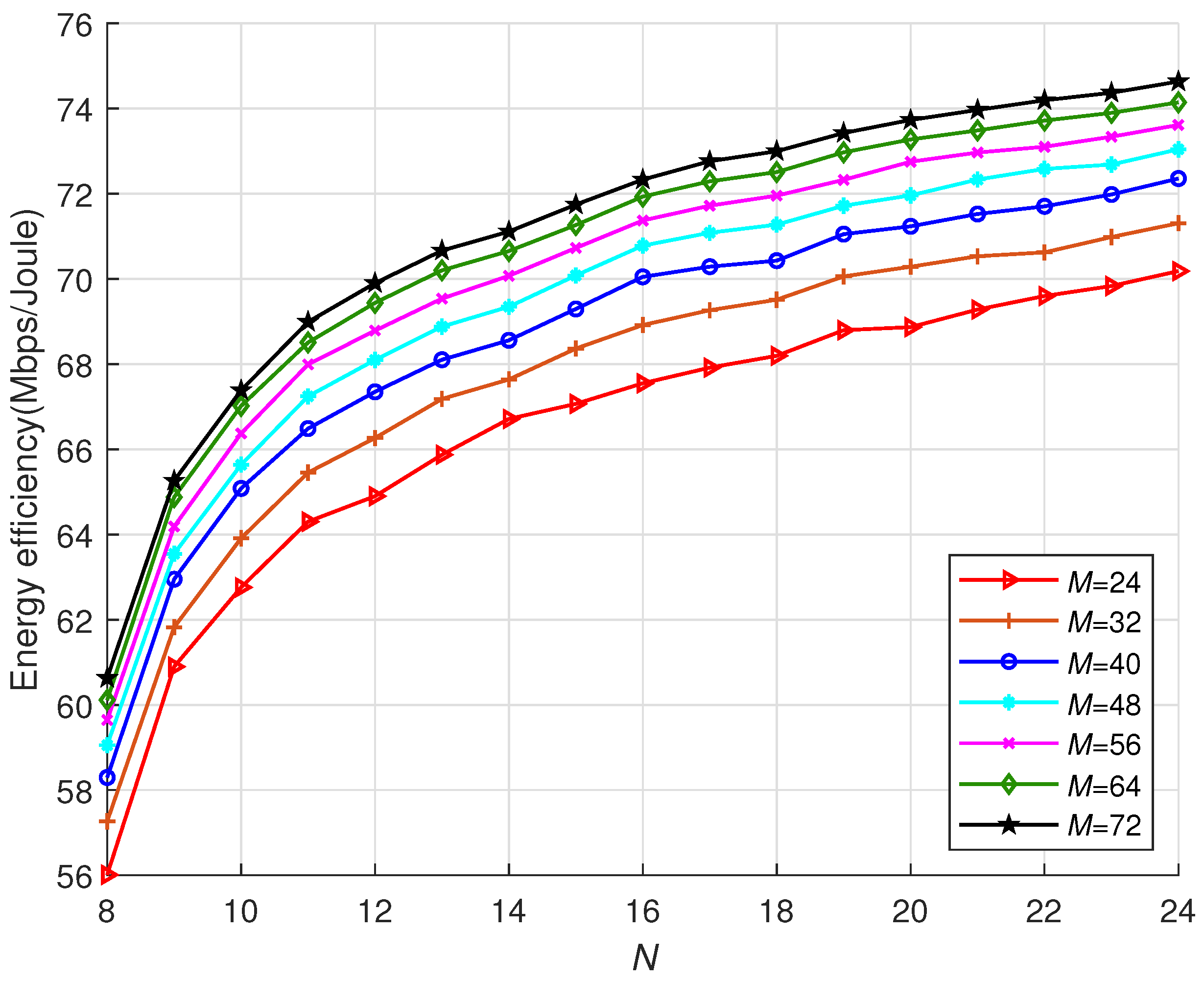
Figure 10 characterizes the effect of different numbers of BS antenna
M and RIS reflecting element
N on the system energy efficiency, where
is 30 dBm. On the one hand, raising
N improves the system energy efficiency since raising
N can increase the channel numbers, and thereby improving the SNR. Nevertheless, when
N continues to rise, the upward trend of the system energy efficiency begins to decelerate. The reason is that increasing SNR is nonlinear with regards to
N, and the power consumption of RIS
will rise with increasing
N. On the other hand, when
N is fixed, the increase in
M can improve the system’s energy efficiency. This is because increasing
M can improve the SNR. Because the increase in SNR is non-linear in relation to
M, as
M increases, the increasing trend of energy efficiency slows down progressively. As a result, the values of
M and
N should be chosen reasonably. If
M or
N is too large, the benefits of the system are limited and it will increase the cost and complexity of the hardware.
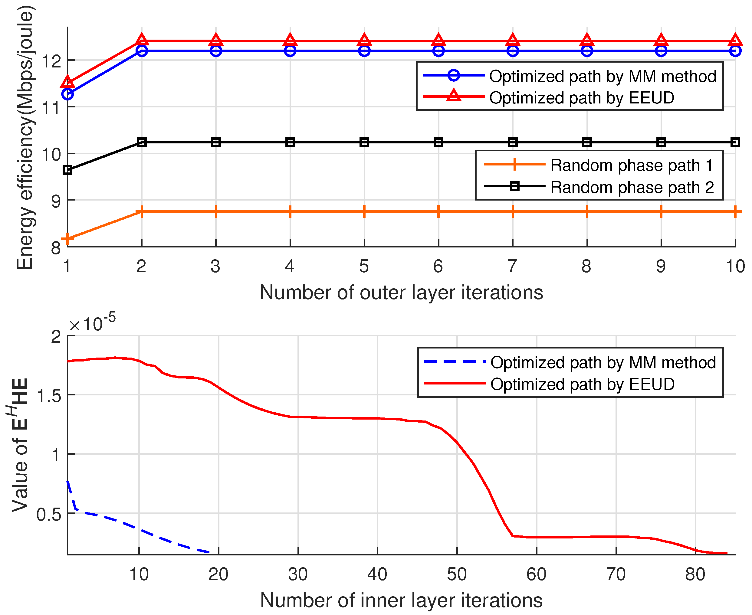
The convergence iterations of the EEUD algorithm are shown in
Figure 11, including the number of the outer and inner layer iterations, where the inner layer refers to the RIS phase shifts optimization and the outer layer iteration executes steps 1–3 in the EEUD algorithm. It is clear that the outer layer of the EEUD algorithm converges quickly, and its improvement in system energy efficiency outperforms other solutions.


