Article

Vehicle-to-Vehicle Based Autonomous Flight Coordination Control System for Safer Operation of Unmanned Aerial Vehicles

Wireless Systems Laboratory, Wireless Networks Research Center, Network Research Institute, National Institute of Information and Communications Technology (NICT): 3-4, Hikarino Oka, Yokosuka 239-0847, Kanagawa, Japan
*
Author to whom correspondence should be addressed.
Drones 2023, 7(11), 669; https://doi.org/10.3390/drones7110669
Submission received: 23 September 2023 / Revised: 2 November 2023 / Accepted: 8 November 2023 / Published: 9 November 2023
(This article belongs to the Special Issue UAVs Communications for 6G)

Abstract

:
The exponential growth of unmanned aerial vehicles (UAVs) or drones in recent years has raised concerns about their safe operation, especially in beyond-line-of-sight (BLOS) scenarios. Existing unmanned aircraft system traffic management (UTM) heavily relies on commercial communication networks, which may become ineffective if network infrastructures are damaged or disabled. For this challenge, we propose a novel approach that leverages vehicle-to-vehicle (V2V) communications to enhance UAV safety and efficiency in UAV operations. In this study, we present a UAV information collection and sharing system named Drone Mapper ® , enabled by V2V communications, so that UAVs can share their locations with each another as well as with the ground operation station. Additionally, we introduce an autonomous flight coordination control system (AFCCS) that augments UAV safety operations by providing two essential functionalities: UAV collision avoidance and UAV formation flight, both of which work based on V2V communications. To evaluate the performance of the developed AFCCS, we conducted comprehensive field experiments focusing on UAV collision avoidance and formation flight. The experimental results demonstrate the effectiveness of the proposed system and show seamless operations among multiple UAVs.

1. Introduction

Non-terrestrial networks (NTN) are an effective solution that can provide wireless communication services over uncovered or under-served areas towards Beyond 5G [1]. NTNs are a communication platform for connecting devices in various locations ranging from the sky to seas and space, through different vehicles such as satellites, aircraft, and ships. In particular, when unmanned aerial vehicles (UAVs), also known as drones, are employed as flying wireless base stations, it becomes possible to construct wireless networks in the air, and various relevant research has been reported in this research area [2].
In recent years, the development and applications of UAVs has shown rapid growth. Because the UAVs have very outstanding mobility that is not limited by all kinds of terrain, they can provide high convenience and good accessibility in scenarios such as package delivery in isolated areas or disaster investigation [3,4]. As a result, many new wireless technologies, such as Internet of Things (IoT), can be improved or extended using UAVs. However, as the development of UAVs is highly growing, the safety of UAV operations becomes an emerging issue worldwide.
For safe UAV operation issues, it is essential to develop a suitable and effective UAV control system, also called an unmanned aircraft system (UAS) [5,6,7,8]. However, for multiple UAV scenarios, awareness of neighboring flying vehicles while keeping a safe enough distance among flying objects is a very tough task. Especially for UAV applications nowadays, the flying distances for UAVs are usually very long and it is almost impossible to confirm the flying circumstance with human eyes, which makes a great threat to the UAV flight safety operation issues. Hence, a mechanism to automatically perform UAV awareness and information sharing is very important for modern UAS applications.
In traditional approaches, UAS relies on existing commercial communication networks, such as cellular or satellite networks, to enable the implementation of UAS traffic management (UTM) functions for UAVs [9,10,11,12]. However, in critical UAV scenarios, such as large-scale disasters, it is common for the communication network infrastructure to be damaged or disabled, which makes UTM ineffective. As a result, UAVs are forced to operate in high-risk conditions, so that their safety and effectiveness are hardly guaranteed.
Considering that existing cellular networks are suitable only for terrestrial communication and have limitations in supporting aerial communications, the authors of [13] presented a future perspective on 6G-enabled UTM ecosystems, with a focus on non-terrestrial features, including aerial and satellite communication. Similarly, the authors of [14] identified the most promising 6G enablers for UAV communication and examined the peculiarities of direct device-to-device (D2D) communications in the sky. More recently, to address collision issues, [15] evaluated a reduction in separation distances between UAVs using Wi-Fi- and Bluetooth-aided communication techniques through simulations. The topic of integrated systems based on wireless sensor networks and UAVs has also sparked extensive discussion in [16]. In [17], D2D communications extended to UAV systems are considered important concepts for the future. In [18,19], the authors reveal the potential applications of UAV-assisted communications with AI technologies in 5G/6G systems. Undoubtedly, the most significant challenge at present is how to achieve UAV communication without any infrastructure support.
Given the aforementioned descriptions, addressing the sharing of UAV locations within the neighborhood airspace without cellular or other existing networks becomes crucial for ensuring UAV safety. In our study, this can be achieved through the implementation of vehicle-to-vehicle (V2V) communications, enabling UAVs to share their locations with each other as well as with the ground operation station. Furthermore, maintaining a safe distance between flying vehicles is essential to prevent potential collisions. This facilitates the recognition and exchange of location information for each UAV, which serves as the foundation for developing applications aimed at enhancing UAV safety through the utilization of shared location information with V2V communications [20,21]. By implementing these mechanisms, the risks associated with UAS can be mitigated, ensuring safer and more efficient operations in various domains.
In this paper, we develop a system for location awareness and sharing of UAVs named “Drone Mapper ® ” [22]. To enable these functions, the system utilizes a V2V communication with low-power wide-area (LPWA) functionality operating in the 920 MHz band for global navigation satellite system (GNSS)-based location information sharing. The LPWA is an emerging wireless network technology designed for communication ability among low-power, especially battery-powered, devices over large geographical areas [23]. Since the AFCCS sensors and end devices in the UAS are mainly battery-based and power-limited communication devices, LPWA works as the solution to optimize the energy consumption of the end devices in the network [24,25]. In addition, because the wireless technology adopted in the proposed system does not need cellular infrastructures, it can work under some tough conditions without good infrastructure such as countryside circumstances or places suffering severe disasters.
Furthermore, building upon Drone Mapper, we also develop an autonomous flight coordination control system (AFCCS) to enhance UAV safety operations. The AFCCS provides two essential functionalities for multiple UAV applications: UAV collision avoidance and UAV formation flying. To assess the effectiveness of our proposed method, we conduct field experiments specifically targeting these functionalities, and the experiments are designed to thoroughly evaluate the performance of our developed system and its associated methods.
The rest of this paper is organized as follows. The system description for this study is provided in Section 2. The proposed methods for flight coordination control are introduced in Section 3. Then, we conduct field experiments to evaluate the proposed methods and system in Section 4. Finally, we provide some concluding remarks in Section 5.

2. System Description

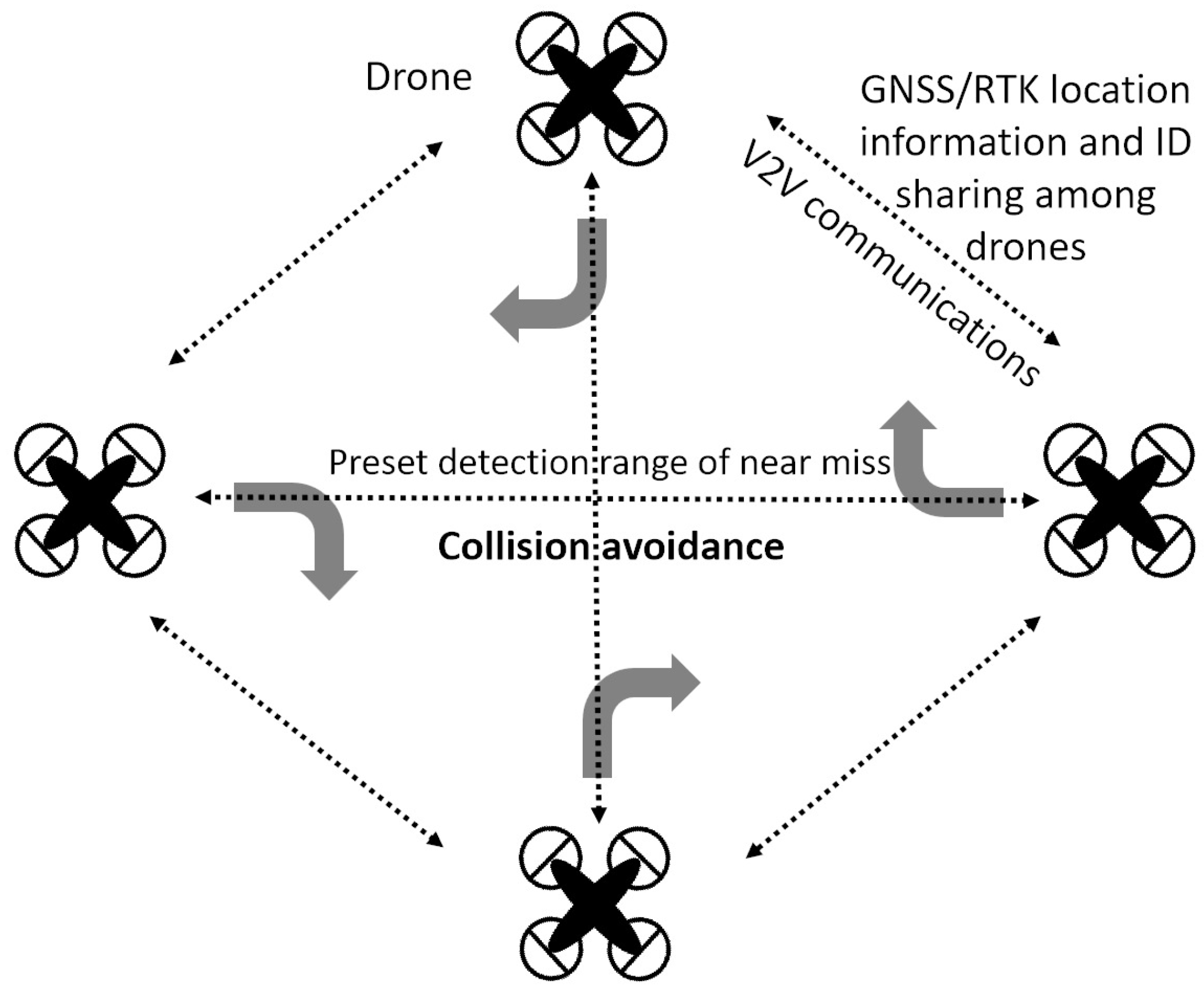
In the proposed system, there are two essential functions for UAV location awareness and sharing, which are the acquisition of UAV location using GNSS and information sharing via communication among the flying vehicles. According to the concept shown in Figure 1, the system can be set up in UAVs and manned flying vehicles to communicate with each other. Furthermore, there is a ground station that optionally works for monitoring the flying vehicles if this functionality is required. With this system, all the location information of the flying vehicles can be measured, shared, and managed.
For the transmissions among UAVs, LPWA technology with 920 MHz is adopted in our developed system. Although there are some other possible candidates for V2V communications, such as Bluetooth or Wi-Fi in the 2.4 GHz band, these technologies work within a very short communication distance in some countries and may be affected by the existing wireless systems. Therefore, these technologies are not proper for communicating with manned aircraft. In this system, we use Frequency Shift Keying (FSK) modulation and LoRa (long-range) modulation with 920 MHz for transmissions. LoRa is widely used in LPWA technologies that can robustly transmit the shared information among UAVs in a very power-saving fashion.
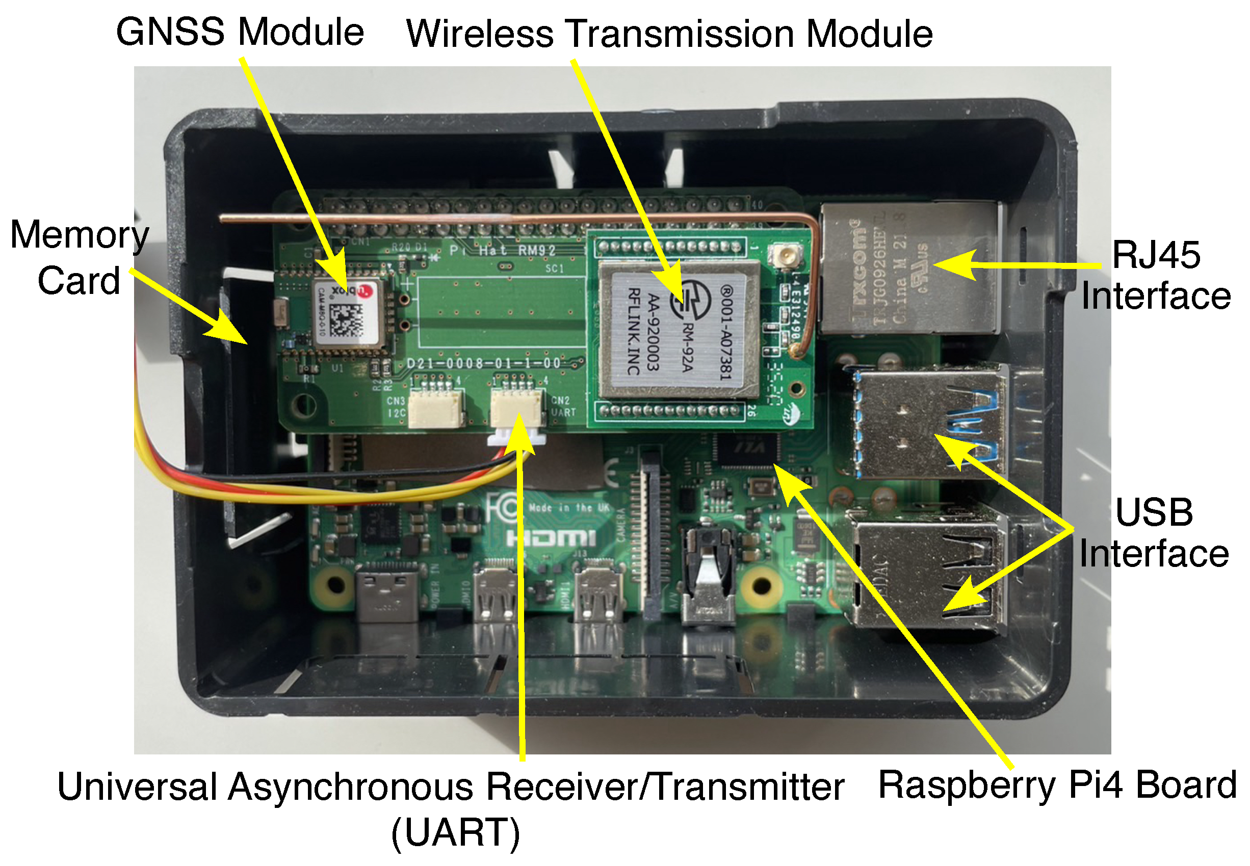
Based on the above V2V communication system, we develop an AFCCS that can be equipped in each UAV to expand its functionality. The AFCCS primarily consists of three key components: a wireless data collection and transmission device [21], a flight coordination control device developed based on Raspberry Pi (a series of small, low-cost, single-board computers designed and developed by the Raspberry Pi Foundation, a UK-based charity organization), and a flight controller. An illustration of the AFCCS device implementation is shown in Figure 2. In the following subsections, more detailed explanations about these components are provided.

2.1. Data Collection and Transmission Unit (Drone Mapper Device)

A system block diagram and a hardware photograph of our developed Drone Mapper device are shown in Figure 3 and Figure 4, respectively. The Drone Mapper device we developed can provide broadcast-based location information sharing between UAVs and the operators, as well as information sharing among UAVs and manned aircraft flying in the surrounding airspace, to realize safe operation for flying vehicles. This device includes the following features. First of all, the UAV communication system is based on a simple V2V broadcasting protocol without the need for network infrastructure such as a base station (BS) or access point (AP), so that it can be implemented with high flexibility. Moreover, the system uses the license-free 920 MHz band for telemetry, telecommand, and data transmission radio equipment following the Association of Radio Industries and Businesses (ARIB) standard of Japan [26]. In addition, the system can cover beyond visual line of sight (BVLOS) UAV communications with multi-hop relay communication, which contains up to two hops. Finally, the system can operate a remote information sharing system via the network by sending UAV information to UTM internet services.
Regarding the detailed information of the Drone Mapper device, in Figure 3, we show the concept of designing the UAV location and ID information-sharing system. From this figure, it can be seen that there are three types of data to be collected, which are environment data obtained with sensors or a calculator, location data obtained using GNSS, and aircraft information. The three types of data are stored in the Drone Mapper’s memory and can be exchanged among the helicopter, UAV, and ground monitoring station via the license-free 920 MHz band with LoRa communication. Note that the Drone Mapper device is capable of transmitting and receiving signals via a single communication antenna when it is implemented.
In the current version of the Drone Mapper device, we select LoRa and FSK modulation techniques for wireless data transmission. LoRa modulation is adopted mainly because of the smaller transmission power and longer transmission distance, while its transmission rate is up to max 37.5 kbps. On the contrary, FSK modulation is adopted for achieving higher transmission rates (max. 300 kbps) than the LoRa and thus improve the efficiency of data exchange. The related specifications for the developed Drone Mapper device are summarized in Table 1.
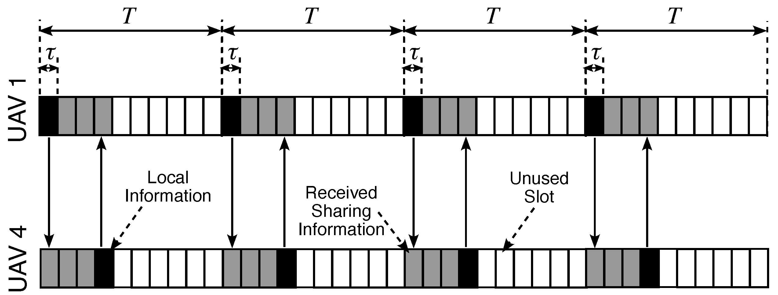
In the considered system, the local and shared information of the UAVs is transmitted and received using wireless transmission modules. In Figure 5, we provide an illustration of the frame structure for the V2V communication protocol. To deal with interference issues, we adopt the time division multiple access (TDMA) method for the frame structure design. Specifically, we divide a frame equally into N time slots τ 1 , , τ N and let τ n = τ n { 1 , , N } . UAV n occupies the time slot τ n to transmit its local information, including position, velocity, etc. Other time slots except τ n are not used by UAV n during the flight process. As a result, each UAV shares its local information with a duration T = τ N , and interference among UAVs can be ignored under the assumption of no channel delay and perfect transmitting synchronization. Certainly, interference among slots generally occurs and results in packet loss, which reduces the reliability of information sharing among UAVs. Fortunately, in general cases, UAVs operate under good channel conditions, and the interference would not be a severe issue.

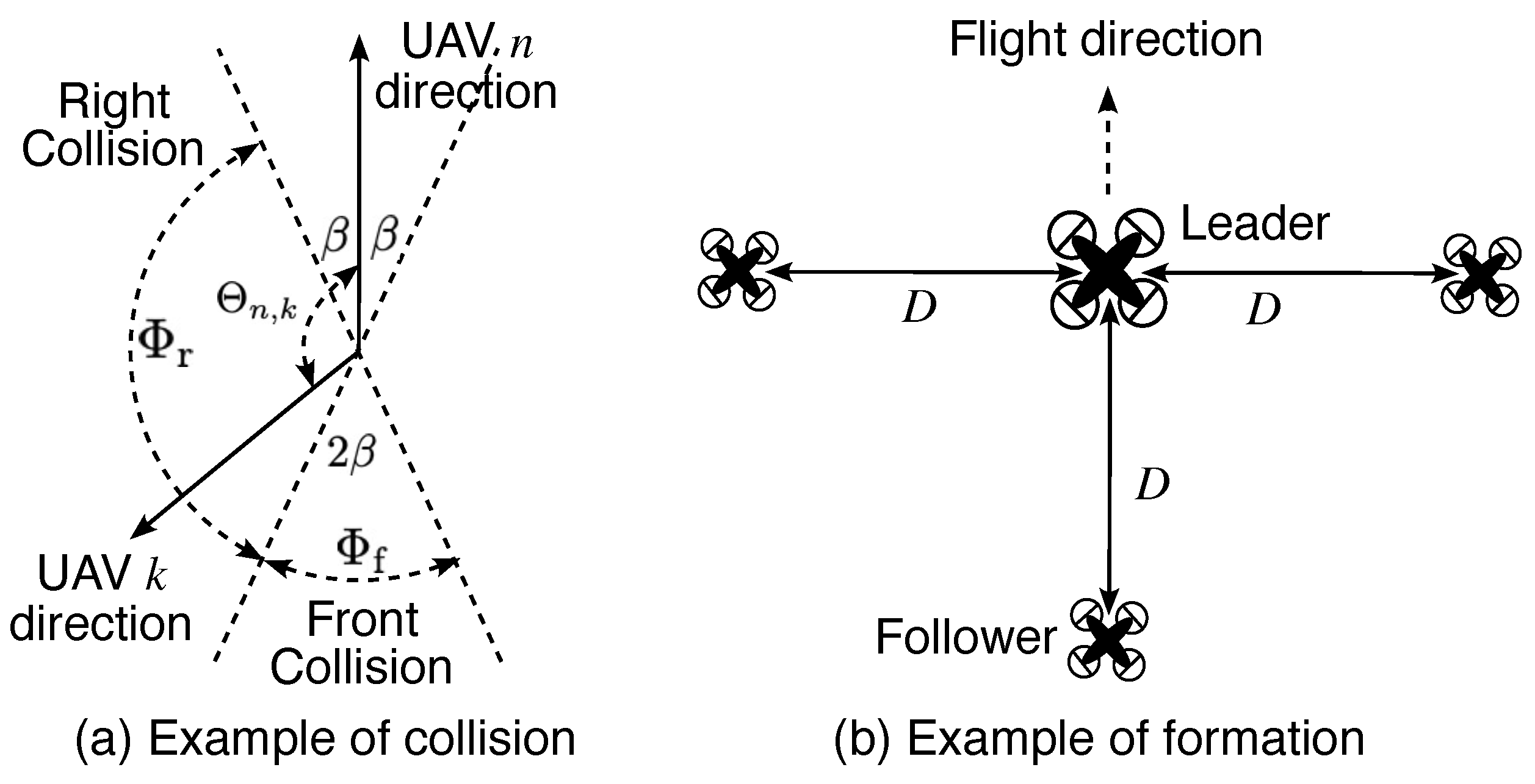
2.2. Flight Coordination Control Unit

For the flight coordination control unit, there are two main tasks: calculation and conversion tasks. The calculation task includes operating different algorithms and using data from the Drone Mapper device to calculate the basic parameters required for the UAV to perform its flight missions. The parameters include the flight speed, flight direction, destination coordinates, etc. The conversion task operates conversion of the data parameter output from the previous step into commands that can be recognized and executed by the UAV, and then these commands are sent to the flight controller. Different algorithms need to be designed and implemented for different flight missions in this unit. This is a highly creative and customized process.
In general, a multiple input–output (I/O) algorithm implemented in this unit can be mathematically expressed by
O 1 , O 2 , , O M = A n I n , 1 , I n , 2 , , I n , N ,
where A n presents the designed algorithm performed by UAV n for the flight operations, including but not limited to collision avoidance and flight formation. I n , k for k { 1 , , N } denotes the received shared information sent from UAV k to UAV n , and includes longitude, latitude, etc. In the present systems, I n , k can be further expressed by
I n , k = α n , k , t n , k , x n , k , y n , k , z n , k , v n , k , θ n , k , r n , k ,
where α and t denote the identification and flight time. x, y, and z are defined as the longitude, latitude, and altitude of the UAV. v and θ represent the flight speed relative to the ground and the flight direction. r is the alert radius of the UAV. An example of the shared information format sent from the Drone Mapper device described in Section 2.1 is listed in Table 2. The output parameters O m for m { 1 , , M } can be the UAV’s flight speed, flight direction, destination coordinates, etc. The number of algorithm outputs M and definitions O m are decided by flight missions for each UAV. Actually, the algorithm output O m cannot be recognized and directly used by the UAVs. Hence, we implement a conversion function in the flight coordination control unit to translate O m into commands that the UAV can recognize. A functional block diagram and a hardware photograph of the developed flight coordination control unit are shown in Figure 6 and Figure 7, respectively.

2.3. Flight Controller

The main task of the flight controller is to control the UAV according to the commands received from the flight coordination control unit. To implement this functionality, we use a product called Pixhawk2, which is an open-source flight control system designed for UAVs and other robotic systems. The flight controller operates an autopilot software stack and provides the ability to control various flight parameters of the UAV, such as altitude, speed, and direction. More details about the core of the flight controller can be found on the Pixhawk2 product website.

3. Flight Coordination Control Methods

The flight coordination control methods we propose in this study are designed for the two topics on UAVs that are implemented in the system described in Section 2. One topic is collision detection and avoidance among multiple UAVs, where each UAV works in passive mode. The other one is the formation flight, where UAVs work in active mode. For passive mode, also known as distributed mode, the UAVs are autonomously accomplishing their missions without requiring external control commands throughout the entire flight process, such as negative method-based collision avoidance [27]. In contrast, for active mode, the UAV follows externally specified commands to accomplish its assigned missions, such as formation flights along designated routes [12]. The objective of the first topic is to ensure that multiple UAVs can fly safely and autonomously in the same open airspace, without the risk of collisions. On the other hand, the second topic, i.e., formation flight, means the coordinated flight of multiple UAVs in a pre-defined pattern or formation with a single communication link between a representative (or leader) UAV and a ground station, instead of separate communication links between all of the UAVs and a ground station. The goal of formation flight is to achieve a specific mission that is difficult or impossible for a single UAV to accomplish alone. In this section, we investigate these two topics in detail separately and propose effective methods for these topics.

3.1. Collision Detection and Avoidance Method

For flight collision detection and avoidance, we adopt a collision-avoidance algorithm called the “right-turn or stop” method, as shown in Figure 8. In this algorithm, when UAV n detects a possibility of collision, it rotates to the right at an angle of Δ A and flies for a certain time Δ T to avoid the potential collision. If the collision is from the right-hand side of UAV n , it stops flying and stays for a duration of time Δ T . Here, a collision occurs when there is a difference in flight direction between UAV n and another UAV k and we denote this difference as Θ n , k . An usual collision is classified as Θ n , k Φ f , while a collision from the right-hand side is classified as Θ n , k Φ r . The parameter Θ n , k is calculated by
Θ n , k = θ n , k θ n , n θ n , k θ n , n θ n , k θ n , n + 2 π θ n , k < θ n , n ,
where the range of θ n , n for all values of n extends from 0 to 2 π , excluding the point 2 π itself. Mathematically, it is denoted as θ n , n [ 0 , 2 π ) for all of n { 1 , , N } . The range parameters of Φ f and Φ r are mathematically expressed by
Φ f = [ π β , π + β ]
and
Φ r = [ β , π β ) ,
respectively, where β [ 0 , π / 4 ] is a given parameter in the system.
The proposed “right-turn or stop” algorithm is activated when a potential collision is detected. The collision-detection mechanism remains active with continuous calculation of the distance between two UAVs. If the distance between UAV n and UAV k satisfies the condition
( x n , n , y n , n , z n , n ) ( x n , k , y n , k , z n , k ) 2 < r n , n + r n , k ,
then a collision is assumed to occur. Here, x n , n , y n , n , z n , n , and  r n , n denote the local information of UAV n , while x n , k , y n , k , z n , k , and  r n , k denote the shared information received from UAV k . It is important to note that due to channel delays, the information available to UAV n may not always match the actual information of UAV k . For instance, x k , k may not equal x n , k in a typical scenario. This discrepancy can introduce security risks stemming from inaccuracies. Increasing the frequency of information sharing among UAVs using the wireless transmission module LoRa or FSK in the Drone Mapper device is a possible solution, and reasonable allocation of wireless resources needs to be considered. We provide further evaluations related to this solution in the following section about experimental evaluations. For better understanding, we provide a flowchart of collision detection and the “right-turn or stop” avoidance algorithm in Figure 9 and Algorithm 1, respectively. Furthermore, we illustrate an example to show how to determine where the collision is coming from in Figure 10a.
Algorithm 1: Collision-avoidance algorithm
Drones 07 00669 i001

3.2. Formation Flight Method

For formation flights, we utilize a leader–follower model to accomplish the formation flight mission. In this model, one UAV is assigned as the leader, and the other UAVs follow its flight path while adjusting their positions relative to the leader. The leader UAV operates in active mode and receives commands sent from MS, which is responsible for planning the flight path of the leader. In contrast, the follower UAVs are operated in passive mode and autonomously adjust their flight path using information shared by the leader. Flowcharts of the proposed formation flight for the leader UAV and follower UAVs are shown in Figure 11a,b, respectively.
For the formation flight, we consider a function f n defined as follows:
x ^ n , y ^ n , z ^ n = f n x n , k , y n , k , z n , k .
This function is used to determine the position where the follower UAV n should be to maintain a given flying formation. Figure 10b illustrates an example of formation f n used in our system. In Equation (7), x n , k , y n , k , and  z n , k represent the received position information shared by the leader UAV k . x ^ n , y ^ n , and  z ^ n are the position where the follower UAV n should be. The outputs of f n are then used by the follower UAVs to adjust their flight speed v n , n and direction θ n , n to maintain the flight formation throughout the entire mission. The adjusted flight speed v n , n is calculated by
v n , n = x ^ n , y ^ n , z ^ n x n , n , y n , n , z n , n 2 T 1 ,
and the adjusted flight direction θ n , n of UAV n can be expressed by
θ n , n = ϕ n , n , φ n , n ,
where ϕ n , n and φ n , n are defined as the adjusted azimuthal and polar angles, respectively, of UAV n in spherical coordinates. The values of ϕ n , n and φ n , n can be found by solving the following equations:
x ^ n x n , n = v n , n T sin φ n , n cos ϕ n , n y ^ n y n , n = v n , n T sin φ n , n sin ϕ n , n z ^ n z n , n = v n , n T cos φ n , n .
The proposed formation flight algorithm for UAV n following leader UAV k is shown in Algorithm 2.
Algorithm 2: Formation flight algorithm.
Input: I n , n , I n , k , T;
Output: v n , n , θ n , n ;
3  % θ n , n and v n , n are adjusted flight direction and speed of UAV n after algorithm performance;
Run (7) to calculate x ^ n , y ^ n , and  z ^ n ;
Run (8) to calculate v n , n ;
Run (9) and (10) to calculate θ n , n ;
Return;

4. Field Experiment Evaluations

In this section, we evaluate the proposed AFCCS and methods by conducting field experiments, focusing on (a) UAV flight with collision detection and avoidance experiments as described in Section 3.1 and (b) UAV formation flight experiments as described in Section 3.2. To provide practical and objective evaluations, the proposed AFCCS is implemented on a commercially available multi-purpose UAV. Table 3 presents some key features of the UAV and Table 4 presents the common parameters used in our field experiments. For the sake of safety, all field experiments were conducted in an open airspace located in Saitama prefecture in Japan, which is far from the crowded center of Tokyo. The results of experiments (a) and (b) are described in detail in the following subsections.

4.1. Collision-Avoidance Experiment Evaluations

To evaluate the avoidance effect caused by Algorithm 1 implemented in our proposed AFCCS, similar to our previous study in [27], for arbitrary UAV n , we define a parameter γ n , k , which means the intrusion distance of UAV k to UAV n and can be calculated by
γ n , k = max r n , k + r n , n ( x n , n , y n , n , z n , n ) ( x n , k , y n , k , z n , k ) 2 , 0 .
From (11), it can be known that the intrusion distance γ n , k ranges from 0 to r n , k + r n , n , and a collision between UAV n and UAV k occurs when γ n , k = r n , k + r n , n . The risk of collision between two UAVs decreases with a decrease in γ n , k . An experimental result of UAVs before, during, and after the detected collision event in the field experiment is shown in Figure 12. This type of visualization is created by generating flight paths through the creation of KML files using latitude and longitude data acquired during experiments for each UAV, and subsequently plotting these paths on Google Earth. In Figure 12, N = 4 UAVs were positioned at the top corners of a square area and flown towards their destinations in a diagonal direction. The flight paths of all the UAVs and the intrusion distance of each UAV are recorded for analysis of the collision avoidance.
Figure 13 and Figure 14 present the intrusion distances over time for the collision-avoidance experiments with different flight patterns. In the first experiment, the Drone Mapper in our developed AFCCS utilizes a LoRa wireless module with an information-sharing duration of T = 0.5 s and a fixed speed of 2 m/s for all UAVs v n , n n { 1 , , N } , which represents a low-speed flight pattern. In this case, the alert radius r n , n of UAV n is set to 10 m for all n { 1 , , N } . On the other hand, the second experiment employs the FSK wireless module in the AFCCS, with an information-sharing duration of T = 0.25 s and a fixed speed of 5 m/s for all UAVs v n , n n { 1 , , N } , which represents a high-speed flight pattern. In this case, the alert radius r n , n of UAV n is set to 15 m for safety considerations.
From Figure 13 and Figure 14, it can be seen that all intrusion distances for the UAVs throughout the observation period are below the theoretical maximum of r n , n + r n , k (20 m for the first experiment and 30 m for the second experiment) when using the proposed collision-avoidance algorithm. This means that the UAVs can safely arrive at their destinations without colliding with each other, showing the effectiveness of the proposed AFCCS for collision avoidance during UAV flights. However, in comparison to the low-speed flight pattern with v n , n = 2 m/s, the high-speed flight pattern with v n , n = 5 m/s appears to have more safety risks. This can be observed from the measured maximum intrusion distance of 26 m between UAV 1 and UAV 2 , which is close to the theoretical maximum of 30 m, in spite of the fact that a more advanced information-sharing mechanism is adopted in this case. In fact, based on the key findings from our previous simulation-based study [27], a higher frequency (i.e., smaller T) of information sharing may result in smaller intrusion distances and better performance in the collision-avoidance process. Conversely, a higher UAV speed results in larger intrusion distances and poorer performance. When both high sharing frequency and large UAV speed are adopted simultaneously in our experimental results, the latter one would dominate the performance.
To provide a fair comparison and demonstrate the effect of speed on intrusion distance, we conducted experiments for varying UAV speeds. Figure 15 illustrates the intrusion distances over time for collision-avoidance experiments with different UAV speeds: v n , n = 5 m/s and v n , n = 6 m/s for all n { 1 , , N } . For the sake of simplicity, only two UAVs are deployed in this experiment and flying towards each other. In both cases, we employ the same FSK wireless module in the AFCCS with T = 0.25 s , and the alert radius r n , n of UAV is set to 15 m for safety considerations. The results, as depicted in Figure 15, reveal that the maximum intrusion distance increases from 21 m to 26 m when the UAV speed is increased by just 1 m/s. This observation confirms that UAV speed is one of the factors that plays a dominant role in the collision-avoidance process, as higher speeds can introduce larger safety risks. Consequently, it is recommended to adjust the alert radius of the UAV flexibly to accommodate varying UAV speeds. Indeed, drawing conclusions based on the deployment of only two UAVs for the experiments may be insufficient, and there could be other factors that influence the UAV avoidance process. In the near future, we plan to refine our conclusions by conducting more comprehensive comparisons, including increasing the number of UAVs.
It is worth noting that, for the current experiments, we employed up to four UAVs to evaluate the collision-avoidance method based on the developed AFCCS. Undoubtedly, the number of deployed UAVs is relatively small for assessing generality, and the algorithm used in the collision-avoidance experiments may not perform optimally in a real-life scenario where most UAVs will be in operation. However, considering the limitations imposed by hardware and economic constraints, and given that our primary focus is to evaluate whether UAVs can accomplish their intended missions with the assistance of AFCCS, the effectiveness of the developed products and the conclusions drawn from our experiments are reliable. In fact, we have proposed a collision-avoidance algorithm for scenarios involving multiple UAVs in [27] and have completed evaluations based on computer simulations. We also plan to conduct further evaluations of this algorithm using the developed AFCCS in our future work.

4.2. Formation Flight Experiment Evaluations

To evaluate the formation flight capabilities of a UAV equipped with our developed AFCCS, we conducted field experiments including multiple UAVs with speed 2 m/s and D = 10 m. In this experiment, a LoRa module with two transmissions per second is adopted in the Drone Mapper and a formation f n for N = 4 UAVs is implemented, as shown in Figure 10b. In order to validate the effectiveness of the proposed method, a parameter named the deviation distance ζ n is introduced. This parameter means the distance between the actual position of UAV n and the position where it should be during formation flight with the given formation f n . Mathematically, ζ n can be expressed as
ζ n = x ^ n , y ^ n , z ^ n x n , n , y n , n , z n , n 2 .
Smaller deviation distances ζ n for all UAVs at any given time indicate better maintenance of the desired formation during their flight. Conversely, larger deviation distances ζ n suggest that the UAVs are not flying in the designed formation. Theoretically, perfect formation flight can be achieved under the condition that ζ n = 0 for all UAVs at all times. The experimental results of UAV formation flight under the aforementioned conditions are shown in Figure 16.
The resultant longitude and latitude coordinates of all UAVs, as well as the flight path of the leader UAV, based on our experimental data are shown in Figure 17. The results include the theoretical flight formation data constructed by four UAVs, which are represented by dashed lines, and their actual positions, which are represented by solid lines. Additionally, in Figure 18, we provide information on the altitude and flight direction of the leader UAV. The altitude data of the leader UAV are utilized to determine the observation flight period of the experiment.
In Figure 19, the deviation distances of the three follower UAVs throughout the entire flight process are provided. It can be observed that during the observation period from 200 s to 500 s, the deviation distances of all follower UAVs remain less than 5 m. However, these distances increase significantly (more than 10 m) when the flight direction of the leader UAV rotates 90 degrees to the right. One possible explanation is that a substantial change in the flight direction of the leader UAV results in a significant change in the flight formation. Compared to the case of flying along a straight line, the follower UAVs require additional time to adapt to such significant changes by adjusting their speed. This reveals a major challenge due to physical constraints of the UAV, such as flight torque and acceleration. Generally speaking, methods like increasing the frequency of information sharing by replacing the LoRa module with an FSK module may reduce the deviation distances and improve the performance, which needs further evaluation in future studies.

5. Conclusions

In this study, we developed a UAV information collection and sharing system called Drone Mapper. This system utilizes a V2V communication system with LPWA functionality. Building upon the Drone Mapper device, we also developed an AFCCS to enhance safe UAV operations. The AFCCS provided two essential functionalities for multiple UAV applications: collision avoidance and formation flying. To assess the performance of the developed AFCCS, field experiments were conducted. The experimental results demonstrate the effectiveness of our system and its potential application for UAV collision avoidance and formation fight. In the future, as the skies become more crowded with UAVs and urban air mobility vehicles, the significance of effective operational management will increase. To enhance safety and efficiency, it is predictable that dynamic information-sharing systems based on V2V communications in addition to ground networks will become indispensable components.

Author Contributions

Conceptualization, L.S.; Methodology, L.S.; Software, L.S.; Formal analysis, L.S.; Investigation, L.S.; Resources, R.M.; Data curation, L.S., R.M., T.M. (Takashi Matsuda) and M.K.; Writing—original draft, L.S.; Writing—review & editing, L.S., R.M. and H.-B.L.; Visualization, L.S.; Supervision, T.M. (Takashi Matsuda); Project administration, R.M. and T.M. (Takeshi Matsumura); Funding acquisition, T.M. (Takeshi Matsumura). All authors have read and agreed to the published version of the manuscript.

Funding

New Energy and Industrial Technology Development Organization (NEDO), Japan: DRESS; ImPACT program of Cabinet Office Government of Japan: TRC.

Data Availability Statement

Data are contained within the article.

Acknowledgments

The devices for the vehicle-to-vehicle (V2V) communications system and the autonomous flight coordination control system (AFCCS) used in this research were developed by the ImPACT program of the Cabinet Office Government of Japan. The improvement of the AFCCS and the field experiments on V2V communications using multiple UAVs were conducted under the DRESS project commissioned by the New Energy and Industrial Technology Development Organization (NEDO).

Conflicts of Interest

The authors declare no conflict of interest.

References

  1. Rinaldi, F.; Maattanen, H.L.; Torsner, J.; Pizzi, S.; Andreev, S.; Iera, A.; Koucheryavy, Y.; Araniti, G. Non-terrestrial networks in 5G & Beyond: A survey. IEEE Access 2020, 8, 165178–165200. [Google Scholar]
  2. Baltaci, A.; Dinc, E.; Ozger, M.; Alabbasi, A.; Cavdar, C.; Schupke, D. A survey of wireless networks for future aerial communications (FACOM). IEEE Commun. Surv. Tut. 2021, 23, 2833–2884. [Google Scholar] [CrossRef]
  3. Zhao, N.; Lu, W.; Sheng, M.; Chen, Y.; Tang, J.; Yu, F.R.; Wong, K.-K. UAV-assisted emergency networks in disasters. IEEE Wirel. Commun. 2019, 26, 45–51. [Google Scholar] [CrossRef]
  4. Saraereh, O.A.; Alsaraira, A.; Khan, I.; Uthansakul, P. Performance evaluation of UAV-enabled LoRa networks for disaster management applications. Sensors 2020, 20, 2396. [Google Scholar] [CrossRef] [PubMed]
  5. Barnhart, R.K.; Marshall, D.M.; Shappee, E.; Barnhart, R.K.; Marshall, D.M.; Shappee, E. Introduction to Unmanned Aircraft Systems, 3rd ed.; CRC Press: Boca Raton, FL, USA, 2021; ISBN 9781000326864. [Google Scholar]
  6. Ancel, E.; Capristan, F.M.; Foster, J.V.; Condotta, R.C. Real-time risk assessment framework for unmanned aircraft system (UAS) traffic management (UTM). In Proceedings of the 17th AIAA Aviation Technology, Integration, and Operations Conference, Denver, CO, USA, 5–9 June 2017. [Google Scholar]
  7. Ferreira, R.B.; Baum, D.M.; Neto, E.C.P.; Martins, M.R.; Almeida, J.R.; Cugnasca, P.S.; Camargo, J.B. A risk analysis of unmanned aircraft systems (UAS) integration into non-segregate airspace. In Proceedings of the 2018 International Conference on Unmanned Aircraft Systems (ICUAS), Dallas, TX, USA, 12–15 June 2018; pp. 42–51. [Google Scholar]
  8. Mohammed, F.; Idries, A.; Mohamed, N.; Al-Jaroodi, J.; Jawhar, I. UAVs for smart cities: Opportunities and challenges. In Proceedings of the 2014 International Conference on Unmanned Aircraft Systems (ICUAS), Orlando, FL, USA, 27–30 May 2014; pp. 267–273. [Google Scholar]
  9. Prevot, T.; Rios, J.; Kopardekar, P.; Robinson, J.E.R., III; Johnson, M.; Jung, J. UAS traffic management (UTM) concept of operations to safely enable low altitude flight operations. In Proceedings of the 16th AIAA Aviation Technology, Integration, and Operations Conference, Washington, DC, USA, 13–17 June 2016; pp. 13–17. [Google Scholar]
  10. Lin, C.E.; Hsieh, C.-S.; Li, C.-C.; Shao, P.-C.; Lin, Y.-H.; Yeh, Y.-C. An ADS-B like communication for UTM. In Proceedings of the 2019 Integrated Communications, Navigation and Surveillance Conference (ICNS), Herndon, VA, USA, 9–11 April 2019; pp. 1–12. [Google Scholar]
  11. Schalk, L.M.; Herrmann, M. Suitability of LTE for drone-to-infrastructure communications in very low level airspace. In Proceedings of the 2017 IEEE/AIAA 36th Digital Avionics Systems Conference (DASC), Petersburg, FL, USA, 17–21 September 2017; pp. 1–7. [Google Scholar]
  12. Polvara, R.; Sharma, S.; Wan, J.; Manning, A.; Sutton, R. Obstacle avoidance approaches for autonomous navigation of unmanned surface vehicles. J. Navigat. 2018, 71, 241–256. [Google Scholar] [CrossRef]
  13. Shrestha, R.; Bajracharya, R.; Kim, S. 6G enabled unmanned aerial vehicle traffic management: A perspective. IEEE Access 2021, 9, 91119–91136. [Google Scholar] [CrossRef]
  14. Geraci, G.; Garcia-Rodriguez, A.; Azari, M.M.; Lozano, A.; Mezzavilla, M.; Chatzinotas, S.; Chen, Y.; Rangan, S.; Renzo, M.D. What will the future of UAV cellular communications be? A flight from 5G to 6G. IEEE Commun. Surv. Tutorials 2022, 24, 1304–1335. [Google Scholar] [CrossRef]
  15. Vinogradov, E.; Pollin, S. Reducing safe UAV separation distances with U2U communication and new Remote ID formats. In Proceedings of the 2022 IEEE Globecom Workshops (GC Wkshps), Rio de Janeiro, Brazil, 4–8 December 2022; pp. 1425–1430. [Google Scholar]
  16. Popescu, D.; Stoican, F.; Stamatescu, G.; Chenaru, O.; Ichim, L. A Survey of collaborative UAV–WSN systems for efficient monitoring. Sensors 2019, 19, 4690. [Google Scholar] [CrossRef] [PubMed]
  17. Karamchedu, V.P. A path from Device-to-Device to UAV-to-UAV communications. In Proceedings of the 2020 IEEE 92nd Vehicular Technology Conference (VTC2020-Fall), Victoria, BC, Canada, 4–7 October 2020; pp. 1–5. [Google Scholar]
  18. Ajakwe, S.O.; Ihekoronye, V.U.; Kim, D.S.; Lee, J.M. SimNet: UAV-Integrated Sensor Nodes Localization for Communication Intelligence in 6G Networks. In Proceedings of the 2022 27th Asia Pacific Conference on Communications (APCC), Jeju Island, South Korea, 19–21 October 2022; pp. 1–5. [Google Scholar]
  19. Li, B.; Fei, Z.; Zhang, Y.; Guizani, M. Secure UAV Communication Networks over 5G. IEEE Wirel. Commun. 2019, 26, 114–120. [Google Scholar] [CrossRef]
  20. Kawamoto, Y.; Mitsuhashi, T.; Kato, N. UAV-aided information diffusion for vehicle-to-vehicle (V2V) in disaster scenarios. IEEE Trans. Emerg. Top. Comput. 2021, 10, 1909–1917. [Google Scholar] [CrossRef]
  21. Shan, L.; Miura, R.; Kagawa, T.; Ono, F.; Li, H.-B.; Kojima, F. Machine learning-based field data analysis and modeling for drone communications. IEEE Access 2019, 7, 79127–79135. [Google Scholar] [CrossRef]
  22. Shan, L.; Miura, R.; Kagawa, H.; Ono, F.; Li, H.B.; Kojima, F.; Kato, S. Field tests on drone mapper location information and remote ID sharing network in the 920MHz band for drones. In Proceedings of the 21th International Symposium on Wireless Personal Multimedia Communications (WPMC2018), Chiang Rai, Thailand, 25–28 November 2018; pp. 1–5. [Google Scholar]
  23. Raza, U.; Kulkarni, P.; Sooriyabandara, M. Low power wide area networks: An overview. IEEE Commun. Surv. Tutorials 2017, 19, 855–873. [Google Scholar] [CrossRef]
  24. Kantelis, K.F.; Beletsioti, G.A.; Valkanis, A.; Nicopolitidis, P.; Papadimitriou, G.I. A TDMA-based access protocol for dense networks with moving nodes for IoT applications. Electronics 2023, 12, 1628. [Google Scholar] [CrossRef]
  25. Zhao, O.; Liao, W.-S.; Ishizu, K.; Kojima, F. Dynamic and non-centric networking approach using virtual gateway platforms for low power wide area systems. IEEE Access 2019, 7, 186078–186090. [Google Scholar] [CrossRef]
  26. Association of Radio Industries and Businesses (ARIB). 920MHz-Band Telemeter, Telecontrol, and Data Transmission Radio Equipment; Association of Radio Industries and Businesses (ARIB): Tokyo, Japan, 2023; Volume ARIB STD-T108. [Google Scholar]
  27. Shan, L.; Li, H.-B.; Miura, R.; Matsuda, T.; Matsumura, T. A novel collision avoidance strategy with D2D communications for UAV systems. Drones 2023, 7, 283. [Google Scholar] [CrossRef]
Figure 1. Concept of V2V communication system using Drone Mapper ® .
Drones 07 00669 g001
Figure 2. AFCCS with V2V communications.
Drones 07 00669 g002
Figure 3. Functional block diagram of Drone Mapper device.
Drones 07 00669 g003
Figure 4. Hardware photograph of Drone Mapper device.
Drones 07 00669 g004
Figure 5. An illustration of frame structure for the V2V communication protocol.
Drones 07 00669 g005
Figure 6. Functional block diagram of flight coordination control unit.
Drones 07 00669 g006
Figure 7. Hardware photograph of the developed flight coordination control unit.
Drones 07 00669 g007
Figure 8. An example of a V2V-based collision-avoidance method.
Drones 07 00669 g008
Figure 9. A flowchart of collision detection in the considered experiments.
Drones 07 00669 g009
Figure 10. Examples for UAV collision avoidance and formation scenarios.
Drones 07 00669 g010
Figure 11. A flowchart of the formation flight in the considered experiments.
Drones 07 00669 g011
Figure 12. An experimental result of UAV flights before, during, and after collision avoidance in the field experiment with N = 4 .
Drones 07 00669 g012
Figure 13. Intrusion distances for UAV collision-avoidance experiments based on a LoRa module with N = 4 , v n , n = 2 m/s, and r n , n = 10 m n { 1 , , N } .
Drones 07 00669 g013
Figure 14. Intrusion distances for UAV collision-avoidance experiments based on an FSK module with N = 4 , v n , n = 5 m/s, and r n , n = 15 m n { 1 , , N } .
Drones 07 00669 g014
Figure 15. Intrusion distances for UAV collision-avoidance experiments based on an FSK module with N = 2 and r n , n = 15 m n { 1 , , N } .
Drones 07 00669 g015
Figure 16. An experiment of UAV formation flight based on a LoRa module with N = 4 and v n , n = 2 m/s for all n { 1 , , N } .
Drones 07 00669 g016
Figure 17. Longitude and latitude of all UAVs and the flight path of the leader UAV.
Drones 07 00669 g017
Figure 18. Altitude and flight direction of leader UAV.
Drones 07 00669 g018
Figure 19. Experimental data of deviation distance for follower UAVs with N = 4 .
Drones 07 00669 g019
Table 1. Drone Mapper device specifications.
ParameterValue
Size 96 mm × 66 mm × 40 mm
Weight100 g
Technical standardARIB STD T108
CPURaspberryPi4
Memory2 GB
Modulation methodLoRa/FSK
Operation frequency920.1 MHz∼928.0 MHz
DuplexTDMA
Transmission modeBroadcast
Synchronous methodGNSS-based
Transmission power20 mW max
Transmission rate293 bps∼37.5 kbps (LoRa)
50 kbps∼300 kbps (FSK)
Transmission distance1 km∼10 km (LoRa)
600 m∼2 km (FSK)
Transmissions per second4 times (FSK)
2 times (LoRa)
Table 2. Shared information format of the Drone Mapper device.
ItemRangeSize (bit)
UAV ID0∼FFFFFFFF (HEX)32
Time (UTC)0∼86,400 (s)17
Latitude±ddmm.mmmm28
Longitude±dddmm.mmmm28
Altitude−32,767∼32,767 (m)16
Speed0∼1023 (km/h)10
Direction0∼720 (Decimal/2) degree10
Table 3. UAV specifications.
ParameterValue
ModelUAV-E6106FA2
Serial NumberF2000016
Registration CodeJU32263EB76X
Weight8.32 kg
Dimensions1060 mm (diagonally between motors)
Flight Timeapproximately 30 min
Maximum Payloadapproximately 6.2 kg
Maximum Flight Speed72 km/h
Wind Resistance10 m/s
Table 4. Experimental parameters.
ParameterValue
Experiment EnvironmentOpen airspace in suburb
Communication ProtocolLoRa or FSK
Number of UAVs, N2 or 4
Alert radius, r n , n n 10 m or 15 m
Speed, v n , n n 2 m/s or 5 m/s or 6 m/s
Information-sharing duration, T0.5 s or 0.25 s
Distance between leader and follower, D10 m
Disclaimer/Publisher’s Note: The statements, opinions and data contained in all publications are solely those of the individual author(s) and contributor(s) and not of MDPI and/or the editor(s). MDPI and/or the editor(s) disclaim responsibility for any injury to people or property resulting from any ideas, methods, instructions or products referred to in the content.

