Article

Preliminary Concept of Urban Air Mobility Traffic Rules

1
State Key Laboratory of Resources and Environment Information System, Institute of Geographic Sciences and Natural Resources Research, Chinese Academy of Sciences, Beijing 100101, China
2
College of Resources and Environment, University of Chinese Academy of Sciences, Beijing 100049, China
3
Key Laboratory of Low Altitude Geographic Information and Air Route, Civil Aviation Administration of China, Beijing 100101, China
4
The Research Center for UAV Applications and Regulation, Chinese Academy of Sciences, Beijing 100101, China
5
Jiangxi U-Fly Technology Corporation, Gongqingcheng 332000, China
*
Author to whom correspondence should be addressed.
Drones 2023, 7(1), 54; https://doi.org/10.3390/drones7010054
Submission received: 5 December 2022 / Revised: 2 January 2023 / Accepted: 9 January 2023 / Published: 12 January 2023

Abstract

:
Driven by recent technological breakthroughs, the electric vertical take-off and landing (eVTOL) aircraft has gained considerable attention. The widespread demand for eVTOL aircraft can be attributed to their potential use in the commercialisation of urban air mobility (UAM) in low-altitude urban airspaces. However, the urban low-altitude airspace environment is complex. UAM has a high traffic density and the eVTOL aircraft specifications are not uniform. Particularly in commercial scenarios, controlling eVTOL aircraft and ensuring safety in UAMs are the two major problems that should be addressed in future studies. The design of reasonable traffic rules is a potential solution; hence, we organised a UAM traffic rule system and proposed several alternative UAM traffic rules from three perspectives: a single eVTOL aircraft, a certain route, and key control areas. In addition, we validated these traffic rules using multi-rotor and fixed-wing eVTOL aircraft. The results show that designing reasonable traffic rules can facilitate attaining the primary objectives of commercialisation of UAM.

1. Introduction

Since the 1940s, helicopters have been primarily used in short-distance urban transportation, such as that from airports to city centres [1], mail delivery, and aerial sightseeing. In this sense, urban air mobility (UAM) already exists. In recent years, technological advances in remotely piloted aircraft systems, distributed electric propulsion systems, and automatic control systems [2] have been successfully applied to electric vertical take-off and landing (eVTOL) aircraft [3]. The concept of urban air mobility (UAM), which uses eVTOL as the core aircraft and is characterised by individual user travel, has been specifically defined and frequently mentioned by major organisations such as NASA [4] and Uber [5].
The UAM operates within the urban low-altitude airspace and its operating airspace is generally above 400 ft, mainly between 1500 ft and 4000 ft [6]. Only around the vertiport does it extend into the altitude range below 400 ft, but the vertiport is also recommended for areas above 400 ft, such as the roofs of buildings. The most common aircraft used by UAM–eVTOL aircraft is electrically powered and can take off and land vertically in complex urban spaces. This enables the UAM to maximise vertical spaces at different horizontal heights and possess a more flexible route-planning approach [7]. It further enables point-to-point operations with shorter and straighter routes without the risk of delays, thus improving transportation efficiency and reducing urban ground traffic congestion [8]. While UAM shares part of the road flow, it will also generate traffic flow in some new application areas. In the future, it may have large-scale traffic like road traffic. The logistics and monitoring tasks will contribute significantly to UAM traffic in the near future [9], and even manned transportation can be widely used as the technology matures. However, UTM differs from UAM in that its primary controlled airspace is below 400 ft. The existing Unmanned Aircraft System Traffic Management (UTM) system may not be sufficient to support large-traffic, multiple-application fields’ safe operations of UAM. How to control a large number of eVTOL aircraft and release airspace resources in a timely manner is a bottleneck for UAM development. On the other hand, how to certify different types of UAVs in different application fields is also a bottleneck problem [10]. Because different types of eVTOL aircraft use different flight altitudes, they will affect each other, which will bring difficulties to control. In addition, there are several geographically constrained elements in urban low-altitude airspace. UAM traffic flow characteristics of high traffic volume, high density, and various flight performances of eVTOL aircraft [11]. Thus, controlling eVTOL aircraft with significant differences in aircraft types and different aerodynamic performance in limited low-altitude airspaces is necessary for a safe, orderly, and efficient operation.
Several efforts have been taken to address this problem, including geo-fencing [12] and UAV traffic management corridors [13,14,15]. However, these methods are often only applicable for UAM control in small and typical scenarios and cannot suffice the demands of UAM large-scale operation. Therefore, the control of UAM should begin from the system level; reasonable traffic rules for routes provide a feasible option for this purpose. Through these rules, the flight behaviour of eVTOL aircraft on the route can be more specifically constrained, and this would further ensure that the large-scale operation of UAM can be more consistent, regular, and orderly, thus improving operational efficiency and safety and providing prerequisites for traffic control. The difficulty of UAM traffic flow control is the various types of eVTOL aircraft. We suggest modelling each eVTOL aircraft as a “space-time capsule” with clear virtual boundaries to help the control system achieve better management and flow control. Based on the space-time capsule, we also propose several alternative UAM traffic rules from three perspectives: a single eVTOL aircraft, a certain route, and key control areas. The primary objective of the study is to aid the design of UAM traffic rules and related systems and flow control concepts in the future.
The rest of this paper is organised as follows. Section 2 covers the literature review. In Section 3, we present a framework for the UAM traffic rules. Section 4 describes the design of space-time capsules for eVTOL aircraft, the traffic rules of UAM routes under different conditions, and the design of the vertiport, followed by a simulation of the traffic rules in Section 5. Finally, Section 6 concludes the paper.

2. Literature Review

In 2014, NASA [16] formally proposed the framework of the Unmanned Aircraft Traffic Management System (UAS Traffic Management, UTM), which is aimed at ensuring the safe and efficient operation of large-scale, high-density UAVs in urban low-altitude airspace from a risk assurance perspective. U-space [8], developed by SESAR JU, focuses on the provision of multiple services integrated into the control system for aircraft flying in designated airspace. Nanyang Technological University [12] and Uber [5] have also proposed ideas for urban air mobility control. The control system also requires communications, navigation, and surveillance technology to support the safe operation of the UAM [17]. This includes low-altitude communication capabilities based on 5G mobile communication technology and its facilities, a network of high-precision location RTK services, high-precision weather forecasting services, and eVTOL aircraft monitoring. The research on the control of UAM traffic flow is still in an exploratory stage, and there are two main directions. Urban low-altitude airspace contains various types of aircraft, including drones, helicopters, flying cars, and aeroplanes. How to avoid other aircraft is one of the research directions; “metropolis” project has conducted a lot of related research work. The “metropolis” project conducts conflict resolution research on low-altitude geographic environments [18], deep reinforcement learning algorithms [19], and management strategies [20] and so on.
Contrary to the direct control of a large number of free-flying eVTOL aircraft, the design of uniform traffic rules also can effectively reduce the collision probability [21]. To the extent that performance allows, some other types of aircraft can also operate under UAM traffic rules. In the operational concept, UAM operators can separate trajectories through shared flight plans like UTM operators [22]. The information sharing and data exchange required for conflict resolution can be carried out through pilots and pilots, eVTOLs and eVTOLs, pilots and eVTOLs, and communication with the control system directly. In addition, UAM flight paths might be fixed like ground roads [11], and the control system would need to provide real-time airspace information for all types of aviation, with pilots able to plan their own flight paths within fixed routes. In addition, aeroplanes are not involved in this process, because the gap between the aircraft and eVTOL is too large. During the traffic rule design, it will try to avoid the airspace in which aeroplanes operate. Because of the policies, laws, and regulations involved and perhaps the obstacles to UAM flying in the same airspace as civil aviation, UAM rulemaking is much more complex than civil aviation.
Although some studies have attempted to design UAM traffic rules, most of them focus on a certain scenario rather than a whole set of traffic rules. To design traffic rules, Xue showed that uniform traffic rules perform better than mixed traffic rules, where the system safety performance is compromised and is dominated by poor performers [23]. Jang discussed the traffic rules for intersections in urban low-altitude airspaces and analysed the performance of intersections according to different structures [24]. For the vertiport traffic rule design, Shao designed a vertiport with multi-loop mode take-off and landing traffic rules based on the back pressure strategy, which is more robust and efficient than traditional five-sided flight [25]. Song [26] designed a multi-loop approach structure based on three different approach processes, and they proved that the BQA mode performed better in terms of both on-time performance and separation risk.

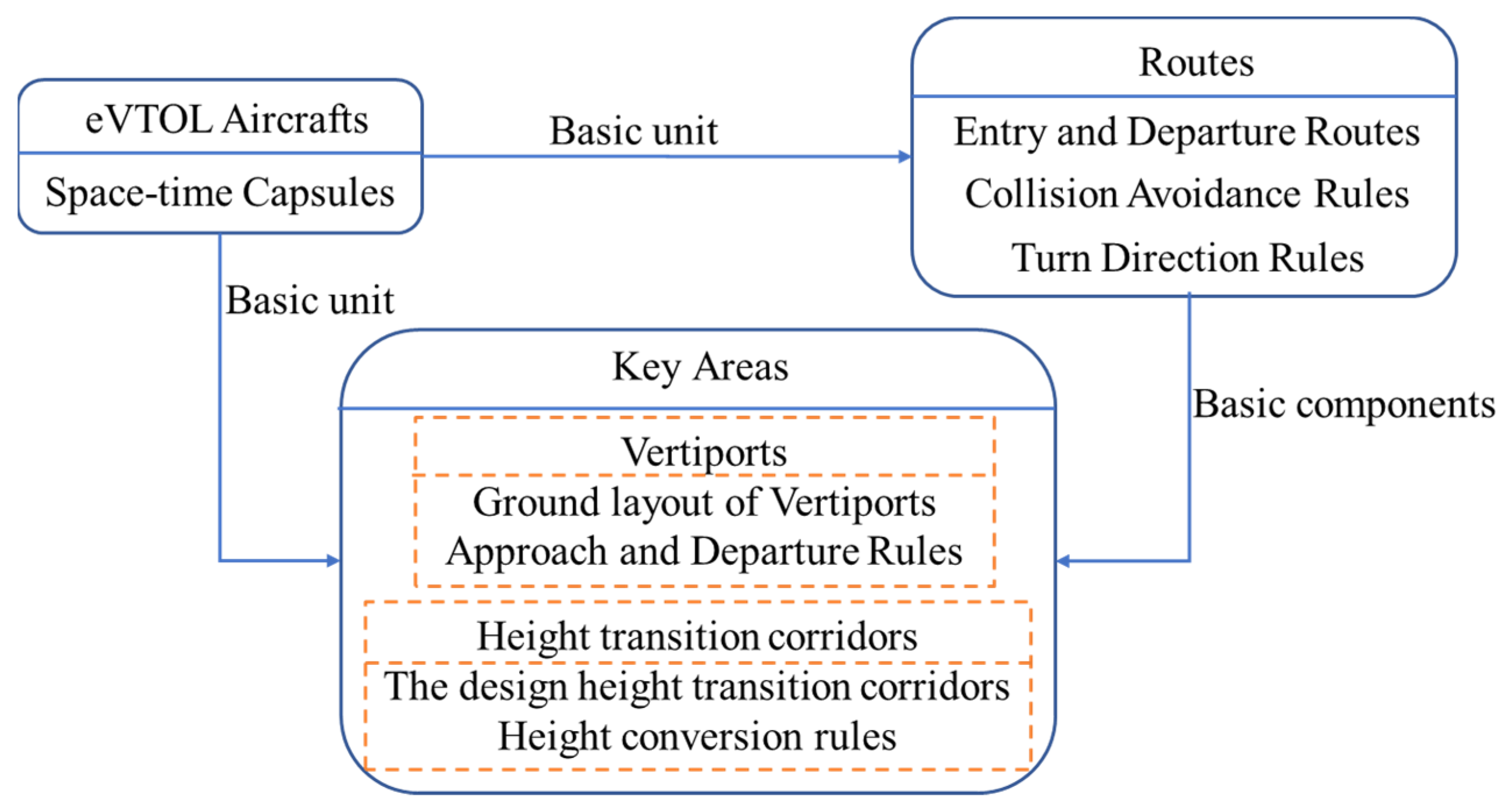
3. Urban Air Mobility Traffic Rules Framework

3.1. Assumptions

The UAM traffic rules can unify the flight behaviour of eVTOL aircraft operating on a large scale, ensure their orderly, efficient, and safe flight, and provide a prerequisite for flow control. However, the completion of these rules requires a number of conditions that cannot currently be met as necessary, and we, therefore, propose a number of assumptions regarding the UAM operating rules:
① All flights take place in urban environments, always being within controlled airspace, and they make public flight plans.
② In the urban airspace, there is a detect and avoid (DDA) system that provides services such as communication, navigation, surveillance, and avoidance with sufficient precision.
③ The rules requiring vertical climb and descent only consider whether the eVTOL aircraft can complete the manoeuvre, leaving motor efficiency out of the equation for now.
④ All eVTL aircraft take off and land on vertiports.

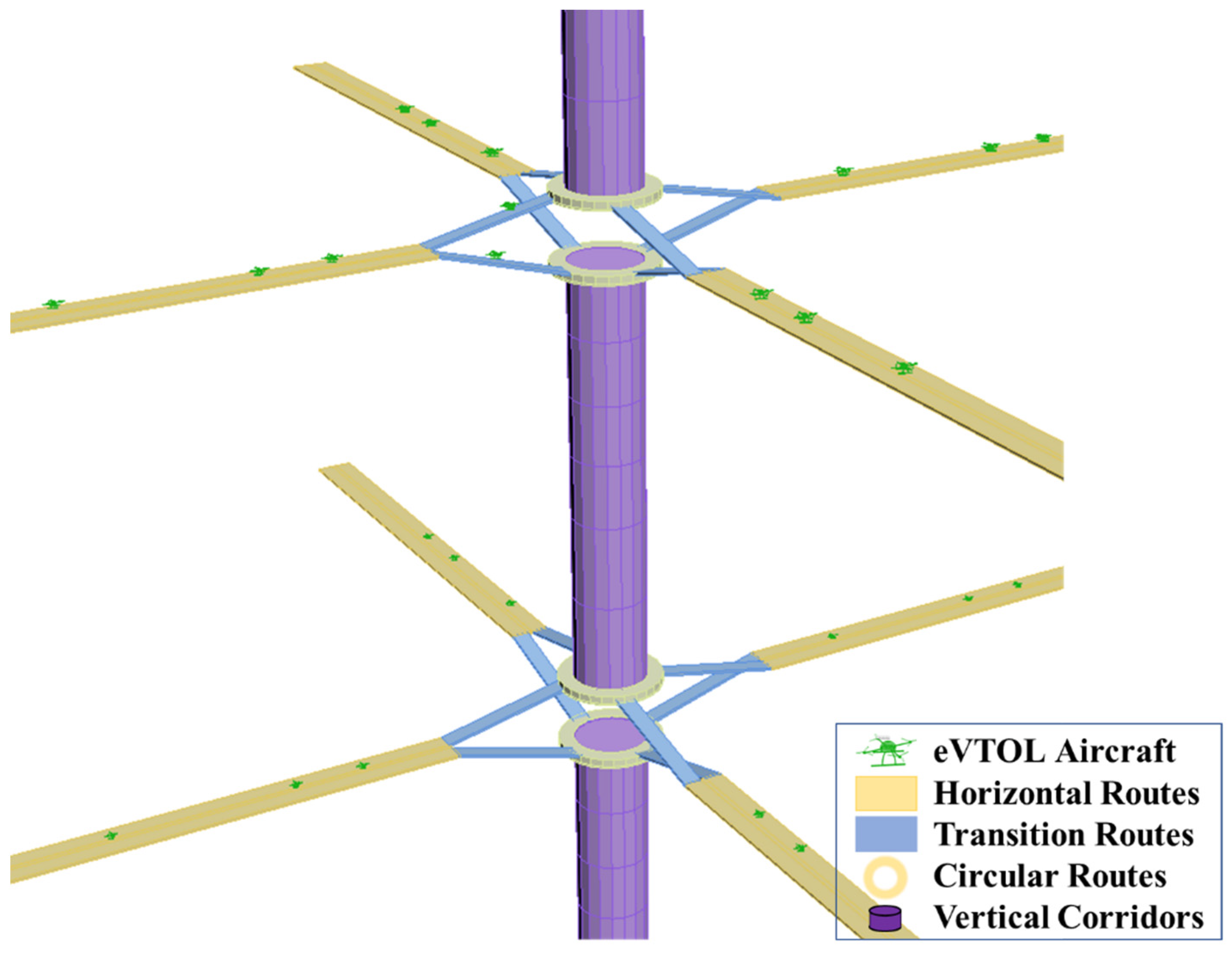
3.2. Analytical Framework

To sufficiently cater to urban transportation modes, the design of the UAM traffic rules involves the entire transportation process. We designed the traffic rules according to three main dimensions: eVTOL aircraft, key routes, and key areas, the analytical framework is shown in Figure 1.

4. Urban Air Mobility Traffic Rules

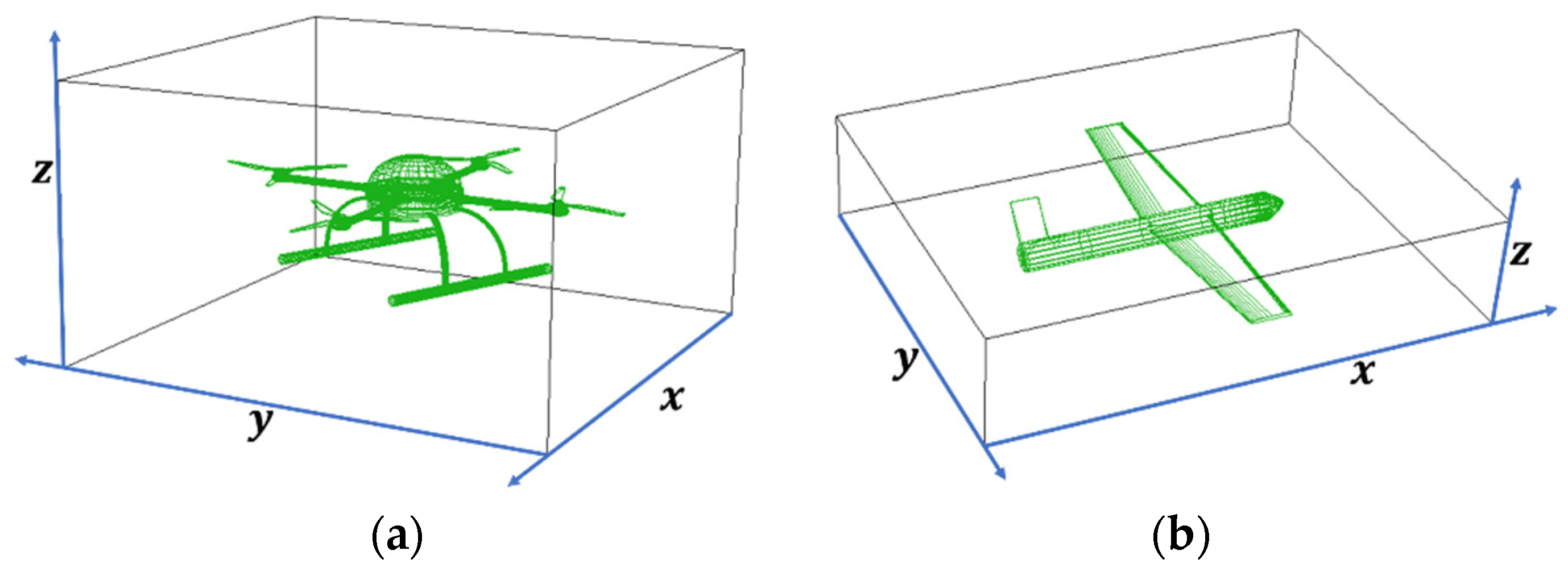
4.1. eVTOL Aircraft as “Space-Time Capsule”

To overcome the large disparity in aircraft type, safety interval, and aerodynamic characteristics between eVTOL aircraft and the difficulty of control, we propose the concept of space-time capsule. The space-time capsule can reflect the status of each eVTOL aircraft, especially when the eVTOL aircraft has degraded performance and/or malfunction, which is important for the safe operation of the flight path network. Each eVTOL aircraft is modelled as a “space-time capsule,” which serves as a basic unit for UAM to manage low-altitude airspace and perform traffic control. The space-time capsule is a virtual hood that is specifically designed to obtain the model characteristics of an eVTOL aircraft. The boundary of this virtual hood is a rectangle that consists of the largest distance of perturbations generated by the eVTOL aircraft in six directions of the Cartesian co-ordinate system. We position the eVTOL aircraft in the Cartesian co-ordinate system and use the forward direction of the eVTOL aircraft as the positive x-axis, horizontal direction as the y-axis, and the vertical direction as the z-axis, with upward and downward directions as positive and negative, respectively. The motion of the eVTOL aircraft in airspace has six degrees of freedom and, based on this, the motion states are either vertical motion, horizontal motion, pitch, roll, or yaw. We assume that the motion state of the eVTOL aircraft could be in any state in the next instant and, thus, the airflow disturbance distances resulting from all possible motion states are considered in the construction of the spatiotemporal capsule. Because the shape of the “space-time capsule” considerably affects calculation of the boundary of the “space-time capsule” under high flow control, we choose a rectangular body, which is easier to calculate. We designed the space-time capsule for two typical eVTOL aircraft, fixed-wing and multi-rotor; the schematic diagram is shown in Figure 2.

4.1.1. Safety Distance in x-Axis Positive Direction

We assume that all eVTOL aircraft may be queuing to fly on the same fixed route; there needs to be enough distance to slow down and stop when the ahead aircraft stops. The safety distance D x of a fixed-wing eVTOL aircraft in the positive x-axis direction is calculated in the same manner as that in the multi-rotor eVTOL aircraft. The safety distance D x of the “space-time capsule” in the positive direction of the x-axis involves the reaction distance S r and braking distance S b . We assume that the eVTOL aircraft can respond to each other, and a certain reaction time is required when the forward eVTOL aircraft on the route suddenly brakes or receives a communication command to start braking. The reaction time is determined based on the mechanical delay, computation, and reaction times of the over-the-horizon eVTOL aircraft pilot to perform braking. The reaction distance is calculated from the reaction time and initial speed of the eVTOL aircraft. The braking distance is determined using the thrust that is generated by the eVTOL aircraft, initial velocity of the eVTOL aircraft, and wind speed. The braking distance is calculated according to the laws of kinematics as follows:
D x = S r + S b
S r = t r · v 0
s = { a k d ( s v w , x ) 2 ,   s v w , x a + k d ( s v w , x ) 2 ,   s v w , x
where D x is the eVTOL aircraft safety distance in the positive direction of the x-axis, S r is the reaction distance, S b is the braking distance, t r is the reaction time, v 0 is the initial speed of the eVTOL aircraft, S is the distance to the eVTOL aircraft, a is the eVTOL aircraft acceleration, k d is the resistance coefficient in air fluid, v w , x is the component of the wind speed on the x-axis, and s is the eVTOL aircraft velocity along the x-axis. In the case of upwind, the full braking distance is:
S b = 1 k d l n k d a e k d v w , x t x k d a c o s k d a t x + k d a s i n k d a t x
t x = 1 k d a t a n 1 k d a v 0 a + k d v w , x 2 v 0 k d v w , x
For downwind, the distance of full braking is:
S b = 1 k d l n ( k d v w , x + k d a ) e k d a t x , 1 ( k d v w , x k d a ) e k d a t x , 1 2 k d a e k d v w , x t x , 1 1 k d l n c o s t a n 1 ( v 0 v w , x ) k d a + v w , x k d a t a n 1 ( v 0 v w , x ) k d a
t x , 1 = 1 2 k d a l n a + k d v w , x a k d v w , x
where t x is the time required for complete braking and t x , 1 is the time used when the velocity of the eVTOL aircraft is equal to the component v w , x of the wind speed on the x-axis.
When the component v w , x of the wind speed along the x axis was zero:
S b = 1 k d l n   c o s t a n 1 v 0 k d a

4.1.2. Safety Distance in x-Axis Opposite Direction

The safety distance along the x-axis in the opposite direction of a multirotor eVTOL aircraft depends on the effect of rotor rotation on the airflow, which may vary according to several factors, such as the eVTOL aircraft, rotor speed, and air density. Based on the simulation results in the literature, we inferred that the safe distance in the opposite direction of the x-axis of the eVTOL aircraft is three times the rotor radius. The safe distance in the opposite direction of the x-axis for the fixed-wing eVTOL aircraft is the wake length from the wingtip vortex, and we chose a value that is 30 times the wingspan length based on simulation results in the literature [27].
D x , m r = 3 R m r
D x , f w = 30 L f w
where D x , m r are the safety distances of the multi-rotor eVTOL aircraft in the negative x-axis direction, R m r is the radius of the multi-rotor eVTOL aircraft rotor, D x , f w is the safety distance of the fixed-wing eVTOL aircraft in the negative x-axis direction, and L f w is the wingspan length of the fixed-wing eVTOL aircraft.

4.1.3. Safety Distance of y-Axis

The horizontal safety distance of multi-rotor eVTOL aircraft is related to the turning radius   r m r of the eVTOL aircraft (Figure 3) in the initial state v 0 and the horizontal distance of airflow disturbance generated by rotor rotation. To ensure safety, we choose the larger value. The horizontal influence distance from the rotor rotation is three times the value of rotor, the turning radius r m r is greater than the minimum turning radius r m r , m i n , and the minimum turning radius is determined using the minimum radius of curvature, which is calculated as follows:
D y , m r = m a x ( 3 R m r , r m r )
r m r r m r , m i n
r m r , m i n can be calculated by the maximum overload of the eVTOL aircraft.
r m r , m i n = v m r , m i n 2 g × n m r , m a x 2 1
n m r , m a x = m g 2 F C m r , m i n + 1
where D y , m r   is the safe distance of the multi-rotor eVTOL aircraft in the y-axis, g is the gravitational acceleration, v m r , m i n is the minimum flight rate of the multi-rotor eVTOL aircraft, n m r , m a x is the maximum overload of the multi-rotor eVTOL aircraft, m is the mass of the multi-rotor eVTOL aircraft, and F C m r , m i n is the minimum centripetal force of the multi-rotor eVTOL aircraft.
For the safe distance along the Y-axis of the fixed-wing eVTOL aircraft, we choose a larger tail vortex radius and minimum turning radius, which are calculated as follows:
D y , f w = m a x ( r c , r f w , m i n )
The procedure for calculating the vortex core radius of a fixed-wing eVTOL aircraft [28] is as follows:
w x = w z v y
Γ = w x d s
y c = 1 Γ y w x d s
z c = 1 Γ z w x d s
r c 2 = 1 Γ ( | y y c | 2 + ( | z z c | 2 ) w x d s
where w x is the wingtip vortex axial vortex distribution, Γ is the loop volume of the wingtip vortex, ( y c , z c ) are the vortex core centre co-ordinates, and r c is the vortex core radius.
The minimum turning radius of a fixed-wing eVTOL aircraft is related to its maximum roll angle in the horizontal plane and is calculated as follows:
r f w , m i n = v f w 2 g t a n φ f w , m a x
where r f w , m i n is the minimum turning radius of the fixed-wing eVTOL aircraft, v f w is the speed of the fixed-wing eVTOL aircraft, and φ f w , m a x   is the maximum roll angle of the fixed-wing eVTOL aircraft.

4.1.4. Safety Distance of z-Axis

The behaviour of the safe distance of the eVTOL aircraft space-time capsule in the positive z-axis direction may either be climb, inclined descent, vertical ascent, or vertical descent. For the multi-rotor eVTOL aircraft, we consider the following factors: vertical component of the braking distance during inclined climbing, braking distance during vertical climbing, airflow disturbance distance generated by the rotor during vertical descent, and vertical component of the airflow disturbance distance that is generated by the rotor during inclined descent. In addition, the airflow disturbance distance generated by the rotor in the vertical direction is 0.5 times the rotor radius.
D z , m r = m a x ( S b , S b , 0.5 R m r , 0.5 R m r )
For the fixed-wing eVTOL aircraft, we considered the vertical component of the braking distance during inclined climbing and the vertical component of the wake length during inclined flight descent.
D z , f w = m a x ( S b , 30 L f w )
The safe distance of the eVTOL aircraft space-time capsule in the opposite direction of the z-axis may vary based on four motion states: inclined climb, inclined descent, vertical climb, and vertical descent. For the multi-rotor eVTOL aircraft, we consider the airflow disturbance length in the vertical climb, vertical component of the airflow disturbance length in the inclined climb, braking distance in the vertical descent, and vertical component of the braking distance in the inclined descent.
D z , m r = m a x ( S b , S b , 0.5 R m r , 0.5 R m r )
For a fixed-wing eVTOL aircraft, we considered the vertical component of the wake length during inclined climbing and the vertical component of the braking distance during inclined descent.
D z , f w = m a x ( S b , 30 L f w )

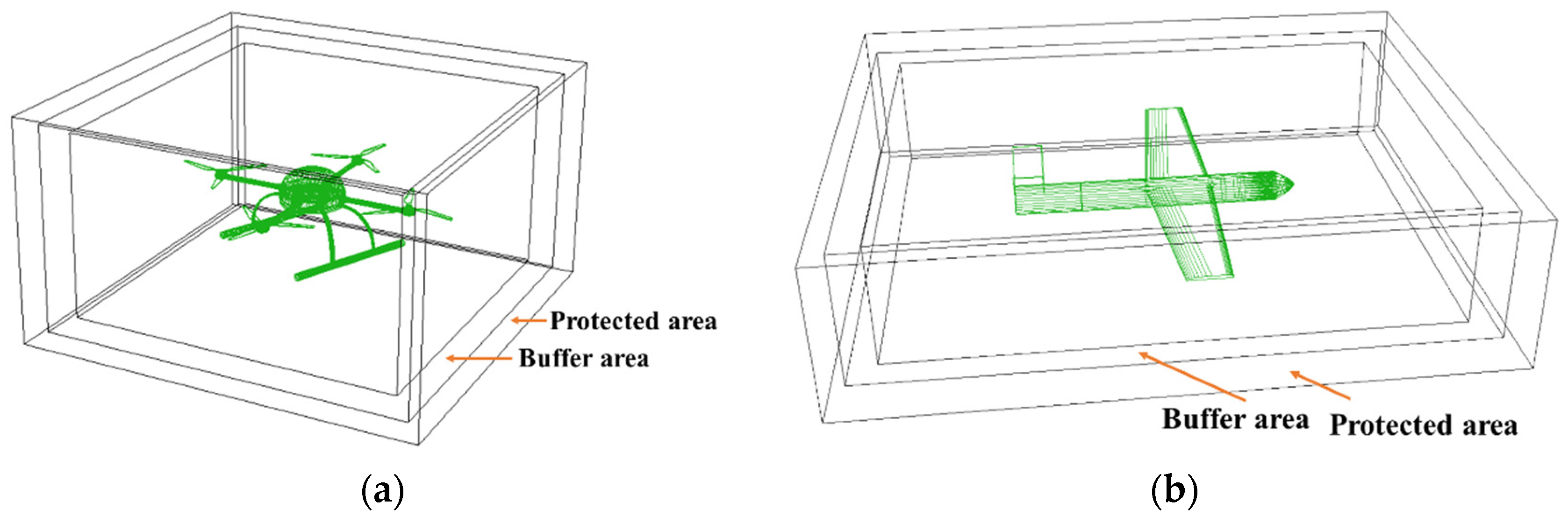
4.1.5. Design of Buffer and Protected Areas

Outside the boundaries of the space-time capsule, a protection area and a buffer area should be set to ensure safety in case of accidents as shown in Figure 4. The design of the space-time capsule for buffer and protected areas is primarily based on the positioning error of the eVTOL aircraft. However, the future communication, navigation, and surveillance equipment for the eVTOL aircraft cannot be determined and the control system has not yet been developed, so the width of the protected area and buffer zone is difficult to define.

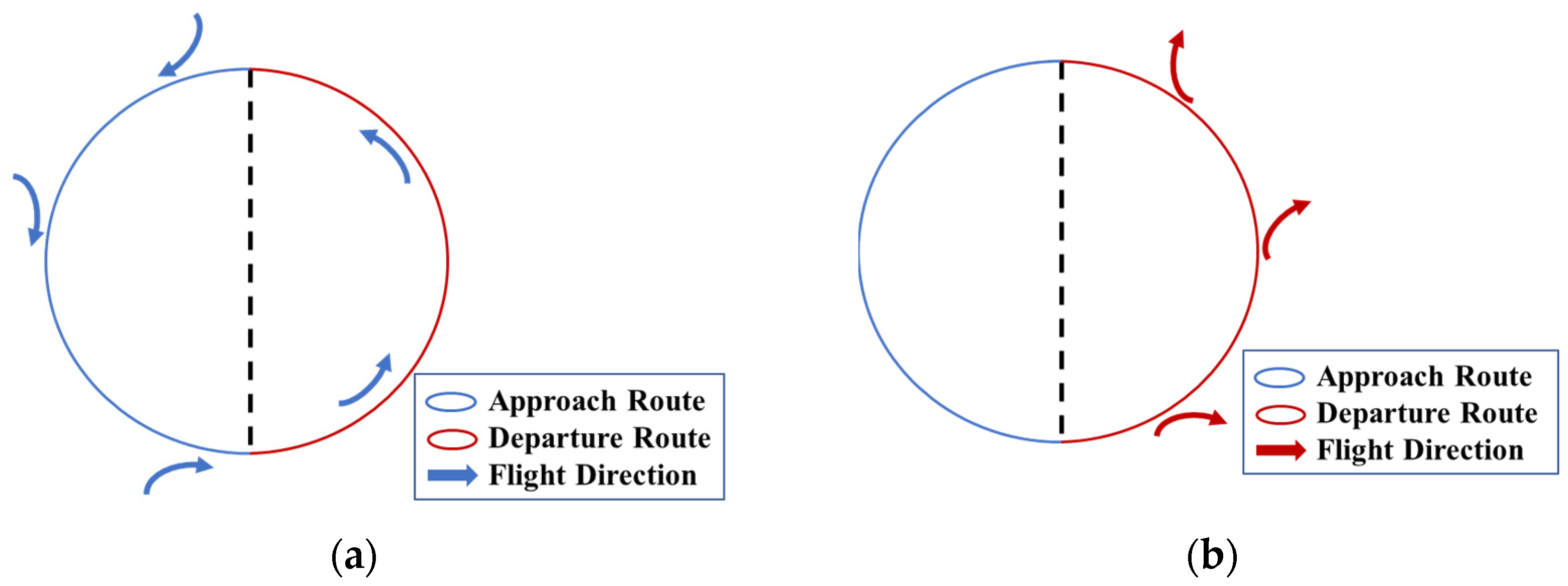
4.2. Route Traffic Rules

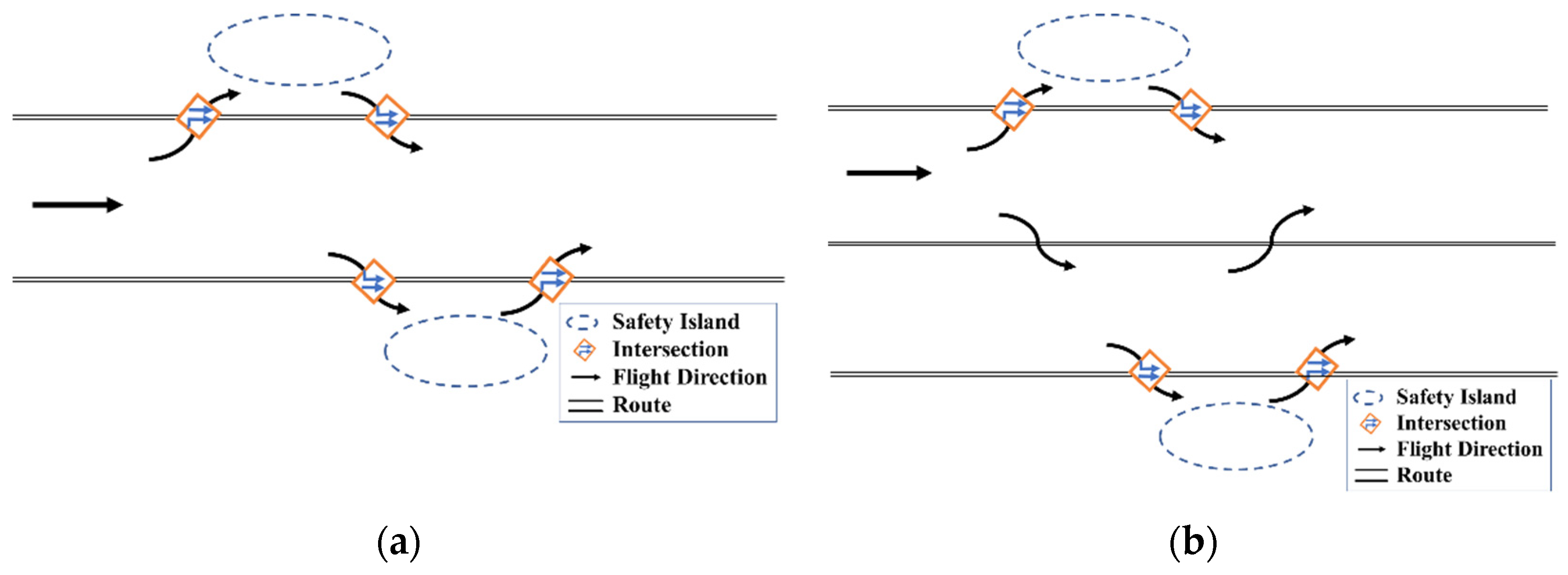
4.2.1. Entering and Leaving the Route Rules

With the UAM development, the entry and exit routes will change in phases, and the traffic rules of UAM may change accordingly. At any stage, the eVTOL aircraft must not only fly according to the rules, but also ensure that the eVTOL aircraft space-time capsule does not overlap. The rules of eVTOL aircraft route entry and departure in the early stages of UAM development are shown in Figure 5a. At this stage, the autonomous sensing, collision avoidance, and positioning technologies of eVTOL aircraft are not mature, and the route does not allow eVTOL aircraft to pass through in the parallel direction. Thus, the route is set to a single-channel mode. In addition, the eVTOL aircraft must join or leave the route through safety islands and convergence points. Safety islands and intersections are designed to control eVTOL aircraft entering and leaving the route to ensure the safe operation of the route. The eVTOL aircraft can enter or leave the safety island loop at any point but must enter or leave the route through the intersection in a clockwise direction around the loop. To control the traffic flow on the route, the intersection is equipped with adaptive “traffic lights” that set the phase of the intersection according to the predicted traffic conditions on the route. In addition, the maximum efficiency of adaptive “traffic lights” requires all eVTOL aircraft to be able to feed back their relatively accurate position information to the control system in a timely manner. The control system can calculate the time when the eVTOL aircraft arrives at the intersection according to the position information and motion state of the eVTOL aircraft and design adaptive intersection phasing based on the traffic flow at different directions of the intersection with reference to the way ground traffic designs traffic light phasing. Driven by the recent technological advances and the establishment of eVTOL-aircraft-related airworthiness certification standards in the market, the route can be split into multiple side-by-side lanes. However, it still requires the use of safety islands to enter or leave the route through an intersection, as shown in Figure 5b. These lanes are designed based on factors such as eVTOL aircraft type, mission class, and mission content. For example, ground traffic lanes are set at different widths depending on usage, the values being 3.75 m for highways and 3.5 m for urban roads in general. With the improvement of the control system, eVTOL aircraft are no longer restricted by lanes. Within the space range of the route, the eVTOL aircraft can fly and join or leave freely in the form of space-time capsules at any position, thus achieving safe operation with higher traffic volume and higher density.

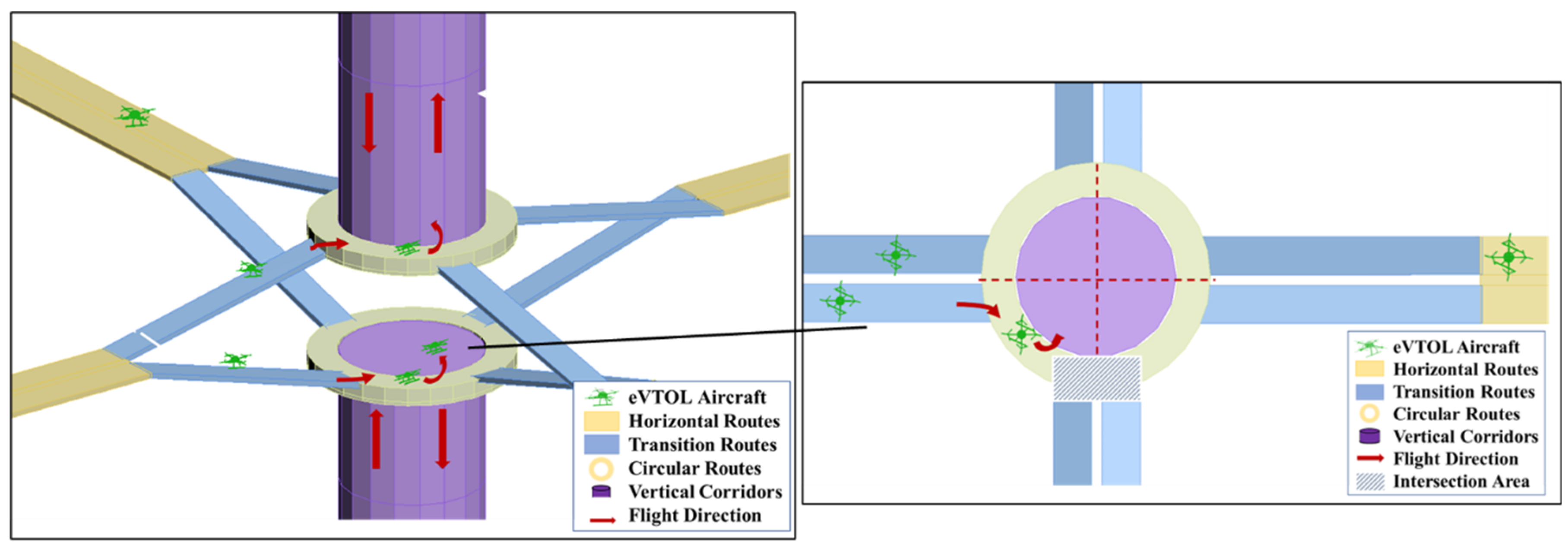
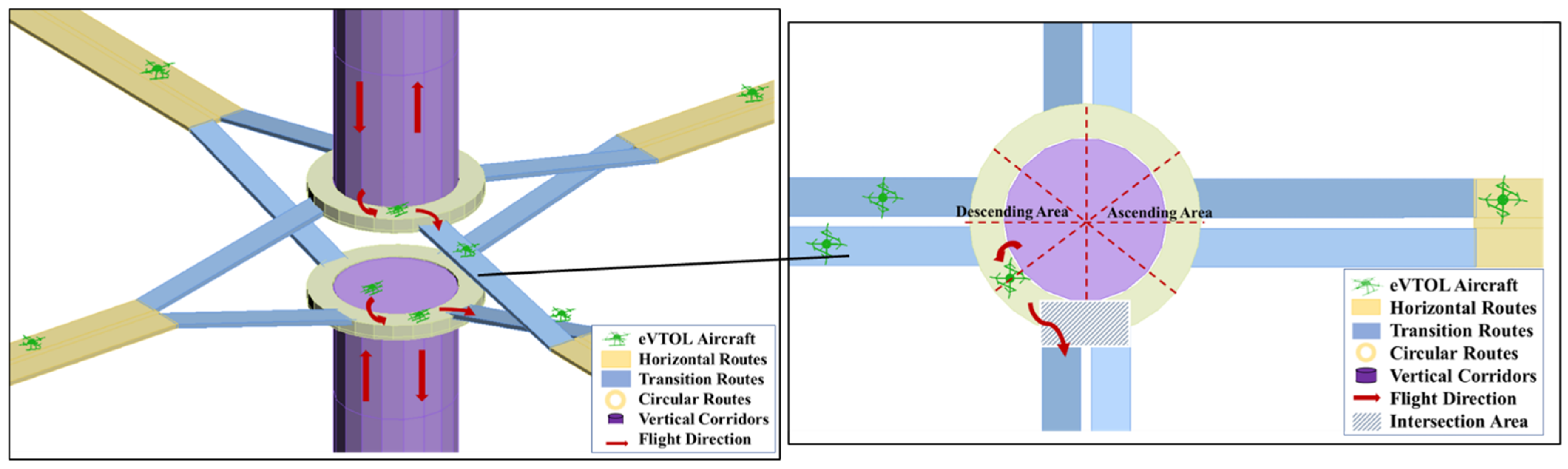
4.2.2. Collision Avoidance Rules

This section describes the collision avoidance rules under which an eVTOL aircraft may collide with another aircraft that is going straight in other directions during the straight-going process. The UAM control system can calculate the conflict status between eVTOL aircraft based on the eVTOL aircraft position, speed, route flow density, and other information. If the time capsules of the eVTOL aircraft do not overlap, they will pass directly. However, if there is an overlap, they will bypass according to collision avoidance rules. We suggest that the collision avoidance rules of eVTOL aircraft can be designed according to the mission level; emergency missions may pass straight through and the eVTOL aircraft of other mission levels circle around in the form of elliptical arcs, as shown in Figure 6a. For eVTOL aircraft of other mission levels, those with higher mission levels will circle in the upward direction and those with lower mission levels will circle in the downward direction. The eVTOL aircraft in the integrate avoidance rules based on the angle between the flight direction and the true north direction, climb at a small angle, and descend at a large angle, as shown in Figure 6b. It should be noted that the premise of the collision avoidance rules is that the eVTOL aircraft can communicate with each other or with the control system. All eVTOL aircraft are under the command of the control system and their position information must be accurate, especially the height information. The elliptical arc projected by the eVTOL aircraft on the x–z plane follows the basic equation of the ellipse, and the values of the semi-major axis a and semi-minor axis b are determined according to the route.
z = ± ( 1 x 2 a 2 ) b 2

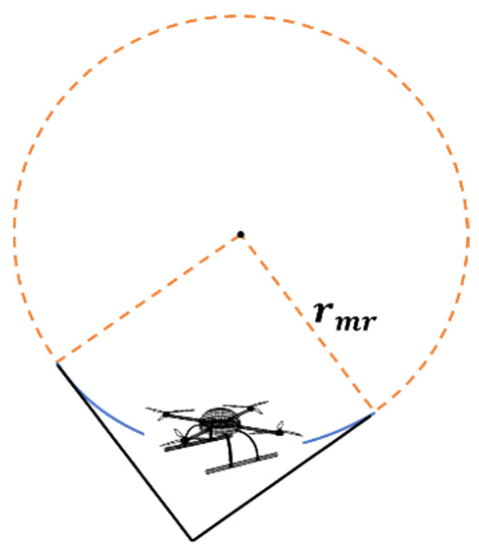
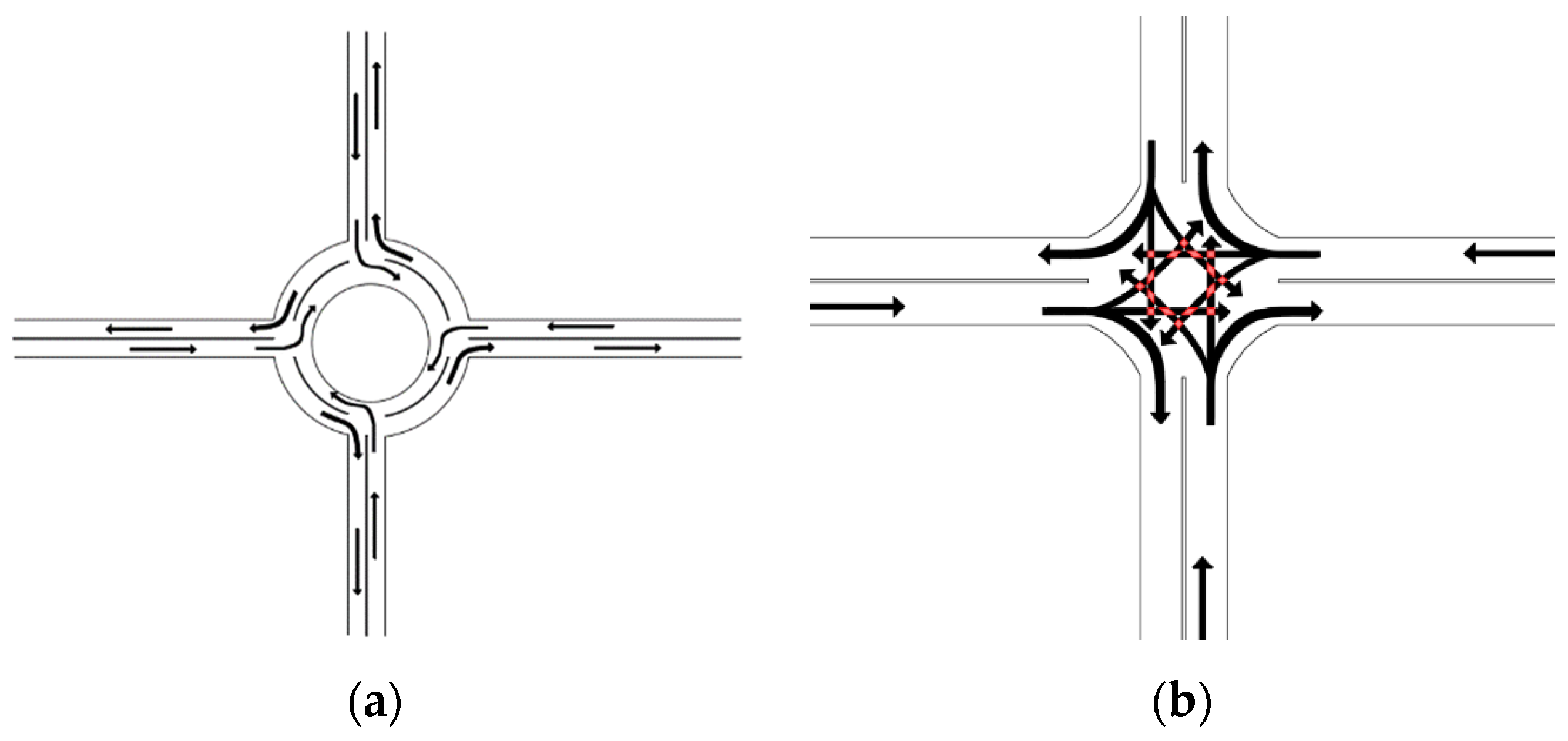
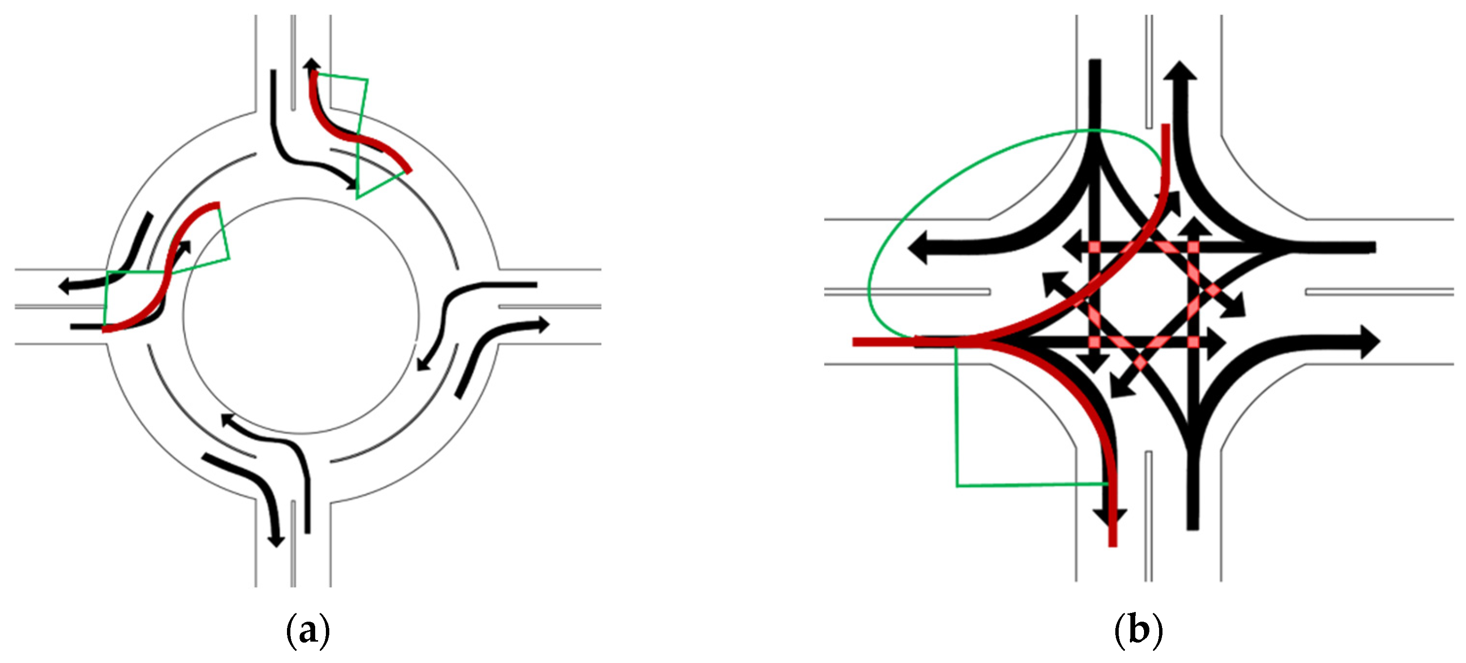
4.2.3. Turning Rules

For the traffic rules of an eVTOL aircraft changing flight direction, we propose a circular intersection and a cross intersection, shown in Figure 7. The eVTOL aircraft space-time capsule needs to be guaranteed not to overlap horizontally when flying in these two types of intersections. The roundabout intersection can avoid eVTOL aircraft conflict on the flight path and reduce the collision probability. However, the eVTOL aircraft flying around the circle may reduce the flight efficacy. Although the cross intersection can effectively improve the turning efficiency of eVTOL aircraft, the risk of collision increases dramatically when the number of eVTOL aircraft is high, and the number of conflicting routes increases.
The eVTOL aircraft enters or leaves the intersection with a circular or elliptical arc, as shown in Figure 8. The black line is the flight direction of the eVTOL aircraft, and the red line is the actual flight trajectory of the drone (arc or ellipse). The green lines are auxiliary lines to express the flight trajectory more clearly. The circular or elliptical arc projected by the eVTOL aircraft in the x–y plane follows the basic equations of a circle and an ellipse (Equation (26); Equation (27)). The values of the radius of the arc, semi-long axis of the elliptical arc, and the semi-short axis are determined according to the layout of the intersection. We prefer to choose a circular flight path because it is easier to achieve in terms of performance for existing eVTOL aircraft.
( x a ) 2 + ( y b ) 2 = r 2
x 2 a 2 + y 2 b 2 = 1

4.2.4. Altitude Transition Rules

The current management and control system is not capable enough to ensure the large-scale safe operation of eVTOL aircraft. Therefore, routes are structural and fixed like urban roads, and the flight of eVTOL aircraft is unified and orderly, rather than point-to-point. When the eVTOL aircraft changes altitude, in order to increase the orderliness of the eVTOL aircraft and reduce the pressure on the control system, we propose an altitude transition corridor, as shown in Figure 9. However, the altitude transition corridor may reduce the eVTOL aircraft flight efficiency, require higher endurance, and feed back accurate position information.
The eVTOL aircraft flying in the altitude transition corridor need to ensure that the eVTOL aircraft space-time capsule does not overlap both horizontally and vertically. The altitude transition corridor is divided into two layers to separate the ascending and descending eVTOL aircraft and subsequently avoid safety hazards. Before entering the corridor, the eVTOL aircraft climbs or descends beforehand through the blue transition routes between the horizontal routes and vertical corridors according to the flight plan, and it then enters the circular routes counter-clockwise in the form of a circular arc or elliptical arc. The yellow circular route is divided into two layers. The heightened eVTOL aircraft ramps up to the upper circular routes, and the descending eVTOL aircraft banked down to the lower circular routes. After entering the circular route, the eVTOL aircraft must enter the vertical corridor before reaching the next intersection area, and then climb or descend in the vertical corridor according to the altitude change, as shown in Figure 10.
The eVTOL aircraft leaving the altitude transition corridor must climb or descend through the vertical corridor, then keep a circular route altitude and enter a circular route counter-clockwise in the form of a circular arc. After arriving at the next intersection area, they enter the transition route with a circular or elliptical arc. In addition, we spatially separate the ascending and descending eVTOLs in the vertical corridor to better improve safety. The whole process is shown in Figure 11.

4.3. Vertiport Design

The UAM requires a vertiport for eVTOL aircraft take-off and landing. Because the existing vertiport rules are complicated, they cannot maximise the flexibility of eVTOL aircraft, resulting in low efficiency of the vertical landing field and high collision risk. In addition, the number of vertiports in the city is high, and we suggest prioritising a simpler structure layout design, smaller footprint, and investment cost. Based on these principles, we designed the vertiport based on the terminal area waiting and approach rules, vertiport ground layout, vertipods, and parking points.

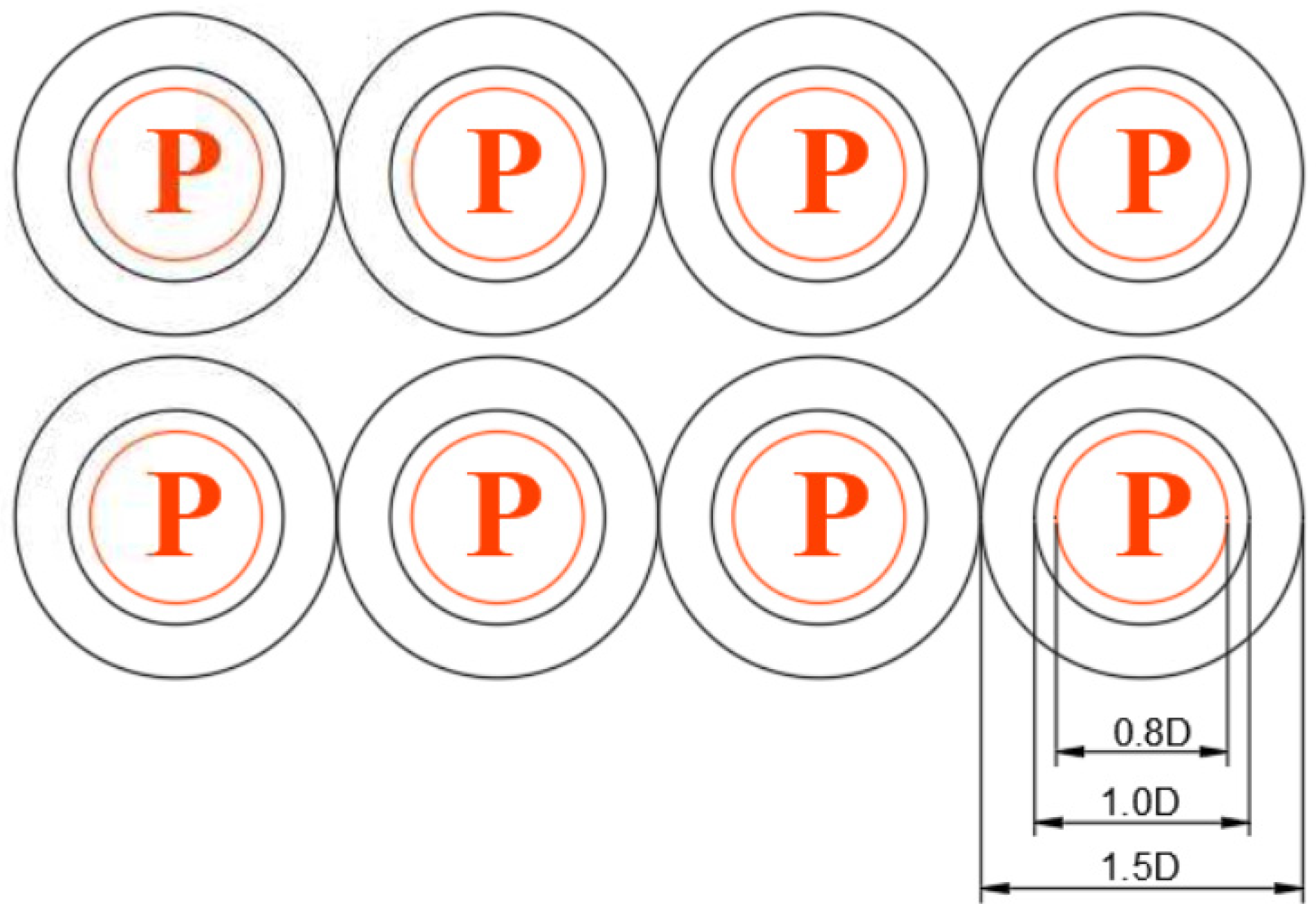
4.3.1. Vertipod and Parking Point Design

The vertiport structure is simple; it contains a vertipod for eVTOL aircraft take-off and landing and a parking point for vehicle storage. A multiloop structure is chosen to design the vertipod, and this structure is divided into approach and departure positioning loops, parking loops, and protection loops. The maximum length of the eVTOL aircraft is assumed to be D. The diameter of the approach and departure positioning ring is 0.8 D, the diameter of the parking ring is 1.2 D, and the diameter of the protection ring is 2D, as shown in Figure 12.
For the parking point, this study adopted a multi-ring design, where the diameter of the approach and departure positioning ring was 0.8 D and the diameter of the stop ring was 1.5 D as shown in Figure 13. For a compact design, no protection ring is employed, which further reduces the risks associated with take-off and landing.

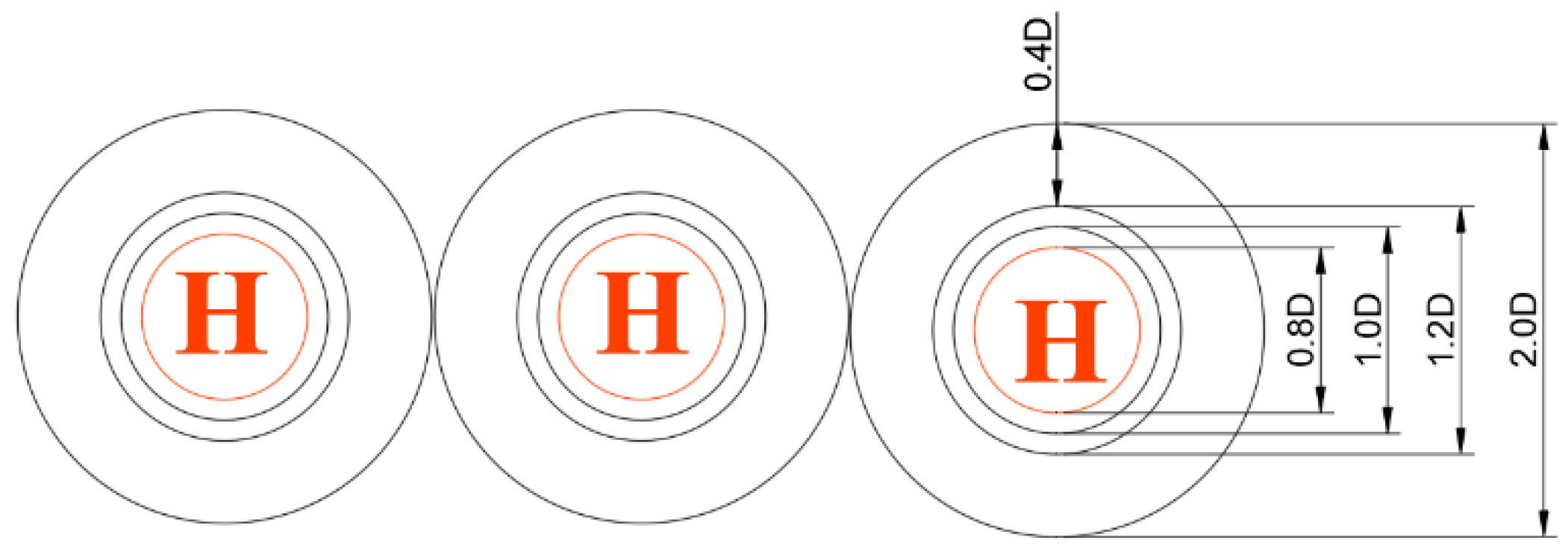
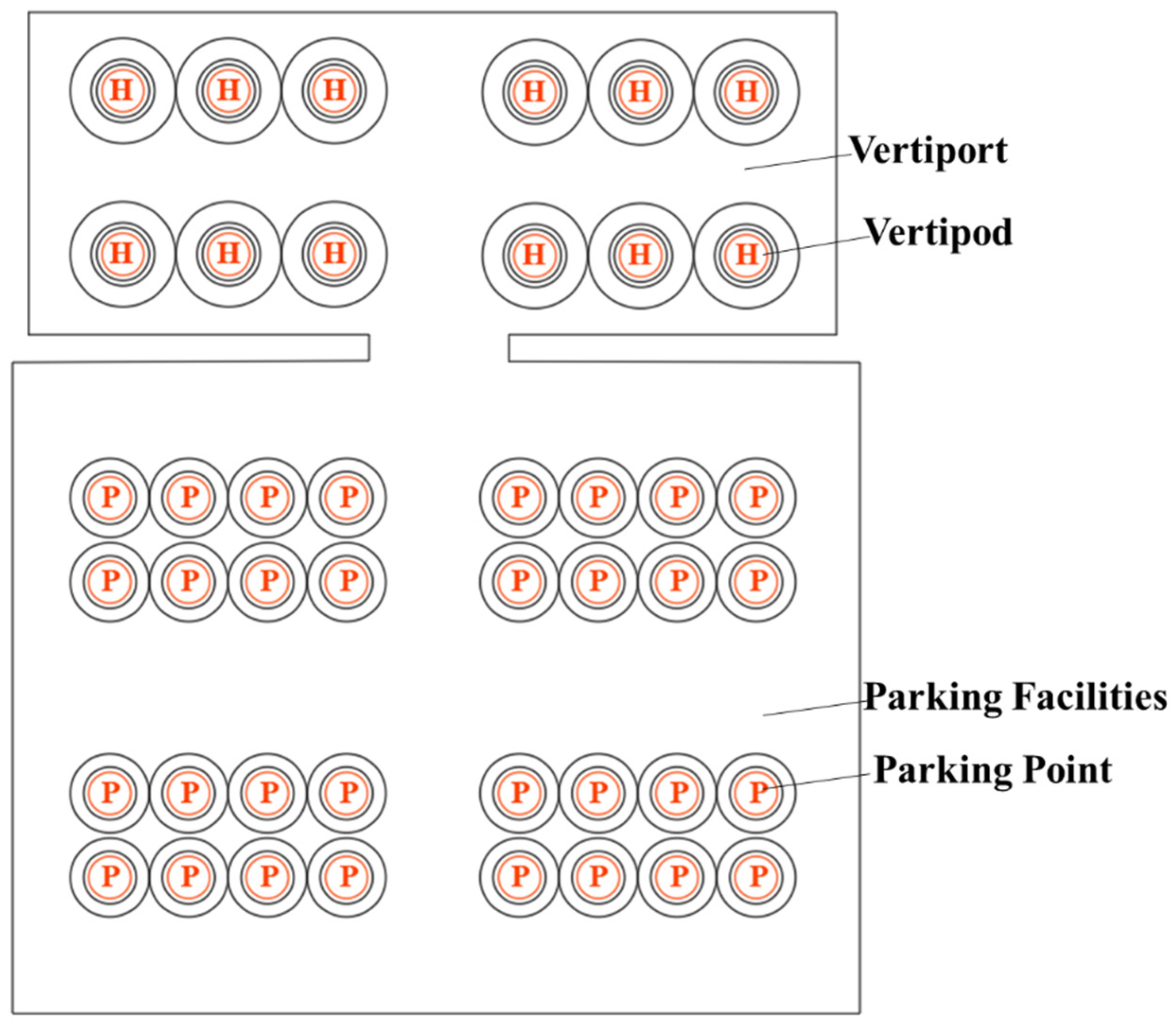
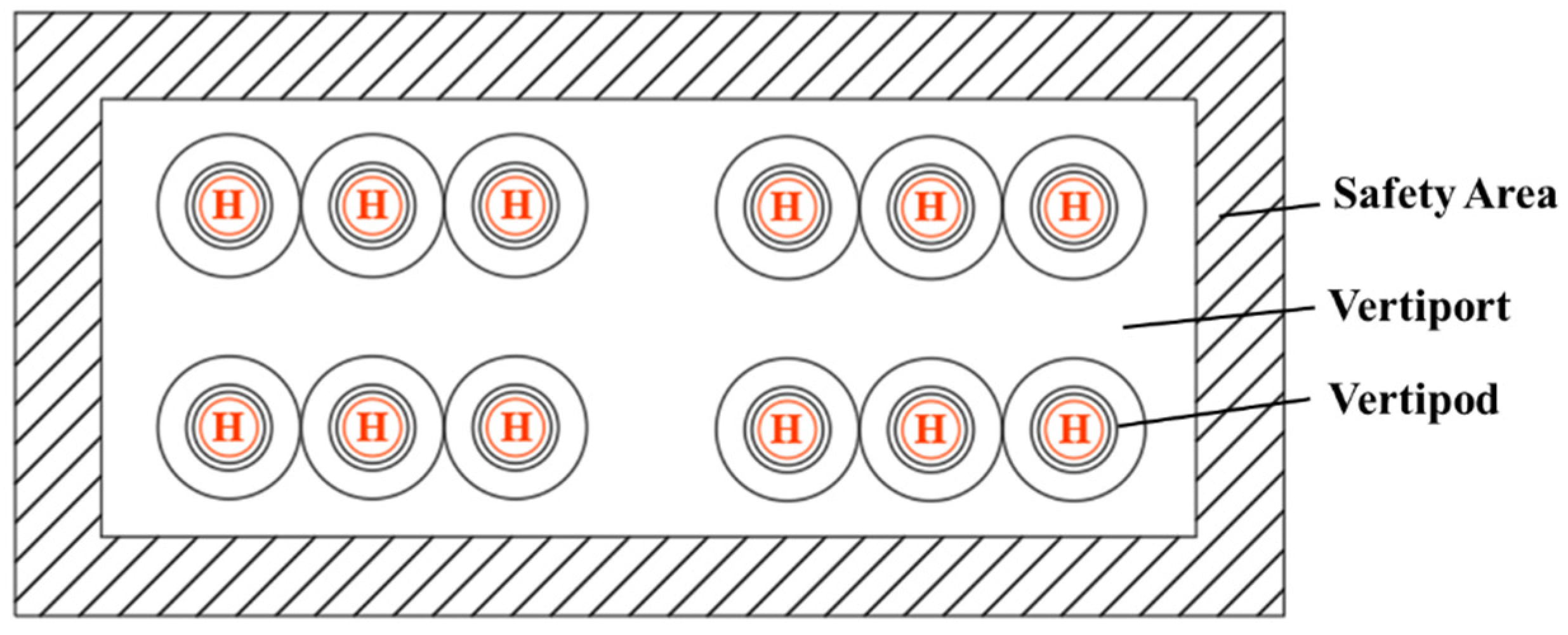
4.3.2. Vertiport Ground Layout

A vertiport can be located on the roof of a building, open space on the ground, or on a transportation hub. The vertiport at different locations may be affected by various factors, such as the occupiable area, low-altitude airspace environment, and vertiport level. To address this issue, we propose two vertiport layout methods.
The vertiport is located on the open ground and traffic hub, as shown in Figure 14. Such a vertiport can be coupled with ground transportation modes to realise multimodal transportation. Moreover, there may be a need to store eVTOL aircraft and, thus, it is necessary to consider designing parking points for eVTOL aircraft accordingly. The eVTOL aircraft possess vertical take-off and landing capabilities, and they only require a vertipod to complete take-off and landing; as a result, a specific design is not required. In addition, the number of eVTOL aircraft passengers is small, and we suggest that the vertiport need not design a dedicated gate. The gates can be used for passenger boarding, take-off, and landing. Not designing the gate does not have an adverse impact on the efficiency of eVTOL aircraft take-off and landing and, thus, the flexibility of the eVTOL aircraft can be fully utilised, which may help avoid the possible risks during taxiing.
A vertical vertiport is located on the building roof, as shown in Figure 15. Such a vertiport can occupy a limited area; only an eVTOL aircraft can provide take-off and landing services and, thus, only a certain width of protected area around the vertiport and vertipod needs to be designed.

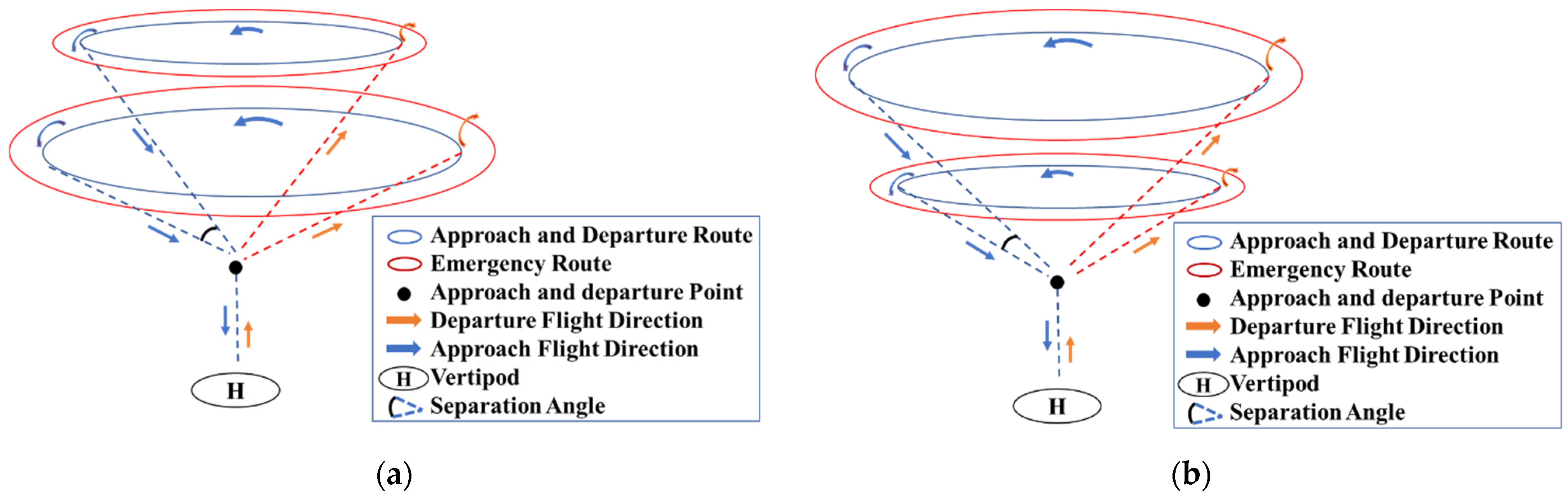
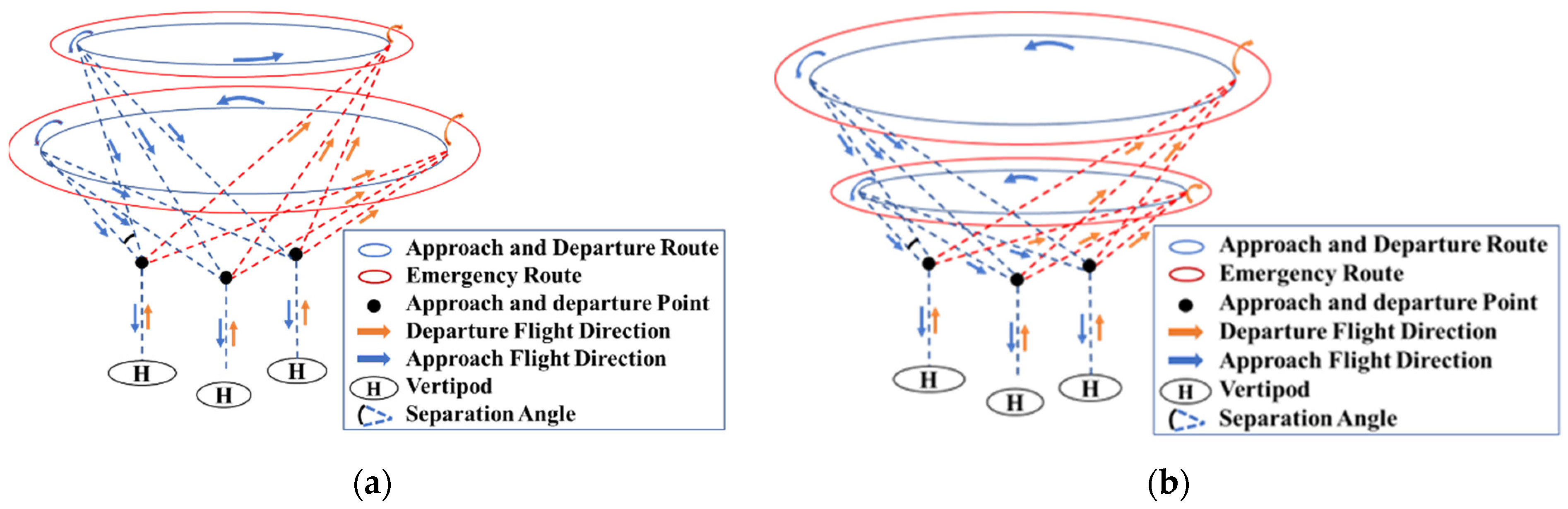
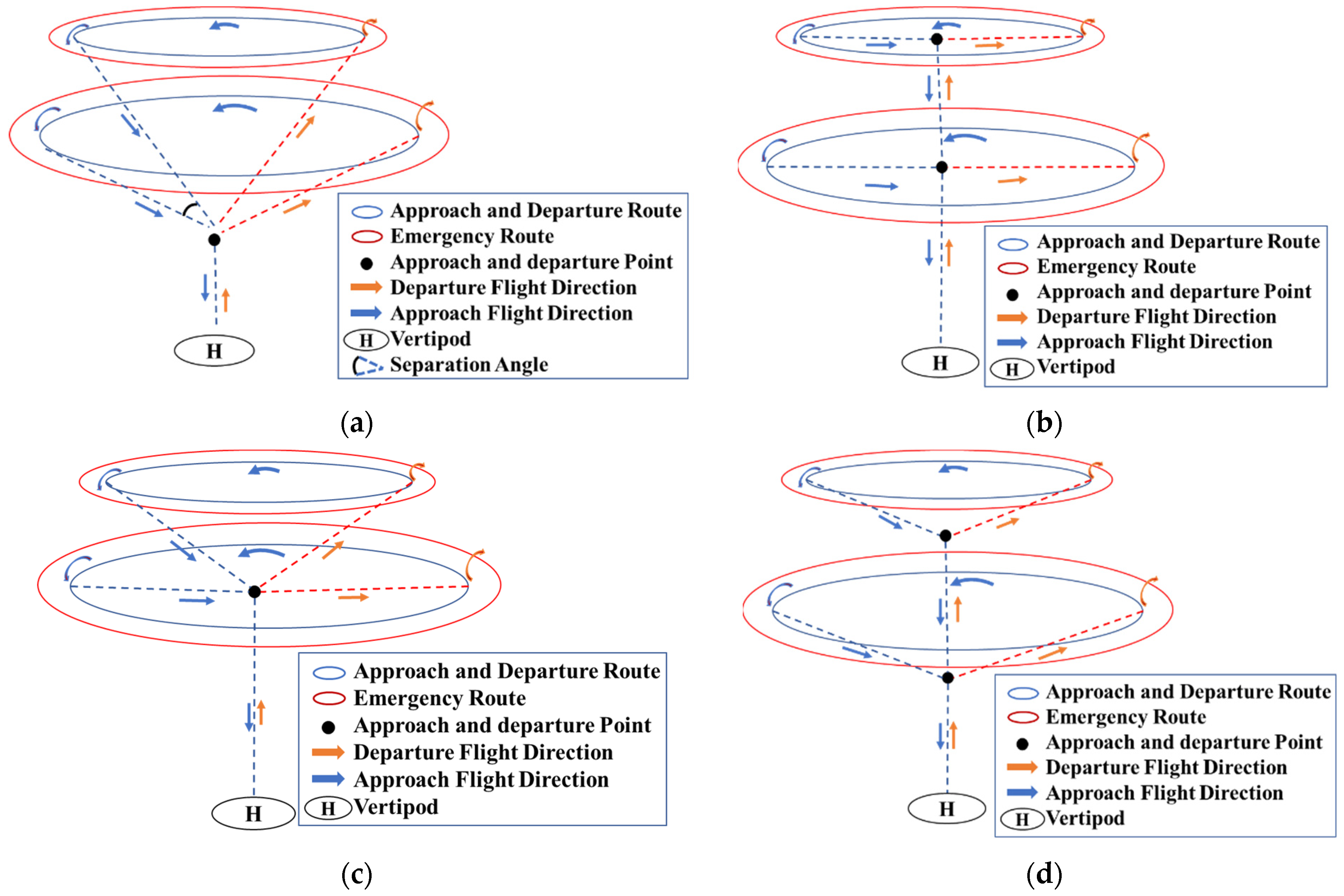
4.3.3. Terminal Area Approach and Departure Rules

  • Terminal Area Route
For routes in the terminal area, we propose a combination of the waiting and approach–departure routes in the terminal area to improve approach–departure efficiency. Due to the heavy traffic carried by vertiports, the rules in the terminal area are different from those for helicopters. Moreover, our proposed rules for terminal areas differ from those proposed by the FAA and EASA, and we prefer simpler rules [29,30]. The eVTOL aircraft flying in the terminal area need to ensure that the eVTOL aircraft space-time capsule does not overlap both horizontally and vertically. The waiting and approach–departure routes consist of several circles with different diameters and heights, and we propose two possible layouts shown in Figure 16. A primary difference between these two layouts is the separation angle between the routes. In the approach and departure process of high traffic density, the larger the separation angle in the same space, the better it is to ensure the operational safety of the terminal area, particularly in the vertical take-off and landing field containing multiple vertical take-off and landing points, as shown in Figure 17. The advantages and disadvantages of the two layouts in terms of operational efficiency, operational risk, and feasibility must be further quantified and analysed. We designed concentric circles at the periphery of the approach and departure routes as emergency routes to ensure that the eVTOL aircraft prioritise landing in case of emergency missions or malfunctions, as shown in the red part of Figure 16. An emergency route located outside the approach and departure route ensures that the eVTOL aircraft is relatively less disturbed by other eVTOL aircraft and completes the approach process as soon as possible.
2.
Layout of Approaching and Departure Positioning Points in the Terminal Area
The number and location of the approach and departure positioning points are also important parts of the terminal area rules and, thus, we propose four possible forms shown in Figure 18. A comparison of Figure 18a with Figure 18c and Figure 18b with Figure 18d helps analyse the impact of the location of the approach and departure positioning points on the UAM control system in the terminal area. A comparison of Figure 18a with Figure 18d summarises the impact of the number of approach and departure positioning points on the UAM control system in the terminal area.
3.
Operating Rule for Approach and Departure Route
Each circle of approach and departure consists of an approach and departure route, respectively. The departure route is a clockwise rotation of 0–180° in the xy plane in the north direction, and the approach route is a clockwise rotation of 180–360° in the xy plane in the due north direction, as shown in Figure 19. In this approach, the eVTOL aircraft can fly only to the approach–departure positioning point within the approach route range. If the aircraft cannot finish within this range, it must continue to fly around the circle until it enters the approach course range again, whereas the departure course need not consider this problem.

5. Simulation

The validation site of this experiment was in Jiujiang, Jiangxi Province, as shown in Figure 20. DJI M300 RTK and JOUAV CW-15 were used to verify the rationality of the traffic rule design, as shown in Figure 21.

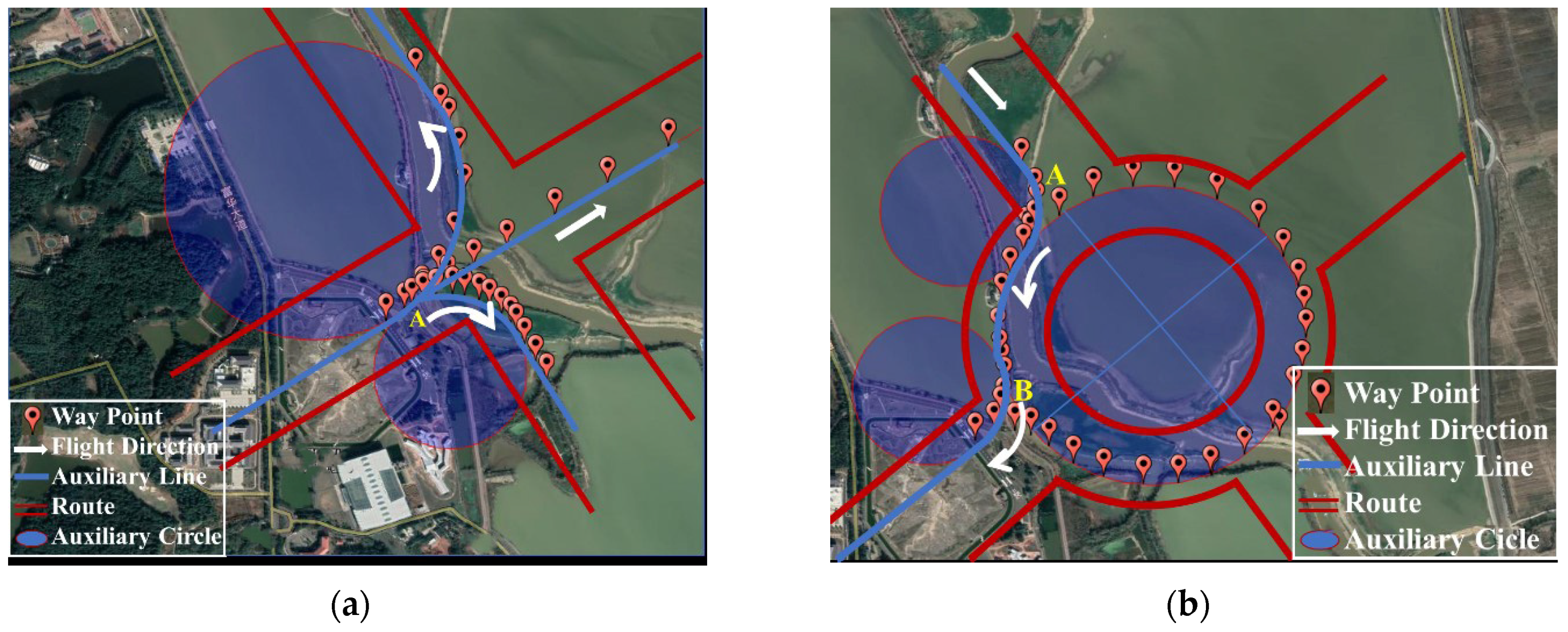
5.1. Simulation of Entering and Leaving Route Rules

We simulated the rules for entering and leaving the route, as shown in Figure 22. Figure 22a shows the simulation trajectory diagram of an eVTOL aircraft leaving the route. If an eVTOL aircraft intends to leave the route in the course of flight, it may do so through point A in the form of a circular arc and cut into a safety island at point B to complete the process. Figure 22b shows the simulation trajectory of the eVTOL aircraft entering the route. If the eVTOL aircraft intends to enter the route in the course of flight, it may leave the safety island through point B in the form of a circular arc and cut into the route at point C to complete the process.

5.2. Simulation of Collision Avoidance Rules

We simulated the collision-avoidance rule; Figure 23 shows the simulated trajectory.
We set the cruise altitude of the eVTOL aircraft to 200 m, climbed 30 m, and then descended to the cruise altitude to complete the collision avoidance rule. Figure 24 shows the altitude profiles of the different waypoints during the flight.

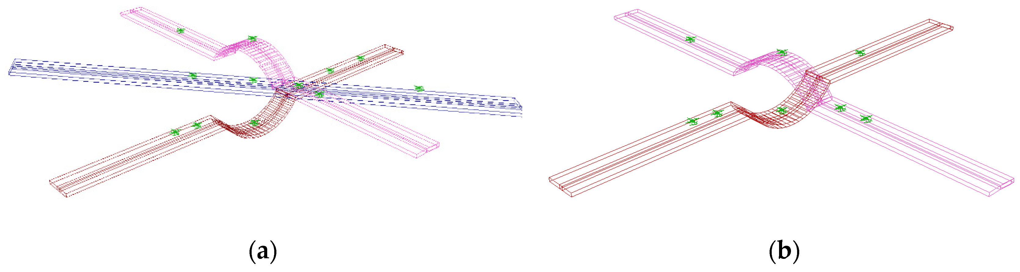
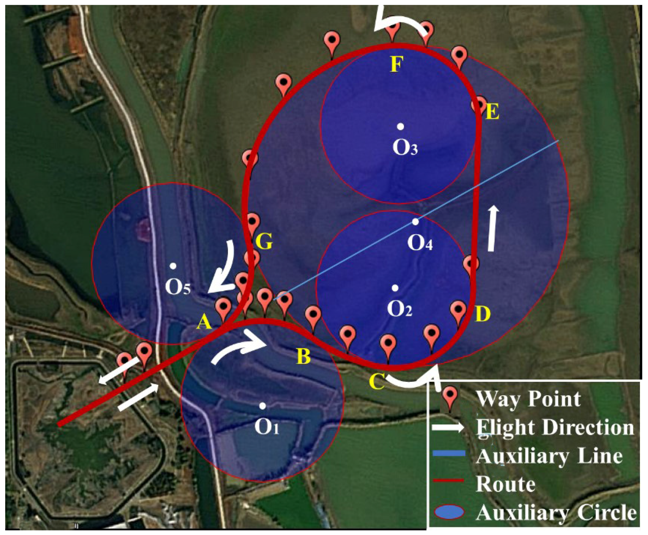
5.3. Simulation of Turning Rules

We simulated the turning rule, as shown in Figure 25. Figure 25a shows the simulation verification of the cross intersection. The eVTOL aircraft enters the intersection and selects the direction in which the aircraft should turn at point A to turn in a circular arc form. Figure 25b shows a roundabout intersection. The eVTOL aircraft enters the intersection and circles counter-clockwise at point A and exits at point B.

5.4. Simulation of Altitude Transition Rules

We simulated the altitude transition rule, as shown in Figure 26. The inclined climb before the eVTOL aircraft enters point A simulates the flight of the eVTOL aircraft in the transition routes before entering the altitude transition corridor. Circular arc AB and circular arc BC simulate the eVTOL aircraft from the transition routes to the circular routes. Arc CD simulates the eVTOL aircraft from the circular routes to the vertical corridor. Arc EF simulates the eVTOL aircraft exiting the altitude transition corridor and moving from the vertical corridor to the circular routes. Circular arc FG is the eVTOL aircraft flying in the circular routes. Circular arc GA is the eVTOL aircraft flying from the circular routes to the transition routes, after exiting point A, to complete the simulation. The eVTOL aircraft enters the altitude transition corridor from point A, travels around circle O1 to point B, and then flies around circle O4 to point C. It starts to hover around circle O2 for altitude descent and must descend to a specified altitude before reaching point D. We set the altitude before the descent to 200 m and that after the descent to 180 m. After reaching the specified altitude, the eVTOL aircraft flies from point D to point E, and then flies around circle O3 to point F to prepare to exit the altitude transition corridor. The eVTOL aircraft flies around circle O4 from point F to point G, and then flies around O5 from point G to point A to exit the altitude transition corridor.

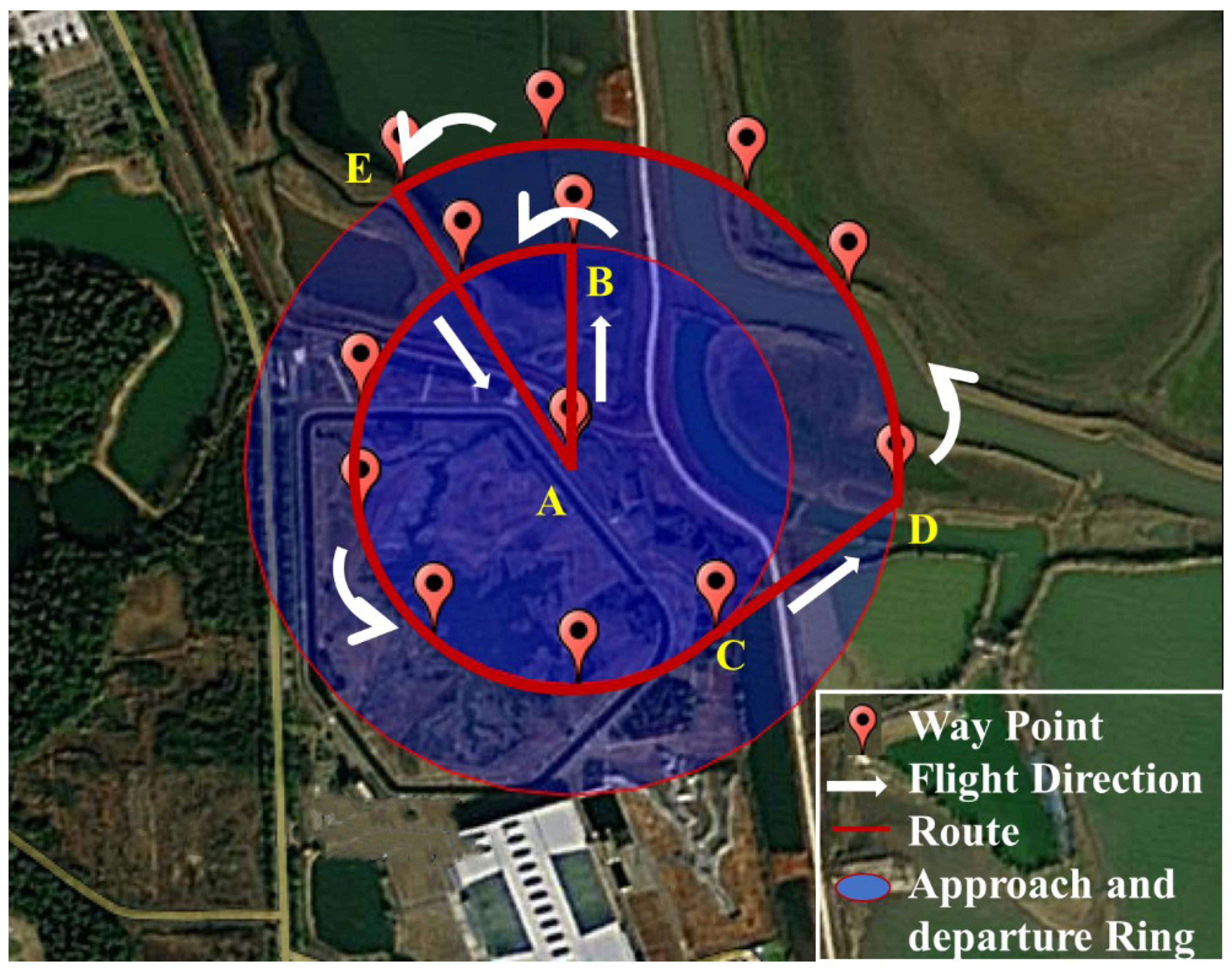
5.5. Simulation of Terminal Area Approach and Departure Rules

We simulated the terminal area approach and departure rule, as shown in Figure 27. The eVTOL aircraft climbs vertically from point A to the approach positioning point, and then inclines to point B, circles counter-clockwise around the approach and departure route to point C, then inclines to point D, circles counter-clockwise to point E, and then incline descends to the take-off approach positioning point. It finally lands vertically to point A.

6. Conclusions and Research Limitations

6.1. Conclusions

This article proposes several alternative UAM traffic rules from the perspective of a single eVTOL aircraft, certain route, and a key control area, and we validate the traffic rules using a real eVTOL aircraft to simulate them. The results showed that the performance of the existing eVTOL aircraft could fully accomplish the actions specified by these traffic rules and the design of traffic rules is reasonable. By modelling each eVTOL aircraft as a space-time capsule, eVTOL aircraft with large differences can be transformed into cuboids, thereby effectively reducing the computational pressure of the control system for separating eVTOL aircraft in large-scale operations. In terms of route rule design, the entry and departure route rules, altitude conversion rules, turn-around rules, and collision avoidance rules can effectively reduce the risk of collision from space by unifying the flight behaviour of eVTOL aircraft, and also provide reference for the government to design UAM rules. For the terminal area, we propose simpler approach and departure rules, which may amplify the performance advantages of eVTOL and maximise approach and departure efficiency. However, the UAM traffic rules are effective only if the communication, navigation, and surveillance devices can provide accurate information about the eVTOL aircraft, which may determine the density of traffic flow in the UAM. Furthermore, our proposed traffic rules may not be the most efficient or safe ones, and we will analyse this in future studies to assess the advantages and disadvantages of various traffic rules.

6.2. Research Limitations

The traffic rules we design based on the proposed assumptions are somewhat idealistic. On the one hand, a sufficiently accurate DAA system determines whether UAM can achieve safe operation and, thus, determines whether UAM can truly achieve large-scale operation. On the other hand, although these traffic rules can be completed in action, they still pose challenges to the existing eVTOL aircraft in terms of efficiency. Finally, the convergence of UTM, ATM, and UAM operations and control is one of the areas of research that needs to be explored in the future. Questions such as how to share flight plans for all types of aircraft, which system will unify these flight plans or develop a new one, and what type of aircraft will have a higher priority are difficult to deal with.

Author Contributions

Conceptualization, W.Q., X.L.; methodology, W.Q., A.T.; software, W.Q., H.H.; validation, W.Q., X.T.; formal analysis, W.Q.; resources, X.L., X.T.; writing—original draft preparation, W.Q., C.X.; writing—review and editing, W.Q., C.X.; visualization, W.Q.; funding acquisition, X.L. All authors have read and agreed to the published version of the manuscript.”

Funding

This research was funded by the National Natural Science Foundation of China grant number 41971359.

Conflicts of Interest

The authors declare no conflict of interest.

References

  1. Schweiger, K.; Preis, L. Urban Air Mobility: Systematic Review of Scientific Publications and Regulations for Vertiport Design and Operations. Drones 2022, 6, 179. [Google Scholar] [CrossRef]
  2. Piancastelli, L.; Sali, M.; Leon-Cardenas, C. Basic Considerations and Conceptual Design of a VSTOL Vehicle for Urban Transportation. Drones 2022, 6, 102. [Google Scholar] [CrossRef]
  3. Sherman, J. eVTOLS—What are they? Presentation for: An Introduction to Urban Air Mobility for State and Local Decision Makers: A Virtual Workshop Sponsored by the Community Air Mobility Initiative (CAMI). Available online: https://www.communityairmobility.org/uam101 (accessed on 4 May 2021).
  4. Thipphavong, D.P.; Apaza, R.; Barmore, B.; Battiste, V.; Burian, B.; Dao, Q.; Feary, M.; Go, S.; Goodrich, K.H.; Homola, J.; et al. Urban Air Mobility Airspace Integration Concepts and Considerations. In Proceedings of the 2018 Aviation Technology, Integration, and Operations Conference, Atlanta, GA, USA, 25–29 June 2018. [Google Scholar]
  5. Holden, J.; Goel, N. Fast-Forwarding to a Future of On-Demand Urban Air Transportation; Elevate: San Francisco, CA, USA, 2016. [Google Scholar]
  6. Collins, C.A.; Roberson, G.T.; Hale, S.A. FAA 14 CFR Part 107 for Commercial UAS and UAS as Agriculture Field Equipment: A Review for Agriculture Safety Standards; American Society of Agricultural and Biological Engineers: St. Joseph, MI, USA, 2018. [Google Scholar]
  7. Kopardekar, P.; Rios, J.; Prevot, T.; Johnson, M.; Jung, J.; Robinson, J.E. Unmanned Aircraft System Traffic Management (UTM) Concept of Operations. In Proceedings of the American Institute of Aeronautics and Astronautics, Washington, DC, USA, 13 June 2016. [Google Scholar]
  8. SESAR. U-Space Blueprint; European Union: Brussels, Belgium, 2017. [Google Scholar]
  9. Çetin, E.; Cano, A.; Deransy, R.; Tres, S.; Barrado, C. Implementing Mitigations for Improving Societal Acceptance of Urban Air Mobility. Drones 2022, 6, 28. [Google Scholar] [CrossRef]
  10. EASA. Easy Access Rules for Standardised European Rules of the Air (SERA); European Union: Brussels, Belgium, March 2022.
  11. Xu, C.; Liao, X.; Ye, H.; Yue, H. Iterative construction of low-altitude UAV air route network in urban areas: Case planning and assessment. J. Geogr. Sci. 2020, 30, 1534–1552. [Google Scholar] [CrossRef]
  12. Pathiyil, L.; Low, K.H.; Soon, B.H.; Mao, S. Enabling Safe Operations of Unmanned Aircraft Systems in an Urban Environment: A Preliminary Study. In The International Symposium on Enhanced Solutions for Aircraft and Vehicle Surveillance Applications (ESAVS 2016); German Institute of Navigation and the German Aerospace Center (DLR): Berlin, Germany, 2016. [Google Scholar]
  13. UNICEF. Africa’s First Humanitarian Drone Testing Corridor Launched in Malawi by Government and UNICEF. Available online: https://www.unicef.org/press-releases/africas-first-humanitarian-drone-testing-corridor-launched-malawi-government (accessed on 29 June 2017).
  14. Handler, C.H. New York State Creates Nation’s First Air Corridor For Unmanned Aerial Vehicles. Available online: https://suffolklaw.com/new-york-state-creates-nations-first-air-corridor-for-unmanned-aerial-vehicles/#:~:text=New%20York%20State%20Creates%20Nation%E2%80%99s%20First%20Air%20Corridor,beyond%20line%20of%20sight%20for%20testing%20and%20development (accessed on 1 February 2018).
  15. Zazulia, N. Airbus Testing Unmanned Package Delivery in Singapore. Available online: https://www.aviationtoday.com/2018/02/07/airbus-testing-unmanned-package-delivery-singapore/#:~:text=Airbus%20plans%20to%20use%20unmanned%20aircraft%20systems%20%28UAS%29,robotic%20arm%2C%20and%20they%20will%20be%20delivered%20%5D (accessed on 7 February 2018).
  16. Kopardeka, P. Unmanned Aerial System (UAS) Traffic Management (UTM):Enabling Low-Altitude Airspace and UAS Operations; National Aeronautics and Space Administration: Pasadena, CA, USA, 2014.
  17. Hartley, R.J.a.L.; Henderson, I.L.; Jackson, C.L. BVLOS Unmanned Aircraft Operations in Forest Environments. Drones 2022, 6, 167. [Google Scholar] [CrossRef]
  18. Giliam, M.; Ellerbroek, J.; Badea, C.A.; Veytia, A.M. A Tactical Conflict Resolution Method for UAVs in Geovectored Airspace. In Proceedings of the SESAR Innovation Days, Budapest, Hungary, 5–8 December 2022. [Google Scholar]
  19. Ribeiro, M.; Ellerbroek, J.; Hoekstra, J. Improving Algorithm Conflict Resolution Manoeuvres with Reinforcement Learning. Aerospace 2022, 9, 847. [Google Scholar] [CrossRef]
  20. Veytia, A.M.; Badea, C.A.; Ellerbroek, J.; Hoekstra, J. Metropolis II: Benefits of Centralised Separation Management in HighDensity Urban Airspace. In Proceedings of the SESAR Innovation Days, Budapest, Hungary, 5–8 December 2022. [Google Scholar]
  21. Sunil, E.; Hoekstra, J.; Ellerbroek, J.; Bussink, F.; Vidosavljevic, A.; Delahaye, D.; Aalmoes, R. The Influence of Traffic Structure on Airspace Capacity. In Proceedings of In 7th International Conference on Research in Air; Transportation: Philadelphia, PA, USA, 2016. [Google Scholar]
  22. FAA. UTM Concept of Operations; FAA: Washington, DC, USA, 2 March 2020.
  23. Xue, M. Urban Air Mobility Conflict Resolution: Centralized or Decentralized? In Proceedings of the AIAA AVIATION 2020 FORUM, Online, 15–19 June 2020. [Google Scholar]
  24. Jang, D.-S.; Ippolito, C.A.; Sankararaman, S.; Stepanyan, V. Concepts of Airspace Structures and System Analysis for UAS Traffic flows for Urban Areas. In Proceedings of the AIAA Information Systems-AIAA Infotech @ Aerospace, Grapevine, TX, USA, 9–13 January 2017. [Google Scholar]
  25. Shao, Q.; Shao, M.; Lu, Y. Terminal area control rules and eVTOL adaptive scheduling model for multi-vertiport system in urban air Mobility. Transp. Res. Part C: Emerg. Technol. 2021, 132, 103385. [Google Scholar] [CrossRef]
  26. Song, K.; Yeo, H. Development of optimal scheduling strategy and approach control model of multicopter VTOL aircraft for urban air mobility (UAM) operation. Transp. Res. Part C: Emerg. Technol. 2021, 128, 103181. [Google Scholar] [CrossRef]
  27. Dong, X.; Chong, P.; Xianshi, Y.; Ruiqing, L. Experomental investigation on the characteristics of wingtip vortex at low Reynolds number. J. Exp. Fluid Mech. 2019, 33, 36–41. [Google Scholar] [CrossRef]
  28. Saffman, P.G. Vortex Dynamics; Cambridge University Press: Cambridge, UK, 1993. [Google Scholar] [CrossRef]
  29. EASA. Vertiports Prototype Technical Specifications for the Design of VFR Vertiports for Operation with Manned VTOL-Capable Aircraft Certified in the Enhanced Category; European aviation industry; EASA: Cologne, Germany, March 2022.
  30. FAA. Vertiport Design; Subject: Engineering Brief No. 105, Vertiport Design; FAA: Washington, DC, USA, 21 September 2022.
Figure 1. Analytical framework.
Drones 07 00054 g001
Figure 2. Space-time capsule. (a) Multi-rotor eVTOL aircraft, (b) fixed-wing eVTOL aircraft.
Drones 07 00054 g002
Figure 3. Multi-rotor eVTOL aircraft turning schematic.
Drones 07 00054 g003
Figure 4. Space-time capsule. (a) Multi-rotor eVTOL aircraft, (b) fixed-wing eVTOL aircraft.
Drones 07 00054 g004
Figure 5. eVTOL aircraft entering or leaving routes at different stages. (a) Early stage, (b) middle stage.
Drones 07 00054 g005
Figure 6. Collision avoidance diagram. (a) Emergency missions, (b) Same mission level.
Drones 07 00054 g006
Figure 7. Turning diagram. (a) Circular intersection, (b) cross intersection.
Drones 07 00054 g007
Figure 8. Turning diagram. (a) Circular intersection, (b) cross intersection.
Drones 07 00054 g008
Figure 9. Altitude transition corridor.
Drones 07 00054 g009
Figure 10. Entering height transition corridor.
Drones 07 00054 g010
Figure 11. Leaving height transition corridor.
Drones 07 00054 g011
Figure 12. Vertipod design.
Drones 07 00054 g012
Figure 13. Parking point design.
Drones 07 00054 g013
Figure 14. Vertiport layout on open ground or transportation hub.
Drones 07 00054 g014
Figure 15. Vertiport layout on building roof.
Drones 07 00054 g015
Figure 16. Terminal area approach and departure layout. (a) Layout one, (b) Layout two.
Drones 07 00054 g016
Figure 17. Terminal area approach and departure layout. (a) Layout one, (b) Layout two.
Drones 07 00054 g017
Figure 18. Number and location of approach and departure positioning points. (a) Layout one, (b) Layout two, (c) Layout three, (d) Layout four.
Drones 07 00054 g018
Figure 19. Approach and departure route. (a) Approach process, (b) Departure process.
Drones 07 00054 g019
Figure 20. Top view of verification site.
Drones 07 00054 g020
Figure 21. eVTOL aircraft for traffic rule verification. (a) DJI M300 RTK, (b) JOUAV CW-15.
Drones 07 00054 g021
Figure 22. Simulation trajectory diagram of eVTOL aircraft leaving or entering route. (a) Leaving route, (b) entering route.
Drones 07 00054 g022
Figure 23. Collision avoidance rule simulation.
Drones 07 00054 g023
Figure 24. Altitude profiles of collision avoidance rule simulation.
Drones 07 00054 g024
Figure 25. Turning rule simulation. (a) Cross intersection, (b) roundabout intersection.
Drones 07 00054 g025
Figure 26. Altitude transition simulation.
Drones 07 00054 g026
Figure 27. Terminal area approach and departure simulation.
Drones 07 00054 g027
Disclaimer/Publisher’s Note: The statements, opinions and data contained in all publications are solely those of the individual author(s) and contributor(s) and not of MDPI and/or the editor(s). MDPI and/or the editor(s) disclaim responsibility for any injury to people or property resulting from any ideas, methods, instructions or products referred to in the content.

