
Bearing-Based Distributed Formation Control of Unmanned Aerial Vehicle Swarm by Quaternion-Based Attitude Synchronization in Three-Dimensional Space
 , , , , ,
Abstract
:1. Introduction
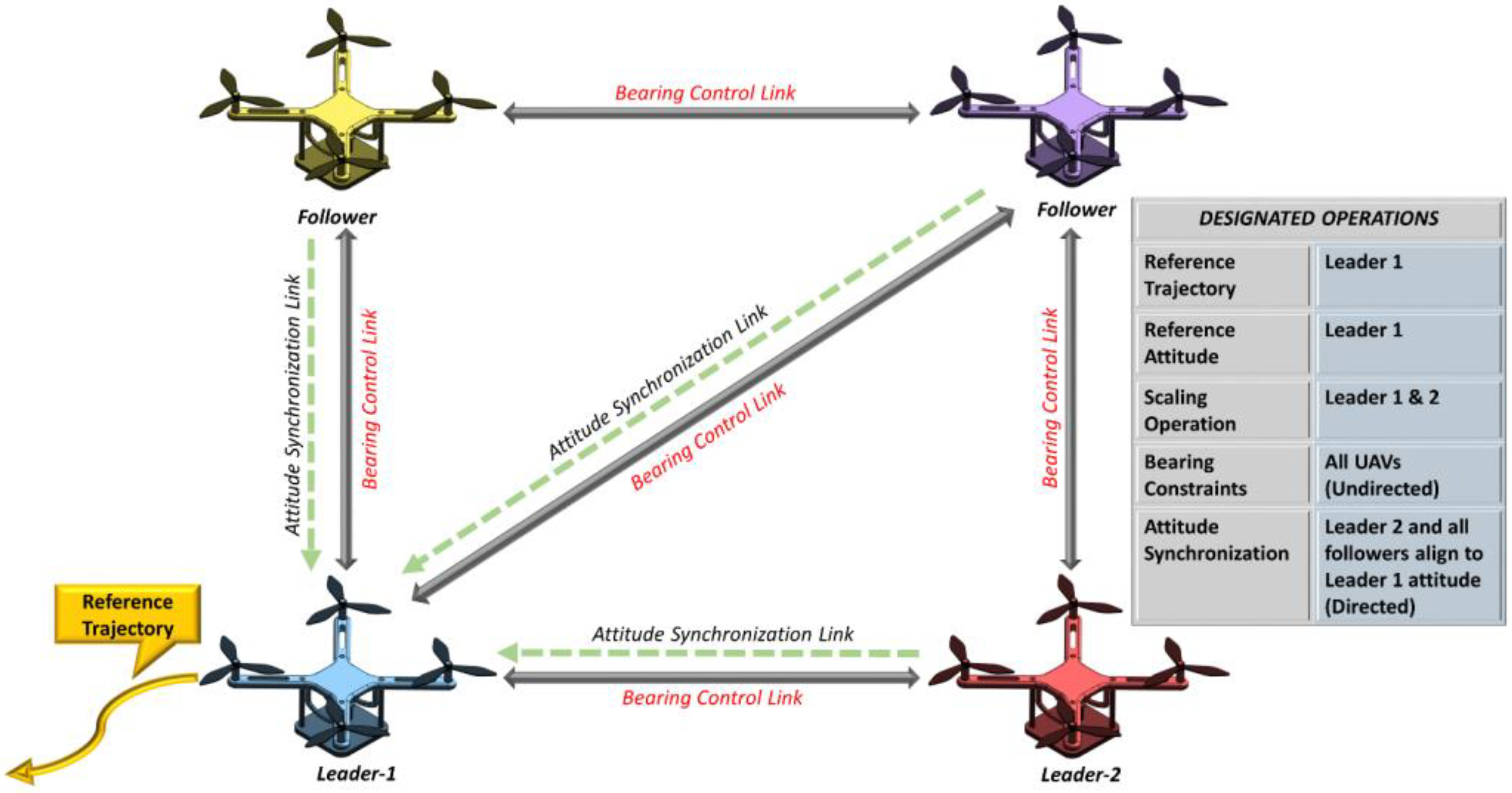
- A novel cascaded approach for distributed formation control of quadcopter UAVs was presented, consisting of an undirected bearing-based controller and a quaternion-based attitude synchronization controller working together in unison.
- The distributed attitude synchronization and bearing-based formation control law were designed for 3D formation control as compared to [22,23], which have only designed bearing-based controllers for 2D space. Moreover, the proposed scheme uses quaternion-based attitude control, which is much more robust than research that has used Euler angles such as [21,31].
- We designed our control method based on dynamic models of UAVs and undirected graph topology, a more robust technique as compared to [21,24,31], which only have used directed graph communications and kinematic models. The practical validation of the model was done using numerical simulations in MATLAB.
2. Preliminaries
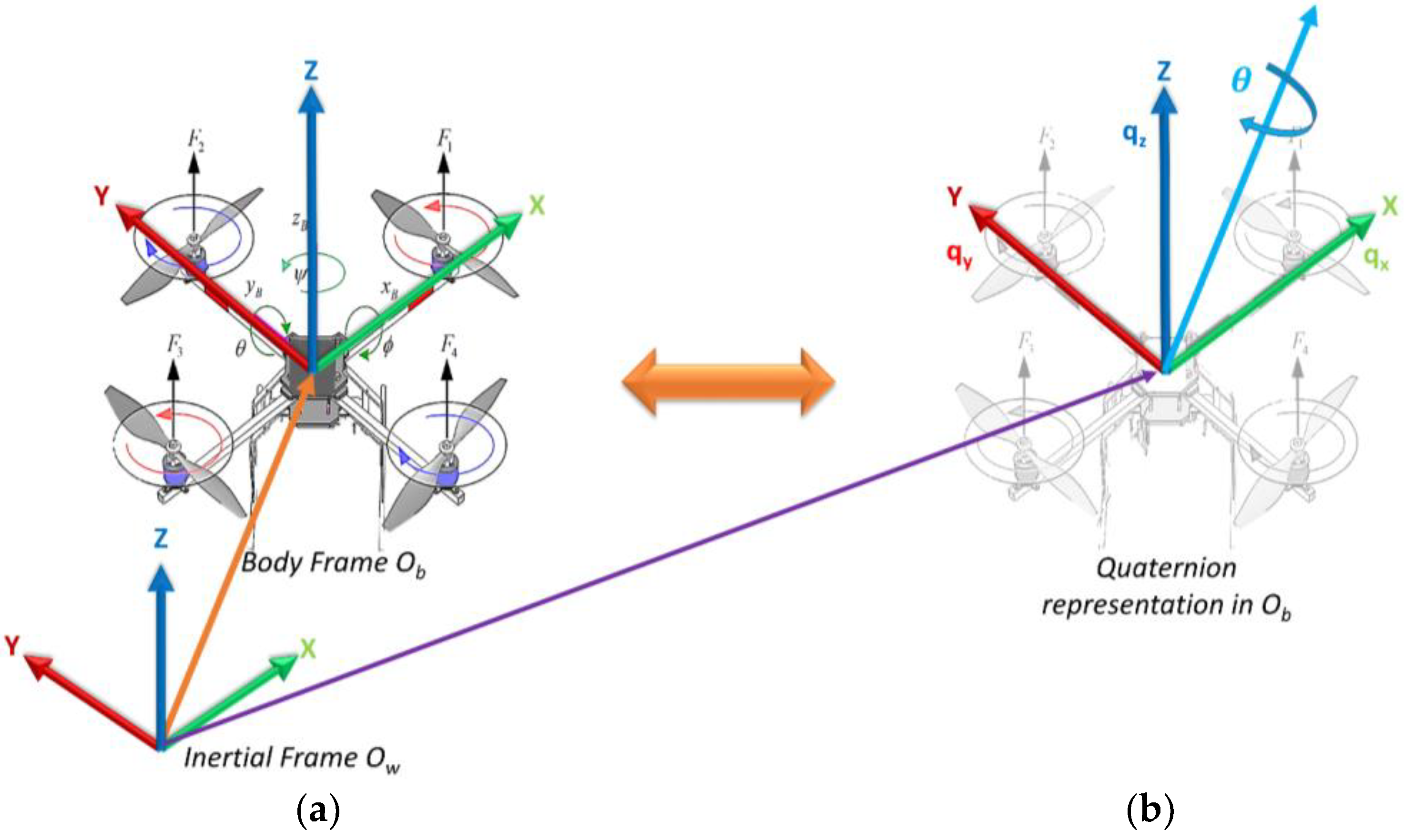
2.1. Quaternions
Quadcopter UAV Attitude Dynamics
2.2. Graph and Bearing Rigidity Theories
2.3. Problem Formulation
3. Proposed Control Scheme
3.1. Bearing-Based Controller
3.2. Attitude Synchronization Controller
4. Simulation Results
4.1. Case 1—Formation Acquisition
- (1)
- Objective: a swarm of four UAVs at random positions takes off and acquires a specific square shape under the control of proposed laws.
- (2)
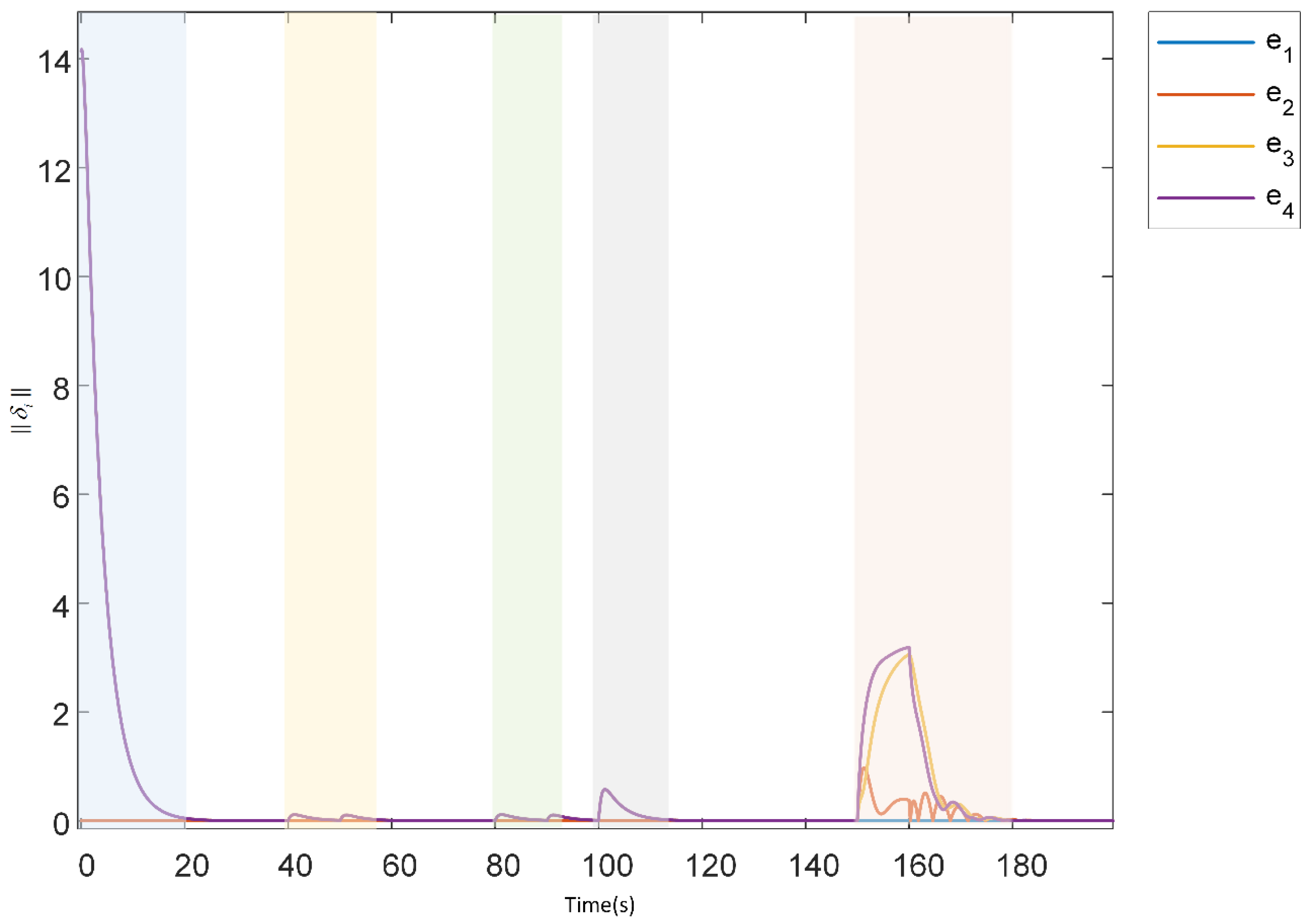
- Results: the target formation formed a designated square shape and was attained by implementing pre-defined bearing constraints between the agents as , , , , , , , , , and . The formation trajectories are given in Figure 5. The formation tracking error is shown in Figure 6 (section highlighted in blue), which asymptotically converged to zero from t = 0 to 20 s.
4.2. Case 2—Formation Scaling
- (1)
- Objective: to verify that formation can scale down (decrease size) and scale up (increase size) while translating in 3D space by still keeping formation-bearing constraints, inter-agent distances, and heading direction intact.
- (2)
- Results: the formation continued translation on the x-axis, scaled down at t = 40 s, and scaled up at t = 80 s to negotiate imaginary obstacles. This was achieved by adjusting and altering the distance and velocities of two leaders. Figure 5 depicts both scaling operations, and Figure 6 shows the convergence of formation tracking errors to zero (highlighted with yellow color for scaling down and with green color for scaling up).
4.3. Case 3—Altitude Maneuver
- (1)
- Objective: to verify that UAVs in the formation can also make an altitude descent while staying in the desired formation to negotiate an obstacle or follow a specific trajectory involving sudden altitude descent.
- (2)
- Results: after the scaling operation while translating in the x-axis direction, the formation abruptly descended its altitude in the z-axis direction in 3D space at t = 100 to 110 s by altering the velocity of leaders. The trajectory plot of UAVs is given in Figure 5, and the formation tracking error converged to zero asymptotically as shown in Figure 6 (highlighted with grey color).
4.4. Case 4—Formation Translational Rotation
- (1)
- Objective: to verify that formation while translating in 3D space can rotate its heading direction by altering the velocity of agents such that the swarm stays dynamically intact.
- (2)
- Results: in Figure 5 at t = 150 to 180 s, it can be seen that the final formation was rotated from the initial formation heading direction by altering the leader’s orientation so that the formation takes a translational rotation. The formation tracking error also converged to zero as shown in Figure 6 (section highlighted in orange color).
5. Discussion
6. Conclusions
Author Contributions
Funding
Institutional Review Board Statement
Informed Consent Statement
Data Availability Statement
Acknowledgments
Conflicts of Interest
References
- Bai, H.; Wen, J.T. Cooperative Load Transport: A Formation-Control Perspective. IEEE Trans. Robot. 2010, 26, 742–750. [Google Scholar] [CrossRef]
- Liu, G.P.; Zhang, S. A Survey on Formation Control of Small Satellites. Proc. IEEE 2018, 106, 440–457. [Google Scholar] [CrossRef]
- Dong, X.; Zhou, Y.; Ren, Z.; Zhong, Y. Time-Varying Formation Tracking for Second-Order Multi-Agent Systems Subjected to Switching Topologies With Application to Quadrotor Formation Flying. IEEE Trans. Ind. Electron. 2017, 64, 5014–5024. [Google Scholar] [CrossRef]
- Zhang, J.; Xing, J. Cooperative Task Assignment of Multi-UAV System. Chin. J. Aeronaut. 2020, 33, 2825–2827. [Google Scholar] [CrossRef]
- Wang, Y.; Zhang, T.; Cai, Z.; Zhao, J.; Wu, K. Multi-UAV Coordination Control by Chaotic Grey Wolf Optimization Based Distributed MPC with Event-Triggered Strategy. Chin. J. Aeronaut. 2020, 33, 2877–2897. [Google Scholar] [CrossRef]
- Zhen, Z.; Zhu, P.; Xue, Y.; Ji, Y. Distributed Intelligent Self-Organized Mission Planning of Multi-UAV for Dynamic Targets Cooperative Search-Attack. Chin. J. Aeronaut. 2019, 32, 2706–2716. [Google Scholar] [CrossRef]
- Zhang, P.; De Queiroz, M.; Cai, X. Three-Dimensional Dynamic Formation Control of Multi-Agent Systems Using Rigid Graphs. J. Dyn. Syst. Meas. Control Trans. ASME 2015, 137, 111006. [Google Scholar] [CrossRef]
- Sial, M.B.; Wang, S.; Wang, X.; Wyrwa, J.; Liao, Z.; Ding, W. Mission Oriented Flocking and Distributed Formation Control of UAVs. In Proceedings of the 16th IEEE Conference on Industrial Electronics and Applications, ICIEA 2021, Chengdu, China, 1–4 August 2021. [Google Scholar]
- Oh, K.K.; Park, M.C.; Ahn, H.S. A Survey of Multi-Agent Formation Control. Automatica 2015, 53, 424–440. [Google Scholar] [CrossRef]
- Lin, Z.; Ding, W.; Yan, G.; Yu, C.; Giua, A. Leader-Follower Formation via Complex Laplacian. Automatica 2013, 49, 1900–1906. [Google Scholar] [CrossRef]
- Lewis, M.A.; Tan, K.H. High Precision Formation Control of Mobile Robots Using Virtual Structures. Auton. Robot. 1997, 4, 387–403. [Google Scholar] [CrossRef]
- Hsieh, M.A.; Kumar, V.; Chaimowicz, L. Decentralized Controllers for Shape Generation with Robotic Swarms. Robotica 2008, 26, 691–701. [Google Scholar] [CrossRef]
- Mesbahi, M.; Egerstedt, M. Graph Theoretic Methods in Multiagent Networks; Princeton University Press: Princeton, NJ, USA, 2010. [Google Scholar]
- Giribet, J.I.; Colombo, L.J.; Moreno, P.; Mas, I.; Dimarogonas, D.V. Dual Quaternion Cluster-Space Formation Control. IEEE Robot. Autom. Lett. 2021, 6, 6789–6796. [Google Scholar] [CrossRef]
- CAI, Z.; WANG, L.; ZHAO, J.; WU, K.; WANG, Y. Virtual Target Guidance-Based Distributed Model Predictive Control for Formation Control of Multiple UAVs. Chin. J. Aeronaut. 2020, 33, 1037–1056. [Google Scholar] [CrossRef]
- Zou, Y.; Zhou, Z.; Dong, X.; Meng, Z. Distributed Formation Control for Multiple Vertical Takeoff and Landing UAVs with Switching Topologies. IEEE/ASME Trans. Mechatron. 2018, 23, 1750–1761. [Google Scholar] [CrossRef]
- CHEN, H.; WANG, X.; SHEN, L.; CONG, Y. Formation Flight of Fixed-Wing UAV Swarms: A Group-Based Hierarchical Approach. Chin. J. Aeronaut. 2021, 34, 504–515. [Google Scholar] [CrossRef]
- Trinh, M.H.; Pham, V.H.; Park, M.C.; Sun, Z.; Anderson, B.D.O.; Ahn, H.S. Comments on “Global Stabilization of Rigid Formations in the Plane [Automatica 49 (2013) 1436–1441]”. Automatica 2017, 77, 393–396. [Google Scholar] [CrossRef]
- Mou, S.; Belabbas, M.A.; Morse, A.S.; Sun, Z.; Anderson, B.D.O. Undirected Rigid Formations Are Problematic. IEEE Trans. Automat. Contr. 2016, 61, 2821–2836. [Google Scholar] [CrossRef]
- Cai, X.; Queiroz, M. De Adaptive Rigidity-Based Formation Control for Multirobotic Vehicles with Dynamics. IEEE Trans. Control Syst. Technol. 2015, 23, 389–396. [Google Scholar] [CrossRef]
- Li, X.; Wen, C.; Chen, C. Adaptive Formation Control of Networked Robotic Systems with Bearing-Only Measurements. IEEE Trans. Cybern. 2021, 51, 199–209. [Google Scholar] [CrossRef]
- Zhao, S.; Lin, F.; Peng, K.; Chen, B.M.; Lee, T.H. Distributed Control of Angle-Constrained Cyclic Formations Using Bearing-Only Measurements. Syst. Control Lett. 2014, 63, 12–24. [Google Scholar] [CrossRef]
- Basiri, M.; Bishop, A.N.; Jensfelt, P. Distributed Control of Triangular Formations with Angle-Only Constraints. Syst. Control Lett. 2010, 59, 147–154. [Google Scholar] [CrossRef]
- Zhao, S.; Zelazo, D. Bearing Rigidity and Almost Global Bearing-Only Formation Stabilization. IEEE Trans. Automat. Contr. 2016, 61, 1255–1268. [Google Scholar] [CrossRef]
- Li, Z.; Tnunay, H.; Zhao, S.; Meng, W.; Xie, S.Q.; Ding, Z. Bearing-Only Formation Control With Prespecified Convergence Time. IEEE Trans. Cybern. 2020, 52, 620–629. [Google Scholar] [CrossRef]
- Zhao, S.; Zelazo, D. Translational and Scaling Formation Maneuver Control via a Bearing-Based Approach. IEEE Trans. Control Netw. Syst. 2017, 4, 429–438. [Google Scholar] [CrossRef]
- Tron, R.; Thomas, J.; Loianno, G.; Daniilidis, K.; Kumar, V. A Distributed Optimization Framework for Localization and Formation Control: Applications to Vision-Based Measurements. IEEE Control Syst. 2016, 36, 22–44. [Google Scholar] [CrossRef]
- Gurbuz, A.C.; Cevher, V.; McClellan, J.H. Bearing Estimation via Spatial Sparsity Using Compressive Sensing. IEEE Trans. Aerosp. Electron. Syst. 2012, 48, 1358–1369. [Google Scholar] [CrossRef]
- Chen, Y.M.; Lee, J.H.; Yeh, C.C.; Mar, J. Bearing Estimation Without Calibration for Randomly Perturbed Arrays. IEEE Trans. Signal Process. 1991, 39, 194–197. [Google Scholar] [CrossRef]
- Carino, J.; Abaunza, H.; Castillo, P. Quadrotor Quaternion Control. In Proceedings of the 2015 International Conference on Unmanned Aircraft Systems, ICUAS 2015, Denver, Colorado, USA, 9–12 June 2015. [Google Scholar]
- Zhang, Y.; Wang, X.; Wang, S.; Tian, X. Distributed Bearing-Based Formation Control of Unmanned Aerial Vehicle Swarm via Global Orientation Estimation. Chin. J. Aeronaut. 2021, 35, 44–58. [Google Scholar] [CrossRef]
- Goldstein, H.; Poole, P.C.; Safko, J.L. Pearson Education—Classical Mechanics; Pearson: London, UK, 2002. [Google Scholar]
- Dantam, N.T. Robust and Efficient Forward, Differential, and Inverse Kinematics Using Dual Quaternions. Int. J. Rob. Res. 2021, 40, 1087–1105. [Google Scholar] [CrossRef]
- Qiuling, J.; Guangwen, L.; Jingchao, L. Formation Control and Attitude Cooperative Control of Multiple Rigid Body Systems. In Proceedings of the ISDA 2006: Sixth International Conference on Intelligent Systems Design and Applications, Jinan, China, 16–18 October 2006; Volume 2. [Google Scholar]
- Wang, P.K.C.; Hadaegh, F.Y.; Lau, K. Synchronized Formation Rotation and Attitude Control of Multiple Free-Flying Spacecraft. J. Guid. Control Dyn. 1999, 22, 28–35. [Google Scholar] [CrossRef]
- Abdelkader Abdessameud, A.T. Motion Coordination for VTOL Unmanned Aerial Vehicles: Attitude Synchronisation and Formation Control; Springer Science & Business Media: Berlin/Heidelberg, Germany, 2013. [Google Scholar]
- Zhao, S.; Zelazo, D. Bearing Rigidity Theory and Its Applications for Control and Estimation of Network Systems: Life beyond Distance Rigidity. IEEE Control Syst. 2019, 39, 66–83. [Google Scholar] [CrossRef]
- Trinh, M.H.; Zhao, S.; Sun, Z.; Zelazo, D.; Anderson, B.D.O.; Ahn, H.S. Bearing-Based Formation Control of a Group of Agents with Leader-First Follower Structure. IEEE Trans. Automat. Contr. 2019, 64, 598–613. [Google Scholar] [CrossRef]
- Ren, W. On Consensus Algorithms for Double-Integrator Dynamics. IEEE Trans. Automat. Contr. 2008, 53, 1503–1509. [Google Scholar] [CrossRef]
- Ren, W. Distributed Attitude Alignment in Spacecraft Formation Flying. Int. J. Adapt. Control Signal Process. 2007, 21, 95–113. [Google Scholar] [CrossRef]
- Huang, Y.; Meng, Z. Bearing-Based Distributed Formation Control of Multiple Vertical Take-Off and Landing UAVs. IEEE Trans. Control Netw. Syst. 2021, 8, 1281–1292. [Google Scholar] [CrossRef]


| Parameter | Value |
|---|---|
| m | 0.80 |
| [1,0.1,0.1; 0.1,0.1,0.1; 0.1,0.1,0.9] | |
| [0,1,1,1; 1,0,1,1; 1,1,0,1; 1,1,1,0] | |
| 1 | |
| 10 | |
| 0.5 | |
| 2 |
Publisher’s Note: MDPI stays neutral with regard to jurisdictional claims in published maps and institutional affiliations. |
© 2022 by the authors. Licensee MDPI, Basel, Switzerland. This article is an open access article distributed under the terms and conditions of the Creative Commons Attribution (CC BY) license (https://creativecommons.org/licenses/by/4.0/).
Share and Cite
Sial, M.B.; Zhang, Y.; Wang, S.; Ali, S.; Wang, X.; Yang, X.; Liao, Z.; Yang, Z. Bearing-Based Distributed Formation Control of Unmanned Aerial Vehicle Swarm by Quaternion-Based Attitude Synchronization in Three-Dimensional Space. Drones 2022, 6, 227. https://doi.org/10.3390/drones6090227
Sial MB, Zhang Y, Wang S, Ali S, Wang X, Yang X, Liao Z, Yang Z. Bearing-Based Distributed Formation Control of Unmanned Aerial Vehicle Swarm by Quaternion-Based Attitude Synchronization in Three-Dimensional Space. Drones. 2022; 6(9):227. https://doi.org/10.3390/drones6090227
Chicago/Turabian StyleSial, Muhammad Baber, Yuwei Zhang, Shaoping Wang, Sara Ali, Xinjiang Wang, Xinyu Yang, Zirui Liao, and Zunheng Yang. 2022. "Bearing-Based Distributed Formation Control of Unmanned Aerial Vehicle Swarm by Quaternion-Based Attitude Synchronization in Three-Dimensional Space" Drones 6, no. 9: 227. https://doi.org/10.3390/drones6090227