Proceeding Paper

Development of Short-Circuit Protection in Hands-On Electronic Training Set for Vocational Education †

Graduate School of Vocational Education, National Yunlin University of Science and Technology, Yunlin 64002, Taiwan
Presented at the 5th International Conference on Vocational Education Applied Science and Technology 2022, Teluk Betung, Indonesia, 26–28 October 2022.
Proceedings 2022, 83(1), 25; https://doi.org/10.3390/proceedings2022083025
Published: 26 December 2022

Abstract

:
Hands-on activities are one of the characteristics of vocational learning. Learners will be triggered to activate their cognitive and psychomotor aspects with hands-on activities. These activities involve training sets to support students in understanding some specific vocational topics. The level of student understanding can be classified as the mastery of vocational-specific skills. Learners with minimum vocational skills can be grouped as beginners. However, beginner learning in vocational training is a considerable risk, and training sets have a high potential for damage. Electronic training sets are especially prone to voltage installation errors, resulting in fatal damage. Therefore, this study developed a relay-based short-circuit protection for the electronic training set. The development process consists of identification, designing, circuit processing, and circuit testing. This circuit was equipped with relay protection, a buzzer, and an LED short indicator. Drop-voltage was utilized during the short-circuit to activate relay protection. A Zener diode (3V3 and 5V6) was employed as a drop-voltage sensor and Op-Amp comparator. The test results reveal the circuit’s functionality to protect against short-circuits on 5 V and 12 V direct currents. The operating principle is that before the voltage hits zero (0), the relay will cut off the voltage line between the training circuit and the power supply. This reduces the risk of damage due to faulty circuits or misconnections.

1. Introduction

Vocational schools allow students to develop skills in specific fields [1]. As a result, students are equipped with cognitive and psychomotor abilities to become experts in one occupational field [2,3]. Therefore, psychomotor skills become a point of emphasis in learning in vocational schools. One way to generate psychomotor abilities is to actively utilize learning that triggers students to perform a skill with both hands, more commonly known as hands-on activity [4,5].
Hands-on activity is essential in learning today at all levels of education, from kindergarten school to higher education. The focus of learning in vocational schools with a high level of education with hands-on activities requires appropriate and adequate equipment or media [6]. For example, learning media such as training sets are mandatory for vocational schools to facilitate students’ skill development. Therefore, learning media has a vital role in developing students’ abilities [7].
The term “learning media” refers to a device or facility that helps with communication in the learning process [8]. In other words, learning media is a tool that can be employed to help convey information or knowledge from teachers to students. Meanwhile, good learning media is media whose development process goes through selection, design, and production, and is used as part of the instructional system [9]. Based on this, good learning media must result from a correct and appropriate design.
Learning media are categorized into several groups, one of which is electronic training sets. Electronic modules train learners to understand circuit work, from designing, assembling, and recording to analyzing practical results. The electronic training set requires voltage from the power supply to operate the entire circuit. Furthermore, this supply voltage becomes vital for the training set circuit, and the supply voltage requirement is adjusted to the electronic circuit’s specifications.
The voltage source from the power supply is what makes the electronic circuit work. Therefore, the voltage source must be appropriately maintained to avoid damage. Two possibilities can cause a voltage source to malfunction: overload and short circuit. A short circuit is a type of damage to an electronic circuit power supply system that occurs due to being hit by a lightning strike or the voltage being too large [10]. In addition, overloading for a certain period can cause the power supply circuit to overheat, and then cause damage.
In learning media development, it is mandatory to pay attention to safety guidelines for users and devices. Protection for users is provided by means of appropriate signs or standard operating procedures (SOP). At the same time, not only SOPs of practice modules require a good safety system or facilities [11]. The safety system consists of materials, an ergonomic shape, and an electronic safety device. Electronic protection/safety can be divided into overcurrent protection, short circuit protection, protection from overheating, and protection from installation errors [12].
One focus of this developmental research is to develop a protection system for the electronic circuit module from the occurrence of short circuits. Observations and data collection results from courses that use electronic circuit modules state that human errors which cause damage to occur due to incorrect voltage source installation. One of the errors is the occurrence of a short circuit in the power supply line, and the fault cannot be directly seen or detected. As a result, in the long term, this can cause damage to the electronic circuit module or the power supply circuit.
Based on this background explanation, this developmental research is designing and assembling short-voltage protection circuits. Furthermore, focusing on safety for the direct voltage will be utilized for electronic training sets in learning media in vocational schools.

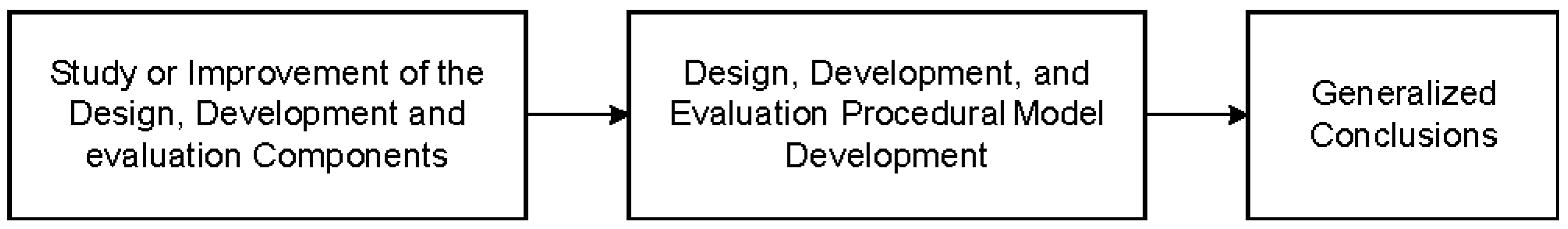
2. Research Methodology

This study employed a Developmental Research approach. Developmental research is research to design, develop, and evaluate instructional programs, processes, and products that must meet the criteria of consistency and effectiveness [13]. Figure 1 is the Developmental Research model adopted in this study.
Stage 1: We studied the design, development, and evaluation components, including studying the voltage training set to be secured, short voltage detection system, and direct current (DC) voltage safety principle. Next, the necessary components are identified.
Phase 2: The design, development, and evaluation of procedural model development, including designing an electronic system for short circuit detection and protection, were completed. Afterwards, a thorough design review was carried out, and an electronic circuit was assembled on a printed circuit board. The final step of this stage was testing on the board circuit to obtain the performance through functionality testing, as well as detection response for short circuit safety.
Stage 3: We present our generalized conclusion, including concluding the short circuit voltage safety circuit test results, based on the data obtained.
The research was conducted at the Power Electronics Laboratory, Department of Electrical Engineering Education, Faculty of Engineering, Universitas Negeri Yogyakarta. The test involves several measuring instruments, such as a multimeter and an oscilloscope.

3. Result and Discussion

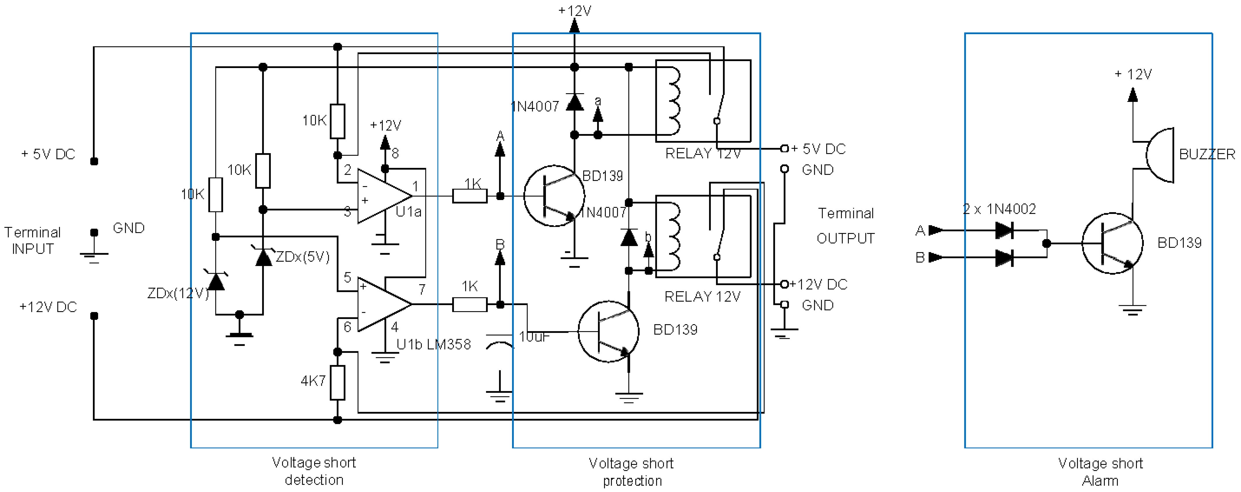
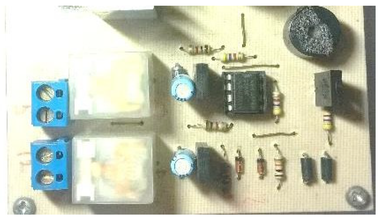
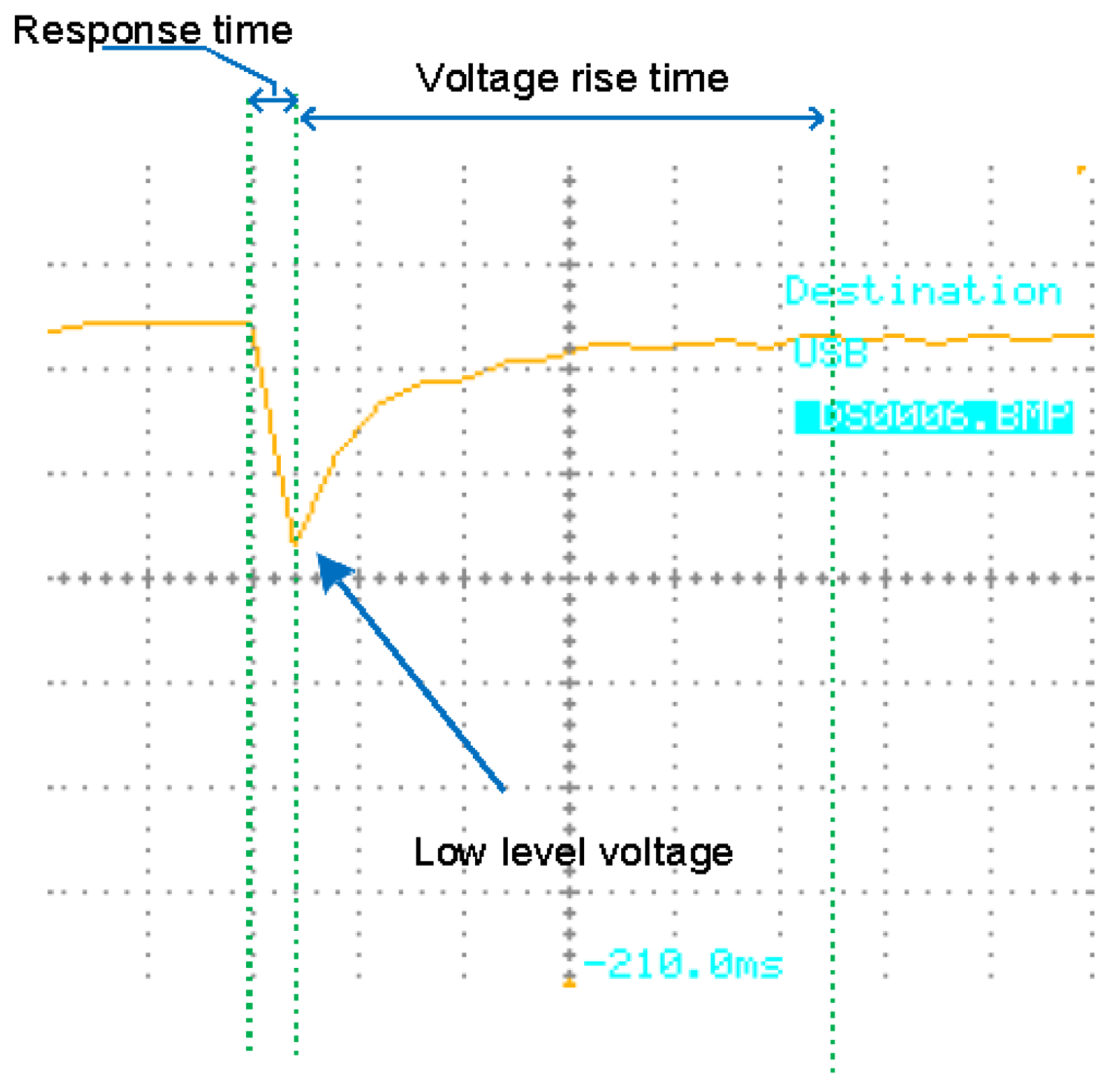
3.1. Developmental Result

The results of the assembled circuit development were divided into three main parts (as in Figure 2), namely Short Voltage Detection (SVD), Short Voltage Protection (SVP), and Short Voltage Alarm (SVA). The SVD section consisted of LM358 as a comparator and a Zener diode as a reference voltage of the comparator. If the input voltage was detected to be lower than the comparator voltage, it would trigger the comparator to generate a trigger signal to activate the protection system.
The second part was the SVP, which consisted of a driver transistor and a safety relay. The function of the transistor driver was as a switch to activate the safety relay. This transistor would become active if it received a trigger signal from the comparator in the short circuit voltage detection circuit. At the same time, the relay was selected with one common and two output terminals. Furthermore, the relay was used in the Normally Close (NC) position as a connector of the supply voltage, while it was used in Normally Open (NO) as a voltage breaker in the event of a short circuit.
The third part is the SVA, which consisted of a one-way diode, transistor, and buzzer. The function of the one-way diode was to prevent the trigger signal back from one of the trigger lines to the SVP circuit. This was because the two trigger signal outputs from the SVD were connected through a one-way diode to activate a buzzer. The transistor here was used as a switch that would become active if it were to receive a trigger from the SVD circuit. If the transistor is active, the buzzer will also work, generating sound.
A prominent note from this research is that the Zener in the SVD circuit was varied to determine the fast response of the short voltage detection.
After going through the study of the design and component stages, the development of hardware into assemblies on a circuit board was carried out according to the proper layout rules, as shown in Figure 3. The applied rules included arranging the circuit connection terminals on the edge, so that the other active components would have a safe distance.
The next stage is the evaluation or testing stage of the circuit. The oscilloscope was used to read the circuit response signal to the short voltage time, as shown in Figure 4. The response time determines the most effective Zener diode value for the protected supply voltage. The response time in Figure 4 is divided into two parts: the work response time, which is seen from high to low waveforms (falling edge), and the response time back to a normal voltage, which is seen from low/common to high waves (rising edge). At the same time, the lowest stress point was taken at the bottom of the lowest point of the waveform.
The Zener typical voltage used for 5V regulated supply is 2.7V to 4.7V. Therefore, if the Zener cut voltage was more than 5V, the sensor in a comparator would always be active. Table 1 shows the average time obtained. The short-circuit sensor response time was 4 ms before the relay cut off the voltage, indicating a short circuit. The short circuit experiment was performed five times on each Zener typical voltage in order to obtain accurate data.
As for the time it took for voltage to rise to normal levels (5V or 12V DC), the results varied (Table 2), especially on the SVD sensor, at a voltage of 12V. At a voltage of 5V, the relative time was the same (4 ms). At the same time, the data on the rising time of the voltage rises returned at the 12V level, growing smaller on the 10V SVD Zener, i.e., with an average of 16 ms.
The final data to be observed was the lowest response voltage of the SVD circuit, as shown in Table 3. When a short circuit occurs, the voltage drop (falling) is close to zero. If a positive voltage occurs, a long-lasting short circuit will damage the regulator circuit. This is what must be avoided in the process of short circuits. By detecting the lowest voltage, as shown in Table 3, it can be determined which detection sensor is the safest. The higher the low voltage when short-circuited, the safer the training set circuits for learning. Table 3 shows that the highest voltage response was 6V, and the lowest voltage response was 0.6 V.

3.2. Discussion

The short circuit protection for the 5VDC voltage with the best working response time was 4 ms, and the voltage rising time to normal levels was 4 ms. These data show that the speed of the system in detecting and responding with protection measures in the event of a short circuit worked well. The lowest voltage occurred when the short circuit was 3.6 V, with a 3.3 V typical Zener diode voltage. The circuit worked very well if the lowest voltage was higher than the ground voltage (0). Figure 5A is a good performance response waveform of a short circuit breaker with a 3.3 V typical Zener diode voltage.
The orange line in Figure 5A shows the response time and the rising voltage time to normal at the output of the IC regulator when a short circuit occurred. The blue line indicated that the relay was working to break the voltage line by the sensor in SVD. However, by disconnecting the voltage from the source, it takes time to reach 0 due to the mechanical relay.
Furthermore, short-circuit protection for the 12VDC supply showed the best response time, at 4 ms, and also showed a rising voltage time to normal levels of 12 ms. This rising time is much longer than the 5VDC supply. The long response time is because the higher the voltage, the more time the process of charging the capacitor in the regulator and returning the rising voltage to normal takes. The lowest voltage of the short circuit protection at 12VDC supply voltage was 6 V with a 5.6 V typical Zener diode. Although the Zener diode was enlarged, the best lowest voltage value was the 5.6 V typical Zener voltage.
The protection system in an electronic or electrical system must be made to maintain the user’s safety and the device itself. Various types of protection are used in electrical science, including protection components such as fuses [14], mechanical systems such as circuit breakers [15], or relay-based or solid-state electronic protection systems [16]. Each type of protection has its advantages and uses to its range specification. Hence, selecting the proper electrical protection to provide safety for the user and the device reduces the cost of maintaining the system [17].
The protection system in this study was selected using a relay (mechanical) with a good lifetime capability and reliability to high short-circuit currents [18]. In addition, the relay protection system, combined with electronic SVD, will increase work effectiveness and reduce maintenance costs [17]. This is because this system was built so that when a short voltage occurs, it will work to cut off the power supply line, and if it is an open-short voltage, the system will reset. This occurs so that there are no components that must be replaced after a short voltage occurs, unlike with the fuse component, which breaks after an open-short voltage and must be replaced again.
The protection system developed in this study performs effectively and provides optimal device safety. This is expressed in Figure 5, which shows that the voltage during a short circuit does not reach zero (0). Therefore, the power supply system will not be burdened by over currents for a long time, which will cause damage. Therefore, in addition to guaranteed protection for the training set, it will also have a comfortable impact during students’ hands-on activities for developing skills in specific fields.
Student activities, such as assembling an electronic circuit (hands-on) on the training set, will be protected from damage due to short circuits. Student anxiety related to the potential for damage to the training set will be reduced [19]. Therefore, our strategy will increase students’ confidence to participate in hands-on activities [20].

4. Conclusions

The relay and buzzer actively indicated that the short voltage protection circuit works well. More specifically, the best response time for 5VDC supply was 8 ms at 3.3 V typical Zener, and the best response time for 12VDC supply was 16 ms at 5.6 V typical Zener. However, using the correct typical voltage of the Zener diode affects the time that protection circuit performance needs to break the power supply line.

Limitation and Future Suggestion

This study uses a Developmental Research approach that focuses on designing, developing, and testing tools. As a tool that supports hands-on learning activity, this study tests until the circuit functionality stage. Therefore, further research can be carried out by testing the learning process with a sufficient sample of students, in order to determine the benefits of the device for the related dependent variable.

Funding

This research received no external funding.

Institutional Review Board Statement

Not applicable.

Informed Consent Statement

Not applicable.

Data Availability Statement

This study did not report any data.

Conflicts of Interest

The author declares that they have no competing interests.

References

  1. Smirnova, Z.V.; Vaganova, O.I.; Loshkareva, D.A.; Konyaeva, E.A.; Gladkova, M.N. Practice-oriented approach implementation in vocational education. IOP Conf. Ser. Mater. Sci. Eng. 2019, 483, 012003. [Google Scholar] [CrossRef]
  2. Rahman, M.H.; Iriani, T.; Widiasanti, I. The Analysis of Cognitive and Psychomotor Domains in Basic Competence in the Subject of Land Measurement Engineering in Curriculum Vocational Schools—Area of Expertise Construction and Property. in International Conference on Humanities, Education, and Social Sciences. KnE Soc. Sci. 2020, V4, 186–193. [Google Scholar] [CrossRef]
  3. Widasari, S.R.; Somad, P.; Soendari, T. Development of Vocational Programs Culinary Based on Competence of the World of Work. Adv. Sci. Lett. 2019, 25, 162–165. [Google Scholar] [CrossRef]
  4. Ajayi, V.O.; Ogbeba, J. Effect of Gender on Senior Secondary Chemistry Students’ Achievement in Stoichiometry Using Hands-On Activities. Am. J. Educ. Res. 2017, 5, 839–842. [Google Scholar] [CrossRef] [Green Version]
  5. Witarsa, R.; Rahayu, G.D.S.; Sriningsih, N.; Nurhayati, N.; Tellusa, S.; Parwati, P. Meningkatkan kemampuan aspek psikomotorik siswa sekolah dasar melalui hands on activity di kota cimahi. J. Basicedu. 2017, 1, 62–72. [Google Scholar] [CrossRef]
  6. Berman, E.T.; Hamidah, I.; Mulyanti, B.; Setiawan, A. Low Cost and Portable Laboratory Kit for Practicum Learning of Air Conditioning Process in Vocational Education. J. Tech. Educ. Train. 2021, 13, 133–145. Available online: https://penerbit.uthm.edu.my/ojs/index.php/JTET/article/view/9091 (accessed on 10 October 2022).
  7. van Merriënboer, J.J.G.; Kirschner, P.A. Ten Steps to Complex Learning: A Systematic Approach to Four-Component Instructional Design, 3rd ed.; Routledge: New York, NY, USA, 2017. [Google Scholar] [CrossRef]
  8. Heinich, R. Instructional Media and Technologies for Learning; Pearson Education Ltd.: London, UK, 2002; p. 377. [Google Scholar]
  9. Mustholiq, I.; Sukir, S.; Ariade Chandra, N. Pengembangan Media Pembelajaran Interaktif Berbasis Multimedia Mata Kuliah Dasar Listrik. J. Pendidik. Teknol. Kejuru. 2007, 16, 1–18. [Google Scholar] [CrossRef]
  10. Gavrilovs, G.; Vītoliņa, S. Identification of Power Transformer’s Failure and Risk Source. In Proceedings of the 52nd Annual International Scientific Conference of Riga Technical University, Riga, Latvia, 14 October 2011; pp. 29–30. [Google Scholar]
  11. Sadik, D.-P.; Colmenares, J.; Tolstoy, G.; Peftitsis, D.; Bakowski, M.; Rabkowski, J.; Nee, H.-P. Short-Circuit Protection Circuits for Silicon-Carbide Power Transistors. IEEE Trans. Ind. Electron. 2015, 63, 1995–2004. [Google Scholar] [CrossRef]
  12. Abirami, P.; George, M.L. Electronic Circuit Breaker for overload protection. In Proceedings of the 2016 International Conference on Computation of Power, Energy, Information and Communication, ICCPEIC 2016, Chennai, India, 20–21 April 2016; pp. 773–776. [Google Scholar] [CrossRef]
  13. Richey, R.C. Developmental Research: The Definition and Scope. In Proceedings of the 1994 National Convention of the Association for Educational communications and Technology, Nashville, TN, USA, 16–20 February 1994. [Google Scholar]
  14. Cline, C.; Stultz, J. Fuse protection of DC systems. In Proceedings of the American Power Conference, Illinois Institute of Technology, Chicago, IL, USA, 18–20 April 1995; Volume 57, p. 20. [Google Scholar]
  15. Qi, L.L.; Antoniazzi, A.; Raciti, L.; Leoni, D. Design of Solid-State Circuit Breaker-Based Protection for DC Shipboard Power Systems. IEEE J. Emerg. Sel. Top. Power Electron. 2016, 5, 260–268. [Google Scholar] [CrossRef]
  16. Piesciorovsky, E.C.; Schulz, N.N. Fuse relay adaptive overcurrent protection scheme for microgrid with distributed generators. IET Gener. Transm. Distrib. 2017, 11, 540–549. [Google Scholar] [CrossRef]
  17. Liu, S.; Popov, M. Development of HVDC system-level mechanical circuit breaker model. Int. J. Electr. Power Energy Syst. 2018, 103, 159–167. [Google Scholar] [CrossRef]
  18. Zubic, S.; Gajic, Z.; Kralj, D. The Impact of Line Protection Operate Time on Circuit Breaker Wear. In Proceedings of the 16th International Conference on Developments in Power System Protection (DPSP 2022), Hybrid Conference, Newcastle, UK, 7–10 March 2022; Volume 2022, pp. 404–409. [Google Scholar] [CrossRef]
  19. Sharpe, L.; Todd, J.; Scott, A.; Gatzounis, R.; Menzies, R.E.; Meulders, A. Safety behaviours or safety precautions? The role of subtle avoidance in anxiety disorders in the context of chronic physical illness. Clin. Psychol. Rev. 2022, 92, 102126. [Google Scholar] [CrossRef] [PubMed]
  20. Bommer, C.; Sullivan, S.; Campbell, K.; Ahola, Z.; Agarwal, S.; O’Rourke, A.; Jung, H.S.; Gibson, A.; Leverson, G.; Liepert, A.E. Pre-simulation orientation for medical trainees: An approach to decrease anxiety and improve confidence and performance. Am. J. Surg. 2018, 215, 266–271. [Google Scholar] [CrossRef]
Figure 1. Developmental Research procedures [13].
Proceedings 83 00025 g001
Figure 2. Short voltage protection circuit.
Proceedings 83 00025 g002
Figure 3. DC short voltage protection assembled.
Proceedings 83 00025 g003
Figure 4. Short circuit protection signal on the power supply line to the training set.
Proceedings 83 00025 g004
Figure 5. Signal response of short voltage protection ((A) 5V supply; (B) 12 supply).
Proceedings 83 00025 g005
Table 1. Response time SVD circuit.
Response Time (Falling Edge) in ms
Data No.Zener 2.7VZener 3.3VZener 3.9VZener 4.7VZener 5.6VZener 7.5VZener 10V
Reg
5V
Reg
12V
Reg
5V
Reg
12V
Reg
5V
Reg
12V
Reg
5V
Reg
12V
Reg
5V
Reg
12V
Reg
5V
Reg
12V
Reg
5V
Reg
12V
148444444x4x4x4
248444444x4x4x4
344444444x8x4x4
444444444x4x4x4
548444444x4x8x4
mean46.4444444x4.8x4.8x4
Notes: x = Zener voltage more than regulator specification voltage.
Table 2. Time of voltage returns to normal.
Voltage Rise Time to Normal Level (Rising Edge) in ms
Data No.Zener 2.7VZener 3.3VZener 3.9VZener 4.7VZener 5.6VZener 7.5VZener 10V
Reg
5V
Reg
12V
Reg
5V
Reg
12V
Reg
5V
Reg
12V
Reg
5V
Reg
12V
Reg
5V
Reg
12V
Reg
5V
Reg
12V
Reg
5V
Reg
12V
1442426426420x16x16x12
2442426426422x18x16x16
3446426426420x12x20x16
4446426426420x16x16x16
5442426426420x16x12x16
mean443.6426426420.4x15.6x16x15.2
Notes: x = Zener voltage more than regulator specification voltage.
Table 3. Lowest voltage responses.
Low-Level Voltage in V
Data No.Zener 2.7VZener 3.3VZener 3.9VZener 4.7VZener 5.6VZener 7.5VZener 10V
Reg
5V
Reg
12V
Reg
5V
Reg
12V
Reg
5V
Reg
12V
Reg
5V
Reg
12V
Reg
5V
Reg
12V
Reg
5V
Reg
12V
Reg
5V
Reg
12V
10.63.5121.4412x3.5x1.5x1
213.5231.213.53.5x3x4x1
31.81.52.41.52112x6x4x2.5
41.81.53.62.51.4213.5x3.5x2x1.5
50.43.52.821313.5x4x2.5x1.5
mean1.122.72.362.21.42.21.52.9x4x2.8x1.5
Notes: x = Zener voltage more than regulator specification voltage.
Disclaimer/Publisher’s Note: The statements, opinions and data contained in all publications are solely those of the individual author(s) and contributor(s) and not of MDPI and/or the editor(s). MDPI and/or the editor(s) disclaim responsibility for any injury to people or property resulting from any ideas, methods, instructions or products referred to in the content.

