Article

Smooth and Efficient Path Planning for Car-like Mobile Robot Using Improved Ant Colony Optimization in Narrow and Large-Size Scenes

1
School of Management, Huazhong University of Science and Technology, 1037 Luoyu Road, Wuhan 430074, China
2
The State Key Laboratory of New Textile Materials and Advanced Processing Technologies, Wuhan Textile University, 1 Yangguang Avenue, Wuhan 430200, China
3
Hubei Institute of Measurement and Testing Technology, 2 Maodianshan Middle Road, Wuhan 430223, China; liyujiang2023@163.com
4
Hubei Province Fibre Inspection Bureau, 6 Gongping Road, Wuhan 430064, China
5
Hubei Key Laboratory of Digital Textile Equipment, Wuhan Textile University, 1 Yangguang Avenue, Wuhan 430200, China
6
School of Computer Science and Artificial Intelligence, Wuhan Textile University, 1 Yangguang Avenue, Wuhan 430200, China
*
Author to whom correspondence should be addressed.
Fractal Fract. 2024, 8(3), 157; https://doi.org/10.3390/fractalfract8030157
Submission received: 31 January 2024 / Revised: 4 March 2024 / Accepted: 7 March 2024 / Published: 10 March 2024
(This article belongs to the Special Issue Applications of Fractional-Order Calculus in Robotics)

Abstract

:
Car-like mobile robots (CLMRs) are extensively utilized in various intricate scenarios owing to their exceptional maneuverability, stability, and adaptability, in which path planning is an important technical basis for their autonomous navigation. However, path planning methods are prone to inefficiently generate unsmooth paths in narrow and large-size scenes, especially considering the chassis model complexity of CLMRs with suspension. To this end, instead of traditional path planning based on an integer order model, this paper proposes fractional-order enhanced path planning using an improved Ant Colony Optimization (ACO) for CLMRs with suspension, which can obtain smooth and efficient paths in narrow and large-size scenes. On one hand, to improve the accuracy of the kinematic model construction of CLMRs with suspension, an accurate fractional-order-based kinematic modelling method is proposed, which considers the dynamic adjustment of the angle constraints. On the other hand, an improved ACO-based path planning method using fractional-order models is introduced by adopting a global multifactorial heuristic function with dynamic angle constraints, adaptive pheromone adjustment, and fractional-order state-transfer models, which avoids easily falling into a local optimum and unsmooth problem in a narrow space while increasing the search speed and success rate in large-scale scenes. Finally, the proposed method’s effectiveness is validated in both large-scale and narrow scenes, confirming its capability to handle various challenging scenarios.

1. Introduction

Path planning is a critical technology in the field of mobile robotics, enabling a mobile robot to efficiently navigate from its starting point to a designated target while circumventing obstacles within a given environment. It serves as a fundamental component of autonomous navigation and intelligent decision-making in mobile robot systems [1,2,3]. Meanwhile, Car-Like Mobile Robots (CLMRs) play an important role in the fields of warehousing and logistics, inspection, and distribution, etc. [4,5,6], and their chassis is equipped with a steering mechanism and suspension system [7], which makes CLMRs have good load capacity, passability, and flexibility. CLMRs are commonly utilized in environments characterized by a combination of large-scale areas and narrow spaces. Examples include neighborhoods with narrow alleys, dynamic manufacturing plants, or wild landscapes with dense vegetation [8,9]. These types of scenes impose greater demands on the path planning capabilities of CLMRs, requiring them to efficiently and accurately plan smooth paths.
Recently, path planning methods have emerged as a highly prominent area of research, captivating the attention of scholars worldwide, and researchers have extensively explored and developed innovative techniques across a diverse range of scenarios and for various types of robots [10,11,12]. In general, research on path planning usually focuses on two major aspects: the construction of the robot chassis model and the optimization of path planning methods. Fortunately, the fractional-order method is commonly used for modelling and optimization, which is a mathematical tool dealing with non-integer order calculus [13,14,15,16]. It extends the traditional integer order calculus by allowing derivatives or integrals of non-integer orders to exist in the model. Fractional-order methods have gained significant attention in capturing the behavior of complex nonlinear systems. These methods offer a more accurate representation of system dynamics by incorporating fractional-order differential equations, which enable the modelling of properties like nonlocal dependence and nonsmooth behavior, allowing fractional-order models to better fit the behavior of real systems and provide more accurate predictions and analyses [17,18,19,20]. Therefore, this paper aims to utilize the fractional-order approach to extend the conventional path planning method based on an integer-order model, to devise a path planning scheme that is not only smoother but also more efficient.
In terms of robot chassis model construction, it can usually be categorized into kinetic model and kinematic model construction [21]. In path planning, kinematic model construction is widely used in mobile robot path planning because it is efficient and practical [22], unless robots involving special loads or structures need to consider kinetic models [23]. Traditional kinematic model construction assumes that the steering and drive mechanisms of the vehicle are rigid bodies and uses an integer order approach for model construction [24]. This approach simplifies the modelling and computational process but also poses the problem that once the structure and parameters of the robot chassis have been determined, the angle constraints are fixed. However, for the kinematic modelling of a CLMR, the traditional approach is not applicable because CLMRs are usually equipped with shock-absorbing suspensions on the drive and steering mechanisms to enhance passability and stability [7]. This leads to changes in the chassis structure when steering or crossing obstacles, which makes the angle constraints in the kinematic model time-varying. Only by more accurately describing the time-varying angle constraints can the CLMR’s ability to move in a narrow space be improved. The accurate description of time-varying systems using fractional-order methods offers a valuable opportunity to enhance the CLMR’s maneuverability in narrow spaces. In this regard, this paper aims to make a significant contribution by incorporating dynamic factors, such as chassis suspension, into the precise construction of the fractional-order kinematic model.
There are many different path planning methods available [25], mainly including graph-search-based methods (e.g., A* algorithm [26]), stochastic path planning methods (e.g., Rapidly-Exploring Random Tree, RRT [27]), and optimization algorithms (e.g., Ant Colony Optimization, ACO [28], and Genetic Algorithm, GA [29]). The above path planning methods are usually used for global planning, but for dynamic obstacles, they are combined with local planning in practical applications, such as dynamic window approaches [30]. Graph-search-based methods utilize a heuristic function to assess the priority of nodes within a graph, enabling the identification of an optimal path by traversing the nodes. This approach is known for its high search efficiency and accuracy, making it particularly suitable for small-scale path planning problems. Besides, stochastic path planning methods employ random sampling and tree expansion techniques to swiftly explore feasible paths and gradually approach the desired goal position. These methods excel in high-dimensional environments and complex terrains but are susceptible to planning failures in narrow scenarios. Alternatively, optimization algorithms iteratively search for either the global optimal solution or a near-optimal solution through an optimization process [31]. These algorithms aim to find the most optimized path by iteratively refining the solution. With the advantages of a global search ability, complex scene adaptability and learning ability, ACO has a strong solving ability in path planning problems and is widely used in real-world scenarios [10].
A lot of good research has been done to use ACOs in a better way, and usually, their efficiency and smoothing are the focus [32]. The pheromone concentration settings and heuristic mechanisms of ACO are the classical means around the efficiency improvement aspect. Liu et al. propose an enhanced heuristic mechanism for Ant Colony Optimization (ACO) that incorporates adaptive pheromone concentration settings and a heuristic mechanism with directional judgments, which increases the purposefulness of planned paths and reduces turn times [33]. However, ACO usually realizes real-time planning in a small search space, and its experimental scene is generally less than a 50 × 50 grid map for algorithm verification [34], which still falls short of the demand for fine path planning in actual large-scale application scenarios. Path smoothing techniques commonly involve incorporating angle or path curvature constraints into the planning method and utilizing spline interpolation to refine the path. For instance, Ali et al. introduce a Markov decision process trajectory evaluation model that considers arc-length parameterization. This model effectively filters and reduces the sharpness of global paths, thereby enhancing path smoothness [35]. Tight constraints on steering angle or path curvature for the sake of smoothing can limit the robot’s ability to move, especially in narrow spaces. Feng et al. put forward a path planning algorithm based on immune ACO and B-spline interpolation, which introduces a B-spline curve smoothing strategy based on the optimal solution to make the obtained path shorter and smoother [36]. Nonetheless, in narrow environments, the paths derived using spline interpolation are not necessarily usable, and they may collide with obstacles. In light of large-scale and narrow environments, further investigation of existing ACO algorithms is warranted. To address this, the integration of fractional-order models in path planning holds promise due to their advantages, including flexible and accurate parameter optimization as well as faster convergence. This paper aims to leverage fractional-order models to enhance path planning efficiency and smoothness, which represents a key highlight of the research.
Overall, the path planning performance of CLMRs in large-scale and narrow environments is still limited by inaccurate kinematic models as well as inefficient, insecure, and unsmooth planning methods. To tackle the aforementioned challenges, this paper presents fractional-order enhanced path planning for CLMRs in narrow and large-scale environments, which combines the benefits of fractional-order modelling and optimization techniques to enhance both the kinematic modelling of CLMRs and the ACO algorithm, thereby improving the efficiency of path planning and achieving smoother paths compared to traditional integer-order-based methods. The key contributions of this paper can be summarized as follows:
(1)
To enhance the accuracy of kinematic model construction for CLMRs equipped with suspension systems, an innovative fractional-order-based kinematic modelling method is proposed. This method takes into account the dynamic adjustment of angle constraints to address the issue caused by the time-varying position of the steering wheel’s virtual center due to suspension changes. By considering these constraints, the proposed method improves the kinematic capabilities of CLMRs, especially in limit steering states, which lays a solid foundation for subsequent efficient and smooth path planning.
(2)
To address the issue of unsmooth and inefficient planning paths in narrow and large-scale scenes, an improved Ant Colony Optimization (ACO) based path planning method that incorporates fractional-order models is presented, which overcomes the limitations of traditional approaches by establishing a global multifactorial heuristic function, utilizing dynamic angle constraints in fractional-order-based kinematic modelling, incorporating adaptive pheromone adjustment rules, and adopting fractional-order descriptive state-transfer models. These enhancements enable the algorithm to quickly acquire smooth paths and mitigate the problem of the algorithm getting trapped in local optima in narrow spaces, ultimately enhancing the searching speed and success rate of the algorithm in large-scale scenes.
(3)
Several experiments are conducted in narrow and large-size sceneries, and the effectiveness of the proposed path planning method is proved by comparison with advanced path planning methods.
The rest of this paper is organized as follows. In Section 2, system modelling and problem formulation are described. Section 3 gives the accurate fractional-order-based kinematic modeling of a CLMR. Then, improved ACO-based path planning using fractional-order models is introduced in Section 4. Experimental results are provided in Section 5, followed by the conclusions and future outlook in Section 6.

2. System Modelling and Problem Formulation

2.1. System Modelling

Constructing accurate kinematic models is essential as a prerequisite for effective path planning. However, to improve the passability of CLMRs, it is insufficient to treat the CLMR as a simple rigid structure. This is because the kinematic constraints imposed on CLMRs during their movement can vary significantly depending on the specific structure of its wheel system. As shown in Figure 1a,b, for CLMRs, limiting the minimum radius of curvature has now become a mainstream method of constructing kinematic constraints, and traditional kinematic models that do not consider suspension can be expressed in the following form:
v x 2 + v y 2 ρ max ω 2 0
v x sin θ v y cos θ = 0
1 ρ max = 1 l tan ( φ max )
where v x and v y are the velocity components in the direction of the x- and y-axis in the global coordinate system, respectively, ω is the angle velocity of the steering of the mobile robot, ρ max refers to the maximum curvature of the running path of the mobile robot, l is the axis distance of the robot, θ denotes the angle of the mobile robot in the global coordinate system, and φ max is the maximum steering angle of the virtual wheel system.
However, the condition for the Equations (1)–(3) to hold is that the center of rotation of the kinematic is on the extension of the rear wheels. As depicted in Figure 1c,d, the four wheels of CLMRs are usually designed in independent suspension mode to ensure the abilities of obstacle crossing and shock absorption. As a result, the center of the circle of the turn is usually not on the extension line of the rear wheels, in which case the maximum steering angle and the maximum curvature are variable quantities, and the constraints of the robot need to be recalculated. Considering the one-to-one mapping relationship between the robot’s direction angle and the path taken, the feasible path needs to take into account the robot’s kinematic constraints. Therefore, in this paper, we will use the fractional-order technique to construct a more accurate kinematic model for a CLMR with suspension, which will be introduced in detail in Section 3.

2.2. Fractional-Order Modelling

Fractional-order calculus, with its rich mathematical properties and characteristics, is an important tool for studying and analyzing complex systems. Considering that fractional order has obvious advantages in processing and modelling real data in nonlinear systems, it can be used in constructing complex kinematic models in path planning, and local characteristic constraints more accurately, and thus close to the real situation. The commonly used fractional-order definitions are the Grunwald–Letnikov definition, Riemann–Liouville definition, and Caputo definition [17,18,19,20]. Among them, the Grunwald–Letnikov definition provides an expression for the α t h derivative, which allows for the consideration of the so-called short-memory principle. The Grunwald–Letnikov fractional derivative is based on discrete data points, which transform the continuity of a function into a discrete differential form. Therefore, Grunwald–Letnikov fractional derivatives apply to discrete data. This applies to the description of discrete path points in this article. Specifically, in defining the fractional-order factor α > 0 and continuous functions f ( t ) , we have the following:
D α [ f ( t ) ] = lim h 0 1 h α n = 0 ( 1 ) n ( α n ) f ( t n h )
where
( α n ) = Γ ( α + 1 ) Γ ( n + 1 ) Γ ( α n + 1 ) = α ( α 1 ) ( α 2 ) ( α n + 1 ) n !
where D α ( ) denotes the GL fractional derivative of order α , Γ ( ) is the Gamma function, h is the time step, and ( α , n ) T represents binomial coefficient.

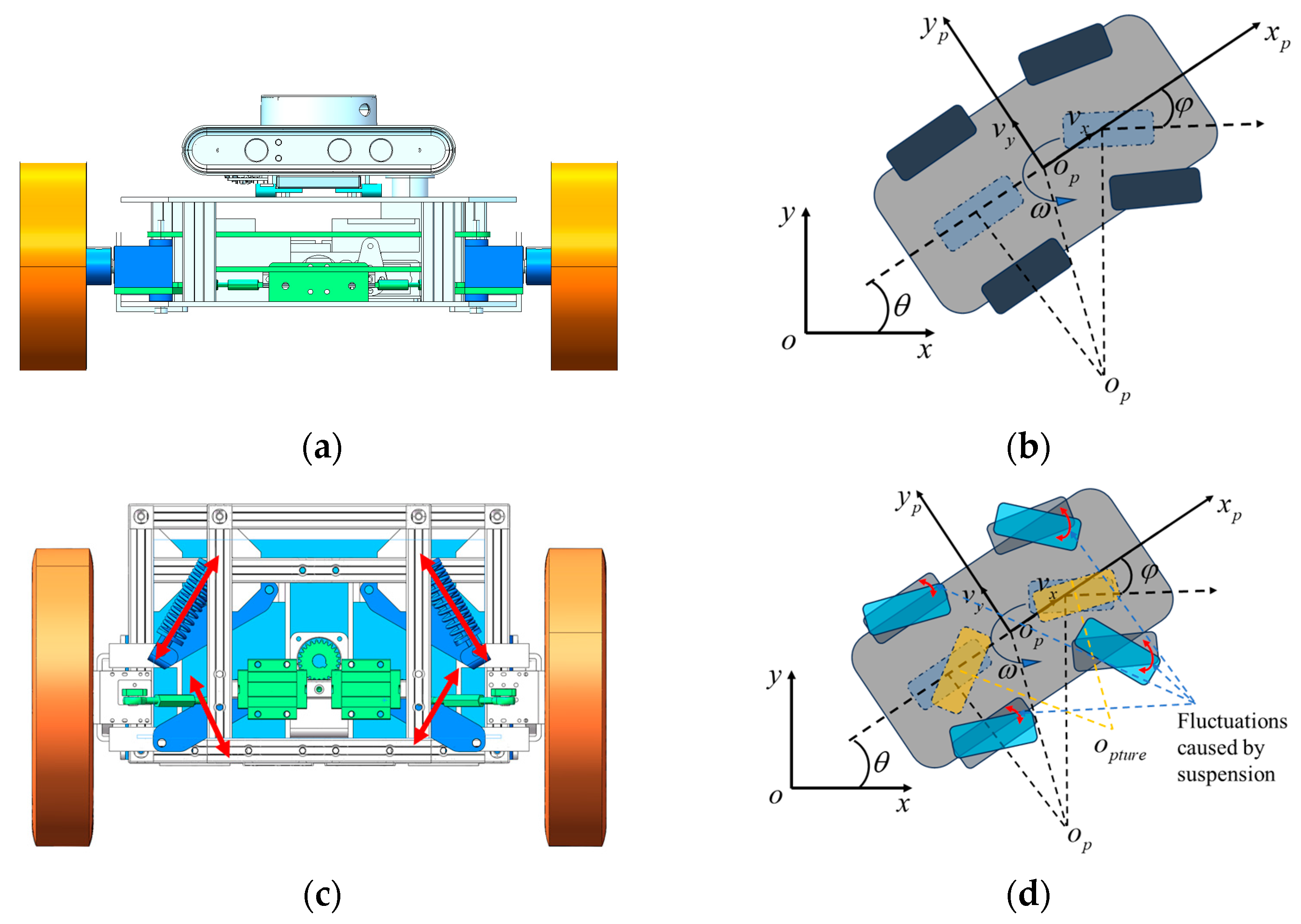
3. Accurate Fractional-Order-Based Kinematic Modeling of CLMR

As illustrated in Figure 1c,d, the CLMRs can dampen the vibration and improve the ability to cross the ditch by installing the suspension, which also leads to the unpredictability of the steering angle during the cornering process. Based on the parameters of the damping and hydraulic cylinders, the current steering angle constraints of the robot can be obtained, which provides the kinematic constraints for path acquisition. The path acquired in this way can satisfy the obstacle avoidance while improving the tracking accuracy. To simplify the calculation process, the steering wheel can be defined as a freewheel, i.e., the wheel can rotate freely around the axle. In the calculation process, a uniform local coordinate system is defined x p o p y p , with the robot center point as the origin of the local coordinate system and the direction perpendicular to the front of the vehicle as the x-axis. Then, the velocity of the virtual wheel in the global coordinate system is defined as:
[ v x p v y p ] = [ ( x m sin θ y m cos θ ) ω + v o x g ( x m cos θ y m sin θ ) ω + v o y g ]
where, v x p and v y p are the velocities of the virtual wheel in the global coordinate system in the x and y directions, respectively, x m and y m denote the coordinates of the virtual wheel in the local coordinate system in the x and y directions, respectively, and v o x g and v o y g are the velocity of the origin of the local coordinate system in the global coordinate system. Further, the acceleration expression can be obtained as:
[ v ˙ x p v ˙ y p ] = [ ( x m cos θ + y m sin θ ) ω 2 + ( x m sin θ y m cos θ ) ω ˙ + v ˙ o x g ( x m sin θ y m cos θ ) ω 2 + ( x m cos θ y m sin θ ) ω ˙ + v ˙ o y g ]
According to [37], it can be known that changes in the steering angle of the wheel system can cause dynamic torque distribution. In non-rigid suspension structures, torque fluctuation can cause wheel system displacement. From the torque distribution law, the deformation of the suspension near the inner side of the arc is greater than that on the outer side of the arc, resulting in a change of angle constraint. Fortunately, onboard sensors can accurately capture the current state information during the CLMR’s movement, allowing real-time constraint information to be calculated. Therefore, the variation of the virtual wheel direction angle ϕ c for the CLMR’s movement is calculated as:
ϕ c = ϕ m θ ϕ m = arctan ( x c m y c m )
Assuming that the posterior axis is fixed and parallel to the y-axis of the defined local coordinate system, there is no change in the point of the posterior axis. Consider that the velocity relation can be represented as:
v 2 = v x p 2 + v y p 2
therefore, it can be concluded that:
x v ω = v x p sin θ v y p cos θ
This leads to a general equation for the relationship between the CLMR’s attitude angle, velocity, and position, and a general constraint equation for the first-order derivatives. The relationship between the effects of velocity, attitude, and steering angle on path planning should be further clarified considering that the robot moves along a curve at different velocities. The running path (the planned path is obtained in the following section) is defined as:
y = f ( x )
Next, the slopes at the virtual wheels are calculated and the offset of the wheel system is taken into account. Conventional equations of kinematics do not correctly express the correctness of the system’s kinematic process, and fractional-order models offer the possibility of accurate system modelling. Therefore, we derive the trajectory equations and bring them into the above equation to obtain the following:
D ρ θ = 1 x v ( sin θ f ( x ) ) D α ( x )
where α and ρ are predefined fractional-order operators.
The steering angle of the CLMR imposes a constraint on the maximum curvature of the planned path, considering the dynamic characteristics of the CLMR’s kinematics. However, directly calculating the curvature constraints proves challenging. From Equation (8), ϕ m can be obtained from onboard sensors. Therefore, calculating the real-time rate of θ becomes the key to the solution. By combining Equations (11) and (12) we have the following:
D ρ θ D α ( x ) = ( sin θ D 1 α ( x ) f ( x ) cos θ ) x
and bringing Equation (7) into Equation (8), the corner constraint can be obtained as:
φ m a x = arctan ( ( x m cos θ y m sin θ ) ( sin θ D 1 α ( x ) f ( x ) cos θ ) x + f ( x ) ( x m sin θ y m cos θ ) ( sin θ D 1 α ( x ) f ( x ) cos θ ) x + 1 ) θ
Considering the fluctuation of suspension in different environments, fractional-order-based kinematic modelling provides precise and dynamic angle constraints. This improves the success rate of path planning for a CLMR in narrow and difficult-to-pass scenarios.
From Figure 1, the adjustment of the angular constraints mainly relies on the suspension adjustment of the wheel system in two degrees of freedom. However, through the change of the wheel system structure, the maximum constraint angle is also changed. At this point, the circular extension of the steering is not on the rear wheel system, which is of greater relevance to the planning of the path considering the mapping of the direction angle to the path. From Equation (8), it can be seen that the wheel system angle constraint varies with the change of the wheel system angle of rotation and the initial calibration position. For computational convenience, this paper focuses on the summation constraints of the virtual wheel system to improve computational and planning efficiency. With the calculation of the maximum constraint angle and the acquisition of the current steering angle from the sensing module, we can calculate the change in the maximum constraint angle.

4. Improved ACO Based Path Planning Using Fractional-Order Model

The traditional ACO usually uses the path length as the heuristic function term when solving the path planning problem; however, the environment faced during robot operation is more complex. Path planning, as a key module of mobile robot operation, plays a vital role in the safety and smoothness of robot operation. The pseudocode of the proposed ACO method is shown in Algorithm 1. In the algorithm, lines 1 to 3 are the initialization phase of the algorithm, which completes the initialization of the weight factors and pheromones. Lines 4 to 20 are the iterative part of the algorithm. Specifically, line 6 gives the initial position of the ant colony. Lines 8 to 16 are the ant colony search under the current iteration cycle, and the next moment position of the ant is obtained by transferring the probability model, recording the status of the ant colony, and determining the relationship with the target point. After the completion of the current iteration loop, the pheromone values τ i j ( t + 1 ) and path optimums Lk for the scenario are updated. In Line 21, the optimal values for each loop are compared and the optimal path Ln is selected.
Algorithm 1 The pseudocode of the improved ACO.
1/*Initialization*/
2Initialize the parameters, including λ 1 λ 2 φ 1 L t r ε η β 1 β 2 β 3
3Calculate initialize pheromone matrix τ i j ( 0 )
4/*main Loop*/
5While iteration number n does not arrive at the target N max  do:
6 Place all ants at the start point;
7  /*inner loop*/
8  For k = 1 to K do
9   Calculate the p i j k ( t ) using Formula (25) and confirm the next node
10   If Ant k reach the target point do
11    Goto step 15
12   Else
13    Goto step 9
14   End if
15   Select the optimal ant path for this round according to Equation (15)
16   End for
17 Update the τ i j ( t + 1 ) by Formulas (23)–(25)
18n = n + 1, k = 0
19 Select the optimal path Ln
20End while
21Return final optimal path Lk
To obtain a safe and feasible path, the safety, smoothness, and path distance of the path need to be considered comprehensively, so the improved multi-factor heuristic function is as follows:
J = φ 1 { λ 1 ω + λ 2 ( D + 1 d ) }
where J is the path planning heuristic function, φ 1 refers to the heuristic function that ensures the safe operation of the CLMR, λ 1 and λ 2 denote the weighting factors, respectively, ω i j ( k ) refers to the curvature smoothing factor, D ( k ) is the modified path heuristic function, and d ( k ) implies the standard path heuristic function, which is required by the planning method to obtain the minimum value of the cost function.

4.1. Factorization of the Cost Function with Fractional-Order Model

4.1.1. Safety Functions with Local Region Preprocessing

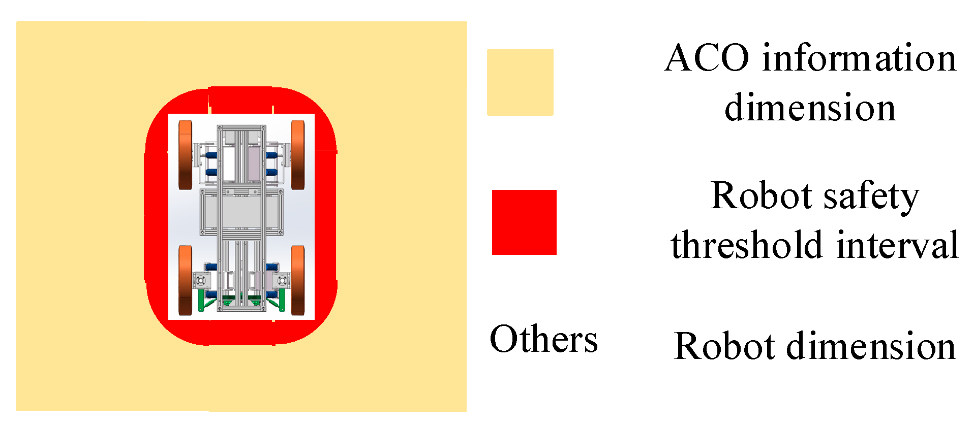
The operational safety of the mobile robot is the first factor to be considered for path planning. As shown in Figure 2, considering the existence of tracking errors, the planning module needs to leave enough redundant space. To facilitate the process, a common approach is to uniformly inflate the static map with the CLMR’s radius; however, in large-scale or highly dynamic scenarios, the optimal or relatively optimal paths are difficult to obtain and the length of the planned paths increases dramatically. Treating robots as a fixed matrix reduces the passability of a CLMR and leads to lower search efficiency. For this reason, this paper proposes a safety factor function based on ACO storage information, defined as follows:
φ i j 1 ( k ) = { 1 , L t r × S ( i , j ) i m d i l a t e ( M A × B ( i , j ) , L t r × S ( i , j ) ) L p i x × m o d ( D i r ( i , j ) , 2 ) = = 0 I n f ; I n f , O t h e r s
where
S ( i , j ) = R C × D × f ( θ )
where L t r is the safety threshold constant, S ( i , j ) denotes the intermediate function, i m d i l a t e ( ) refers to the map expansion function, M A × B ( i , j ) implies the map information stored by the ACO in the map information, A × B is expressed as the information dimension matrix, L p i x denotes the length of the map pixel point, m o d ( ) refers to the residual function, D i r ( i , j ) is the searching direction raster labelling, R C × D stands for the CLMR’s matrix under the CLMR’s coordinate system, C × D denotes the robot’s matrix dimensions, f ( θ ) is the coordinate system transfer matrix, and θ refers to the robot direction angle in global coordinates.

4.1.2. Smoothing Function Based on Dynamic Angle Constraints

The ACO iterates towards the final heuristic function during the planning process, while the smoothness and feasibility of the paths are not given much attention. However, the angle constraints of the robot impose new requirements on the planning of paths, while excessive corners reduce the feasibility of paths. Improving the smoothness of the path and eliminating excessive corners will help reduce the travelling time and improve the smoothness of the path. To address these issues, considering the dynamic characteristics of the dynamic angle constraints in fractional-order-based kinematic modelling, a dynamic smoothing factor is introduced to reduce the integrated angle probability and improve the comprehensive performance of the algorithm, and the corner smoothing function is:
ω i j ( k ) = { ε G ( i , j ) φ i j ( N max N k ) φ c N k φ i j φ c I n f φ i j > φ c
where φ c denotes the computed wheel system corner constraint, φ i j is the planning corner at point i to point j , ε denotes the path angle adjustment factor, G ( i , j ) represents the robot straight travelling function, N max stands for the maximum number of iterations, and N k 
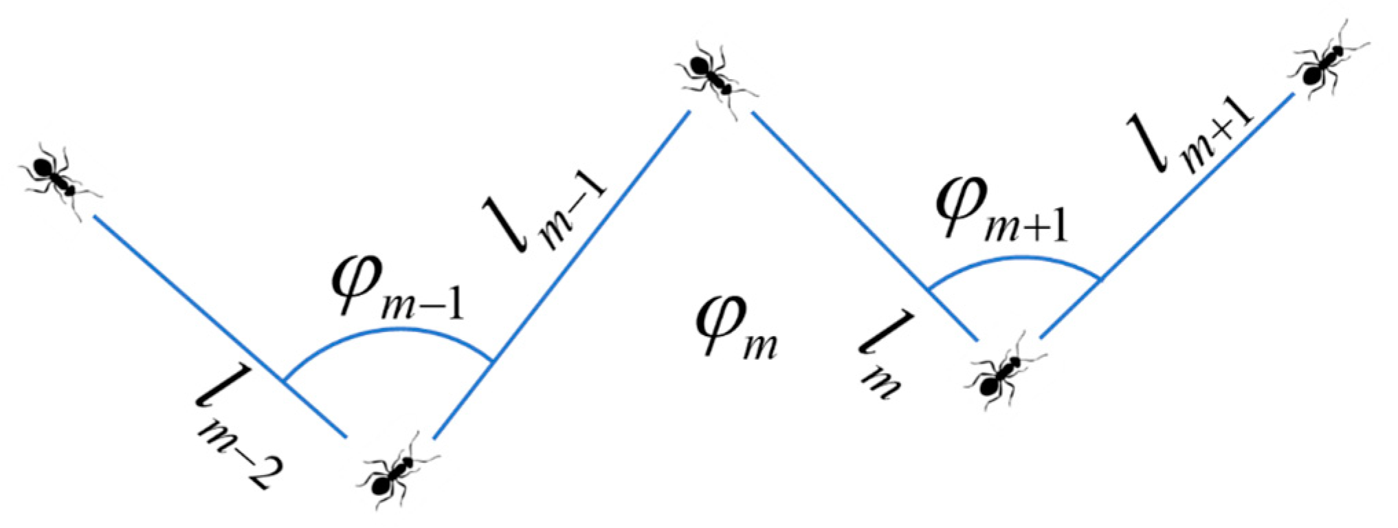
refers to the current number of iterations. Further, as shown in Figure 3, the robot straight line function is expressed as:
G ( i , j ) = { φ m 1 ( l m 2 + l m 1 ) + φ m ( l m 1 + l m ) + φ m + 1 ( l m + l m + 1 ) 2 ( l m 2 + l m 1 + l m + l m + 1 ) m 4 1 m < 4
where l m 2 , l m 1 , l m and l m + 1 are the four consecutive trajectories planned by the colony at the current point, and φ m 1 φ m and φ m + 1 represent the three consecutive corners consisting of these four trajectories.
The feasibility of the path is improved by the smoothing function with angle constraints. In the function, the smoothing factor of the angle is added to ensure the smoothness of the planned path, which is more favorable to the operation of the CLMR.

4.1.3. Path Functions by Adding Adjusting Factor

In actual operation, the length of the path is still an important factor to be considered, which is closely related to the CLMR’s work efficiency and energy utilization. For the traditional ACO, at the beginning of the iteration, the very small distance difference easily causes search confusion. At the late stage of convergence, there is a certain probability of falling into a local minimum. For this reason, we need to amplify the very small factor of fluctuation in the early stage in the distance factor to accelerate the convergence speed. In the later stages of iteration, we need to reduce the influence brought by the path, so that the path obtained is comprehensively optimal. The modified path factor function is:
D i j ( k ) = { η ( L ( m a x ( P i j , P G o a l ) ) d ( P i j , P G o a l ) ) L p i x + L ( m a x ( P i j , P G o a l ) ) L ( m i n ( P i j , P G o a l ) ) ( N max N k ) N k
where η is the path coefficient, L ( m a x ( P i j , P G o a l ) ) denotes the longest path from the current point P i j to the target point P G o a l planned by the ACO, L ( m i n ( P i j , P G o a l ) ) denotes the shortest path from the current point P i j to the target point P G o a l , and d ( P i j , P G o a l ) refers to the Euclidean distance from the current point P i j to the target point P G o a l .

4.2. Adaptive Pheromone Update Rules

Traditional ACO algorithms are usually set to a constant C in the initial stage, which leads to a blind search mainly relying on the heuristic function at the initial stage, and it is very easily falls into a local minimum in large scene maps. To solve this problem and improve the search efficiency, the initial pheromone is redistributed in the initial stage of the map with the help of the convergence method of the initial A* algorithm to speed up the subsequent path replanning in large scenes. The initial pheromone is recorded as:
τ i j ( 0 ) = { n c , j l p c , j o t h e r w i s e
In the actual operation of the CLMR, path planning is influenced by multiple factors, and the goal is to find an optimal path that considers all of these conditions collectively. Currently, efforts are focused on improving the amount of pheromone changes at different points along the path. The specific follow-up rules are as follows:
τ i j ( t + 1 ) = ( 1 ζ ( t ) ) τ i j ( t ) + τ i j ( t )
τ i j ( t ) = { κ 1 P h W + κ 2 P h L A , ( i , j ) a l l o w e d 0 , o t h e r s
where ζ ( t ) is the dynamic volatilization factor of pheromone, τ i j ( t + 1 ) denotes the pheromone matrix at the current moment, P h represents the pheromone concentration, κ 1 and κ 2 refer to the conditioning factors, W implies the mean squared deviation value of the walking angle, and L A denotes the cumulative path length from the starting point to the target point.
The iterative values of τ i j ( t ) are also dynamically adjusted through the changes of angle W and distance values L A . By setting the magnitude of the values of weight coefficients κ 1 and κ 2 , the acquisition of effective paths that are more compatible with the scene is facilitated.
The dynamic pheromone volatilization factor is designed as:
ζ ( t ) = { a N m a x N k ζ ( t 1 ) , t 0 , ( 0 < a < 1 ) ζ i n i t , t 0
where a and ζ i n i t are self-defined constants, and ζ ( t ) can be adjusted adaptively with the search.
From Equation (24), it can be seen that the pheromone volatilization function ζ ( t ) reaches the maximum value in the pre-search period of the ACO which is in the period of the fastest change of the pheromone volatilization value. This increases the uncertainty factor in the early stage of the algorithm during the optimization process, which is more conducive to obtaining the globally optimal feasible solution. As the number of iterations increases, the pheromone volatility function ζ ( t ) tends to stabilize, and the local search process is more frequent, which helps to improve the quality of the path. Therefore, the iterative process accomplishes the adaptive regulation of pheromone concentration, which facilitates the realization of rapid path planning and optimization.

4.3. Fractional-Order Transfer Probability Rules

To obtain the feasible path faster and ensure the quality of the path, this paper improves the transfer probability of the algorithm. It makes the target probability increase the angle factor and distance factor. It is expected to obtain the shortest path under the premise of ensuring a smooth path. The improved state transfer probability is:
p i j k ( t ) = { [ τ i j ( t ) ] β 1 [ D α 1 R i j ( t ) ] β 2 [ D α 2 Q i j ( t ) ] β 3 S a l l o w e d [ τ i s ( t ) ] β 1 [ D α 1 R i s ( t ) ] β 2 [ D α 2 Q i s ( t ) ] β 3 , 0
where β 1 , β 2 , and β 3 denote the heuristic term factor, respectively, and R i j ( t ) and Q i j ( t ) are defined as follows:
D α 1 R i j ( t ) = D α 1 ω i j ( t )
D α 2 Q i j ( t ) = D α 1 ( D i j ( t ) + d i j ( t ) )
The fractional reciprocal of the angle factor and the distance factor is calculated to improve the sensitivity of the transition probability to its change, to ensure the timeliness of the path change and to improve the passability of the path.
A fractional-order state-transfer model can more accurately adjust the exploration probability of ant colonies in unexplored areas, which is beneficial for ant colony algorithms to jump out of the current local optimal solution and search for the global optimal solution with a greater probability, thereby improving the success rate of the search in large-scale scenarios. At the same time, due to the high dependence of the pheromone concentration on the optimal path, the modification of the transfer model increases the search breadth and the search probability of the optimal path, avoiding the acquisition of the optimal path, accelerating the search process around the optimal path, and thus improving the convergence speed.

5. Experimental Validations

5.1. Experimental Implementation

The narrow and large-size experimental scenes and self-developed CLMRs are shown in Figure 4. The CLMR consists of an industrial computer (Intel(R) Core (TM) i7-6500U CPU @2.50 GHz, 8 GB of RAM, 64-bit operating system), LiDARs, motor encoders, and some related sensors, such as an ultrasonic transducer and IMU. More specifically, with an impressive range of 150 m and a scanning rate of 10 Hz, the Velodyne VLP-16 LiDAR provides the CLMR with a broad field of view, which guarantees that the CLMR has enough field of view to ensure safety and real-time mapping and path planning. As illustrated in Figure 4a, to improve the stability and passability of the CLMRs in complex environments, the drive and steering mechanisms are fitted with suspensions. As we can see from Figure 4b–d, the entire neighborhood is quite expansive, covering an area of sixteen thousand square meters. However, the alleyways within the neighborhood are remarkably narrow. These tight spaces are often filled with temporarily parked cars and bustling pedestrians, which severely limits the available space for CLMRs to navigate through. In particular, shown in Figure 4b, to obtain more detailed and practical paths, we chose a grid map with a resolution of 0.2 m, making the map size 800 × 500, which is a great challenge for the path planning algorithm.

5.2. Experimental Results and Discussions

In the experiment, it is necessary to obtain real-time vehicle positioning data and wheel steering angle data. Real-time recording and storage of experimental data was performed on the PC. The planning, calculation, allocation, and execution process are as follows: The current data are processed by the data processing unit and returned to MATLAB. Then, MATLAB is used to complete the calculation of the planning algorithm. Finally, the path instructions generated by the planning are sent to the control unit, completing the current path planning process. The initial state of the considered robot is the same, all parameters are optimally adjusted, and experiments are conducted under the same operating conditions. In the process of parameter tuning, parameter stabilization is achieved through the use of a nature-inspired optimization algorithm called Artificial Bee Colony [38], which reduces the sensitivity of the parameters to the environment and also ensures the fairness of the algorithm comparison process. The values of the parameters obtained are as follows: λ 1 = 0.6 , λ 2 = 0.2 , ε = 0.1 , N max = 50 , η = 1.1 , κ 1 = 0.8 , κ 2 = 0.2 , and a = 0.4 . The superiority of the proposed fractional-order ACO (FACO) is verified by comparing it with the traditional A*, improved A* (IA) [26], ACO [28], improved ACO combined with path fitting (ACOF) [39], Genetic Algorithm (GA) [29], and the GA method combined with A* (AGA). We used different algorithms to run each of them ten times in large-scale narrow scenes. To better validate the effectiveness and advantages of the proposed method, we drew on the comparative methods in literature [40] and selected common path lengths, times, and success rates of trajectory planning (including planning failures and collisions with obstacles) to accurately describe the process of path planning. The comparison results are shown in Table 1, and the experimental results of the planned path are shown in Figure 5, Figure 6, Figure 7, Figure 8, Figure 9, Figure 10 and Figure 11.
From Table 1, it can be seen that the A* algorithm takes the longest time, which is because the A* algorithm completes the traversal of the surrounding space before finding the target point, and due to the high-precision attribute of the map, more and more computational resources are consumed and the computational speed decreases dramatically in the planning process. In the improved A* method, the search direction is guided to improve the planning efficiency, but to ensure the success rate of path planning, the efficiency improvement for a large-space search is not obvious. GA has excellent performance in the field of optimization, and in the planning process GA achieves random sampling in the space by repeated cross-compilation, which greatly reduces the planning time, and by combining it with the A* algorithm, there is an increase in the planning time, but there is an increase in the stability of the path. The ACO-based planning algorithm demonstrates reduced dependency on parameters in path planning. However, employing pure ACO preprocessing alone increases the time required. By combining the ACO algorithm with A*, the overall time decreases further. In the proposed method, the additional search burden caused by the large space is mitigated through local space weighting in the ACO search. This reduction in computational burden leads to improved planning efficiency. Experimental results show a significant enhancement in efficiency with the proposed method, achieving improvements of 92.56%, 57.84%, and 81.82% compared to traditional A*, GA, and ACO methods, respectively. These improvements have great significance for real-world scenarios.
In terms of path length, the A* method shows a greater advantage due to the objective of the method to obtain shorter paths, and with the increase in constraints, the paths of the improved methods based on A*, GA, and ACO all increase to varying degrees. Further analysis shows that GA shows significant non-randomness of paths due to the random sampling in space and the path length appears to increase to a greater extent, whereas the ACO algorithm shows better stability of paths due to having an advanced spatial search and shorter path lengths. The proposed method needs to meet the actual operational requirements and the dynamic constraints make the planned paths increase, but the length of the planned paths decreases by 0.63%, 0.40%, and 2.10% compared to the improved methods of A*, GA, and ACO, respectively. When comparing the various path planning, all of them show better results in terms of path length. However, the proposed method is more advantageous under the constraints.
In Table 2, the smoothness indicator is given, which reflects the proportion of different steering angles between path points in path planning. It has been proven that a smoother trajectory is achieved when there is a lower proportion of large steering angles. However, optimization-based planning algorithms, such as GA, AGA, ACO, and ACOF, often prioritize a single performance improvement, resulting in a path consisting of a relatively simple finite set of points. For example, the GA algorithm represents the path using only five coordinate points, and the proportion of large steering angles reaches 66.67%. Consequently, these optimization algorithms introduce numerous angle mutation points, making it challenging to ensure a smooth path. Moreover, traditional path planning methods like A* and IA struggle to incorporate dynamic angle constraints at corners, leading to scattered abrupt changes in the path. Although smoothing the obtained path can prevent the occurrence of mutation points, it may also result in high spatial requirements after the smoothing process. To address these challenges, we propose a novel path planning algorithm that fully leverages the constraint characteristics of angles. This algorithm performs real-time smoothing during the planning phase, avoiding abrupt changes in the path’s angle, the proportion of small steering angles exceeds 99%, which means that the proposed method is essentially free of steering mutations. As a result, it offers significant benefits for planning in narrow spaces while still considering angle constraints.
According to the results of path planning from Figure 5, Figure 6, Figure 7, Figure 8, Figure 9, Figure 10 and Figure 11, it is evident that both the A* algorithm and its improved version can produce relatively smooth paths. However, it is noticeable that the paths tend to excessively prioritize shorter routes at corner nodes and articulation points. This pursuit of shorter paths increases operational risks and reduces feasibility. In the GA method, random sampling points introduce a certain possibility of encountering large corners, resulting in longer paths, and placing higher demands on the CLMR’s maneuverability. To address this issue, the combination of A* and GA methods improves the path’s smoothness and provides guidance. Nonetheless, the presence of more corners and narrow areas in the path poses greater challenges for the robot’s capabilities and model. In the planning of ACO, it follows the pursuit of the shortest path when the path shows better smoothness, but the passage is not considered in the method. Given this, after combining with A*, the smoothing of the path is proposed, and here the B-spline is used for processing because the smoothing of the path is usually accompanied by a change in the path points, and it can be seen from the figure that, due to the space being relatively small, the path status quo is changed, and a larger set of points appeared to be in contact with the obstacles, which poses a greater threat to the operational safety, making it difficult for the traditional path smoothing to be sufficient. In the proposed method, a transfer model of fractional-order is established by building a fractional-order model with constraints in the method, which improves the path smoothing, avoids the path changes brought about by the additional path smoothing, and improves the path safety, while the obtained smoothed paths ensures the path feasibility. At the same time, we can see that the paths of ACOF are corrected to increase smoothness, but in a narrow space, and this late correction makes it easy for the planned paths to run into obstacles, resulting in a drastic decrease in their success rate. The proposed method, on the other hand, maintains smoothness and at the same time has a high success rate, which proves the excellent performance of the planning method based on the fractional-order model.
Figure 12 provides the mean and current lowest values of the objective function for various optimization algorithms: GA—both Mean GA (MGA) and Current Lowest GA (CLGA), AGA—both Mean AGA (MAGA) and Current Lowest AGA (CLAGA), ACO—both Mean ACO (MACO) and Current Lowest ACO (CLACO), ACOF—both Mean ACOF (MACOF) and Current Lowest ACOF (CLACOF), and FACO—both Mean FACO (MFACO) and Current Lowest FACO (CLFACO). GA is characterized by fast convergence in the initial stage; however, with the depth of the iteration, the GA is more likely to fall into premature maturity. In contrast to the ACO calculation, the method is more dependent on the initial value, and the convergence is slower in the early stage; however, with the help of the method’s adaptation to nonlinear and complex problems it has an advantage in dealing with the local optimal solution. To improve the search efficiency, the traversal based on the A* method is used in this paper: AGA, ACOF, and FACO. This shows great advantages in the fast convergence of the mean value and the optimization of the minimum value. In the iterative search for the minimum value, AGA achieves faster convergence, while ACOF and FACO can still jump out of the current local optimality conditions and further search for the global optimal solution. Therefore, the proposed method has a great advantage in realizing the optimal value of the cost function in this paper.

6. Conclusions and Outlook

This paper presents a novel ACO approach for the path planning of CLMRs with suspension in narrow and large-scale environments, which combines fractional-order enhanced path planning with an improved ACO algorithm to achieve smooth and efficient paths. To improve the accuracy of the kinematic model construction for CLMRs with suspension, a precise fractional-order-based kinematic modeling method is introduced. This method takes into account the dynamic adjustment of angle constraints, resulting in a more accurate representation of the CLMR’s motion. Furthermore, the path planning algorithm is further enhanced by incorporating fractional-order transfer-probability modelling into the ACO framework. This extension effectively addresses the challenges associated with local optima and lack of smoothness in narrow spaces. Additionally, it improves the search speed in large-scale scenes, ensuring more efficient and optimized path planning.
It is worth noting that the proposed method adopts a fixed fractional order although it is more accurate and flexible than the integer order, but the exact value of the fractional order is still a challenge. In future work, we will introduce sensor observation, further implement variable fractional order to improve the accuracy of model construction and explore the potential application of fractional-order models in other path planning methods. In addition, we will subsequently refine the path planning methods and further investigate local planning algorithms based on the existing global path planning to cope with highly dynamic scenarios.

Author Contributions

Conceptualization, L.L. and L.J. (Liquan Jiang); methodology, L.L. and L.J. (Liquan Jiang); software, L.J. (Liyu Jiang) and L.J. (Liquan Jiang); validation, L.J. (Liquan Jiang); formal analysis, W.T.; investigation, L.L. and W.T.; resources, L.J. (Liquan Jiang)); data curation, W.T.; writing—original draft preparation, L.L., R.H. and L.J. (Liquan Jiang); writing—review and editing, L.J. (Liquan Jiang); visualization, L.J. (Liyu Jiang) and R.H.; supervision, L.J. (Liquan Jiang)); project administration, L.J. (Liquan Jiang); funding acquisition, L.J. (Liquan Jiang). All authors have read and agreed to the published version of the manuscript.

Funding

This research was funded in part by the Hubei Provincial Engineering Research Center for Intelligent Textile and Fashion (Wuhan Textile University) under Grant no. 2023HBITF03, in part by State Key Laboratory of New Textile Materials and Advanced Processing Technologies no. FZ20230023, in part by Hubei Key Laboratory of Digital Textile Equipment no. DTL2023023 and in part by Fund of National Engineering Research Center for Water Transport Safety under Grant no. A202303.

Data Availability Statement

The data presented in this study may be available on request from the corresponding author.

Conflicts of Interest

The authors declare no conflicts of interest.

References

  1. Liu, L.; Wang, X.; Yang, X.; Liu, H.; Li, J.; Wang, P. Path planning techniques for mobile robots: Review and prospect. Expert Syst. Appl. 2023, 227, 120254. [Google Scholar] [CrossRef]
  2. Meng, J.; Wang, S.; Xie, Y.; Li, G.; Zhang, X.; Jiang, L.; Liu, C. A safe and efficient LIDAR-based navigation system for 4WS4WD mobile manipulators in manufacturing plants. Meas. Sci. Technol. 2021, 32, 045203. [Google Scholar] [CrossRef]
  3. Wu, L.; Huang, X.; Cui, J.; Liu, C.; Xiao, W. Modified adaptive ant colony optimization algorithm and its application for solving path planning of mobile robot. Expert Syst. Appl. 2023, 215, 119410. [Google Scholar] [CrossRef]
  4. Li, G.; Liu, C.; Wu, L.; Xiao, W. A mixing algorithm of ACO and ABC for solving path planning of mobile robot. Appl. Soft. Comput. 2023, 148, 110868. [Google Scholar] [CrossRef]
  5. Ben-Asher, J.Z.; Rimon, E.D. Time optimal trajectories for a car-like mobile robot. IEEE Trans. Robot. 2021, 38, 421–432. [Google Scholar] [CrossRef]
  6. Shui, Y.; Zhao, T.; Dian, S.; Hu, Y.; Guo, R.; Li, S. Data-driven generalized predictive control for car-like mobile robots using interval type-2 T-S fuzzy neural network. Asian J. Control 2022, 24, 1391–1405. [Google Scholar] [CrossRef]
  7. Theunissen, J.; Tota, A.; Gruber, P.; Dhaens, M.; Sorniotti, A. Preview-based techniques for vehicle suspension control: A state-of-the-art review. Annu. Rev. Control 2021, 51, 206–235. [Google Scholar] [CrossRef]
  8. Meng, J.; Wang, S.; Jiang, L.; Hu, Z.; Xie, Y. Accurate and Efficient Self-localization of AGV Relying on Trusted Area Information in Dynamic Industrial Scene. IEEE Trans. Veh. Technol. 2023, 72, 7148–7159. [Google Scholar] [CrossRef]
  9. Qie, T.; Wang, W.; Yang, C.; Li, Y.; Liu, W.; Xiang, C. A path planning algorithm for autonomous flying vehicles in cross-country environments with a novel TF-RRT* method. Green Energy Intell. Trans. 2022, 1, 100026. [Google Scholar] [CrossRef]
  10. Miao, C.; Chen, G.; Yan, C.; Wu, Y. Path planning optimization of indoor mobile robot based on adaptive ant colony algorithm. Comput. Ind. Eng. 2021, 156, 107230. [Google Scholar] [CrossRef]
  11. Mac, T.T.; Copot, C.; Tran, D.T.; De Keyser, R. Heuristic approaches in robot path planning: A survey. Robot. Auton. Syst. 2016, 86, 13–28. [Google Scholar] [CrossRef]
  12. Song, B.; Wang, Z.; Zou, L. An improved PSO algorithm for smooth path planning of mobile robots using continuous high-degree Bezier curve. Appl. Soft. Comput. 2021, 100, 106960. [Google Scholar] [CrossRef]
  13. Sang, H.; You, Y.; Sun, X.; Zhou, Y.; Liu, F. The hybrid path planning algorithm based on improved A* and artificial potential field for unmanned surface vehicle formations. Ocean Eng. 2021, 223, 108709. [Google Scholar] [CrossRef]
  14. Nassef, A.M.; Abdelkareem, M.A.; Maghrabie, H.M.; Baroutaji, A. Metaheuristic-Based Algorithms for Optimizing Fractional-Order Controllers—A Recent, Systematic, and Comprehensive Review. Fractal Fract. 2023, 7, 553. [Google Scholar] [CrossRef]
  15. Jiang, L.; Wang, S.; Xie, Y.; Xie, S.; Zheng, S.; Meng, J.; Ding, H. Decoupled fractional supertwisting stabilization of interconnected mobile robot under harsh terrain conditions. IEEE Trans. Ind. Electron. 2021, 69, 8178–8189. [Google Scholar] [CrossRef]
  16. Jiang, L.; Wang, S.; Xie, Y.; Xie, S.Q.; Zheng, S.; Meng, J. Fractional robust finite time control of four-wheel-steering mobile robots subject to serious time-varying perturbations. Mech. Mach. Theory 2022, 169, 104634. [Google Scholar] [CrossRef]
  17. Xie, Y.; Zhang, X.; Meng, W.; Zheng, S.; Jiang, L.; Meng, J.; Wang, S. Coupled fractional-order sliding mode control and obstacle avoidance of a four-wheeled steerable mobile robot. ISA Trans. 2021, 108, 282–294. [Google Scholar] [CrossRef] [PubMed]
  18. Patnaik, S.; Hollkamp, J.P.; Semperlotti, F. Applications of variable-order fractional operators: A review. Proc. R. Soc. London Ser. A-Math. Phys. Eng. Sci. 2020, 476, 20190498. [Google Scholar] [CrossRef]
  19. Zhao, C.; Dai, L.; Huang, Y. Fractional-order Sequential Minimal Optimization Classification Method. Fractal Fract. 2023, 7, 637. [Google Scholar] [CrossRef]
  20. Muresan, C.I.; Birs, I.; Ionescu, C.; Dulf, E.H.; De Keyser, R. A review of recent developments in autotuning methods for fractional-order controllers. Fractal Fract. 2022, 6, 37. [Google Scholar] [CrossRef]
  21. Tzafestas, S.G. Mobile robot control and navigation: A global overview. J. Intell. Robot. Syst. 2018, 91, 35–58. [Google Scholar] [CrossRef]
  22. Jiang, H.; Xu, G.; Zeng, W.; Gao, F. Design and kinematic modeling of a passively-actively transformable mobile robot. Mech. Mach. Theory 2019, 142, 103591. [Google Scholar] [CrossRef]
  23. Mohammadpour, M.; Kelouwani, S.; Gaudreau, M.A.; Zeghmi, L.; Amamou, A.; Bahmanabadi, H.; Graba, M. Energy-efficient motion planning of an autonomous forklift using deep neural networks and kinetic model. Expert Syst. Appl. 2024, 237, 121623. [Google Scholar] [CrossRef]
  24. Song, B.; Wang, Z.; Zou, L.; Xu, L.; Alsaadi, F.E. A new approach to smooth global path planning of mobile robots with kinematic constraints. Int. J. Mach. Learn. Cybern. 2019, 10, 107–119. [Google Scholar] [CrossRef]
  25. Rubio, F.; Valero, F.; Llopis-Albert, C. A review of mobile robots: Concepts, methods, theoretical framework, and applications. Int. J. Adv. Robot. Syst. 2019, 16, 1729881419839596. [Google Scholar] [CrossRef]
  26. Niu, C.; Li, A.; Huang, X.; Li, W.; Xu, C. Research on Global Dynamic Path Planning Method Based on Improved A* Algorithm. Math. Probl. Eng. 2021, 2021, 1–13. [Google Scholar] [CrossRef]
  27. Wang, J.; Chi, W.; Li, C.; Wang, C.; Meng, M.Q.H. Neural RRT*: Learning-based optimal path planning. IEEE Trans. Autom. Sci. Eng. 2020, 17, 1748–1758. [Google Scholar] [CrossRef]
  28. Lyridis, D.V. An improved ant colony optimization algorithm for unmanned surface vehicle local path planning with multi-modality constraints. Ocean Eng. 2021, 241, 109890. [Google Scholar] [CrossRef]
  29. Nazarahari, M.; Khanmirza, E.; Doostie, S. Multi-objective multi-robot path planning in continuous environment using an enhanced genetic algorithm. Expert Syst. Appl. 2019, 115, 106–120. [Google Scholar] [CrossRef]
  30. Li, Y.; Zhao, J.; Chen, Z.; Xiong, G.; Liu, S. A robot path planning method based on improved genetic algorithm and improved dynamic window approach. Sustainability 2023, 15, 4656. [Google Scholar] [CrossRef]
  31. Aggarwal, S.; Kumar, N. Path planning techniques for unmanned aerial vehicles: A review, solutions, and challenges. Comput. Commun. 2020, 149, 270–299. [Google Scholar] [CrossRef]
  32. Khedr, A.M.; Al Aghbari, Z.; Khalifa, B.E. Fuzzy-based multi-layered clustering and ACO-based multiple mobile sinks path planning for optimal coverage in WSNs. IEEE Sens. J. 2022, 22, 7277–7287. [Google Scholar] [CrossRef]
  33. Liu, C.; Wu, L.; Xiao, W.; Li, G.; Xu, D.; Guo, J.; Li, W. An improved heuristic mechanism ant colony optimization algorithm for solving path planning. Knowl. Based Syst. 2023, 271, 110540. [Google Scholar] [CrossRef]
  34. Ajeil, F.H.; Ibraheem, I.K.; Azar, A.T.; Humaidi, A.J. Grid-based mobile robot path planning using aging-based ant colony optimization algorithm in static and dynamic environments. Sensors 2020, 20, 1880. [Google Scholar] [CrossRef] [PubMed]
  35. Ali, H.; Gong, D.; Wang, M.; Dai, X. Path planning of mobile robot with improved ant colony algorithm and MDP to produce smooth trajectory in grid-based environment. Front. Neurorobotics 2020, 14, 44. [Google Scholar] [CrossRef] [PubMed]
  36. Feng, K.; He, X.; Wang, M.; Chu, X.; Wang, D.; Yue, D. Path Optimization of Agricultural Robot Based on Immune Ant Colony: B-Spline Interpolation Algorithm. Math. Probl. Eng. 2022, 2022, 2585910. [Google Scholar] [CrossRef]
  37. Zhang, X.; Xie, Y.; Jiang, L.; Li, G.; Meng, J.; Huang, Y. Fault-tolerant dynamic control of a four-wheel redundantly-actuated mobile robot. IEEE Access 2019, 7, 157909–157921. [Google Scholar] [CrossRef]
  38. Kiran, M.S.; Hakli, H.; Gunduz, M.; Uguz, H. Artificial bee colony algorithm with variable search strategy for continuous optimization. Inf. Sci. 2015, 300, 140–157. [Google Scholar] [CrossRef]
  39. Abdulakareem, M.; Raheem, F.A. Development of path planning algorithm using probabilistic roadmap based on ant colony optimization. Engin. Techn. J. 2020, 38, 343–351. [Google Scholar] [CrossRef]
  40. Gao, W.; Tang, Q.; Ye, B.; Yang, Y.; Yao, J. An enhanced heuristic ant colony optimization for mobile robot path planning. Soft Comput. 2020, 24, 6139–6150. [Google Scholar] [CrossRef]
Figure 1. The kinematic model of CLMRs. (a) CLMR that does not consider suspension; (b) Traditional kinematic model that does not consider suspension; (c) CLMR that considers suspension; (d) Actual kinematic model that consider suspension.
Fractalfract 08 00157 g001
Figure 2. Planning Safety Thresholds of the CLMR.
Fractalfract 08 00157 g002
Figure 3. Planning Straight-line Constraints of the CLMR.
Fractalfract 08 00157 g003
Figure 4. Experimental scene and platform. (a) Self-developed CLMR; (b) Real-world scene; (c) Google map of the narrow and large-size scene; (d) Grid map of the narrow and large-size scene.
Fractalfract 08 00157 g004
Figure 5. Path planning result of A*.
Fractalfract 08 00157 g005
Figure 6. Path planning result of IA.
Fractalfract 08 00157 g006
Figure 7. Path planning result of GA.
Fractalfract 08 00157 g007
Figure 8. Path planning result of AGA.
Fractalfract 08 00157 g008
Figure 9. Path planning result of ACO.
Fractalfract 08 00157 g009
Figure 10. Path planning result of ACOF.
Fractalfract 08 00157 g010
Figure 11. Path planning result of FACO.
Fractalfract 08 00157 g011
Figure 12. Comparison of the objective function value.
Fractalfract 08 00157 g012
Table 1. Performance comparison of different path planning methods.
MethodsPath Length (m)Times (s)Success Rate (%)
A*91.60857.26100
IA93.57591.73100
GA101.24100.61100
AGA93.36123.67100
ACO89.20350.66100
ACOF94.97153.710
FACO92.9863.74100
Table 2. The proportion of different steering angles between path points.
Methods0–5°5–10°>10°
A*98.39%1.15%0.46%
IA96.77%2.30%0.93%
GA033.33%66.67%
AGA00100%
ACO33.33%066.67%
ACOF100%00
FACO99.4%0.6%0
Disclaimer/Publisher’s Note: The statements, opinions and data contained in all publications are solely those of the individual author(s) and contributor(s) and not of MDPI and/or the editor(s). MDPI and/or the editor(s) disclaim responsibility for any injury to people or property resulting from any ideas, methods, instructions or products referred to in the content.

