Article

Effect of Sweep on Axial Fan Noise Sources Using the Lattice Boltzmann Method

1
Department of Mechanical Engineering, Université de Sherbrooke, 2500 Boulevard de l’Université, Sherbrooke, QC J1K2R1, Canada
2
Department of Mechanical Engineering, École de Technologie Supérieure, 1100 rue Notre-Dame Ouest, Montréal, QC H3C1K3, Canada
3
Simulation and Reliability Metier, Valeo Thermal Systems, 78320 La Verrière, France
*
Author to whom correspondence should be addressed.
Int. J. Turbomach. Propuls. Power 2022, 7(4), 34; https://doi.org/10.3390/ijtpp7040034
Submission received: 23 August 2022 / Revised: 3 November 2022 / Accepted: 14 November 2022 / Published: 22 November 2022
(This article belongs to the Special Issue Fan Noise, Aerodynamics, Applications and Systems)

Abstract

:
The effect of blade sweep has been studied numerically with the Lattice Boltzmann Method on a family of low-speed free-vortex axial fans with sweeps of ±45°. Good overall aerodynamic agreement is first demonstrated on all fans at the design condition, particularly in the tip gap. The local larger wall-pressure fluctuations seen in the unswept and backward swept fans compared to the forward case are traced to the stronger tip vortices that remain in the rotational plane or even move upstream. These stronger and faster vortices interacting with the fan blades are then responsible for the larger noise levels observed in the acoustic spectra of these fans, and particularly for large subharmonic humps. Excellent agreement between experimental and numerical noise predictions is finally reported stressing the dominant tip noise.

Graphical Abstract

1. Introduction

Low-speed axial fans are widely used in many ventilation applications (automotive and train engine cooling, tunnel venting, electronic and electrical motor cooling, residential air conditioning systems). They contribute to the rising environmental noise pollution, which needs to be mitigated for all fan manufacturers in order to meet new regulations [1]. To reach such a goal, the cheapest noise control strategy is modifying the blade geometry itself. Blade skew for instance [2] has been shown to reduce fan noise, and several patents have already been filed around the noise benefits achieved by either forward or backward sweep. For low-speed rotating machines, sweep is the angle defined in the plane of rotation [3]. This is the definition used in the present work. Different behaviors and mitigation results have also been observed depending on the operating conditions. Moreover, noise predictions are still often based on empirical models and iterative, lengthy experimental investigations that do not allow a fine understanding of the aeroacoustic source mechanisms and a significant noise reduction. In fact, the origin of the noise reduction caused by sweep is still a matter of debate as stressed in [4,5], which makes it difficult to assess and quantify the noise reduction provided by sweep for each new fan design.
Yet, in recent years, new methods such as the Lattice Boltzmann method have emerged that can provide direct noise predictions in complex, realistic environments [5,6]. In the present study, the effect of sweep on fan noise is then tackled with an unsteady Lattice-Boltzmann solver, by mimicking as closely as possible the experiments run at the Friedrich-Alexander Universität (FAU) on a family of fans designed with different sweeps for the same operating condition [3,7,8,9,10]. Both aerodynamic and acoustic results are reported to shed a deeper insight into the aero-acoustic effect of sweep and how it can help mitigate fan noise.

2. Experimental Background

2.1. Configuration Description

The investigated axial fans of diameter D = 495 mm shown in Figure 1 have 9 blades made of NACA 4510 profiles. Different blade designs were considered [5]: we here focus on the S1-family designed with a free vortex. All fans have been designed for the same operating conditions: a flow rate of 1.4 m3/s (flow coefficient ϕ = 0.252), a total-to-static pressure difference of 150 Pa, at 1500 rpm. They are either unswept (US) or forward swept (FS) or backward swept (BS). The latter sweep is significant, ±45°. They have been tested in the FAU anechoic wind tunnel (Erlangen-Nürnberg, Germany) shown in Figure 2, which consists of a large anechoic room around which is wrapped a ducted fan and silencers. The fans are placed in a short duct with a bell-mouth attached to the downstream part of the plenum (Figure 2 (right)). The gap between the duct and the fan tip is 2.5 mm. For the above operating conditions, the blade-passing frequency (BPF) is 225 Hz.

2.2. Experimental Database

Overall flow performances have first been measured for all fans. The flow enters the test rig at the top in Figure 2a through a standardized inlet bell mouth to measure the volume flow rate. In order to provide homogeneous and low-turbulent inflow conditions for the test fan, a flow straightener is installed inside the test chamber. The total-to-static pressure difference is measured with a differential pressure transducer that is connected to pressure taps inside the test chamber and to an ambient pressure line outside the test chamber. All detailed velocity measurements were achieved with a laser Doppler anemometer in two planes 10 mm before and after the fans. The sound pressure levels were measured with seven 1/2 inch free-field Brüel & Kjær microphones (type 4189-L-001), placed on a semicircle at a radius of 1 m around the inlet bell mouth in a horizontal plane at the same height as the fan rotational axis (Figure 2b).
Figure 2. Sketch of anechoic test facility at FAU (a) and microphone arrangement (b) (adapted from [5]).
Ijtpp 07 00034 g002

3. Numerical Investigation

3.1. Numerical Setup

As shown in [7], the Lattice Boltzmann Method (LBM) is a very efficient direct computational aeroacoustic method for low speed fans installed in a complex environment such as described in Figure 2, and has therefore been selected in the present study. All simulations have been achieved with the commercial solver developed by 3DS, PowerFLOW version 5.5c [11,12,13,14,15]. For the present low-Mach number flow, the efficient D3Q19 discretization scheme is used. It has excellent dissipation and dispersion properties as shown by Marié for instance [16], providing not only a direct insight into the near-field acoustic sources in the fan but also in the acoustic propagation to the far field.
The computational domain includes most of the anechoic wind tunnel presented in Figure 2 (left), embedded in a large domain standing for the actual lab as shown in Figure 3. Additional large damping zones wrap around the domain seen in Figure 3, to prevent any reflection. The only simplification has consisted in limiting the outside duct to the final straight section and bend with deflector. Indeed, the flow becomes uniform with the splitter-type silencer in the straight duct. Note that the honeycomb flow straightener inside the plenum shown in Figure 2 (left) is accounted for in the simulation by an equivalent anisotropic porous medium. The computational domain is then discretized by cubic elements called voxels in which all parts of the wind tunnel are immersed. An octree-mesh is then built with consecutive 1: 2 grid refinements. Overall twelve Voxel Refinements (VR) are used in the present model, with a voxel size at the microphone position of 13 mm (VR7) and a smaller size in the tip region of 0.2 mm (VR12). The extruded grid refinement around the blade for the first 75% of span from the hub is 0.8 mm, with a donut covering the rest of the tip part of the blade with two levels of VR. 12 voxels are also present in the tip gap. This has been found necessary to achieve grid independence in the tip part, as already shown by Moreau and Sanjosé [17] on the H380EC1fan at similar flow conditions and tip Reynolds number based on the chord. The finest mesh has 125 million cells and 15 million surface elements. The atmospheric pressure of 101,325 Pa is imposed on the outlet, while the volume flowrate is imposed on the duct inlet. The volume around the fan is set in rotation as described in Perot et al. [6]. Extended logarithmic wall functions taking into account pressure gradients [14] are applied on all wall surfaces. Simulations are initialized from uniform flow at rest on the coarse mesh, which consists of the mesh up to VR 10. VR11 and VR12 are only activated for the medium and fine grids, respectively to achieve spatial convergence: similar mean properties around the fan are obtained on the medium and fine grids. Time convergence on the overall pressure rise and wall-pressure and far-field acoustic spectra is reached after about 15 fan revolutions, and data are acquired for six fan revolutions. Static pressure is recorded at the exact locations of the microphones in the experiments. In addition, some cross-sections including the ones before and after the fan, and the blade surface are recorded at high frequency sampling for frequency analysis. The numerical model presented above is validated through the comparison of flow parameters (velocity components, wall-pressure) with experimental measurements carried out in the test facility at FAU (Erlangen-Nürnberg).

3.2. Numerical Results

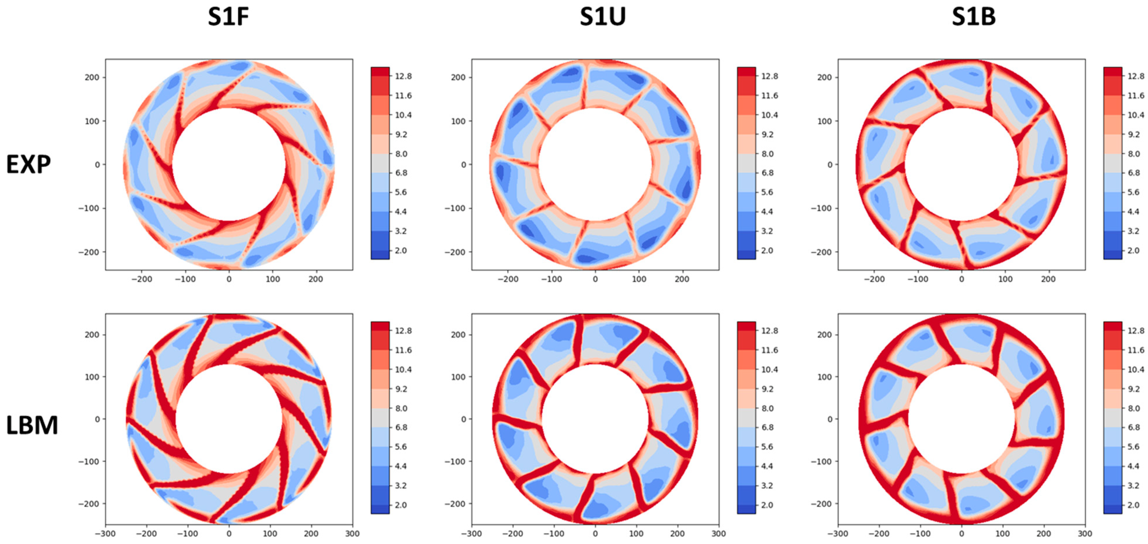
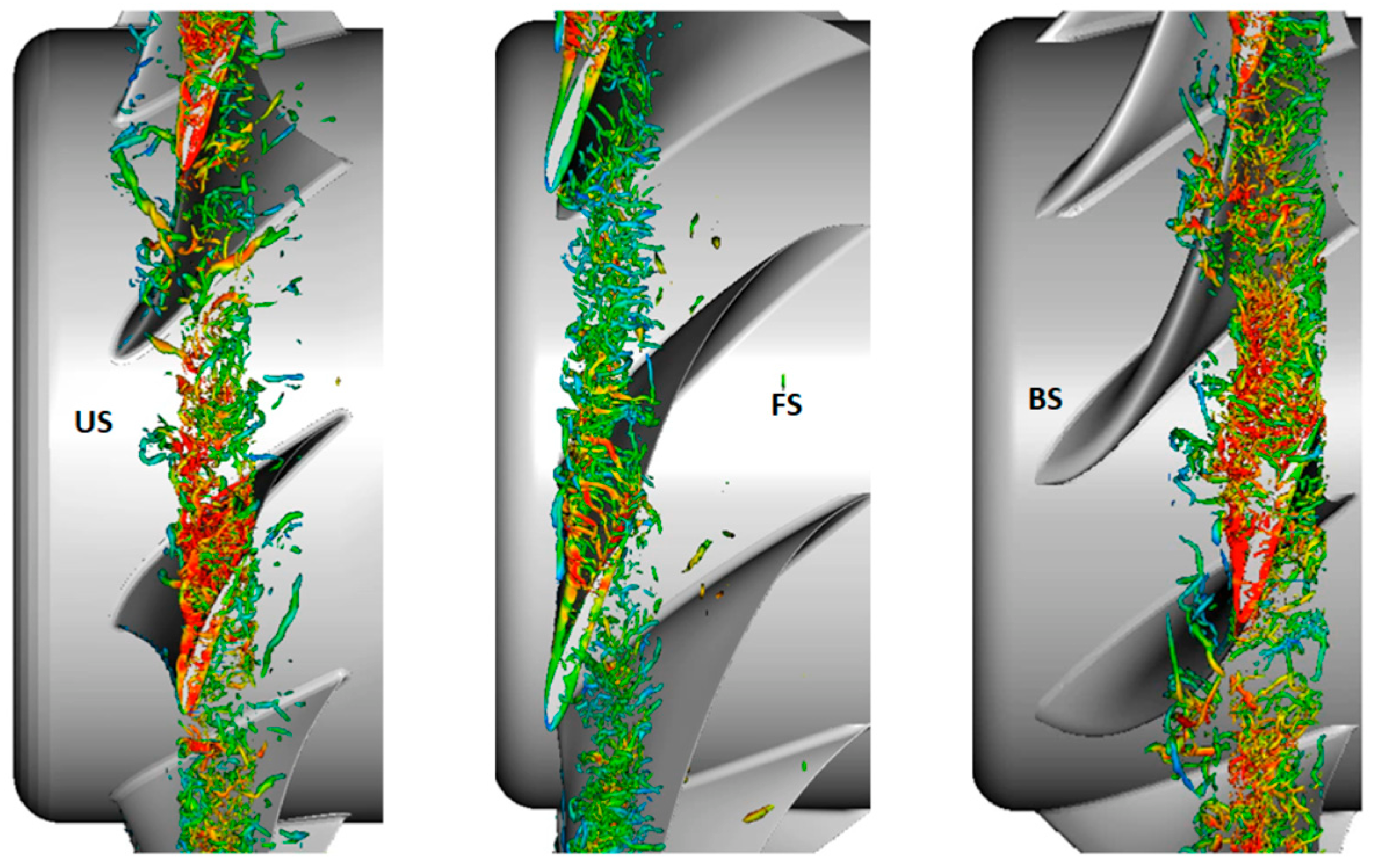
3.2.1. Aerodynamic Results

Good convergence of the overall pressure rise was achieved on the finer mesh (less than 10% difference). Consequently, most of the post-processing presented below is on the latter grid. Moreover, all comparisons are then made at the nominal flow coefficient of ϕ = 0.252, as this is the default operating point of the fans where their performance match by design.
The overall mean flow topology for the unswept fan case in the whole anechoic wind tunnel is presented in Figure 4. Similar flow features are obtained for the other two fans, as only the near-fields are modified by the blade design. The deflector in the inlet duct and the honeycomb grid to stop the jet in the plenum are necessary to insure a quasi-uniform flow at the duct inlet. The torque-meter and the frame holding the whole system are also seen to be far enough downstream not to create any significant flow blockage and induced potential interaction.
To get quantitative near-field aerodynamic validation, the LBM results can be compared to the LDA measurements upstream and downstream of the fan [8]. In Figure 5, the distributions of mean axial velocity in a plane perpendicular to the axis of rotation about 10 mm downstream of the fan trailing edge are shown for all three cases. Figure 6 displays the corresponding mean tangential velocity in the same plane. A good overall agreement is achieved between the experimental and numerical data. Only the blade wakes in the LBM simulations are thicker with slightly deeper velocity deficits and a larger tangential component below 75% of span. This is most likely due to the lower mesh refinement in the bottom part of the blade. Yet, at the tip, both the levels and patterns are closely matching thanks to the finest VR. Similar results are obtained for the radial component and in the upstream plane.
Good overall agreement is also achieved on the root-mean-squared velocity components downstream of the fan. Therefore, the mean flow field predicted by LBM matches the experimental one very well. Yet, as shown by the Ffowcs Williams and Hawkings’ acoustic analogy [18], noise sources in low speed fans come from the flow unsteadiness and particularly the wall-pressure fluctuations.
To assess the quality of the numerical predictions in the tip region where the effect of the blade sweep is felt the most, comparisons with the wall-pressure measurements of the probes placed on the stationary shroud in the tip region are achieved. The latter are shown with respect to the blade position in Figure 7. As the blade skew modifies the relative position of the probes with respect to the tip region, this is specified in each comparison with a given fan. Figure 8 shows the power spectral density (PSD) of the wall-pressure on probes 4 (left), 7 (middle) and 10 (right) for the S1F (top), S1U (middle) and S1B (bottom) fans, respectively. Note that these PSD have all been obtained with the Pwelch function implemented in Matlab with a 6 Hz bandwidth and a Hanning windows with 10% overlap for both numerical and experimental data to make a fair comparison. Excellent comparison between experiment and LBM results is achieved on all probes and for all fans (at least up to 1.5 kHz), which suggests that the vortex dynamics in the tip gap is well captured for the relevant largest structures (the wall-pressure fluctuations being the trace on the wall of all turbulent eddies developing above it). Moreover, the BPF and many of its harmonics are seen on all probes inside the tip gap for all fans. The BPF and some harmonics are also seen before and after the tip gap in the US and BS configurations. Only the FS case does not show any tones outside the tip gap, with the lowest broadband levels, suggesting the weakest flow recirculation in the tip gap.
To confirm the above observations on wall-pressure fluctuations, iso-contours of instantaneous Λ2 criterion (second invariant of the velocity tensor) that identify eddies in a turbulent flow, colored by the velocity magnitude, are shown in Figure 9 in the tip region. The view from the top of the fan is selected to highlight the interaction of the tip vortices with the blade. Clearly, the tip vortices with a Tip Leakage Vortex (TLV) leaving at the blade leading edge, interact more strongly with the blade in the US and BS configurations. They also have a higher velocity, which reinforces the impact. In the unswept case (US), the tip vortices interact with the whole blade chord, and in the backward swept case (BS), the tip vortices move even more upstream and strongly interact with the blade leading edge and TLV. Only in the forward swept case (FS), the tip vortices graze along the next blade, and potentially interact with the blade trailing edge only. This consequently explains the lowest wall-pressure fluctuations observed in this configuration in Figure 8.

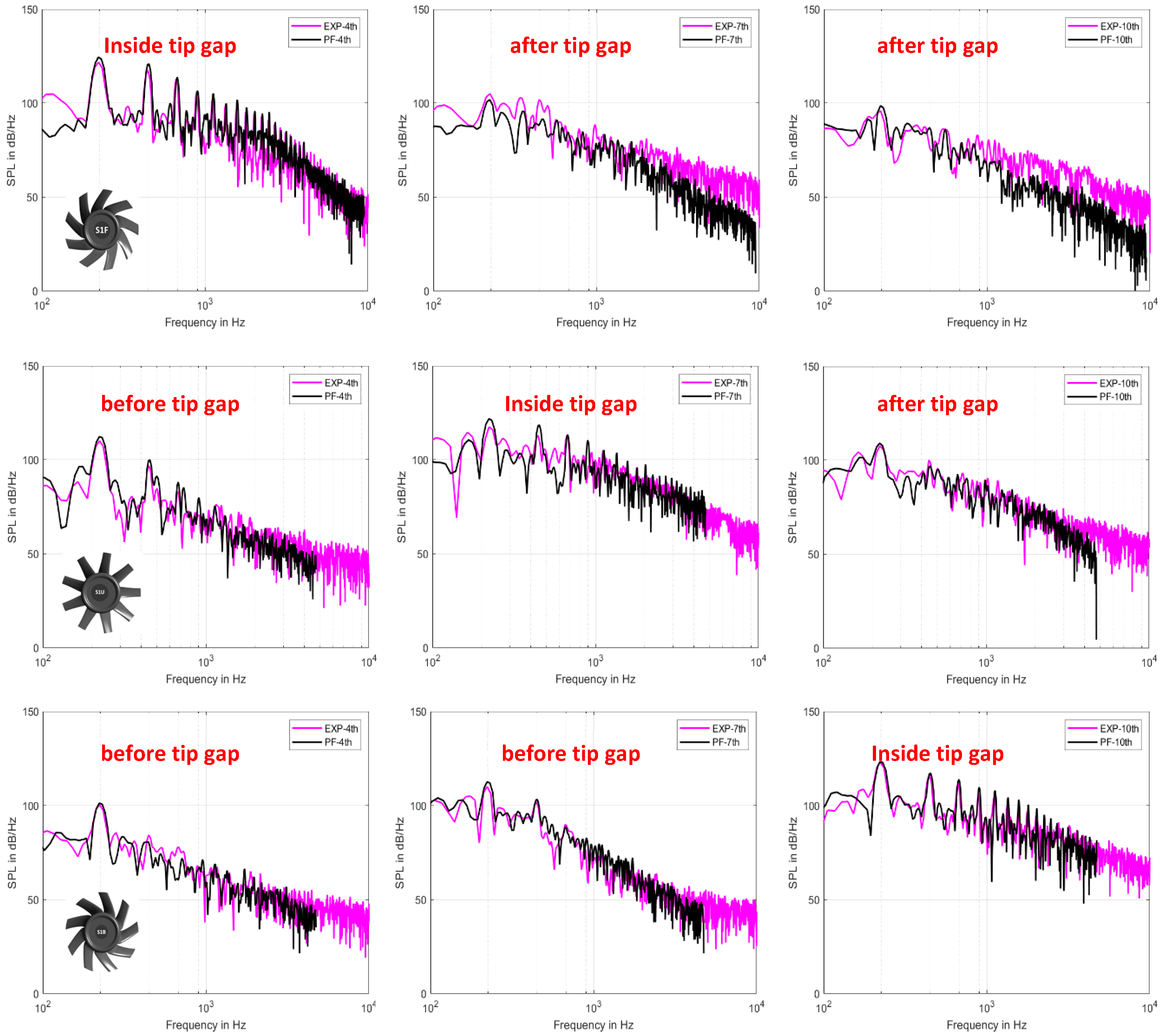
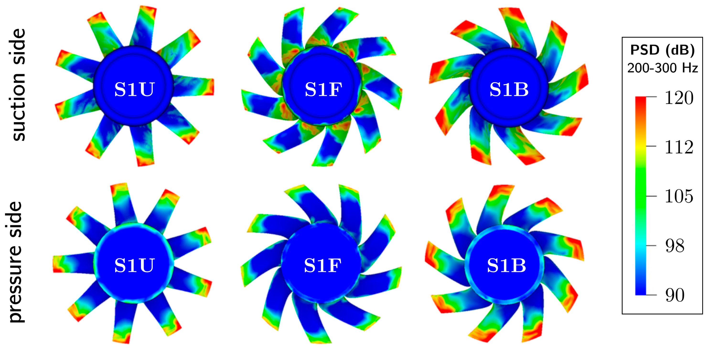
3.2.2. Acoustical Results

The far-field acoustic pressure is directly recorded at each location shown in Figure 2 (right), for 17 revolutions for each fan simulation with a sampling frequency of 47.3 kHz. Note that The PSD of the far-field acoustic pressure obtained numerically for the three fans are plotted in Figure 10 for microphone 4 placed in front of the duct on the fan rotational axis. In the latter plot, the vertical dashed lines correspond to the first two BPF. Note again that these PSD all have a 6 Hz bandwidth for both numerical and experimental data to make a fair comparison, and have been obtained with the Pwelch function implemented in Matlab and a Hanning windowing with 10% overlap. The first three plots compare the LBM results on the finest mesh with the measured spectra. The broadband noise levels and spectral shapes are well reproduced (within a dB) over the whole frequency range for all three fans (Figure 10a–c) for the S1F, S1B and S1U fans, respectively). Similar good comparisons have also been obtained on the other microphones. Only the peaks seen at the BPF harmonics in the experiment are not captured. As was shown previously by Sturm et al. in the anechoic wind tunnel at Siegen Universität [19], these tones are caused by the slight asymmetry of the installation of the fan system in the test rig as seen in Figure 3 and Figure 4. The jet entering the chamber is not completely diffused by the honeycomb screen and its direction not perfectly aligned with the fan system axis, yielding a slight difference of flow recirculation at the top and bottom of the test rig as evidenced for instance by the velocity contours in Figure 4 for the unswept fan. This flow distortion ingested by the fan in turn induces the tonal noise contribution. This was actually verified on the coarse mesh for the unswept fan by running a much longer simulation over the whole filling time of the test facility, as was done previously by Sturm et al. [19].
In Figure 10d, the three predicted spectra are compared. Clearly, a very different behavior is seen below and beyond 2 kHz. At low frequencies (below 2 kHz), the forward swept fan has much lower levels than the other two, with two strong subharmonic humps appearing below the BPF and its first harmonic for the unswept and backward swept fans. Such humps have been previously associated with large vortical structures appearing in the tip gap by Magne et al. [20] and Moreau and Sanjosé [17], and shown by Zhu et al. [21] to be the same phenomenon as rotational instabilities previously evidenced by Kameier and Neise [22]. The frequency range also corresponds to dominant tip noise as found by Moreau and Sanjosé [17] and Sanjosé and Moreau [23]. At high frequencies (beyond 2 kHz), all spectra merge, which may correspond to the trailing-edge noise contribution expected to be similar as the fan have the same profiles operating at the same (or similar) flow condition as mentioned above.
To get further insight in the noise sources, iso-contours of wall-pressure fluctuations filtered around selected frequencies have been studied, as they correspond to the main noise sources on a fan at low Mach number. Figure 11 shows the PSD of such fluctuations around 350 Hz (the largest subharmonic hump below BPF2). High wall-pressure fluctuations are seen in the tip region for the US and BS fans on both suction and pressure sides, stressing the strong impact of tip vortices with the blades in these cases as already shown in Figure 9. Note that the BS case even show the highest levels with the largest spanwise trace on the blades: the vortices in Figure 9 are not only larger and more energetic, but they also plunge farther toward the hub. For the FS fan, the largest levels are actually at the hub, caused by the local secondary flow features (corner vortex). Similar results are found from 150 Hz up to 2 kHz stressing the importance of tip noise in this frequency range, as already aforementioned.

4. Conclusions

The effect of blade sweep on axial fan noise has been studied numerically with the Lattice-Boltzmann method. A family of free-vortex axial fans designed and tested at Friedrich-Alexander Universität have been simulated in their actual test configurations. Good overall performances have been predicted and the detailed velocity maps before and after the fan also compare well with the previous LDA measurements for all three fans with various sweep. Excellent agreement is finally achieved on all spectra of the wall-pressure fluctuations in the tip gap where most of this low-speed fan noise is expected. Some clear difference is noticed between the forward swept fan and the other two fans: the latter have higher wall-pressure levels and more tonal content over a wider region in the tip gap. These fluctuations are the traces of the tip vortices that are stronger and occupy a larger area in the unswept and backward swept cases. The analysis also shows that the tip vortices stay in the rotational plane for the unswept fan, that they move even forward in the backward swept case, whereas they are more convected downstream in the forward swept case with hardly any interaction with the next blade. Thus, fan sweep alters the aerodynamic flow field significantly. Moreover, as previously shown in ring fans, these strong interactions of the tip vortices with the fan blades are responsible for large subharmonic humps in the far-field acoustic spectra, and consequently contribute to the large increase of noise in the unswept and backward swept fans compared to the forward case. The simulated noise spectra compare very well with experiment both in terms of levels and shapes. These spectra and the corresponding wall-pressure maps on both suction and pressure sides of all fan blades confirm the dominant tip noise in such low-speed axial fans, particularly in the most annoying frequency range below 2 kHz.
The LBM simulations have brought new insight in the particular role of the leakage flow on the noise emission. The sweep angle is a fan parameter that might be used to limit the blade-vortex interaction and to improve future fan designs.

Author Contributions

Conceptualization, D.G. and S.M.; methodology, M.S., S.M. and M.H.; formal analysis and investigation, D.G. and S.M.; data curation, D.G. and M.S.; writing—original draft preparation, S.M.; writing—review and editing, S.M. and M.S.; visualization, D.G. and M.S.; supervision, S.M.; project administration, S.M. and M.H.; funding acquisition, S.M. All authors have read and agreed to the published version of the manuscript.

Funding

This research was funded by Valeo (France) through the Chaire Aéroacoustique de l’Université de Sherbrooke.

Institutional Review Board Statement

Not applicable.

Informed Consent Statement

Not applicable.

Data Availability Statement

Not applicable.

Conflicts of Interest

The authors declare no conflict of interest.

References

  1. Moreau, S. A Review of Turbomachinery Noise: From Analytical Models to High-Fidelity Simulations. In Fundamentals of High Lift for Future Civil Aircraft; Springer: Cham, Switzerland, 2021. [Google Scholar]
  2. Carolus, T.; Beiler, M. Skewed blades in low pressure fans—A survey of noise reduction mechanisms, AIAA 97-1591 paper. In Proceedings of the 3rd AIAA/CEAS Aeroacoustics Conference, Atlanta, GA, USA, 12–14 May 1997. [Google Scholar]
  3. Grasso, G.; Roger, M.; Moreau, S. Analytical model of the source and radiation of sound from the trailing edge of a swept airfoil. J. Sound Vib. 2021, 493, 115838. [Google Scholar] [CrossRef]
  4. Krömer, F.J.; Moreau, S.; Becker, S. Experimental investigation of the interplay between the sound field and the flow field in skewed low-pressure axial fans. J. Sound Vib. 2019, 442, 220–236. [Google Scholar] [CrossRef]
  5. Zarri, A.; Christophe, J.; Moreau, S.; Schram, C. Influence of Swept Blades on Low-Order Acoustic Prediction for Axial Fans. Acoustics 2021, 2, 812–832. [Google Scholar] [CrossRef]
  6. Pérot, F.; Kim, M.S.; Moreau, S.; Henner, M.; Neal, D. Direct Aeroacoustics Prediction of a Low Speed Axial Fan, AIAA 2010- paper. In Proceedings of the 16th AIAA/CEAS Aeroacoustics Conference, Stockholm, Sweden, 7–9 June 2010. [Google Scholar]
  7. Moreau, S. Direct Noise Computation of Low-speed Ring Fans. Acta Acust. United Acust. 2019, 105, 30–42. [Google Scholar] [CrossRef]
  8. Zenger, F. Sound Emission of Low-Pressure Axial Fans under Distorted Inflow Conditions. Ph.D. Thesis, Friedrich-Alexander-Universität, Erlangen, Germany, 2017. [Google Scholar]
  9. Herold, G.; Zenger, F.; Sarradj, E. Influence of blade skew on axial fan component noise. Int. J. Aeroacoustics 2017, 16, 418–430. [Google Scholar] [CrossRef]
  10. Schoder, S.; Junger, C.; Kaltenbacher, M. Computational aeroacoustics of the EAA benchmark case of an axial fan. Acta Acust. 2020, 4, 22. [Google Scholar] [CrossRef]
  11. Chen, S.; Doolen, G.D. Lattice Boltzmann Method for Fluid Flows. Annu. Rev. Fluid Mech. 1998, 30, 329–364. [Google Scholar] [CrossRef] [Green Version]
  12. Chen, H.; Teixeira, C.; Molvig, K. Realization of Fluid Boundary Conditions via Discrete Boltzmann Dynamics. Int. J. Mod. Phys. C 1998, 9, 1281–1292. [Google Scholar] [CrossRef]
  13. Chen, H.; Orszag, S.A.; Staroselsky, I.; Succi, S. Expanded analogy between Boltzmann kinetic theory of fluids and turbulence. J. Fluid Mech. 2004, 519, 301–314. [Google Scholar] [CrossRef]
  14. Fares, E. Unsteady flow simulation of the Ahmed reference body using a lattice Boltzmann approach. Comput. Fluids 2006, 35, 940–950. [Google Scholar] [CrossRef]
  15. Avallone, F.; van der Velden, W.C.P.; Ragni, D.; Casalino, D. Noise reduction mechanisms of sawtooth and combed-sawtooth trailing-edge serrations. J. Fluid Mech. 2018, 848, 560–591. [Google Scholar] [CrossRef] [Green Version]
  16. Marié, S. Etude de la Méthode Boltzmann sur Réseau pour les Simulations en Aéroacoustique. Ph.D. Thesis, Université Pierre et Marie Curie, Paris, France, 2008. [Google Scholar]
  17. Moreau, S.; Sanjose, M. Sub-harmonic broadband humps and tip noise in low-speed ring fans. J. Acoust. Soc. Am. 2016, 139, 118–127. [Google Scholar] [CrossRef] [PubMed]
  18. Williams, J.E.F.; Hawkings, D.L. Sound Generation by Turbulence and Surfaces in Arbitrary Motion. Phil. Trans. R. Soc. Lond. 1969, 264, 321–342. [Google Scholar]
  19. Sturm, M.; Sanjosé, M.; Moreau, S.; Carolus, T. Aeroacoustic Simulation of an Axial Fan including the Full Test Rig by using the Lattice Boltzmann Method. In Proceedings of the Fan 2015 Conference, Lyon, France, 15–17 April 2015. [Google Scholar]
  20. Magne, S.; Moreau, S.; Berry, A. Subharmonic tonal noise from backflow vortices radiated by low-speed ring rotor in uniform inlet flow. J. Acous. Soc. Am. 2015, 137, 198–225. [Google Scholar] [CrossRef] [PubMed]
  21. Zhu, T.; Lallier-Daniels, D.; Sanjosé, M.; Moreau, S.; Carolus, T. Rotating coherent flow structures as a source for narrowband tip clearance noise from axial fans. J. Sound Vib. 2018, 417, 198–225. [Google Scholar] [CrossRef]
  22. Kameier, F.; Neise, W. Experimental Study of Tip Clearance Losses and Noise in Axial Turbomachines and Their Reduction. J. Turbomach. 1997, 119, 460–471. [Google Scholar] [CrossRef]
  23. Sanjose, M.; Moreau, S. RANS based analytical modeling of broadband noise for a low-speed fan. J. Acous. Soc. Am. 2018, 143, 198–225. [Google Scholar] [CrossRef] [PubMed]
Figure 1. Investigated fans; left: unswept (US); center: forward swept (FS); right: backward swept (BS). Note the rotational direction is clockwise.
Ijtpp 07 00034 g001
Figure 3. Computational domain and refinement volume definitions of the anechoic test facility at Friedrich-Alexander Universität with a zoom on the ducted fan section. Red square: rotating domain.
Ijtpp 07 00034 g003
Figure 4. Mean results for the unswept fan case: (a) static pressure; (b) velocity magnitude.
Ijtpp 07 00034 g004
Figure 5. Mean axial velocity at the trailing edge: comparison of experiment (top) and LBM results (bottom) for S1F (left), S1U (middle), and S1B (right) fans. Fan dimensions in mm and velocity in m/s.
Ijtpp 07 00034 g005
Figure 6. Mean tangential velocity at the trailing edge: comparison of experiment (top) and LBM results (bottom) for S1F (left), S1U (middle), and S1B (right) fans. Fan dimensions in mm and velocity in m/s.
Ijtpp 07 00034 g006
Figure 7. Sketch of the probes located in the casing to record unsteady wall pressure.
Ijtpp 07 00034 g007
Figure 8. PSD of wall pressure at probes 4 (left), 7 (middle) and 10 (right) for S1F (top), S1U (middle) and S1B (bottom) fans; the relative position of the probes w.r.t the tip gap is shown at the top of each plot.
Ijtpp 07 00034 g008
Figure 9. Iso-contours of instantaneous Λ2 colored by velocity magnitude for S1U (left), S1F (middle) and S1B (right) fans.
Ijtpp 07 00034 g009
Figure 10. PSD of far-field acoustic pressure for: S1F (a), S1B (b), S1U (c) and all (d) fans at microphone 4 shown in Figure 2. The vertical dashed lines identify the BPF.
Ijtpp 07 00034 g010
Figure 11. PSD of wall-pressure filtered around 350 Hz for S1U (left), S1F (middle) and S1B (right) fans. Suction (top) and pressure (bottom) sides of the fan blades.
Ijtpp 07 00034 g011
Publisher’s Note: MDPI stays neutral with regard to jurisdictional claims in published maps and institutional affiliations.

