1. Introduction
Boundary-layer flow separation is a generic problem in turbomachinery. Flow separation can be described as the ejection of fluid from the boundary layer toward the flow away from the wall [
1]. A back-flow zone in the flow is associated with this fluid ejection. The origin of the flow separation can be divided into two families, a strong adverse pressure gradient or an important curvature of the wall geometry.
The effects of flow separation are generally undesirable and can be detrimental in turbomachinery. From an energetic point of view, the flow separation induces supplementary losses. The energy used in flow separation is not available for the work exchange. The blades of the rotor can suffer from flow separation: the flow does not follow the aerodynamic airfoil; therefore, the work exchange between the rotor and the fluid is less performant. On some occasions, the separation can rotate with a rotation speed different from the rotor speed around the circumference of the compressor. This rotating stall induces periodic fluctuations and is a classical precursor to the compressor surge [
2]. This phenomenon also affects centrifugal pumps. For diffusers, flow separation can induce blockage zones that decrease the pressure recuperation. For example, flow separation in hydraulics bulb turbines is suspected to induce an important and sudden drop-off of the efficiency curves with operating fluctuations near the best efficient point [
3]. In other cases, the flow separation is not periodic in the diffuser and induces a non-periodic flow, as observed in a hydraulic turbine by [
4] and in a centrifugal compressor by [
5]. Another effect of separation is to increase the width of the blade wakes, which, in multistage configurations, can induce complex rotor–stator interactions all along the machine [
6]. Finally, flow separation might also generate undesirable low-frequency noise. This is the case in wind turbines operating at high loading conditions [
7].
In turbomachinery, the two main objectives are often to increase the performance and the operability of the machine, which are both limited by flow separation. In such configurations, the flow exhibits complex patterns as it is generally three-dimensional, confined, highly unsteady and might be highly turbulent. A frequent misleading practice to analyze a three-dimensional separation in engineering applications is to track back-flow velocity vectors in the 3D field to look for the flow separation. This method is doomed to fail in several situations, notably because a velocity vector in the 3D field can be in back flow without any flow ejection from the boundary layer. Indeed, the swirling flow within a conical duct induces a re-circulation zone without boundary-layer flow separation [
8]. Secondly, a fluid ejection from the wall can occur even if there is no back flow. In addition, the flow direction can be hard to define in complex geometry cases. Another, or complementary, misleading practice is to track points on the surface where skin friction is null. In three-dimensional cases, flow ejection from the boundary layer can happen all along the separation line where the skin friction is not necessarily null. Pragmatically, a local indicator of the separation occurrence at a flow-specific location does not exist. Hence, the analysis can not only be focused on each point individually but has to be performed with regard to the neighborhood and has to take into account the connection to the wall. Without any preliminary survey, to lead such an analysis in the 3D field directly is a nearly impossible task to fill. In external aerodynamics, a study of friction-line patterns on wall surfaces is commonly run first [
9]. Such an analysis requires an accurate determination of the critical points distribution, which is overseen by a topological rule-based approach. To respect the topology rule ensures to develop a scenario that fits physical principles. All in all, the skin-friction-lines analysis helps to pinpoint the origin of the flow separation at the wall to then ease the global 3D field examination. This technique is used in turbomachinery as well (for example, [
3,
4,
10]), but according to the authors’ knowledge, its adaptation for internal flow has not been clearly exposed yet. However, it is not straightforward. In comparison with the classical methodology on a flat plane, the following particularities of the turbomachinery context must be treated carefully:
The surfaces considered are more complex (characterized by the surface genus) than a simple flat plane.
Only a part of the system is represented, so the skin friction lines can be generated (source) and destroyed (sink) out of the analysis domain. Nevertheless, the skin friction source-and-sink representation is mandatory and has to be fictitiously re-located into the computational domain (see
Section 3.2).
For the real-world surfaces here studied, critical points can indeed be representative of a boundary flow separation but also indicative of a flow bypassing. Hence, they are no use for the analysis to be performed.
The partial representation of a component is mainly motivated by minimizing the CPU time. For instance, the periodicity assumption is commonly used to that end in turbomachinery. However, its use can be conflicting with the topological rule-based approach.
According to the needs previously exposed, to develop guidelines to better understand flow separations in turbomachinery appears to be necessary. A topology rule-based methodology is here proposed that ensures to find an admissible counting of critical points and that helps to distinguish the critical points that are connected to the flow separation zone in the turbomachinery context. This preliminary study aims at piloting the 3D analysis of the flow separation zone.
In the first part, the dedicated vocabulary and the concept of critical point analysis in general fluid mechanics are presented. The particularities of the analysis in turbomachinery are then discussed. The following part is organized in the recommended chronology to conduct the analysis: (1) determine the genus of the surface of interest, (2) determine the splitting critical points induced by the surface division, (3) determine the stagnation and exit nodes, (4) apply a periodicity and (5) check the topology rule. Finally, the last section illustrates the whole methodology with an application on the radial diffuser of an industrial radial compressor.
2. Theoretical Background
In this part, the authors try to clearly present the useful vocabulary and mathematical rules for an engineering approach.
To determine the correct topology rules to apply, the solid turbomachinery geometry (3D) needs to be simplified into a global one-piece surface (2D). In other words, only the “skin” of the solid is considered for studying topology. For instance, a solid ball (3D) is then turned into a sphere (2D). A one-piece surface is said to be connected. The complexity of a connected surface can be characterized by an integer called the genus, denoted as
g. The most general definition of the genus corresponds to the maximum number of cuttings along the surface without disconnecting it [
11]. As classical examples [
12,
13], a sphere has genus 0; a torus has genus 1; and a two-torus (two tori connected like an infinity symbol) has genus 2.
To avoid unnecessary alternative definitions, let us consider connected orientable closed surfaces. The definition of an orientable closed surface is given in
Appendix A. In practical cases, the classical real-world surfaces encounter these properties. For a surface as previously defined, the genus is related to the Euler characteristic
as follows:
By definition, two spaces are homeomorphic if a set of continuous stretching and bending that transforms one of the two surfaces into the other exists. For instance, a well-known surface homeomorphism links the coffee mug to the torus. These spaces are the same from a topological viewpoint. They have the same topological properties, notably the Euler characteristic. According to Equation (
1), two homeomorphic classical real-world surfaces also have the same genus. In this case, Equation (
1) is the easiest relation to determine the Euler characteristic.
These considerations on surfaces are useful for flow separation analysis because the Euler characteristic is linked to the number and the type of critical points. A critical point
is defined as a point on the wall where the skin friction
vanishes, i.e.,
This relation results from Poincaré’s research [
14] on differential equations and the application of this work to fluid mechanics by Legendre [
9] and Hunt [
15]. An analysis of the skin friction Jacobian matrix
(given in Equation (
2)) reveals that critical points can be related to only three types of skin friction patterns. They are then called the node, focus and saddle point. Node and focus can be either attracting if skin friction lines converge or repelling otherwise.
Figure 1 presents the corresponding skin friction patterns.
The link between the Euler characteristic and the critical points is expressed by the topology rule:
with
the number of nodes and foci, and
the number of saddle points.
A necessary condition for the three-dimensional separation occurrence is the convergence of the skin friction lines [
16]. Streamwise convergence of skin friction lines and near-wall streamlines induces a rapid lift of the near-wall streamlines away from the wall to conserve the mass flux through the stream tube [
17]. The convergence of friction lines is observed along one particular skin friction line, called the separation line, generally originating from a saddle point. The flow accumulated along the separation line is ejected from the wall to the flow field and is then accumulated along a three-dimensional surface called the manifold [
18].
As previously mentioned, real-world surfaces encountered are orientable closed surfaces. However, two common practices get out of the previous framework. The infinitely thin plane approximation of a real 3D geometry leads to either a non-orientable or a non-closed surface. The approximation of neglecting a small gap between two solid parts can alter the genus and then it yields to fallacious conclusions in the scope of a topological analysis.
In some exceptional cases, the skin friction pattern of a focus exhibits a closed path around a critical point. In this case, it is called a center or a limit cycle (skin friction lines form concentric circles around the critical point). Such cases have been determined by a theoretical approach by [
18]. On a limit cycle, the friction line can converge without a saddle point. This type of separation is called “open” flow separation, in opposition to “closed” flow separation that features a separation line bounded by two critical points.
3. Methodology
3.1. Surface Genus Determination
The first step is to determine the correct genus for the whole surface of interest, without any assumption of periodicity. The surfaces selected in this paper are particularly interesting for turbomachinery engineers. For these surfaces, the genus exists and is related to the Euler characteristic by Equation (
1) and allows to determine the topology rule Equation (
3). The topology rule ensures to respect a physical equilibrium between the different critical points types. They can have a genus of 0, 1 or related to the number of blades (
b).
Table 1 gives the genus for most common surfaces in turbomachinery. The last column of
Table 1 presents a simple example for each geometry as well as their genus determination. The maximum number of cutting planes before obtaining two parts for each surface family is illustrated with a plane distribution, in red. Of course, other cutting plane distributions can be found, but authors do not find any involving more cutting planes. In this article, only a blade without hole is presented. For example, turbine blades with external cooling holes are not included. A hole in a blade modifies the genus and requires a case-by-case study.
The “casing, pipe and vaneless diffuser” surface family corresponds to the numerous parts fully filled by the working fluid which conduct the flow without blades. Their genus is equal to 1 because all these surfaces are easy to obtain by continuous deformations of a torus. This one is independent of the longitudinal shape (diverging, converging, straight or not) and is also independent of the cross-section shape (circular, rectangular, etc). In the case of a part that is partially filled, e.g., a pipe that is not fully filled with water, the cross section of interest corresponds to the wetted cross section and is homeomorphic to a sphere (i.e., has genus 0). “Axial rotor” and “unshrouded centrifugal impeller” surfaces have genus 0. Any cutting plane divides the surface in two parts. These families include the large majority of rotating parts: fans, propellers, wind turbine rotors, jet engine compressors and turbines. The “shrouded centrifugal impeller” family is the only one known by the authors with a rotating part and a genus different from 0. This family corresponds to the case where the rotating part is composed of the blades, the hub and shroud. It includes some centrifugal compressors, centrifugal pumps and Francis turbines. For these shrouded rotors, the genus is equal to the number of blades. In this type of rotor, the number of splitter blades must be added if they are connected to both the hub and the shroud, and must not otherwise. The axial position of the leading edge or trailing edge has no effect on the genus. The “axial stator” and “radial vaned diffuser” are representative of classical stators of compressors. Their genus is also equal to the number of blades connected to the hub and the shroud. It is worth noticing that the assumption of neglecting a gap would wrongly transfer a geometry from one family to the other and yield an incorrect value of the genus. The last family of interest also presents a genus related to the number of blades. “Diffuser with parallel piers” category is representative of a hydraulic turbine draft tube with structural piers. The genus is here equal to the number of piers plus one.
3.2. Surface Partition and Splitting Critical Points (SCP)
Unlike turbomachinery cases, classical cases involve a surface that is completely immersed in the flow field. In turbomachinery, only the internal flow is considered and only a part of the system is analyzed. To be consistent with the topology rule, authors introduce imaginary critical points to take into account this partition of the domain (splitting critical points, SCP). This article is only focused on turbomachinery with confined flow. Hence, non-confined turbomachinery (wind turbine, propeller, for example) are disregarded. The friction field of interest is the one induced by the flow inside the turbomachinery; the outside flow is not considered. Next, as implicitly presented in the previous section, the zone of interest in turbomachinery is generally not the whole system from the fluid inlet to the fluid outlet but only a part of it. However, skin friction lines start and end at nodes (skin friction source and sink), which can be out of the zone of interest. From this observation, authors propose to introduce imaginary critical points that account for the development of the flow field upstream and downstream of the domain considered. They are referred to as splitting critical points (SCP). A preliminary caution to apply this methodology is to select a domain which includes the complete separation zone: the friction lines need to be relatively straight at the domain limits. Authors have found three types of SCP. The first one corresponds to a domain for which it was necessary to cut a shaft. In this case, an imaginary node needs to be added at the shaft center, as depicted in
Figure 2, to induce friction lines along its side. A practical application is the analysis of the second stage of an axial multistage compressor rotor. In reality, a node exists on the hub upstream of the first rotor, but this one is not present in the selected zone of interest and needs to be added as an imaginary node.
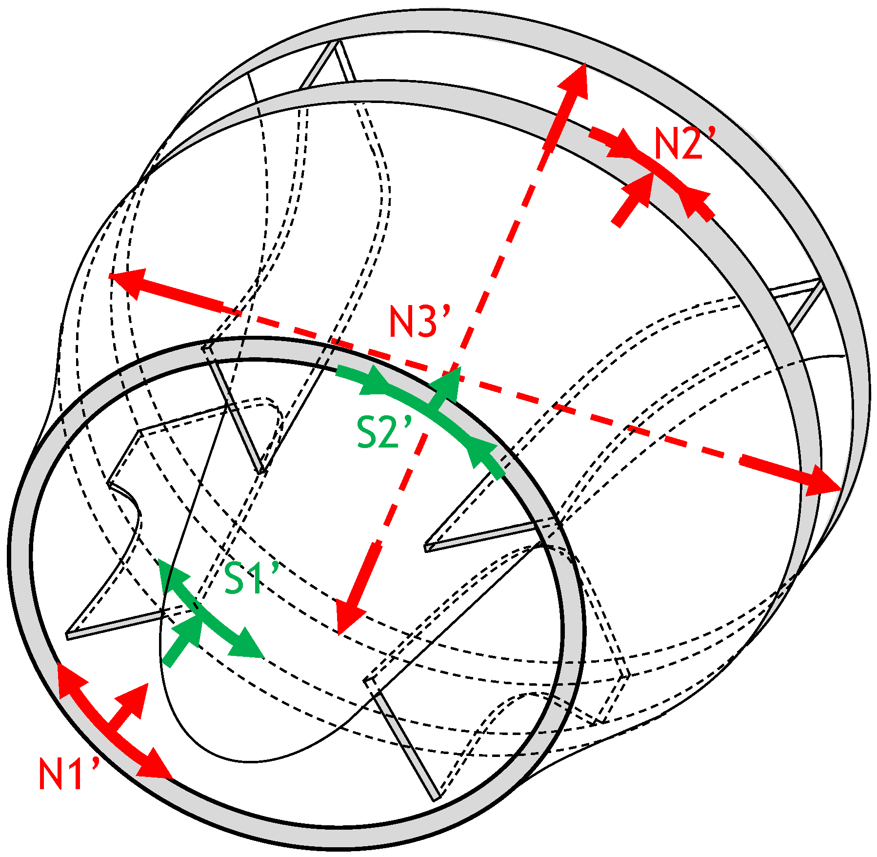
The next case is intrinsically linked to the confined-flow aspect. Let us consider a portion of a pipe extracted from a pipeline system, as illustrated in
Figure 3. The flow of interest is only the inner flow. An imaginary node (N1′,
Figure 3) is added to generate a friction line along the duct. The node also induces two friction lines which travel along the entrance periphery, one to the right and another on the left. Due to the closing, these two friction lines come together and induce a saddle point (S2′,
Figure 3) which induces a straight friction line along the cylinder. At the duct outlet, a saddle point (S1′,
Figure 3) collects the friction line originating from the entrance node and a node (N2′,
Figure 3) collects the friction line originating from the entrance saddle point. This pattern presented here with two pairs of saddle–node can be extended with an infinite even number of pairs. This mechanism is topologically neutral as it generates the same amount of saddle and node points.
The last type of SCP is useful to describe the outlet condition of radial turbomachines, such as an isolated unshrouded compressor impeller. The flow at the entrance is axial and radial at the exit. In this configuration, the friction lines tend to exit the machine radially, as illustrated in
Figure 4. In this case, the authors propose to place an imaginary node at the center of the exit circular section. This one corresponds to the imaginary intersection of friction lines at the exit of the impeller.
For a real surface, all these conditions can occur simultaneously.
Figure 5 presents the example of the SCP for a shrouded centrifugal pump impeller with a hub. In this case, the axial flow at the entrance reaches the hub and creates a node. This one is not represented in
Figure 5 as it is not an SCP. The hub surface induces a modification of the flow direction from the axial to the radial direction. To represent the radial friction lines on the hub surface at the impeller exit, an imaginary node is added (N3′). The flow on the shroud corresponds to the imaginary saddle–node combinations of an isolated portion of the casing (N1′, N2′, S1′ and S2′).
Furthermore, the recommended SCP for the topology analysis of each turbomachinery part presented is proposed in
Table 2.
3.3. Stagnation and Exit Nodes Inside the Domain
An interesting learning of the classical case of an object completely immersed in the flow is the stagnation node, where the upstream flow impacts the surface. This point is the source of the skin friction lines. These skin friction lines converge to an attracting node downstream where the flow exits the immersed object.
Let us consider the simple example of a sphere completely immersed in a uniform flow. A stagnation point appears on the side facing the flow, yielding a skin friction node from which friction lines diverge (stagnation node). In the same fashion, a skin friction node to which friction lines converge (exit node) appears on the opposite side. With the same idea, any overhang of the general shape inside the domain can feature a stagnation and/or an exit node. In the context of turbomachinery, a blade can be interpreted as such an overhang, with the stagnation point at the leading edge and the exit point at the trailing edge. Moreover, the nose of a hub exhibits a stagnation point at its tip. These nodes are physical and must be counted. Consequently, two nodes per blade should be counted, as well as one node per hub with a nose inside the considered domain.
3.4. Periodicity
The cost of a 360° numerical simulation is often prohibitive in turbomachinery. In most cases, a periodicity in the azimuthal direction naturally exists and can be used to obtain periodic solutions by replicating the flow field computed on a single channel. However, in the scope of the topological analysis, some caution is needed to properly restrain the surface of interest with this assumption and to adapt the topology rule. When periodicity is properly applied, conclusions on the whole system can be drawn from the study of a single periodic subdomain
For a genus-0 surface, with a periodicity assumption over a single or several channels, the observed subdomain should be considered as a genus-0 surface.
For connected orientable closed surfaces whose genus is strictly higher than zero, the issue of periodicity can be tackled by considering that the surface is homeomorphic to one or several tori. A genus-1 surface is homeomorphic to one torus and cannot be split. Here, this case corresponds only to the family “casing, pipe and vaneless diffuser”. This implies that if the goal of the simulation is to analyze flow separation on this type of surface, the simulation domain must include the whole surface.
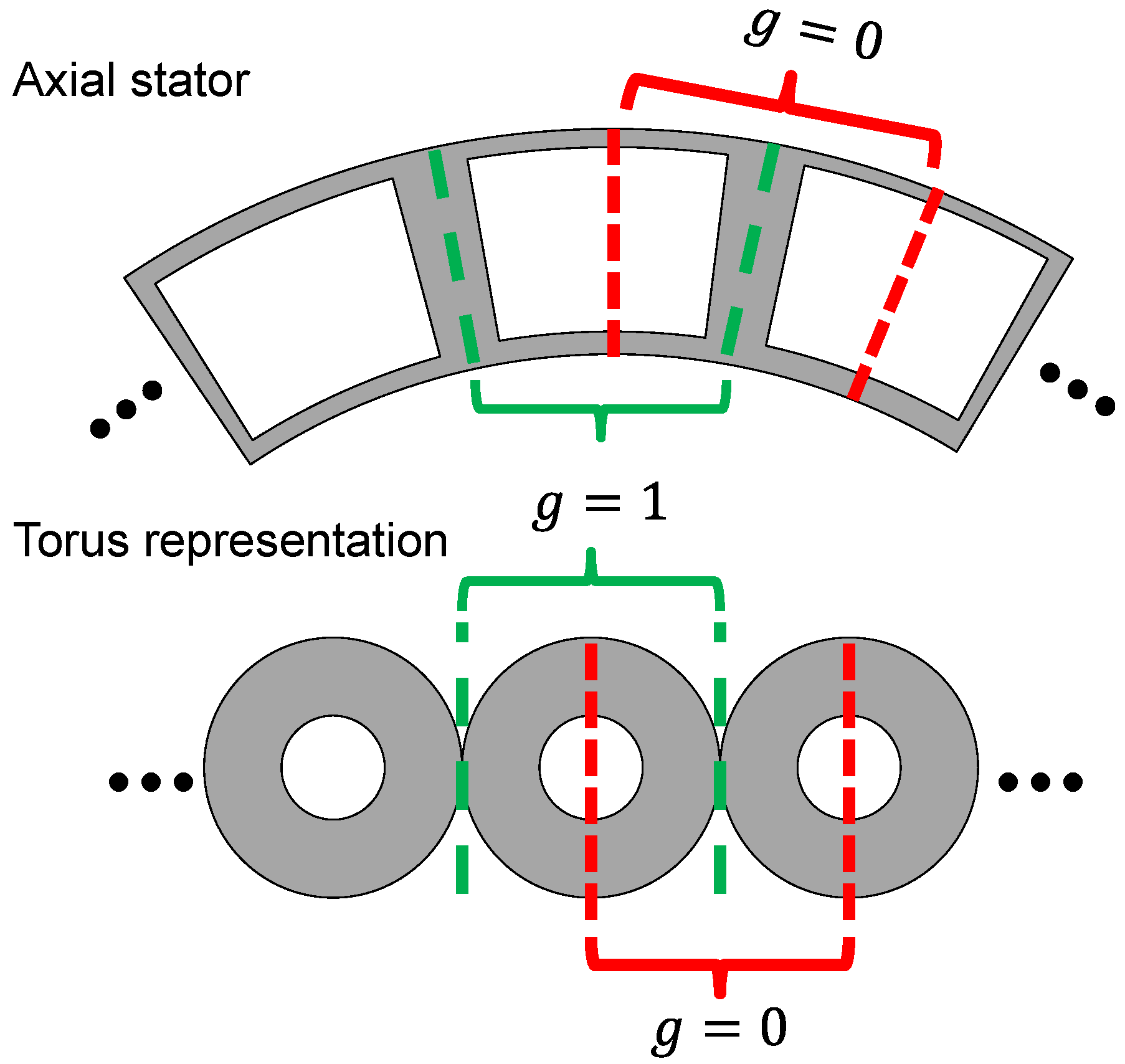
For genus-
b surfaces, the correct divisions only occur between two tori, illustrated in
Figure 6. The genus of the extracted surface corresponds to the number of tori kept. All genus-
b surfaces presented before are periodic in the azimuthal direction, and the number of tori corresponds to the number of interblade channels. Each torus is then formed by the junction of the blade pressure side surface, the two casing interblade surfaces and the blade suction side surface. Let us point out that, even though the flow physics is insensitive to the periodic pattern selected, this specific division is crucial in the context of a topological analysis. Indeed, an isolated blade bounded on both sides is a genus-0 surface, but an isolated interblade channel has a genus equal to one (see
Figure 6). Considering a subdomain centered on a blade can be tempting but leads to a false value of the genus.
In the case of the “diffuser with parallel piers” where genus is b + 1, the surface is not periodic. However, a symmetry plane between exit channels can exist. Each exit channel and the inlet channel can be represented by a torus. The exit tori then merge with the inlet torus. The symmetry plane must be placed at the junction between exit tori that respects the geometrical symmetry. To apply the symmetry assumption, the number of piers (b) must be odd, and the genus of the periodic subdomain is (b + 1)/2. Otherwise, the entire domain must be kept.
The next point of attention is the distribution of the critical points to check the topology rule. Three types of critical points must be distinguished: inside the periodic domain, from the subdomain splitting (SCP) and on the periodic boundary surface. The critical points which are located inside the periodic subdomain count completely. The number of these critical points in the complete surface is simply a periodic repetition of this pattern. The SCP are indivisible and count for the same quantity for a periodic subdomain and for the complete surface. A critical point on the periodic boundary surface counts as a half point in the periodic subdomain and one for the complete surface. For example, the stagnation node at the leading edge of a blade is counted as a half node if the point is on the periodic surface. If a critical point is on the two periodic surfaces, this point counts for one, in the periodic subdomain and in the complete surface. The classical example is the stagnation node at the hub which belongs to the two periodic surfaces.
3.5. Application of the Topology Rule
At this point of the analysis, the genus of the complete surface is known, the SCP are determined, the number of stagnation nodes are determined. The periodicity is applied on the analysis surface on the topological rule and on the critical point distribution. One should now check if the topology rule is correct.
If the topology rule is checked, the topological organization obtained corresponds to a situation without flow separation. From then, this organization can be compared to the actual skin friction field to look for supplementary critical points. If the skin friction field of interest exhibits more critical points than the one counted so far, the flow field features one or several separation zones, and the supplementary critical points are linked to these zones.
If the topology rule is not validated, the resulting topological organization is not physical. The topological organization, with or without flow separation, needs to check the topology rule. A first stage is to find a physical topological organization without flow separation. In turbomachinery, the problem often comes from the stagnation and exit nodes on a blade introduced in
Section 3.3. In this case, from authors’ experience, the topology rule is fulfilled by adding two saddle points representing the flow bypassing around the blade at the blade connection to the wall. One saddle point is placed upstream of the blade leading edge, the other downstream of the blade trailing edge. From then, this organization can be compared to the actual skin friction field to look for supplementary critical points.
The critical points symptomatic of a separation zone appear in saddle–node or saddle–focus pairs to respect the topology rule.
A tricky notion is that critical points from flow separation can interact with critical points from the geometry aspect. The knowledge of the topology without flow separation can help to distinguish critical points from different origins.
Let us underline that identifying critical points for a given skin friction field is not trivial. They can be detected manually by inspecting the low friction magnitude regions. If a large number of skin friction fields must be explored, automatic detection algorithms can be used [
19]. This is the case when characterizing the unsteadiness of a separation zone, for instance.
4. Application to an Industrial Radial Diffuser
In the framework of the Clean Sky 2 project FLORA, a Large-Eddy Simulation (LES) of an industrial centrifugal compressor was performed. The compressor has been designed and built by SAFRAN Helicopter Engines. This compressor is composed of inlet guide vanes, a backswept splittered unshrouded impeller, a splittered vaned radial diffuser and axial outlet guide vanes. Thanks to a natural periodicity in the azimuthal direction, the simulation domain is limited to 1/3 of the machine. A compressible LES has been performed using the code TurboAVBP developed at CERFACS [
20]. TurboAVBP is a single program–multiple data paradigm that encapsulates two instances of the unstructured massively parallel LES solver AVBP. Both rotor and stator domains are run simultaneously within the code and primitive variables are interpolated and exchanged using overset grids with the CWIPI library of Onera [
21]. The setup is similar to the one used in [
22] where the convective operator is discretized by the Lax–Wendroff scheme (2nd-order accurate) and an explicit time advancement [
23]. The Sigma [
24] Sub-Grid Scale model (SGS) is used and standard log-law is applied on all solid boundaries.
In this article, only the splittered vaned radial diffuser is considered. The flow field used is the average of unsteady solutions over approximately a 10-rotations period. To simplify the analysis, the LES solution is interpolated from an unstructured mesh with 114 million cells to a structured mesh with 6 million cells. Two-dimensional streamlines at the first cells are used as a proper approximation of the skin friction field. They are colored by the velocity magnitude.
The selected operating conditions are near the best efficiency and nominal speed. As presented in the following, the flow separation zones are small and have a restricted effect on performance. This case is easy to analyze and is selected for illustrating the presented methodology.
4.1. Surface Genus Determination
From
Table 1, the genus associated to a radial diffuser is equal to the number of main and splitter blades
b. The splitter blades count in the number of blades (these ones are connected to both the hub and the shroud). The surface remains continuous even if the surface is cut between each blade on the shroud surface. Any supplementary cut divides the surface into two parts. The exact number of blades cannot be provided due to the industrial property. The topology rule here is:
4.2. Surface Partition and Splitting Critical Point (SCP)
According to
Table 2, the extraction of the radial diffuser from the complete compressor induces four SCP: two radial nodes and two saddle–node combinations. The two radial nodes emit skin friction lines and are located at the hub and shroud surfaces on the compressor axis. The saddle–node combinations are located at the circular boundary on the hub and shroud surfaces. These saddle–node combinations produce an equal quantity of saddle and node points and are therefore topologically neutral.
4.3. Stagnation Node Inside the Domain
Two stagnation nodes are present on each blade. Thus, in the complete diffuser, there are 2b nodes.
4.4. Periodicity
Using homeomorphism, the radial diffuser is equivalent to
b-tori. Each torus is delimited by the blade suction side surface, the interblade shroud and hub surfaces and the blade pressure side surface. Let us recall that two different blade geometries exist, the main blade and the splitter blade. Consequently, to preserve the geometrical periodicity, the azimuthal periodicity is applied to 2-tori and the analysis domain is delimited by the suction side of one main blade and the pressure side of the next main blade. The analysis domain includes both sides of the splitter blade, as illustrated in
Figure 7. The shroud surface is set with low opacity to see the internal splitter blade. Consequently, the genus of this subdomain is
g = 2, and the topology rules yield:
4.5. Application of the Topology Rule
With previous considerations, the periodic subdomain contains six nodes (two half nodes at the main blade suction side, two half nodes at the main blade pressure side, two nodes from the splitter blades and two nodes from the SCP) and no saddle point (the SCP saddle–node combinations compensate themselves and are not counted here). As a result, Equation (
5) is not fulfilled.
The analysis of the skin friction field at the wall reveals a flow organization around each blade as depicted in
Figure 8. In the middle of the leading edge, the stagnation point (N1,
Figure 8) emits friction lines. They go along the sides of the blade, toward the blade tip and toward the blade root. The friction lines going toward the blade root induce a back-flow zone upstream of the leading edge of the hub surface. The friction lines on the hub surface coming from upstream are deviated around the back-flow zone and induce the saddle point (S1,
Figure 8). The friction lines emitted by S1 around the blade are collected by the saddle point at the trailing edge (S2,
Figure 8). The saddle point S2 emits friction lines that go downstream and along the trailing edge. A similar organization is found at the shroud surface (S3 and S4,
Figure 8). The exit node (N2,
Figure 8) collects the skin friction lines emerging from S2, S4 and N1.
From the authors experience, for a blade bounded by two surfaces, this topological organization is the simplest observed configuration and is symptomatic of a flow bypassing solid volumes.
As a summary, four saddle points and two nodes are attributed to the splitter blade. As the analysis domain is the interblade channel, two half main blades are considered and are attributed with eight half saddle points and four half nodes. With the two nodes from the SCP, the topology rule (
5) is now satisfied.
No flow separation zones have been introduced so far. This example was selected because the flow separation zones are expected to be small. It is therefore easier to divide the critical points into those related to the geometrical aspect and those occurring due to the flow separation. Indeed, this distinction is often challenging as all critical points can interact with one another. The skin-friction-lines analysis reveals five isolated zones of flow separation. In
Figure 9, the critical points at the hub surface are presented. The critical points related to geometrical aspects, indicated in green in
Figure 8, are indicated in green as well. The other critical points reveal three flow separation zones.
The first one, indicated in blue, is located at the junction between the main blade suction side and the hub, approximately at midchord. A zone with similar critical points distribution is observed on the shroud surface corner. The second one, indicated in yellow, is located downstream of the first one. In this case, such a zone is not observed at the shroud. Both separation zones are symptomatic of a corner separation. Indeed, in such a region, the adverse pressure gradient acts on the low-energy fluid from the corner boundary layer.
The last zone is indicated in grey and is located on the suction side of the splitter blade, close to the leading edge. The same topology is observed at the shroud surface. The friction lines on the suction side of the splitter are presented in
Figure 10. The enlargement presents the local critical points distribution on the hub surface with two saddle points and two foci. This separation zone is symptomatic of a local off-design flow incidence close to the hub and shroud. Such flow conditions can be explained by the passage flow occurring in the main channel, which drags the boundary-layer flow from the suction side of a main blade to the pressure side of the neighboring one. Moreover, the corner separation zones at the suction side (in blue and yellow,
Figure 9) can induce a blockage effect which contributes to the flow deviation.
The topological analysis as well as the analysis of the skin friction fields enable to characterize the visible critical points as a function of their origins. According to the methodology presented in this paper, this analysis can be extended from the periodic subdomain to the complete diffuser.
Table 3 summarizes the critical points count for both domains. Let us underline that Equations (
4) and (
5) are satisfied, respectively, for the periodic and the complete domain.
5. Conclusions
In this paper, a method is proposed to properly initiate the analysis of a three-dimensional flow separation using critical points. This method considers the specificities of the turbomachinery domain. The main steps of this analysis are:
Determination of the surface genus and the topology rule;
Determination of the splitting critical points (SCP) induced by the surface isolation from the total system;
Determination of the stagnation and exit nodes inside the domain, in particular, at the blade leading and trailing edge and at the nose hub;
A reduction in the analysis domain to a smaller subdomain, if a natural periodicity exists. The consequences on the topology rule and the critical points distribution are described;
A definition of topology with no flow separation that respects the topology rule. Flow regions that exhibit additional critical points are then highlighted, and their physical origins can be analyzed further.
The topology rule is a unique tool for finding all critical points and deducting flow separation mechanisms. However, it should be used with caution as a false topology rule can lead to misleading conclusions. This method helps to clarify the concept of genus, even for complex geometries and with domain restrictions, and consequently helps to properly apply the topology rule. Finally, as presented with the analysis of a radial diffuser, the evaluation of the topology without separation seems to be a good practice to group critical points from the geometrical aspect and from the flow separation zone.


