Article

HoberUI: An Exploration of Kinematic Structures as Interactive Input Devices

1
School of Computing and Communications, Lancaster University, Lancaster LA1 4WA, UK
2
School of Computer Science, University of Bristol, Bristol BS8 1UB, UK
*
Author to whom correspondence should be addressed.
Multimodal Technol. Interact. 2024, 8(2), 13; https://doi.org/10.3390/mti8020013
Submission received: 4 January 2024 / Revised: 30 January 2024 / Accepted: 6 February 2024 / Published: 13 February 2024

Abstract

:
Deployable kinematic structures can transform themselves from a small closed configuration to a large deployed one. These structures are widely used in many engineering fields including aerospace, architecture, robotics and to some extent within HCI. In this paper, we investigate the use of a symmetric spherical deployable structure and its application to interface control. We present HoberUI, a bimanual symmetric tangible interface with 7 degrees of freedom and explore its use for manipulating 3D environments. We base this on the toy version of the deployable structure called the Hoberman sphere, which consists of pantographic scissor mechanisms and is capable of homogeneous shrinkage and expansion. We first explore the space for designing and implementing interactions through such kinematic structures and apply this to 3D object manipulation. We then explore HoberUI’s usability through a user evaluation that shows the intuitiveness and potential of using instrumented kinematic structures as input devices for bespoke applications.

1. Introduction

Deployable structures are mechanical structures that have the capability to kinematically transform in a predictable manner and attain multiple predetermined configurations [1,2]. Use of these structures has attracted great interest in multiple fields of engineering due to their mechanical capability to deploy from a small undeployed configuration to an open, expanded one. A key advantage of these structures is that they can be described through a single kinematic degree of freedom (KDoF), i.e., the position of nodes or elements relative to the others [3,4]. Manipulation of a single node can be used to uniquely control and determine the geometry of the entire structure. Common examples include umbrellas, some origami shapes and scissor-like systems. These mechanisms have been extensively used in multiple applications including space deployment, reconfigurable architecture, foldable medical equipment and robotics [1].
Kinematic structures have also been explored in the context of Human–Computer Interaction (HCI). This has been particularly relevant to the goal of creating reconfigurable devices such as modular tangible user interfaces (TUIs) and shape-changing interfaces (SCIs). Notably, we have seen applications of kinematic structures within a pneumatic structure for creating modular furniture [5], self-expandable wearable fabrics [6,7] and for creating tabletop tangibles using linear scissor-based actuated mechanisms to increase their height on demand [8]. An entire class of systems have been developed based on explorations of kirigami [9,10,11,12] and metamaterials [13,14,15,16].
In this paper, we build on the related work of usage of kinetic structures within HCI by exploring a new form factor. We present HoberUI, a bimanual symmetric tangible interface with 7 degrees of freedom and explore its use for manipulating 3D environments as shown in Figure 1. HoberUI is based on a Hoberman sphere. A Hoberman sphere is a deployable structure consisting of pantographic scissor mechanisms and is capable of homogeneous shrinkage and expansion. We augmented the sphere with inertial and deformation sensing capabilities to sense users’ interactions. We demonstrate its usage as a 3D environment controller to interact with a solar system demonstrator application on a standalone display.
We conducted a qualitative user evaluation to investigate the use of HoberUI as a 3D controller and to gain a better understanding of the benefits of using deployable structures in the form of user experience. We found that there are many advantages to HoberUI, including its physical properties placing natural constraints on the interaction but also promoting bimanual usage and strong mapping with the 3D environment. Our study also identified a number of other application scenarios such as museum exhibits and the manipulation of biological materials and 3D objects. Our study also reveals that the mapping between physical input and virtual ones are not straightforward and that further investigation should be carried out to offer more intuitive and personalised interaction.
We draw on our qualitative results to highlight further considerations and research direction to push the field to use more kinematic mechanisms and highlight their potential as input devices for bespoke applications. In summary, our contributions are twofold. First, we contribute HoberUI, a new tangible interface to manipulate 3D environments. We then contribute an understanding of how such kinematic structures could be beneficial to user experience through a qualitative evaluation. The structure of the remaining paper follows the steps undertaken, as described above, to arrive at these contributions.

2. Related Work

The exploration of deployable kinematic structures as interactive input devices requires us to understand the prevalence of reconfigurable interfaces within HCI and the advantages of deployable kinematic structures and use these to motivate the design of a reconfigurable controller utilising a deployable structure based on scissor-like elements.

2.1. Reconfigurable Interfaces and Controllers

The motivation to create reconfigurable interfaces lies within the concept of shape-changing interfaces where an interactive artefact undergoes a change in shape and offers novel input modalities or affordances which emerge from active behaviour of the tangible [17,18]. HCI researchers have used different kinds of shape-changing structures towards creating reconfigurable UIs. This includes use of pneumatically actuated structures for modular furniture [5] and self-expandable wearable fabrics [6,7]. A more recent trend has been the focus on origami-based tessellations [19] and further inspired by kirigami. Kirigami-based designs derived from thin sheet actuators [9] and metamaterials [13] have been used to produce haptic swatches [10] actuator-designs [12] and demonstrate novel sensor designs [11]. Reconfigurable and metamaterials allow researchers to develop novel configurations as UI prototypes [14]. While kirigami has shown promising outcomes, there are other kinematic structures that are in use in engineering and architecture which could be adapted into reconfigurable UIs with engineered affordances and behaviours. Pairing these with metamaterials can be helpful [20,21], but the kinematic structures lend themselves to novel designs. For example, rolling-mechanism-based structures are used for a rollable display [22]. Other mechanisms include folding, which has also been applied to displays [19,23,24,25]. Other alternatives include modular folding, which has been explored to create reconfigurable objects made of tiny blocks [26,27,28]. The role of reconfigurable and tangible controllers is particularly useful for manipulating 3D environments. The reconfiguration can be minimal, e.g., Cubic mouse [29] and Button+ [30] or can result in an entirely different shape, e.g., KnobSlider [31]. Our motivation lies in the shape-change that can mirror the reconfiguration behaviour of real-world objects like a tube [32] or a Rubik’s cube [33]. Shape-changing input controllers are well-suited for virtual reality applications, especially ones using head-mounted displays, due to their ability to augment the experience with haptic and tangible feedback [34,35].

2.2. Deployable Kinematic Structures

In this paper, we step away from the inspirations emerging from kirigami and look at deployable kinematic structures defined in engineering and related fields, as structures designed to operate at supra-human scales with computable rigidity and stability, based on simple elements and materials that can withstand repeated actuation and operator mishandling. These deployable kinematic structures are designed to operate autonomously while avoiding unstable modes (or singularities in their control function). Such shape-changing structures are a well-studied concept in fields like engineering, architecture, construction and space technology. Within these fields, deployable structures are studied as special types of transformable structures, described by Pellegrino [36] as “Capable of executing large configuration changes in an autonomous way”. Hanaor and Levy [37] classify deployable structures based on their structural-morphological properties into kinematic rigid-link structures and deformable structures. Kent [3] defines a kinematic structure as one having a single KDoF, namely, the positioning of one node in the structure relative to the others, which uniquely determines the geometry of the entire structure. Looking at this definition inversely, a kinematic structure can respond to input to any one of its nodes and achieve the target geometry corresponding to the input. This provides HCI researchers with a highly flexible object with a parameterisable geometric shape (i.e., shape state), with multiple ways to control or manipulate the object into a desired shape. An additional advantage is that the object also requires minimal instrumentation to detect its shape state.

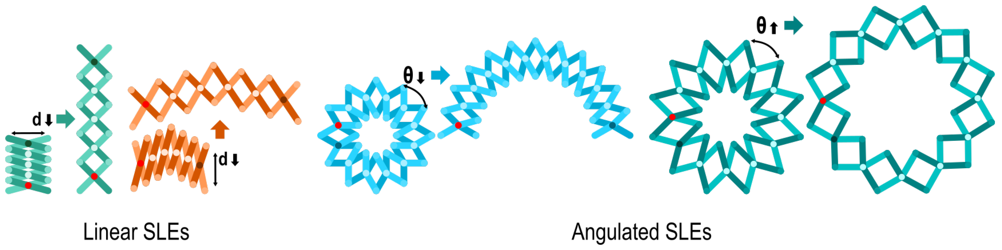
2.3. Scissor-like Elements (SLEs)

A rigid-link kinematic structure can alter its shape state through the connectors between the rigid links that form the structure. These connectors describe the available DoF, viz., a rotational DoF resulting from hinges and a translational DoF resulting from slides between the rigid links [37]. These individual connections contribute to the KDoF of the overall structure. The simplest example of a kinematic structure using rotational DoFs is a 4-bar pantograph using linear SLEs. Pantographic grids can be designed to produce a pre-determined and parameterised shape state (see Figure 2). The arrangement of the hinge points and relative bar size pre-determines the achievable shape states. This arrangement also determines the exact shape state for a given value of input, i.e., actuated rotation of any hinge, within a range of allowable inputs, produces a shape state as a function of the input. Another class of kinematic structures relies on the same DoFs as the linear bar pantographs but replaces the linear bar elements with angulated bar SLEs [38,39]. The angulated bar SLEs are commonly seen in 3D kinematic structures in architecture [1]. In architecture and engineering, the research focuses on the challenges of deploying and maintaining a kinematic structure at building-size scales. Within HCI, linear pantographic SLEs have been used as supporting sub-structures, examples of which include Xpaaand [22] and Changibles [8]. We explore the use of kinematic structures as shape-changing input controllers with the intention of understanding the challenges and opportunities available to exploit for the entire class of kinematic rigid-link structures.

3. HoberUI Implementation

The implementation of a tangible input device based on a kinematic structure can be carried out in three steps: (a) defining the characteristic shape state of the kinematic structure, (b) designing the input modalities based on the affordances of the kinematic structure and (c) instrumenting the kinematic structure to translate user action on the kinematic structure into interactive input. The design space of feasible kinematic structures relying on linear or angulated SLEs is vast [1], and its exploration is beyond the scope of this research. Existing research [37,38] provides a designer with the fundamental understanding required to design a kinematic structure with a specific shape state. For our exploration, we rely on an existing and well-known kinematic structure, the Hoberman sphere. Our choice of this structure as the basis of our exploration is opportunistic based on the wide availability of the kinematic structure as a toy. Our implementation, the HoberUI device, shares this similarity to previous research that relies on the Rubik’s cube [33] and Rubik’s Magic Puzzle [24].

3.1. Hardware Implementation

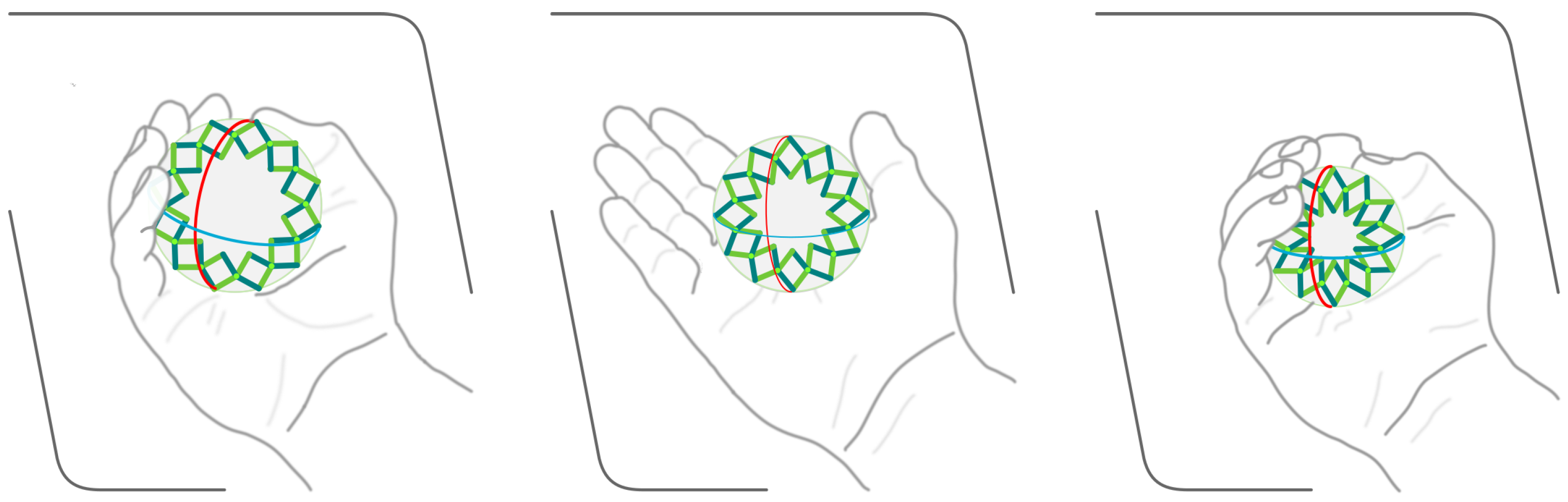
3.1.1. Hoberman Sphere

The Hoberman sphere consists of angulated SLEs linked in a 3D arrangement. The original design uses linkages arranged along the six greater circles of the enclosing sphere such that they align with the vertices of an icosadodecahedron. A multi-way hinge joint is used at the intersections of the greater circles, which can be three-way or five-way depending on the intersection. The links entering the hinge joint maintain their rotational DoFs perpendicular to the plane of the great circle to which they belong. Other configurations are also possible, and the commercially available version used in HoberUI consists of three greater circles arranged perpendicular to each other connected with four-way link joints. There are eight additional three-way link joints at the centre of each of the octants generated by the intersection of the three greater circles. The shape state of the Hoberman sphere is spherical, and the controllable parameter is the diameter. The Hoberman sphere is isokinematic, and thus the diameter of the Hoberman sphere can be described as a function of the angle between any of its linkages. Viewed as a kinematic shape, the Hoberman sphere is a variable size sphere and the size of the sphere can be changed by manipulating any of the diametrically opposite link joints which results in a change in the diameter of the sphere. From an affordance perspective, the Hoberman sphere can be held at any of its link joints and manipulated by applying force on the diametrically opposite link joint.

3.1.2. Input Sensing

Our sensing scheme relies on readily available components and is not prescriptive. The aim is to only demonstrate the feasibility of the prototype system. As a result, our implementation uses a BBC micro:bit [40] which has an onboard LSM303AGR tri-axis accelerometer and magnetometer. While the visual tracking approach using infrared sensors or depth cameras is well-documented and reliable, it adds to the overall form factor of the system and would reduce the capability of HoberUI as a plug-and-play device. This is further enforced by previous research also using on-board sensors instead of external hardware [29,41].
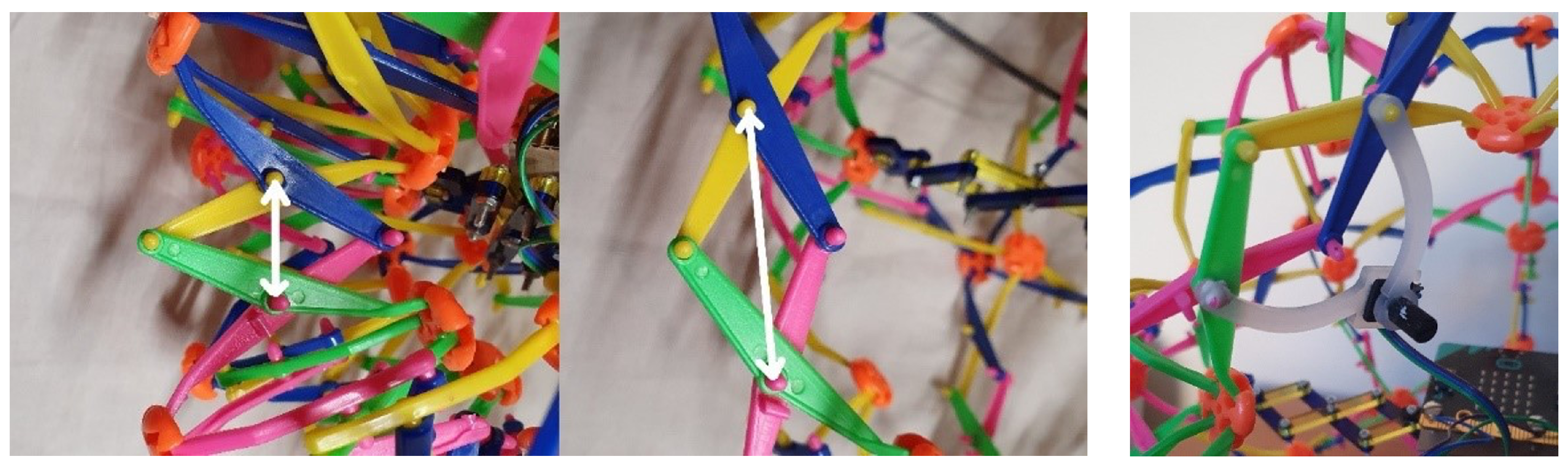
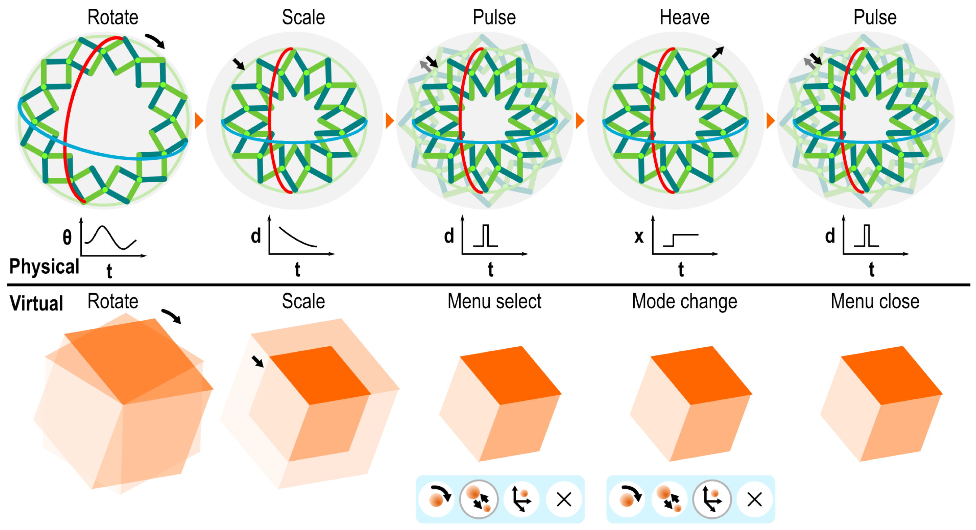
  • Shape state: The shape state of the Hoberman sphere is described by its diameter. This can be described by measuring the angle between the rigid links that constitute any of the SLEs of the Hoberman sphere. We used a single-turn potentiometer to measure this angle. The mechanical assembly (see Figure 3) consists of two rigid elements attached to adjacent hinge-points and forming a SLE linked together by the potentiometer as the hinge axis.
    As an isokinetic structure, the change in shape state of HoberUI always produces an exact parametric change in the potentiometer resistance. The micro:bit senses the change in resistance via one of its onboard analogue input pins. We also considered alternatives like a Force Sensitive Resistor (FSR), bend sensors and rotary encoders. However, we chose the SLE-mounted potentiometer as it presented as a more elegant solution.
  • Orientation: Orientation is sensed using a sensor-fusion approach inspired by Birdy [42] and PALLA [43]. The micro:bit provides tri-axis accelerometer and magnetometer readings based on the relative orientation of the micro:bit. We compute the orientation using the assumption that in the steady state, the only force acting on the accelerometer is gravity. In the default “upright” state, the gravity vector is parallel to the -Z axis of the micro:bit and has a fixed magnitude. When the HoberUI device is rotated, the accelerometer output changes. We can infer the axis angle of orientation as the transform needed to re-align the gravity vector from the -Z axis to the current accelerometer vector. This computation works for detecting orientation while the current accelerometer vector’s magnitude is within a threshold of the original fixed magnitude. The magnetometer provides the additional DoFs needed to resolve rotation when the rotation axis is parallel to the gravity vector.
  • Position: When the user performs translation of the HoberUI device (i.e., a heave gesture), they exert a detectable force on the HoberUI device. This force alters the magnitude of the accelerometer vector. If this magnitude exceeds a fixed threshold, we treat it as a change in position. We compute the direction of motion by treating the current accelerometer vector as a sum of the last detected gravity vector (known at the start of the gesture) and the accelerometer’s response to the movement. The duration of the movement integrated with the magnitude of acceleration can be used to infer an approximation of the position. This approach is adequate to detect a heave action. Within the 6DoF motion literature, heave is one of the three named position-related movements. However, in the context of our discussion, all three movements are referred to as heave. A higher-precision DoF sensor could detect precise position if essential for the target application.

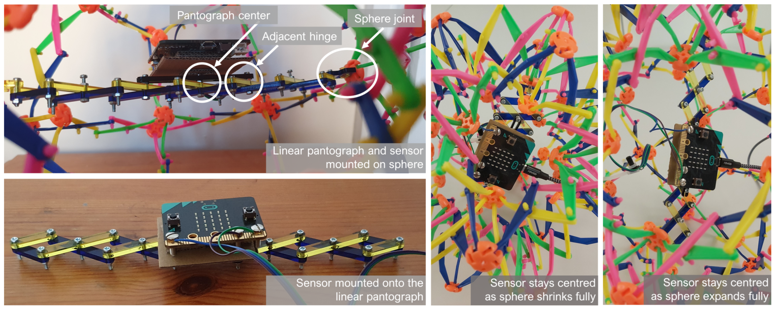
3.2. Sensor Mounting

The potentiometer used to detect the shape state can be attached to any of the SLEs, and the change in shape state then becomes trivial to detect. The mounting of the tri-axis accelerometer/magnetometer presents another interesting design challenge. The sensor chip is integrated onto the micro:bit board, and thus the challenge is to mount the micro:bit board. Once again, while an external optical tracking option is technologically feasible, we sought a “self-contained” solution. The best position for the sensor to sense rotation-based manipulation is at the centre of the Hoberman sphere. Thus, the challenge was how to mount the sensor that remained at the centre of the sphere irrespective of the shape state changes the sphere is subjected to. In an early prototype, we used a pair of orthogonally arranged telescoping rods and placed the sensor at the intersection of the two, which also coincided with the centre of the Hoberman sphere. However, the force needed to manually actuate the telescoping rods is a lot greater than the force needed to manipulate the Hoberman sphere itself. We eventually selected a design that relies on a pantograph structure consisting of linear SLEs (see Figure 4). The linear SLEs were designed such that their controllable parameter (length) corresponds linearly to the controllable parameter (diameter) of the Hoberman sphere. We then attached the pantograph structure to a pair of diametrically opposite four-way link joints of the Hoberman sphere. This allowed the change in diameter of the Hoberman sphere to be reflected in the shape state of the pantograph structure. A critical design requirement is that the pantograph structure should have an odd number of hinge joints. If there are an odd number (2n + 1) of hinge joints, irrespective of the shape state, the mid-point of the structure coincides with the (n + 1)th hinge joint. A sensor attached to this hinge joint will always stay at the centre of the Hoberman sphere. A single sliding link running to adjacent hinge joints of the pantograph ensures that the rotational DoF of the micro:bit is fully constrained and tightly coupled to the sphere DoFs.

3.3. Software Implementation

We used a simple software architecture to connect the HoberUI device to a connected application. A simple serial communication scheme transfers the sensor data to a middleware application running on a Windows 10 machine. The middleware then communicates the input events to any connected application that uses the HoberUI device.

Input Processing

The computational power required to convert the sensor readings into input is obtained from the machine running the middleware. The micro:bit is only responsible for reading and transmitting the raw sensor data to the middleware. The micro:bit runs a MicroPython script that performs all sensing functions. At start-up, a calibration routine is performed. After this, the micro:bit periodically transmits data to the middleware over the USB connection. The serial USB can be easily replaced by Bluetooth or micro:bit radio connectivity. The following data are transmitted by the micro:bit to the middleware: raw accelerometer and magnetometer readings, the sphere’s diameter as a normalised value and a binary flag indicating whether a pulse gesture was performed. The middleware is implemented in Python. The sensor streams are run through a low-pass filter [44] to reduce noise in the data and then used to compute the rotation quaternion. This process also checks for the presence of a heave gesture. If present, the direction vector of the gesture is also computed. The middleware also runs a web-socket server which serves the processed status (rotation, heave) and raw (diameter, pulse) data through an endpoint to any client that requests it.

4. Interacting with HoberUI

The HoberUI device has several possible physical interactions: (1) it can be rotated like a the sphere around any of its axes; (2) it can be heaved in any direction in space; (3) it can be shrunk down to its smallest possible size or expanded fully. These physical interactions are used to populate a set of interactive inputs that can be achieved using the HoberUI device. These interactive inputs are presented in context with a sample application use case, which is exploring the solar system in a 3D environment, to help explain the rationale behind interactive choices.

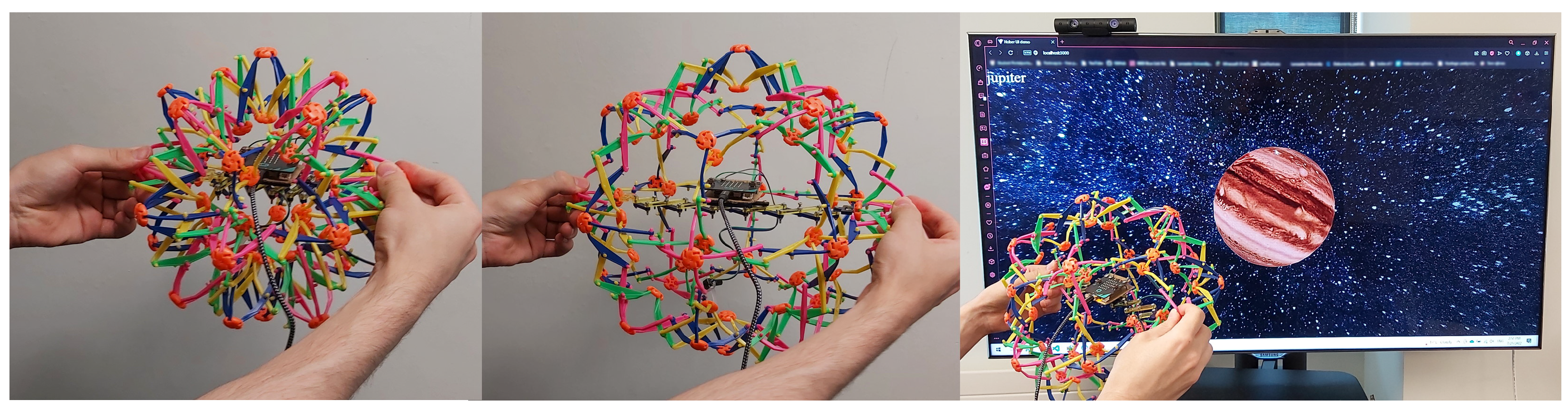
4.1. Mapping Physical Action to 3D Environments

The interactions available with HoberUI can be seen in Figure 5. Since the HoberUI structure has a spherical shape, rotating or moving the sphere can be intuitively identified as input. As a kinematic structure, HoberUI can shrink or grow (i.e., scale), thus exposing an additional input modality. This input modality can also be repurposed for input behaviour with binary states, e.g., button presses or activating menus, by considering short pulsed changes to size as an independent modality in action.
The rotation and scaling actions performed on the HoberUI device can be mapped to inputs that rotate and scale a target object one-to-one. However, this one-to-one mapping has limitations due to the physical constraints of the device for scaling and the physical action required to continue a rotation. Instead, we opt for an alternative scheme that uses the steering wheel metaphor [45,46]. Rotating the device initiates rotation of the virtual target, and the rate of rotation is controlled by the angle of rotation as measured from the starting position. Similarly, shrinking the device down produces a scaling rate, which continues to shrink the virtual target until the device is returned to the starting position.
Since the sensors on HoberUI do not support absolute position detection, translation is mapped to the heave gesture. The heave gesture can be described as follows. The HoberUI device is rapidly moved in a desired direction in a short burst and then stopped. There is no constraint on the direction of movement, and the application determines whether the heave gesture is treated as a valid interaction or not. The only restriction is that once the movement associated with the heave gesture is started, the movement has to continue in that direction only until the heave gesture is completed.
The middleware generates a heave event and provides a unit vector in the direction of the heave. The connected application can interpret this as translation in that direction or use it to navigate menus laid out in a 2D grid.
To implement a binary action like selection or clicking, we adapted the scaling behaviour to generate a “pulse” gesture. The pulse gesture is achieved by rapidly expanding or shrinking the HoberUI device from a rest state and then reversing the action to return to a scaling state similar to the original rest state. We can differentiate between the standard scaling action and the pulse gesture since the former results in scale change that has a smooth and sloped curve, while the latter has the profile of a short pulse. The pulse event can be interpreted by the connected application as a selection/click action. The pulse gesture is used in lieu of additional instrumentation of the device to include push buttons. Buttons/touch pads are well understood input controls. However, there are limited placement positions for such interface elements on the Hoberman sphere. The addition of buttons/touchpads defeats the purpose of the isokinetic nature of the HoberUI device, which allows it to be held and re-oriented in any way preferred by the user. The device does not have an absolute “up” orientation and can be used without any re-orientation between uses. Thus, the pulse gesture presents an interesting alternative to button elements as it is independent of the orientation of the device and is rather tied to the change in shape state of the kinematic structure.

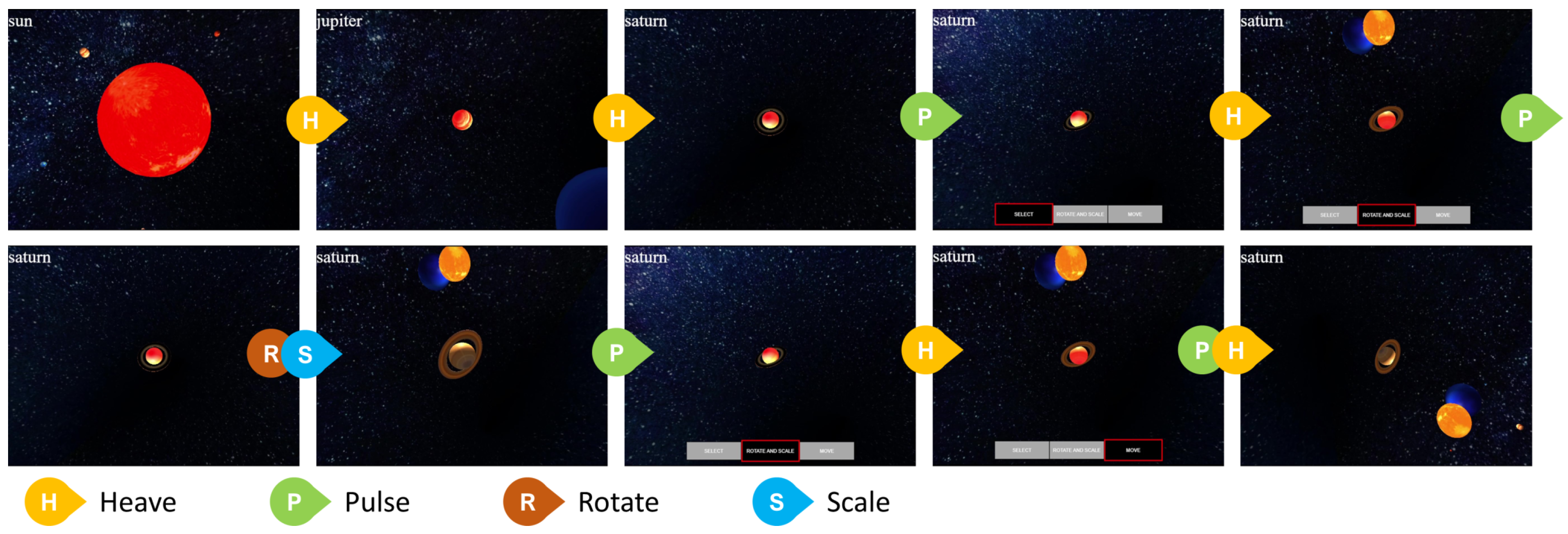
4.2. Solar System Demostrator Application

We implemented a browser-based application to investigate the user experience of interacting through the HoberUI input interface. The application allows a user to explore the solar system using an interactive 3D environment (Figure 1). The user can navigate through the solar system, selecting individual planets and interacting with them to view additional information about them. The application is built in JavaScript using the Three.js library and served via a Node.js server. The browser app connects to the middleware’s web-socket server as a client to receives the input event streams. The browser app uses the input events to manipulate the 3D environment and relies on a context-state model to determine how an input event is handled (see Figure 6).
We use the pulse gesture as a trigger to open a context selection menu in the application. The same gesture is also used to exit the context selection menu. Menu navigation and menu-item selection are achieved using the heave gesture. If the user enters the object-manipulation mode, the heave gesture is used to iterate through a set of targets visible on the screen. Once selected, the heave gesture moves the target. The target stops moving once a heave gesture in the opposite direction is performed. The rotation of the HoberUI device in object-manipulation mode is mapped to rotation of a target like a planet. Similarly, the scaling events are applied to the size of the target. If the user is in a perspective mode, the rotation is applied to the user’s perspective view of the solar system. Similarly, the scaling events affect the perspective. This approach covers the basic actions expected within a 3D environment [47]. It is also possible to combine rotation, scaling and translation interactions in a pair-wise manner. Hence, a target can be rotated and scaled at the same time. The user can exit an active mode at any time by performing a pulse gesture.

5. User Study

The aim of the user study was to understand users’ experiences with deployable structures as input devices. We adopted a qualitative approach, utilizing HoberUI and the solar system demonstrator application as elicitation tools. We gathered qualitative feedback specifically related to the task-driven user experiences.

5.1. Participants

Twelve participants were recruited for the study. The participants were recruited from students and staff of Lancaster University through convenience sampling. The participants (six male and six female) were between the ages of 19 and 34 years (mean 23.9 years, std. dev. 4.8). Six participants indicated awareness of tangible interfaces including controllers for VR headsets. The participants were not compensated in any monetary way for their time. The study was carried out after following standard procedure for ethical approval within the university.

5.2. Procedure

Each participant was briefed on the basic interactions they could perform with HoberUI and what actions was mapped to in the solar system demonstrator application. The participants were allowed to familiarize themselves with the interactions, viz., rotate, scale, heave for object manipulation and pulse for triggering/exiting the menu. They were then asked to complete four tasks, one after the other. The tasks were as follows:
  • To rotate and scale the solar system;
  • To make the planet Uranus the size of the Sun or bigger;
  • To simulate a Solar eclipse by moving the Earth so the moon blocks the sun;
  • To move the planet Neptune closer to the Sun.
After completing the tasks, we interviewed each participant individually. We gathered qualitative feedback around the following four themes: (1) how they found the experience overall; (2) what they found the easiest and hardest to achieve; (3) what they thought was missing or unnecessary about the device or demonstrator and (4) what they thought about the device being used in an everyday setting to work with a 3D environment or to be used for other applications. We also asked the participants to rate two factors on a Likert Scale: The perceived difficulty of using HoberUI (1—Very easy, 5—Very hard) and its intuitiveness (1—Not at all intuitive, 5—Extremely intuitive). The experiment lasted between 20 and 35 min on average, and we did not place time restrictions on the participants’ use of the application.

5.3. Data Analysis

We collected the comments from the participants in a written format. We also added the observations from the experimenter for each participant in a written format. We then used thematic analysis to analyse the qualitative results. We collected 144 textual chunks, which were analysed and generated 85 codes. We then formed themes that are presented in the following results section. We also finish by discussing the results of the Likert scale.

5.4. Results

We extracted four main themes that correspond to the following topics: overall impression of the devices; physical properties of HoberUI; UX of physical features mapping to virtual actions and suggestions for improvements and alternatives.

5.4.1. Overall Impression of the Device

The participants were positive about HoberUI. Eleven participants mentioned that they felt it was a “fun” and “interesting” device. P12 thought it was a “unique” concept and thought it felt like a game; and P8 expressed that it allowed them to be “immersed” in the task. Only one participant, P5, felt it was “frustrating”. Through further analysis, we saw that the participants had difficulty with the mapping, and P5 expressed that this was the causes of their frustration. Overall participants were positive and receptive to the introduction of a very different tangible form factor, which is rather inspiring for further development of HoberUI.

5.4.2. Physical Properties of HoberUI

Eight participants mentioned that they liked the physicality of HoberUI, e.g., P2 liked “how the physical action [on the HoberUI] mapped directly with the virtual world” and P7 said it is “extremely useful to look at alternative ways of interaction” particularly detailing further that “[HoberUI] is a really good start and has a lot of advantages for tangible interfaces”. P10 and P11 particularly mentioned the shape of HoberUI, saying that its spherical shape had many advantages for interaction and could expand interaction style. Digging further into the advantages of the deployable structure, P8 particularly liked the scaling gesture because “HoberUI has physical limitations on scaling so the user cannot expand it or shrink it as much as they want”. The physical constraints of the structure thus provide haptic feedback in the form of physical stops or constraints to the end user for better perception of their control input.
Another type of comment we observed related to how the participants handled/ grasped the HoberUI device, e.g., we found it interesting that P12 tried to keep their hands at the same place on the device while rotating it, instead of changing grip. P12 explained that “they did not feel like changing their hold on the HoberUI … did not want to accidentally change how it was moving or get confused with the hand positioning”. A clutch was also mentioned by P7. The “clutch” metaphor here relates to Buxton’s State-0 [48], allowing the users to stop the HoberUI device from tracking a specific input state without returning the orientation to a null or starting state.
P8 struggled to hold the HoberUI device fully deployed at all times and thus squeezed it most of the time to achieve a better grip. P7 also used the table to rest the device during interaction, and P2 mentioned that the device requires both hands at all times, which could be a bit inconvenient. In parallel, P9 like the fact that many muscles were involved during the interaction and thought it could be used for exertion games. The other participants did not mention any issues with the physical actions. P5 and P10 were negative about the device and wondered in what way HoberUI would be beneficial as compared to traditional controllers (e.g., mouse and VR controllers). P10 thought HoberUI was “fiddly” but indicated that this was mainly due to the nature of the prototype which is not quite as robust as a commercial controller.
Overall, this feedback shows that there are interesting elements with HoberUI and its particular tangible shape which provide unique features. This is a common challenge faced by any shape-changing input controller, and, like prior work, we do not expect it to be a replacement for traditional controllers. Rather, it offers uniquely specific ways of interacting with different content (and we will see in Section 5.4.4 some other ideas participants gave us).

5.4.3. UX of Physical Features Mapping to Virtual Actions

We observed that almost every participant found a specific interaction easier, and they completed those tasks quicker in comparison with the tasks that needed interactions that they were not naturally good at. Interestingly, our specific implementation could not be attributed to a particularly bad experience with a specific interaction or action. Instead, we saw that some participants were innately better at performing specific interactions. This could be attributed to each individual’s unique hand–eye coordination skills and intuition. The participants took some time to familiarize themselves with the usage of the device. At first, all participants performed the heave interaction as a big motion, which was not interpreted as heave by our implementation. One reason for this is the interpretation of the heave action, which is closer to a flick as implemented but thought to be closer to a throwing action by the users. However, they were subsequently able to perform the intended gesture easily. They also took time to understand how the virtual directions mapped to the real device. This is due to the implementation of the application rather than the controller itself. There was not a single consistent way the users mentally mapped the virtual axes within the application to the real world. Again, identifying the mapping took some exploration but was intuitively discovered by the users. In the same fashion, they ended up fully expanding and contracting the HoberUI device when performing the pulse interactions. As HoberUI is a novel interactive device, an initial learning curve is expected. The important observation was that the users adapted very quickly to the input methods, adjusting their movements for each interaction after discovering the optimal amount of input needed to perform the specific interaction.
Seven participants experienced challenges when trying to select a menu option or a specific planet with the heave interaction, while the others found the device easy to use. One observed cause with some participants was that they unintentionally manipulated the HoberUI device in such a way that the system detected both a heave gesture and a pulse gesture, resulting in behaviour that was not expected by the user.
Overall, there is scope for improvement in the robustness of tracking. In addition to this, the heave–pulse confound showed that user behaviour can sometimes lead to two unrelated actions to be performed, triggering unexpected input; while the users were able to recover from these errors, some of them expected and suggested adaptations that were more in line of the commercial state of the art.

5.4.4. Suggestions for Improvements and Alternatives

Participants proposed suggestions for the artefact, the visual interfaces and other application of HoberUI. For the HoberUI device, P1 and P11 both suggested the addition of buttons to the device as such “A clutch interaction like a button could be added and tactile feedback for the scaling interaction so it is clear where the middle point is where the object is not being scaled”. We thus need to design for a quick gesture that allows users to disengage mid-interaction. Such an interaction, for example, a pulse-like gesture for rotation, could be used in conjunction with the active gesture to exit the active interaction. P10 mentioned that HoberUI could be self-actuated to convey the scale of a system back to the user. Bi-directional feedback generated by self-actuation is a feasible feature as shown with SPATA [49] and FreeD [50]. This kind of self-actuation can be implemented for the HoberUI device. The scale feedback can be achieved by using a servo motor to actuate any one of the SLEs of the sphere or even the pantograph mount for the sensor. Three participants proposed improvement for the interfaces, but what was particularly interesting was that they wanted additional functionalities, such as looking at the history of the action or the ability to undo/redo. This would require additional mapping or external buttons to trigger those actions. P1 mentioned it would be fun to have a “portable” HoberUI to be “used every day” as a companion to conventional devices.
In term of possible applications, P2, P10, P11, P9 and P7 mentioned that the device would be appropriate for virtual reality or augmented reality contexts, and P8 thought it could be even used for a 3D environment in general (e.g., Blender). P9 and P10 proposed that the device could be a collaborative tool. Particularly, P9 imagined that “it could also store the transform data and could be used as a device to transfer it”. The idea was that the HoberUI device would allow different users to explore and experience the dimension and scale of the data, extending the role of the HoberUI device beyond an input controller and as a data visualization device.
P11 and P12 found that “they could see it being used for educational purposes for children because it is based on physical movement”. (P12) or that the device could be used in a “museum exhibit” (P11). A similar concept was proposed by P10: “it could be used for protein exploration in biology to grasp concepts…[or] showcase molecular models”. They noted that a 3D input system attached to a 3D environment made it easier to interact with the 3D environment. While we chose the solar system application as a demonstrator with wide subject-matter familiarity and explored limited scenarios within, the participants were inspired by HoberUI and came up with various opportunities within many different contexts and scenarios. We think this is inspiring for future directions.

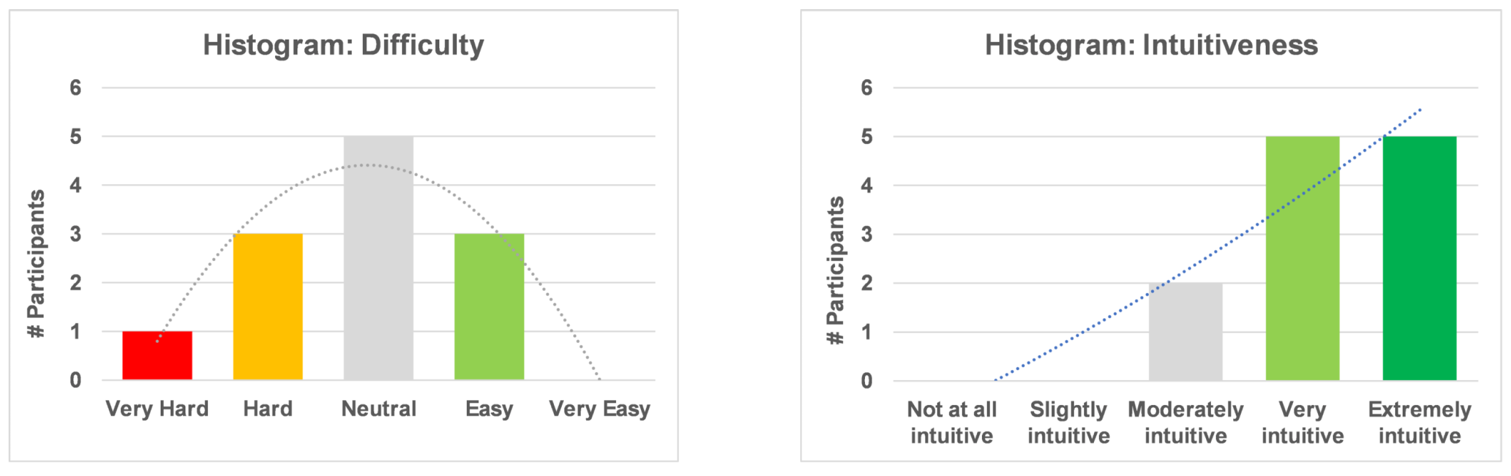
5.5. Likert Scale Results

The responses to the Likert scale questions of ease of use and intuitiveness revealed interesting results. Nearly half the participants indicated neutral preference for the ease of use, finding it neither difficult nor easy to use. Figure 7 shows a near-normal distribution for the responses. On the other hand, the participants were more positive about their interpretation of its intuitiveness. There is a strong skew towards responses that indicated high levels of intuitiveness.

6. Discussion

6.1. Limitations

The HoberUI device described in this paper has its limitations. As a prototype, it has high fidelity with respect to its shape-change behaviour. However, as mentioned by users, the overall sensing system leads to some limitations such as lacking proper, high-refresh-rate, 6-DoF sensing with absolute positioning. These limitations are primarily driven by the use of ultra-low cost sensing methods. The system could potentially benefit from the addition of touch/contact surfaces and even input buttons. However, the HoberUI design approach intentionally avoided adding buttons (e.g., sensing two button inputs on a micro:bit is already available) as these would distract from a proper exploration of how the shape state could be used to create an interesting set of interactive inputs.

6.2. Future Directions

6.2.1. Mini and Macro HoberUIs

The current design of HoberUI relies on a bimanual approach, and the size of the HoberUI controller is sized accordingly. It is possible to design for a form factor that fits in a single hand and configured for single handed use as shown in Figure 8. This form factor is analogous to Chinese Baoding balls. The actions of heave and pulse could be easily performed using hand movement and by using fingers to control the size of the HoberUI device. The miniature version can also be used in parallel with other standard input controllers like a stylus, wand or mouse. Some participants in the study suggested that HoberUI could be larger and used in public settings such as museums, and this could lead to some interesting usage that involves collaboration-based interactions.

6.2.2. Generalization to Other Applications

As stated in our evaluation, HoberUI can be applied to other application contexts like biology. This needs to be explored, and further work needs to be carried out to understand in which context HoberUI, or alternatively other kinematic structures, could be beneficial. We also need to further investigate the mapping between physical actions and virtual/digital features to enhance the intuitiveness of interactions or provide customised interactivity for individual users. Our work has a limitation in that it looks at the user experience through a qualitative lens, and further quantitative empirical studies could be performed to better understand the benefit of HoberUI or alternatives.

6.2.3. Generalization to Kinematic Configurations

The HoberUI device is built using the Hoberman sphere configuration, which is just one example of a deployable kinematic structure. It is possible to design for other kinematic structures. This can be application-dependent, like TubeMouse [32], where the kinematic structure can be designed to closely resemble the target objects within the application. Similarly, structures that mimic a specific affordance or behaviour can be implemented. The slider-knob concept demonstrated by Kim et al. [31] could be implemented using a kinematic structure. The process for designing bespoke kinematic structures is described by De Temmerman [51], and this can be used to design different pantographic configurations with additional features like reconfigurable plates.

7. Conclusions

We have investigated the use of a symmetrical spherical kinematic structure for controlling a 3D environment. We contributed HoberUI, a bimanual, tangible interface with 7 degrees of freedom and demonstrated its usage in interaction with an application scenario of exploring the solar system. Our qualitative user evaluation showed that there are many advantages to HoberUI, including its physical properties placing natural constraints on the interaction but also promoting bimanual usage and intuitive mapping with the 3D environment. We also discussed how HoberUI could be useful for other application scenarios such as museum exhibits, manipulation of molecular models in biology or even generic 3D objects. Finally, our results also reveal that the mapping between physical input and virtual ones requires further investigation.

Author Contributions

All authors have contributed significantly to the work. Conceptualization, G.R. and A.K.; methodology, A.K. and A.R.; software, G.R.; formal analysis, A.K. and A.R.; investigation, G.R.; resources, A.K., G.R. and A.R.; data curation, A.K.; writing—original draft preparation, G.R. and A.K.; writing—review and editing, A.K. and A.R.; visualization, A.K. and A.R.; supervision, A.K. All authors have read and agreed to the published version of the manuscript.

Funding

This research received no external funding.

Institutional Review Board Statement

The study was conducted after following the standard procedure for ethical approval for undergraduate student projects within the Faculty of Science and Technology, Lancaster University.

Informed Consent Statement

Informed consent was obtained from all subjects involved in the study.

Data Availability Statement

Data are available upon request from the corresponding authors.

Conflicts of Interest

The authors declare no conflicts of interest.

References

  1. Fenci, G.E.; Currie, N.G. Deployable structures classification: A review. Int. J. Space Struct. 2017, 32, 112–130. [Google Scholar] [CrossRef]
  2. del Grosso, A.E.; Basso, P. Deployable Structures. Adv. Sci. Technol. 2013, 83, 122–131. [Google Scholar] [CrossRef]
  3. Kent, E. Periodic Kinematic Structures. Ph.D. Thesis, Technion, Israel Institute of Technology, Haifa, Isreal, 1983. [Google Scholar]
  4. Mruthyunjaya, T. Kinematic structure of mechanisms revisited. Mech. Mach. Theory 2003, 38, 279–320. [Google Scholar] [CrossRef]
  5. Swaminathan, S.; Rivera, M.; Kang, R.; Luo, Z.; Ozutemiz, K.B.; Hudson, S.E. Input, Output and Construction Methods for Custom Fabrication of Room-Scale Deployable Pneumatic Structures. Proc. ACM Interact. Mob. Wearable Ubiquitous Technol. 2019, 3, 62. [Google Scholar] [CrossRef]
  6. Perovich, L.; Mothersill, P.; Farah, J.B. Awakened Apparel: Embedded Soft Actuators for Expressive Fashion and Functional Garments. In Proceedings of the 8th International Conference on Tangible, Embedded and Embodied Interaction, TEI ’14, Munich, Germany, 16–19 February 2014; pp. 77–80. [Google Scholar] [CrossRef]
  7. Lin, J.; Zhou, J.; Koo, H. Enfold: Clothing for People with Cerebral Palsy. In Proceedings of the 2015 ACM International Joint Conference on Pervasive and Ubiquitous Computing and Proceedings of the 2015 ACM International Symposium on Wearable Computers, UbiComp/ISWC’15 Adjunct, Osaka, Japan, 7–11 September 2015; pp. 563–566. [Google Scholar] [CrossRef]
  8. Roudaut, A.; Reed, R.; Hao, T.; Subramanian, S. Changibles: Analyzing and Designing Shape Changing Constructive Assembly. In Proceedings of the SIGCHI Conference on Human Factors in Computing Systems, CHI ’14, Toronto, ON, Canada, 26 April–1 May 2014; pp. 2593–2596. [Google Scholar] [CrossRef]
  9. Dias, M.A.; McCarron, M.P.; Rayneau-Kirkhope, D.; Hanakata, P.Z.; Campbell, D.K.; Park, H.S.; Holmes, D.P. Kirigami actuators. Soft Matter 2017, 13, 9087–9092. [Google Scholar] [CrossRef] [PubMed]
  10. Chang, Z.; Ta, T.D.; Narumi, K.; Kim, H.; Okuya, F.; Li, D.; Kato, K.; Qi, J.; Miyamoto, Y.; Saito, K.; et al. Kirigami Haptic Swatches: Design Methods for Cut-and-Fold Haptic Feedback Mechanisms. In Proceedings of the 2020 CHI Conference on Human Factors in Computing Systems, CHI ’20, Honolulul, HI, USA, 25–30 April 2020; pp. 1–12. [Google Scholar] [CrossRef]
  11. Zheng, C.; Oh, H.; Devendorf, L.; Do, E.Y.L. Sensing Kirigami. In Proceedings of the 2019 on Designing Interactive Systems Conference, DIS ’19, San Diego, CA, USA, 23–28 June 2019; pp. 921–934. [Google Scholar] [CrossRef]
  12. Kaspersen, M.H.; Hines, S.; Moore, M.; Rasmussen, M.K.; Dias, M.A. Lifting Kirigami Actuators Up Where They Belong: Possibilities for SCI. In Proceedings of the 2019 on Designing Interactive Systems Conference, DIS ’19, San Diego, CA, USA, 23–28 June 2019; pp. 935–947. [Google Scholar] [CrossRef]
  13. Neville, R.M.; Scarpa, F.; Pirrera, A. Shape morphing Kirigami mechanical metamaterials. Sci. Rep. 2016, 6, 31067. [Google Scholar] [CrossRef] [PubMed]
  14. Qamar, I.P.S.; Groh, R.; Holman, D.; Roudaut, A. HCI Meets Material Science: A Literature Review of Morphing Materials for the Design of Shape-Changing Interfaces. In Proceedings of the 2018 CHI Conference on Human Factors in Computing Systems, CHI ’18, Montreal, QC, Canada, 21–26 April 2018; pp. 1–23. [Google Scholar] [CrossRef]
  15. Bell, F.; Ofer, N.; Frier, E.; McQuaid, E.; Choi, H.; Alistar, M. Biomaterial Playground: Engaging with Bio-Based Materiality. In Proceedings of the Extended Abstracts of the 2022 CHI Conference on Human Factors in Computing Systems, CHI EA ’22, New Orleans, LA, USA, 29 April–5 May 2022. [Google Scholar] [CrossRef]
  16. Zheng, J.; Bryan-Kinns, N.; McPherson, A.P. Material Matters: Exploring Materiality in Digital Musical Instruments Design. In Proceedings of the Designing Interactive Systems Conference, DIS ’22, Virtual, 13–17 June 2022; pp. 976–986. [Google Scholar] [CrossRef]
  17. Roudaut, A.; Karnik, A.; Löchtefeld, M.; Subramanian, S. Morphees: Toward high “shape resolution” in self-actuated flexible mobile devices. In Proceedings of the SIGCHI Conference on Human Factors in Computing Systems, Paris, France, 27 April–2 May 2013; pp. 593–602. [Google Scholar]
  18. Rasmussen, M.K.; Pedersen, E.W.; Petersen, M.G.; Hornbæk, K. Shape-Changing Interfaces: A Review of the Design Space and Open Research Questions. In Proceedings of the SIGCHI Conference on Human Factors in Computing Systems, CHI ’12, Austin, TX, USA, 5–10 May 2012; pp. 735–744. [Google Scholar] [CrossRef]
  19. Kinoshita, Y.; Go, K.; Kozono, R.; Kaneko, K. Origami Tessellation Display: Interaction Techniques Using Origami-Based Deformable Surfaces. In Proceedings of the CHI ’14 Extended Abstracts on Human Factors in Computing Systems, Toronto, ON, Canada, 26 April–1 May 2014; pp. 1837–1842. [Google Scholar] [CrossRef]
  20. Lipton, J.; Chin, L.; Miske, J.; Rus, D. Modular Volumetric Actuators Using Motorized Auxetics. In Proceedings of the 2019 IEEE/RSJ International Conference on Intelligent Robots and Systems (IROS), Macau, China, 3–8 November 2019; pp. 7460–7466. [Google Scholar] [CrossRef]
  21. Ion, A.; Baudisch, P. Interactive Metamaterials. Interactions 2019, 27, 88–91. [Google Scholar] [CrossRef]
  22. Khalilbeigi, M.; Lissermann, R.; Mühlhäuser, M.; Steimle, J. Xpaaand: Interaction Techniques for Rollable Displays. In Proceedings of the SIGCHI Conference on Human Factors in Computing Systems, Vancouver, BC, Canada, 7–12 May 2011; pp. 2729–2732. [Google Scholar] [CrossRef]
  23. Khalilbeigi, M.; Lissermann, R.; Kleine, W.; Steimle, J. FoldMe: Interacting with Double-Sided Foldable Displays. In Proceedings of the Sixth International Conference on Tangible, Embedded and Embodied Interaction, Kinston, ON, Canada, 19–22 February 2012; pp. 33–40. [Google Scholar] [CrossRef]
  24. Ramakers, R.; Schöning, J.; Luyten, K. Paddle: Highly Deformable Mobile Devices with Physical Controls. In Proceedings of the SIGCHI Conference on Human Factors in Computing Systems, Toronto, ON, Canada, 26 April–1 May 2014; pp. 2569–2578. [Google Scholar] [CrossRef]
  25. Lee, J.C.; Hudson, S.E.; Tse, E. Foldable Interactive Displays. In Proceedings of the 21st Annual ACM Symposium on User Interface Software and Technology, Monterey, CA, USA, 19–22 October 2008; pp. 287–290. [Google Scholar] [CrossRef]
  26. Zhou, Y.; Sueda, S.; Matusik, W.; Shamir, A. Boxelization: Folding 3D Objects into Boxes. ACM Trans. Graph. 2014, 33, 71. [Google Scholar] [CrossRef]
  27. Goguey, A.; Steer, C.; Lucero, A.; Nigay, L.; Sahoo, D.R.; Coutrix, C.; Roudaut, A.; Subramanian, S.; Tokuda, Y.; Neate, T.; et al. PickCells: A Physically Reconfigurable Cell-Composed Touchscreen. In Proceedings of the 2019 CHI Conference on Human Factors in Computing Systems, Glassglow, UK, 4–9 May 2019; pp. 1–14. [Google Scholar] [CrossRef]
  28. Roudaut, A.; Krusteva, D.; McCoy, M.; Karnik, A.; Ramani, K.; Subramanian, S. Cubimorph: Designing Modular Interactive Devices. In Proceedings of the 2016 IEEE International Conference on Robotics and Automation (ICRA), Stockholm, Sweden, 16–21 May 2016; pp. 3339–3345. [Google Scholar] [CrossRef]
  29. Fröhlich, B.; Plate, J. The Cubic Mouse: A New Device for Three-Dimensional Input. In Proceedings of the SIGCHI Conference on Human Factors in Computing Systems, The Hague, The Netherlands, 1–6 April 2000; pp. 526–531. [Google Scholar] [CrossRef]
  30. Suh, J.; Kim, W.; Bianchi, A. Button+: Supporting User and Context Aware Interaction through Shape-Changing Interfaces. In Proceedings of the Eleventh International Conference on Tangible, Embedded, and Embodied Interaction, Yokohama, Japan, 20–23 March 2017; pp. 261–268. [Google Scholar] [CrossRef]
  31. Kim, H.; Coutrix, C.; Roudaut, A. KnobSlider: Design of a Shape-Changing UI for Parameter Control. In Proceedings of the 2018 CHI Conference on Human Factors in Computing Systems, Montreal, QC, Canada, 21–26 April 2018; pp. 1–13. [Google Scholar] [CrossRef]
  32. Geiger, C.; Rattay, O. TubeMouse—A Two-Handed Input Device for Flexible Objects. In Proceedings of the 2008 IEEE Symposium on 3D User Interfaces, Reno, NV, USA, 8–9 March 2008; pp. 27–34. [Google Scholar] [CrossRef]
  33. Roudaut, A.; Martinez, D.; Chohan, A.; Otrocol, V.S.; Cobbe-Warburton, R.; Steele, M.; Patrichi, I.M. Rubikon: A Highly Reconfigurable Device for Advanced Interaction. In Proceedings of the CHI ’14 Extended Abstracts on Human Factors in Computing Systems, Toronto, ON, Canada, 26 April–1 May 2014; pp. 1327–1332. [Google Scholar] [CrossRef]
  34. McClelland, J.C.; Teather, R.J.; Girouard, A. Haptobend: Shape-Changing Passive Haptic Feedback in Virtual Reality. In Proceedings of the 5th Symposium on Spatial User Interaction, Brighton, UK, 16–17 October 2017; pp. 82–90. [Google Scholar] [CrossRef]
  35. Feick, M.; Kleer, N.; Zenner, A.; Tang, A.; Krüger, A. Visuo-Haptic Illusions for Linear Translation and Stretching Using Physical Proxies in Virtual Reality. In Proceedings of the 2021 CHI Conference on Human Factors in Computing Systems, Yokohama, Japan, 8–13 May 2021. [Google Scholar] [CrossRef]
  36. Pellegrino, S. Deployable Structures in Engineering. In Deployable Structures; Springer: Vienna, Austria, 2001; pp. 1–35. [Google Scholar] [CrossRef]
  37. Hanaor, A.; Levy, R. Evaluation of Deployable Structures for Space Enclosures. Int. J. Space Struct. 2001, 16, 211–229. [Google Scholar] [CrossRef]
  38. You, Z.; Pellegrino, S. Foldable bar structures. Int. J. Solids Struct. 1997, 34, 1825–1847. [Google Scholar] [CrossRef]
  39. Hoberman, C. Radial Expansion/Retraction Truss Structures. U.S. Patent 5,024,031, 18 June 1991. [Google Scholar]
  40. Austin, J.; Baker, H.; Ball, T.; Devine, J.; Finney, J.; De Halleux, P.; Hodges, S.; Moskal, M.; Stockdale, G. The BBC Micro:Bit: From the U.K. to the World. Commun. ACM 2020, 63, 62–69. [Google Scholar] [CrossRef]
  41. Saidi, H.; Serrano, M.; Irani, P.; Dubois, E. TDome: A touch-enabled 6DOF interactive device for multi-display environments. In Proceedings of the 2017 CHI Conference on Human Factors in Computing Systems, Denver, CO, USA, 6–11 May 2017; pp. 5892–5904. [Google Scholar]
  42. Schmeier, B.; Kopetz, J.P.; Kordts, B.; Jochems, N. Manipulating Virtual Objects in Augmented Reality Using a New Ball-Shaped Input Device. In Proceedings of the 12th Augmented Human International Conference, Geneva, Switzerland, 27–28 May 2021. [Google Scholar] [CrossRef]
  43. Varesano, F.; Vernero, F. Introducing PALLA, a Novel Input Device for Leisure Activities: A Case Study on a Tangible Video Game for Seniors. In Proceedings of the 4th International Conference on Fun and Games, Toulouse, France, 4–6 September 2012; pp. 35–44. [Google Scholar] [CrossRef]
  44. Casiez, G.; Roussel, N.; Vogel, D. 1€ filter: A simple speed-based low-pass filter for noisy input in interactive systems. In Proceedings of the SIGCHI Conference on Human Factors in Computing Systems, Austin, TX, USA, 5–10 May 2012; pp. 2527–2530. [Google Scholar]
  45. Rekimoto, J. Tilting operations for small screen interfaces. In Proceedings of the 9th Annual ACM Symposium on User Interface Software and Technology, Seattle, WA, USA, 6–8 November 1996; pp. 167–168. [Google Scholar] [CrossRef]
  46. Kratz, S.; Rohs, M. Extending the virtual trackball metaphor to rear touch input. In Proceedings of the 2010 IEEE Symposium on 3D User Interfaces (3DUI), Waltham, MA, USA, 20–21 March 2010; pp. 111–114. [Google Scholar] [CrossRef]
  47. Bowman, D.A.; Kruijff, E.; LaViola, J.J.; Poupyrev, I. An introduction to 3-D user interface design. Presence 2001, 10, 96–108. [Google Scholar] [CrossRef]
  48. Buxton, W. A three-state model of graphical input. In Proceedings of the INTERACT ’90: IFIP TC13 Third Interational Conference on Human-Computer Interaction, Cambridge, UK, 27–31 August 1990; pp. 449–456. [Google Scholar]
  49. Weichel, C.; Alexander, J.; Karnik, A.; Gellersen, H. SPATA: Spatio-Tangible Tools for Fabrication-Aware Design. In Proceedings of the Ninth International Conference on Tangible, Embedded, and Embodied Interaction, Stanford, CA, USA, 15–19 January 2015; pp. 189–196. [Google Scholar] [CrossRef]
  50. Zoran, A.; Paradiso, J.A. FreeD: A Freehand Digital Sculpting Tool. In Proceedings of the SIGCHI Conference on Human Factors in Computing Systems, Paris, France, 27 April–2 May 2013; pp. 2613–2616. [Google Scholar] [CrossRef]
  51. De Temmerman, N. Design and Analysis of Deployable Bar Structures for Mobile Architectural Applications. Ph.D. Thesis, Vrije Universiteit Brussel, Brussel, Belgium, 2007. [Google Scholar]
Figure 1. HoberUI is a bimanual symmetric (6DoF + size) tangible interface with 7 degrees of freedom for manipulating based on a deployable structure that can change its scale. We demonstrate how it can be used to manipulate 3D environments, e.g., a virtual solar system.
Mti 08 00013 g001
Figure 2. Rigid-link kinematic structures based on linear and angulated SLEs.
Mti 08 00013 g002
Figure 3. (Left) Change in angle of SLE when open versus closed; (Right) potentiometer mounted as an auxiliary SLE.
Mti 08 00013 g003
Figure 4. Sensor mounting assembly. The sensor and micro:bit stay centred in position even if the sphere shrinks or expands.
Mti 08 00013 g004
Figure 5. HoberUI device inputs: Physical to virtual mapping for user inputs (from left to right): virtual object is rotated by rotating the device, scaled by shrinking (or expanding) device, hidden menu activated by pulse input, menu options iterated by heave input, menu closed with last iterated option chosen through another pulse input.
Mti 08 00013 g005
Figure 6. Sample interaction workflow for the task, “Scale, rotate and move Saturn”.
Mti 08 00013 g006
Figure 7. Ease of use and intuitiveness of HoberUI device.
Mti 08 00013 g007
Figure 8. HoberUI device miniaturised for single-handed use. (Left) manually expanded, (centre) default rest state, (right) manually compressed.
Mti 08 00013 g008
Disclaimer/Publisher’s Note: The statements, opinions and data contained in all publications are solely those of the individual author(s) and contributor(s) and not of MDPI and/or the editor(s). MDPI and/or the editor(s) disclaim responsibility for any injury to people or property resulting from any ideas, methods, instructions or products referred to in the content.

