1. Introduction
Elemental information allows for the identification of pigments in artworks and contributes to their understanding [
1]. Acquiring elemental distribution images is necessary as it provides representative information, as opposed to spot analysis [
2]. Chemical and elemental distribution images can reveal changes and hidden details invisible to the naked eye. Consequently, a number of methods have been developed and applied for the investigation of predominantly historical paintings, but also other art works and archaeological objects [
3,
4].
X-ray fluorescence spectroscopy (XRF) is one of these methods and allows for the acquisition of elemental distribution images by analyzing the X-rays emitted by a sample upon irradiation with a primary X-ray beam. The acquisition of these images is complicated by the fact that for X-rays, all materials feature a refractive index close to, but below, unity so that conventional lenses are not feasible. Consequently, the concept of photographic cameras cannot be directly transferred to X-rays. However, energy-dispersive X-ray cameras have been developed and used for the so-called full-field (FF)-XRF, making use of pinhole optics, polycapillary optics or microchannel plates [
5,
6,
7]. In FF-XRF, the sample is illuminated with a broad and intense X-ray beam to compensate for the lack of efficiency of the primary optic. This results in a high dose of primary radiation being absorbed in the sample and general concerns with radiation safety that limit on-site use.
The nature of X-ray optics renders the pixel-wise acquisition of images (whisk broom scanning) more practical than FF-XRF, as here, only a small area of the sample is illuminated at each moment, but a significant part of the emitted fluorescence radiation is recorded by detectors without lateral resolution. XRF imaging was first established in the form of µXRF, where microscopic distribution images are acquired. This was made possible by polycapillary lenses that feature a measured and simulated gain factor of more than 1000 compared to a collimator yielding an identical spot size [
8,
9]. Since 2008, macroscopic (MA)-XRF imaging has been established for the investigation of large (macroscopic) objects. Given the size of these objects, often a pixel size of ~1 mm is acceptable and simple collimators can be used instead of polycapillaries [
3,
4].
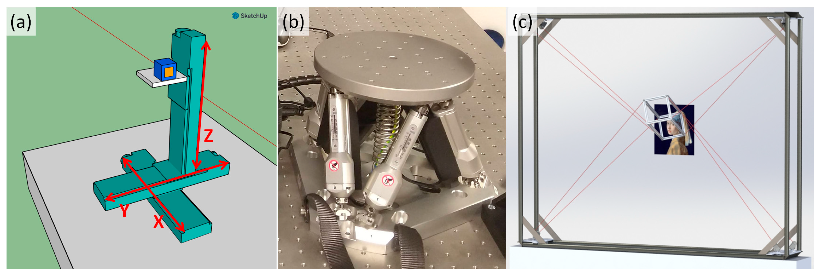
The whisk-broom scanning mode employed by µXRF and MA-XRF requires the movement of either a measurement head (X-ray source, optic and detector) or sample in a regular raster pattern. These scans are often performed “on the fly”, i.e., without stopping, and typically allocate an acquisition time of 10–500 ms to each pixel in the study of cultural heritage objects. The easiest way to realize this is to mount two linear motorized stages with a 90-degree bracket on top of one another and run them in two loops to acquire data for each pixel of the dataset with the measurement head mounted on the mobile platform of the second motor (see
Figure 1a). This approach is straightforward, as such linear motorized stages are available for end users by many manufacturers and are easy to control and include in data acquisition and control software [
10].
This approach works well, as long as the object can be assumed to be flat and is thus properly approximated by a two-dimensional movement. When a 3D object, e.g., a polychrome statue, is investigated with such a scanner, the data acquisition geometry changes with each pixel and images can only be obtained with spectral artefacts, which limits the acquisition of quantitative data, as detailed in the next section.
The simple two-dimensional scanner has two degrees of freedom, both lateral along the scanning direction. In order to keep a constant distance to a three-dimensional object, a third lateral degree of freedom is needed. This can be added by mounting the two-dimensional scanner on a third linear stage, as shown in
Figure 1a. This would alleviate many problems, but for an artefact-free acquisition of data, we would need to have the measurement head perpendicular to the surface of the object (see
Section 2). This can be achieved by mounting two rotation stages onto the scanner.
This sequential stacking of motorized stages into what can be called a serial robot is severely limited. The outermost motor, furthest away from the mobile platform, needs to hold and precisely move all motors above it, possibly requiring a stronger and heavier motor. Furthermore, any imprecision or vibration in the outer motors is enhanced throughout the system, making the position of the platform of the sample or scanner less precise than that of any component of the instrument. Thus, serial robots are well suited for operations with low degrees of freedom, but less so for holding a platform with more degrees of freedom.
An alternative to serial robots are parallel robots, where several actuators work in parallel to move a mobile platform, on which either the sample or measurement head are mounted. As these actuators work in parallel, they support one another in the positioning of the mobile platform and partially compensate for their imperfections. Variants commonly encountered in laboratories and factories are hexapods, where a mobile platform is held by six legs and moved with six degrees of freedom (see
Figure 1b).
A number of instruments have been presented that allow for the investigation of 3D objects via XRF. Early instruments combined a 3D serial motorized stage with a laser distance measurement device that kept a constant distance between the measurement head and the surface during a scan [
11]. Adapting a 3D printer has allowed for making (confocal) point measurements on 3D objects [
12]. While the travel range of a hexapod is too limited to be used as a platform during a conventional scan, mounting it as a final positioning device on a serial robot with three lateral degrees of freedom allows for the distortion-free acquisition of elemental distribution images via particle-induced X-ray emission (PIXE), which largely differs from XRF by replacing primary X-rays with charged particles in the primary beam [
13]. An FF-XRF system mounted on a robotic arm was described [
14].
We decided to explore the possibilities of a positioning system not used in spectroscopy so far, i.e., a cable-driven parallel robot (short-cable robot, see
Figure 1c). In the model shown, the mobile platform (center) is held by eight cables (red). It can be positioned in five degrees of freedom (three lateral and two rotational) through the coordinated deployment/retrieval of the cables. The platform can, with limitations, travel inside the frame of the cable robot and is, for the workspace it achieves, lightweight compared to other devices. On the other hand, the control of a cable robot is not straightforward. For precise positioning, the force applied on the platform by the cables needs to be precise, but as the cables are not rigid, a kinematic modeling of this is not straightforward. Further, it was uncertain how stable such a platform would ultimately be.
Figure 1.
(
a) Three-axis linear motorized stages, a serial robot; (
b) a hexapod stage, a popular parallel robot; and (
c) a cable robot, reproduced from Tempel et al. [
15].
Figure 1.
(
a) Three-axis linear motorized stages, a serial robot; (
b) a hexapod stage, a popular parallel robot; and (
c) a cable robot, reproduced from Tempel et al. [
15].
2. The Effect of Geometry on MA-XRF Measurements
XRF investigations have three relevant components: the excitation side from the source to the sample surface, the interaction with the sample and the detection side from the surface of the sample to the recording of a photon in the detector. Each spectrometer has a design detection geometry for which it is optimized and any deviation from this affects the signal recorded.
Two aspects of the geometry of a measurement are to be considered here: the working distance and the tilt of the surface compared to the instrument. A working distance larger than the design distance influences the excitation and detection side. It means that a larger portion of the primary radiation is absorbed on the path between the optic and the sample, so that less fluorescence radiation is excited in the sample. On the detection side, the larger working distance means that, next to increased air absorption, the solid angle of the detector gets smaller and so less photons are recorded. If one reduces the working distance, however, the signals would be expected to be enhanced as the absorption is reduced and the solid angle is seemingly enhanced. However, the recorded signal is dropping as the detector is positioned in a fixed geometry for the designed working distance. In addition, the detector is also generally collimated to reduce the partial detection of the incoming photons. Thus, the actual solid angle is shrinking and less signal is recorded. This is well understood and illustrated by measurements in
Figure 2. It is also possible to correct for the variation in the working distance if the response of the instrument is known and the distance can be estimated [
16].
The variation of the surface tilt is twofold; the primary radiation has a longer pathlength of the thin surface layers, so that the ratio of fluorescence lines is changed and the layer thickness is overestimated. Further, the pathlength of the fluorescence radiation leaving the sample toward the detector can be larger or smaller, affecting the strength of the recorded signal.
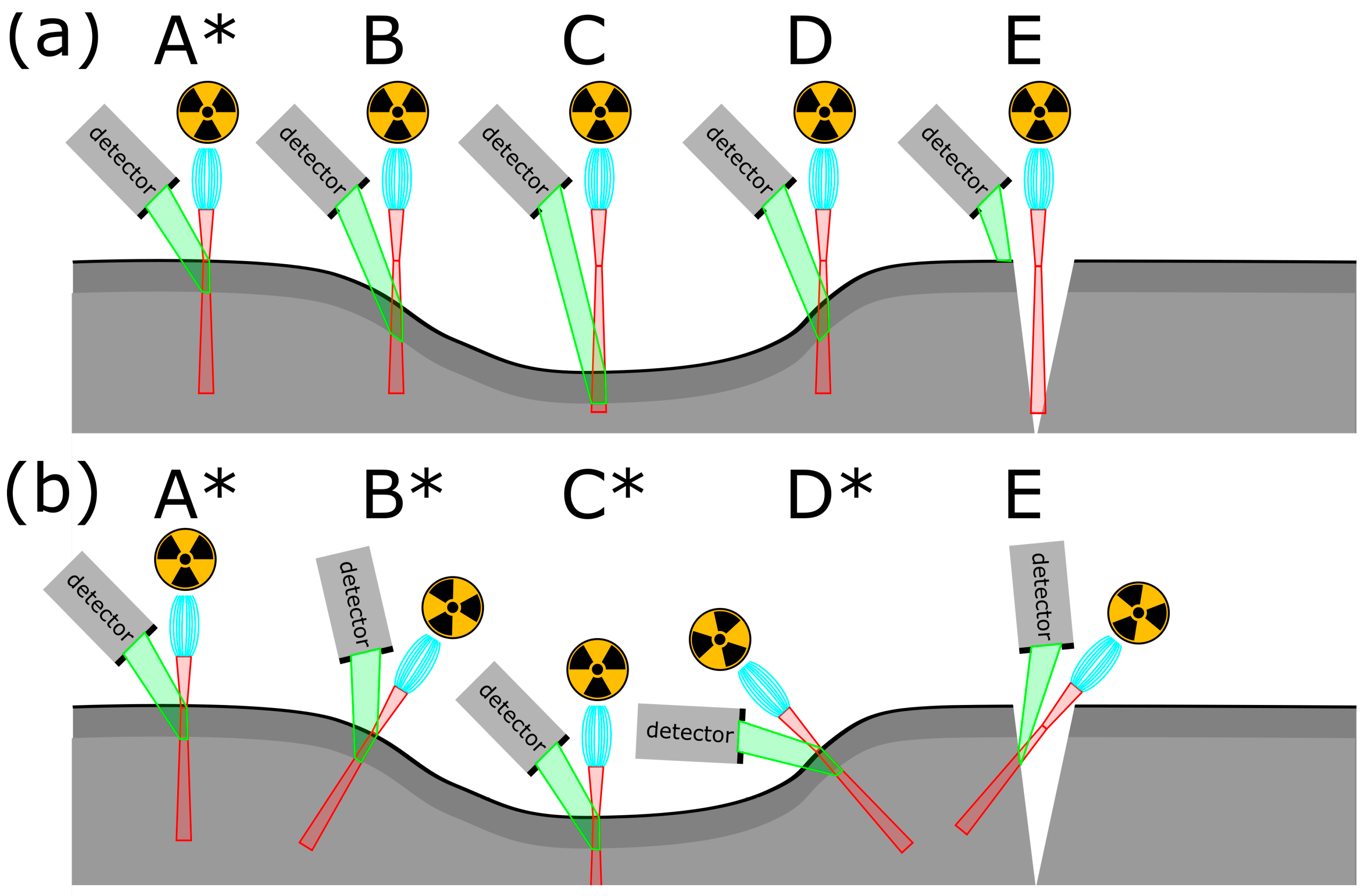
All these geometry effects are summarized in
Figure 3. In the upper part, A represents the design of the measurement geometry. C represents an enhanced working distance without a surface tilt. B and D represent an enhanced working distance with a surface tilt. As B is tilted away from the detector, the signal recorded would be weaker than that of D, where the sample tilts toward the detector. E represents a geometry where no fluorescence radiation would be recorded, as the path from the beam–sample interaction to the detector is blocked. The lower part of
Figure 3 shows the desired measurement geometry in that the instrument adapts to the surface in the cases A to D. In case E, no optimal geometry is possible, but a 3D MA-XRF scanner would allow for looking into the cracks of the surface and the sample sub-surface layers directly.
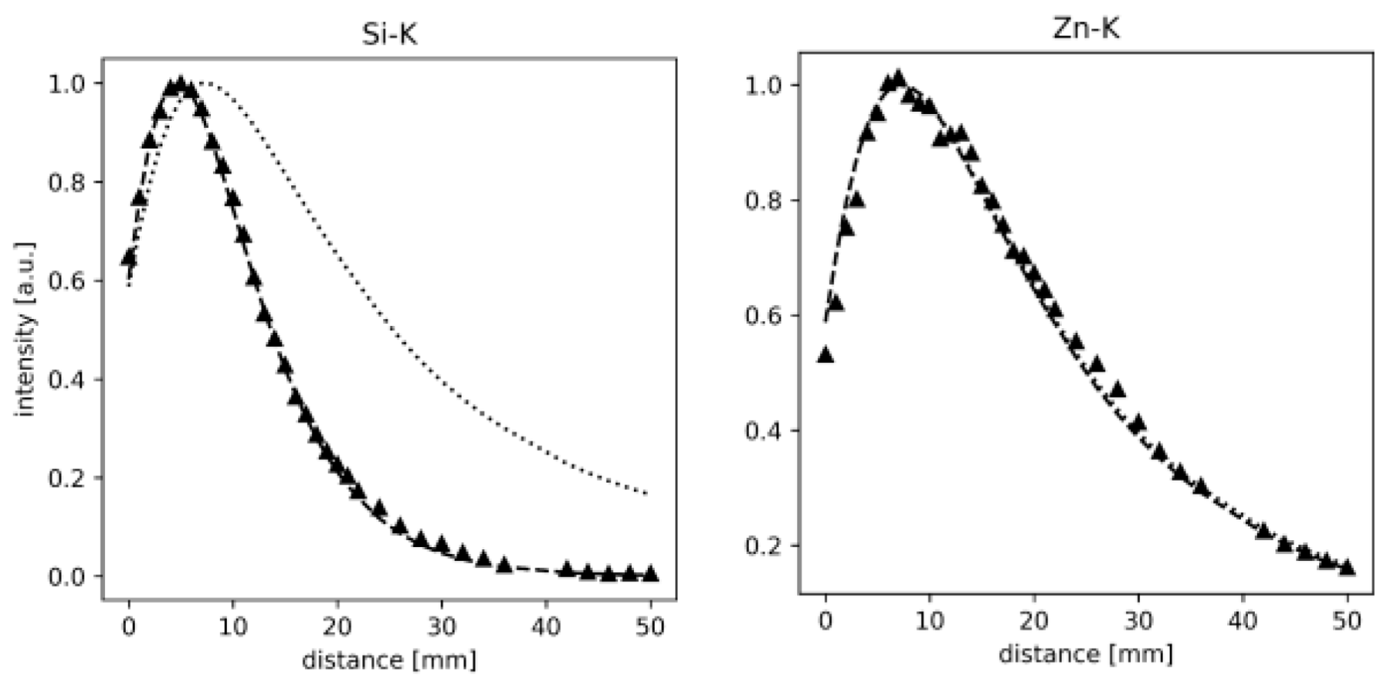
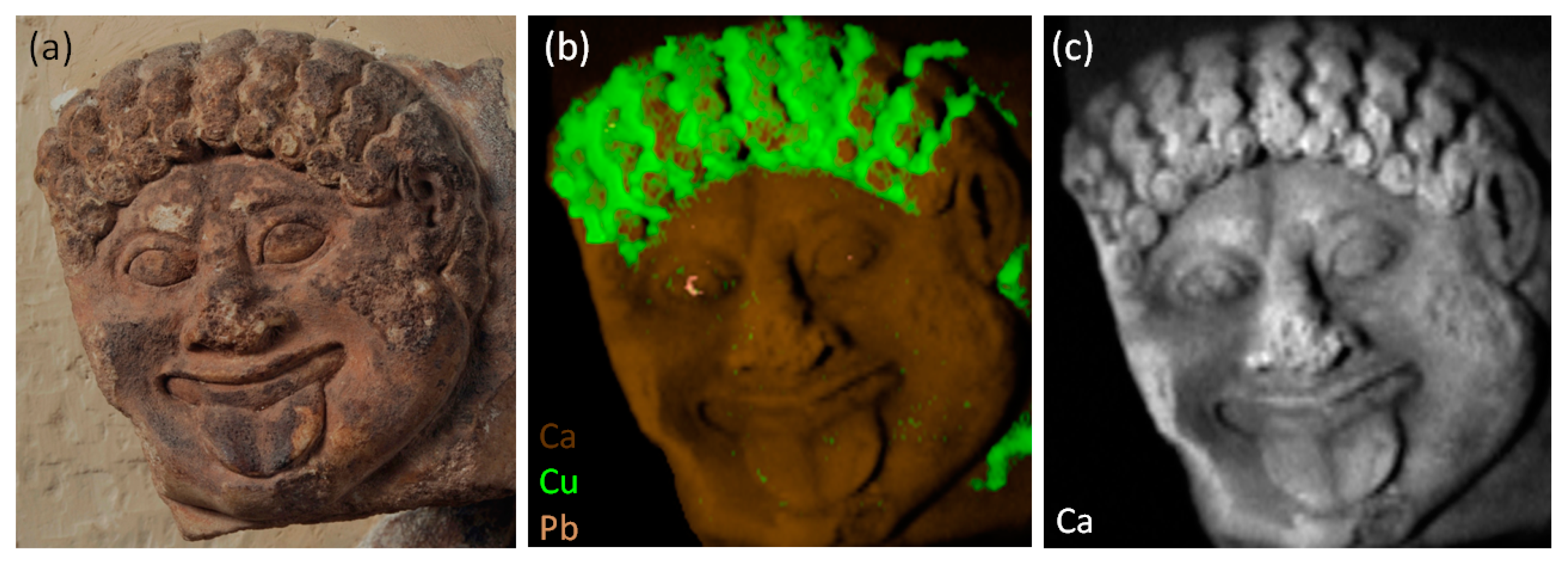
The effect of changing geometry in a real sample is shown in
Figure 4 on the example of a shield decoration (“Gorgoneion”) on the Frieze of the Siphnian Treasury (approx. 525 BCE) in the Archaeological Museum of Delphi, Greece. On the surface of the stone, remnants of pigments were found that are the only traces left of the original marvellous decoration of this piece. These are most likely a lead (Pb)-based white and a copper (Cu)-based green. These were unknown to exist prior to the MA-XRF investigations shown. But whether the brown surface of the stone was the result of a preparatory paint layer or a contamination during burial was an open question. The Ca signal, mostly resulting from the marble, would allow for identifying places with a layer covering the surface, and thus seeing if the absorbing brown layer is also present on broken surfaces. However, the recorded Ca intensity is strongly influenced by the geometry and only to a lesser degree by the presence of the absorbing layers on the surface. This renders the identification of the remnants of paint covering the surface close to guess work. In the original study, the problem was addressed by the fundamental parameter simulation of the investigation based on a photogrammetric 3D model of the Gorgoneion, but following the surface with a 3D instrument would have allowed for the acquisition of clear data to begin with [
17].
One problem that remains unaddressed in the MA-XRF imaging of 3D objects is that the footprint of the primary beam on the surface changes with the detection geometry due to surface tilt, and that all X-ray tube-based beams are ultimately divergent. While it does not seem impossible to correct for this, such an endeavor would likely also produce new interpolation artefacts [
16]. In fact, all the correction methods mentioned above produced additional artefacts, albeit not to a crippling degree. This could be avoided by proper 3D MA-XRF on a platform with at least five degrees of freedom.
3. The Instrument Design: CaRISA
In order to investigate the capabilities of cable robots as platforms for 3D MA-XRF imaging, we built a prototype and used our previously published design for a “Cable Robot for Inspecting and Scanning Artwork” (CaRISA) [
15]. In this publication, the kinematic model to control the robot is also explained in detail.
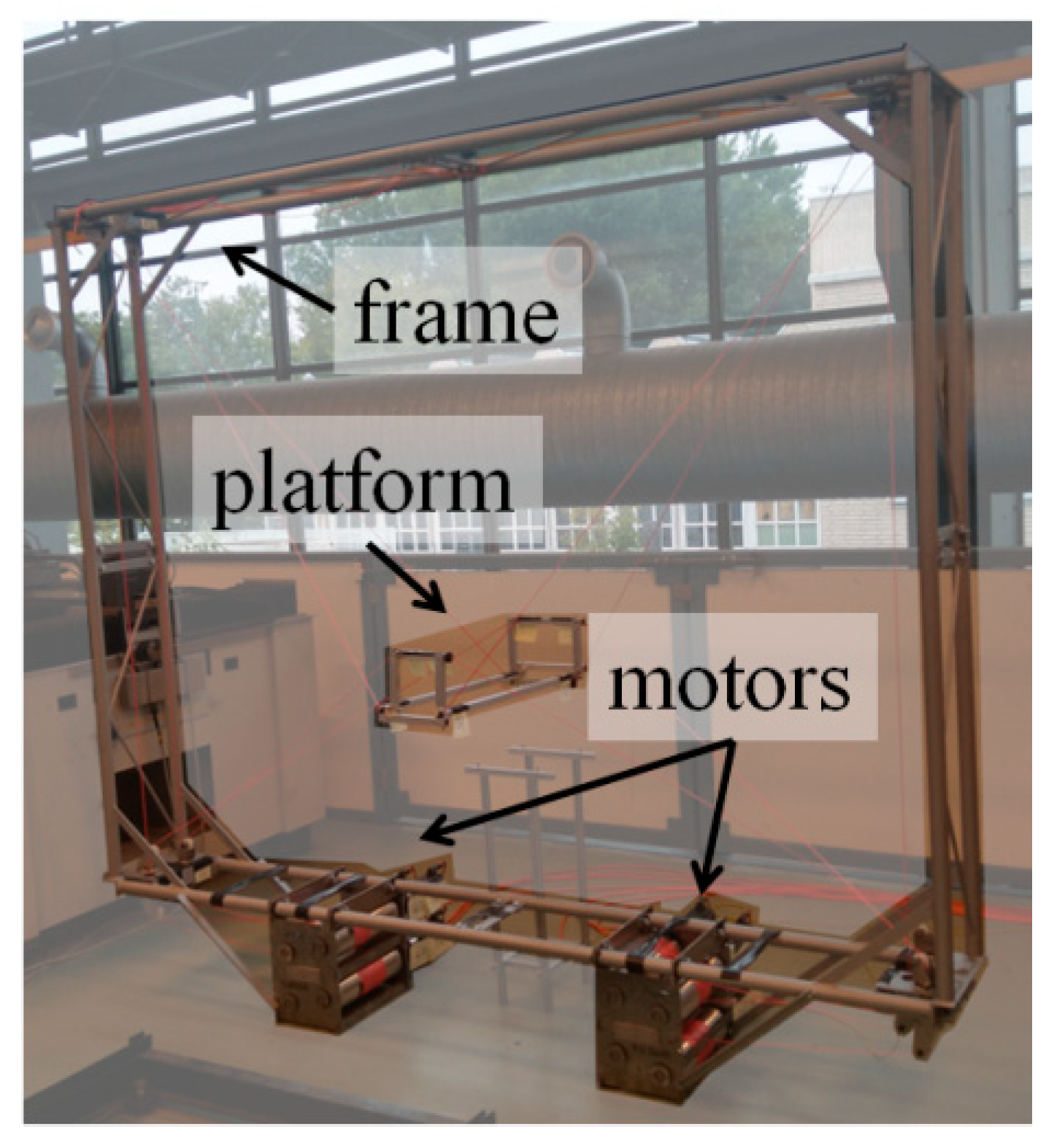
The instrument is shown in
Figure 5. The mobile platform is assembled from metal profiles, while the frame is assembled from four welded pieces. The eight polymer cables holding the platform are guided via rolls in the corners of the frame to eight winches below it that are connected to one servo motor, each with planetary gears. The motors are controlled via EtherCAT and an embedded Beckhoff PC. Disassembled, each part is less than 30 kg and can be carried by a single person without excess difficulty.
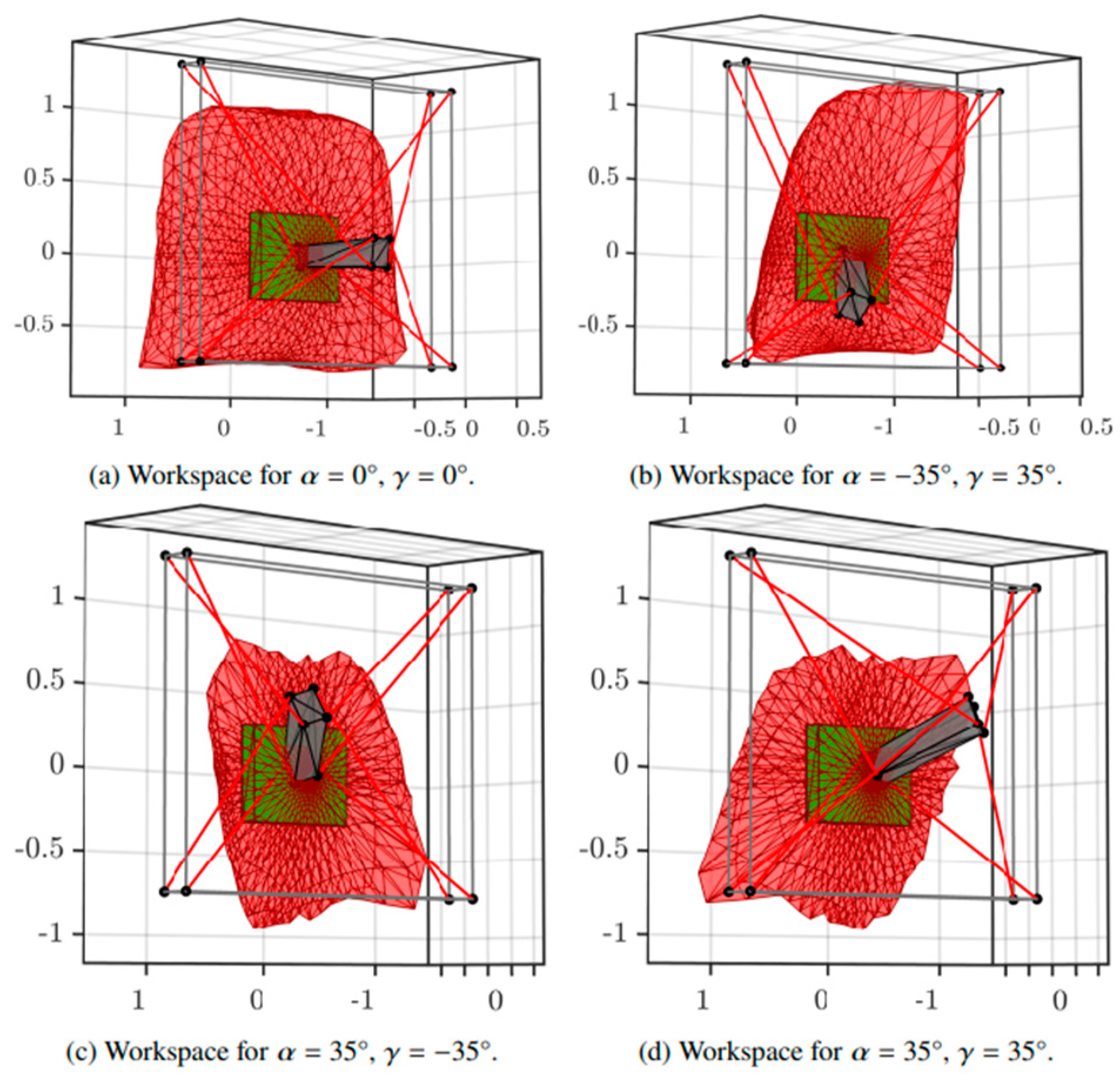
The frame has a dimension of 210 cm × 260 cm × 33 cm. The platform has a dimension of 20 cm × 18 cm × 75 cm. The design allows for a travel range of 150 cm × 100 cm × 30 cm while tilting the platform for up to 35 degrees with a payload of 5 kg. Due to the tension needed to be applied on the cables to position the platform in extreme positions, not all positions are achievable with all tilts. This is illustrated in
Figure 6, where the red hull shows the achievable positions with constant orientation as depicted by the gray platform cuboid; the green cuboid depicts an example desired workspace, e.g., a painting.
One concern could be the ripping of the cables and the platform swinging like a battering ram against the artwork; however, this can be excluded in case of CaRISA. This is an over-constrained system (more cables than degrees of freedom), so that even if a single cable tore, the uncontrolled movement of the platform would be minimal.
4. Tests
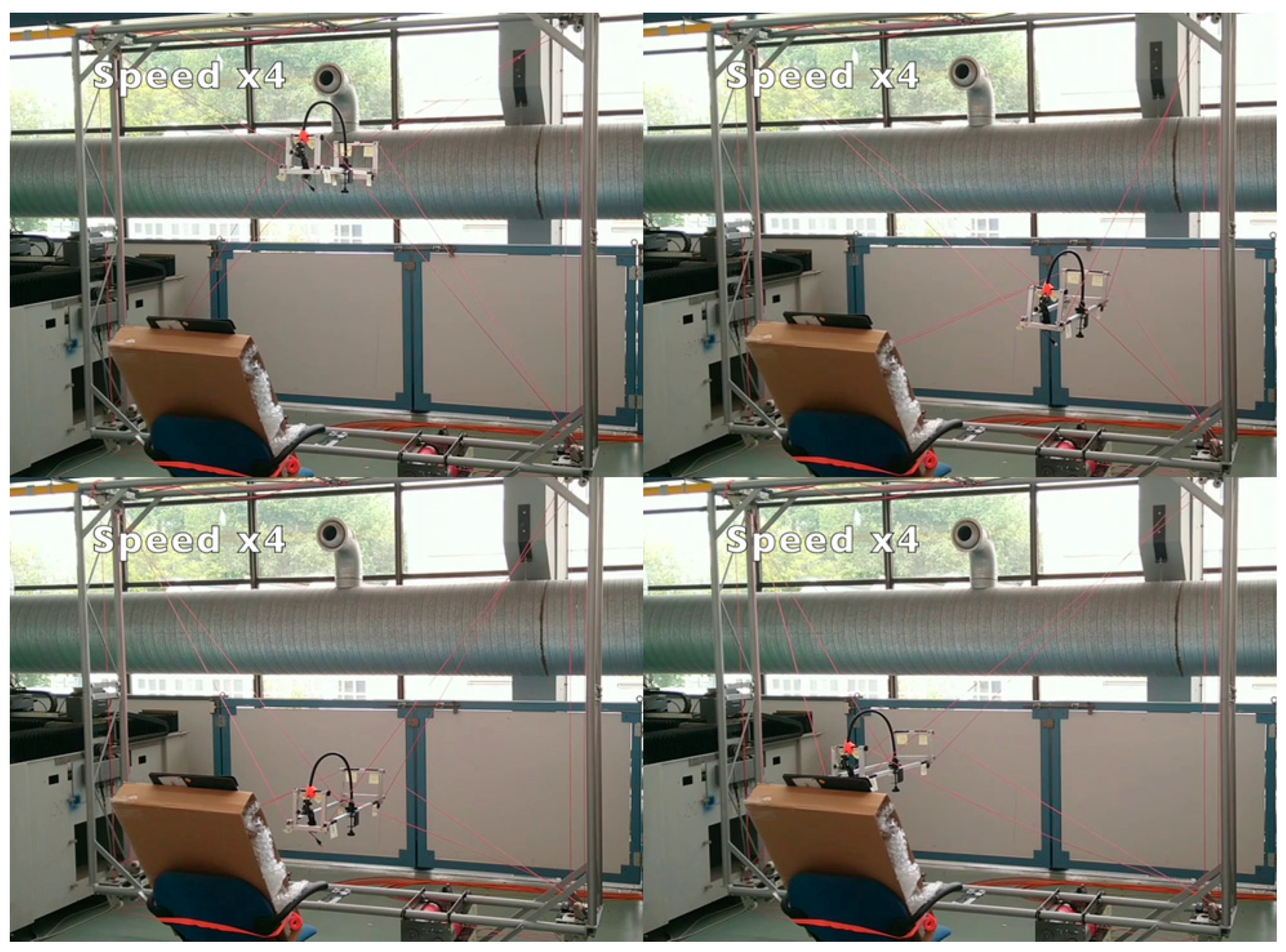
During the first test, we verified that CaRISA could hold a 5 kg payload and its range of travel was investigated. Here, extreme positions on the corners of the workspace were omitted in order to avoid tensions in the cables, resulting in the tearing or damages of the holders. A better characterization of the system and a proper kinematic model would also allow for exploiting these extreme positions. The range of movement of CaRISA is demonstrated in
Video S1, of which the stills of the extreme positions are given in
Figure 7.
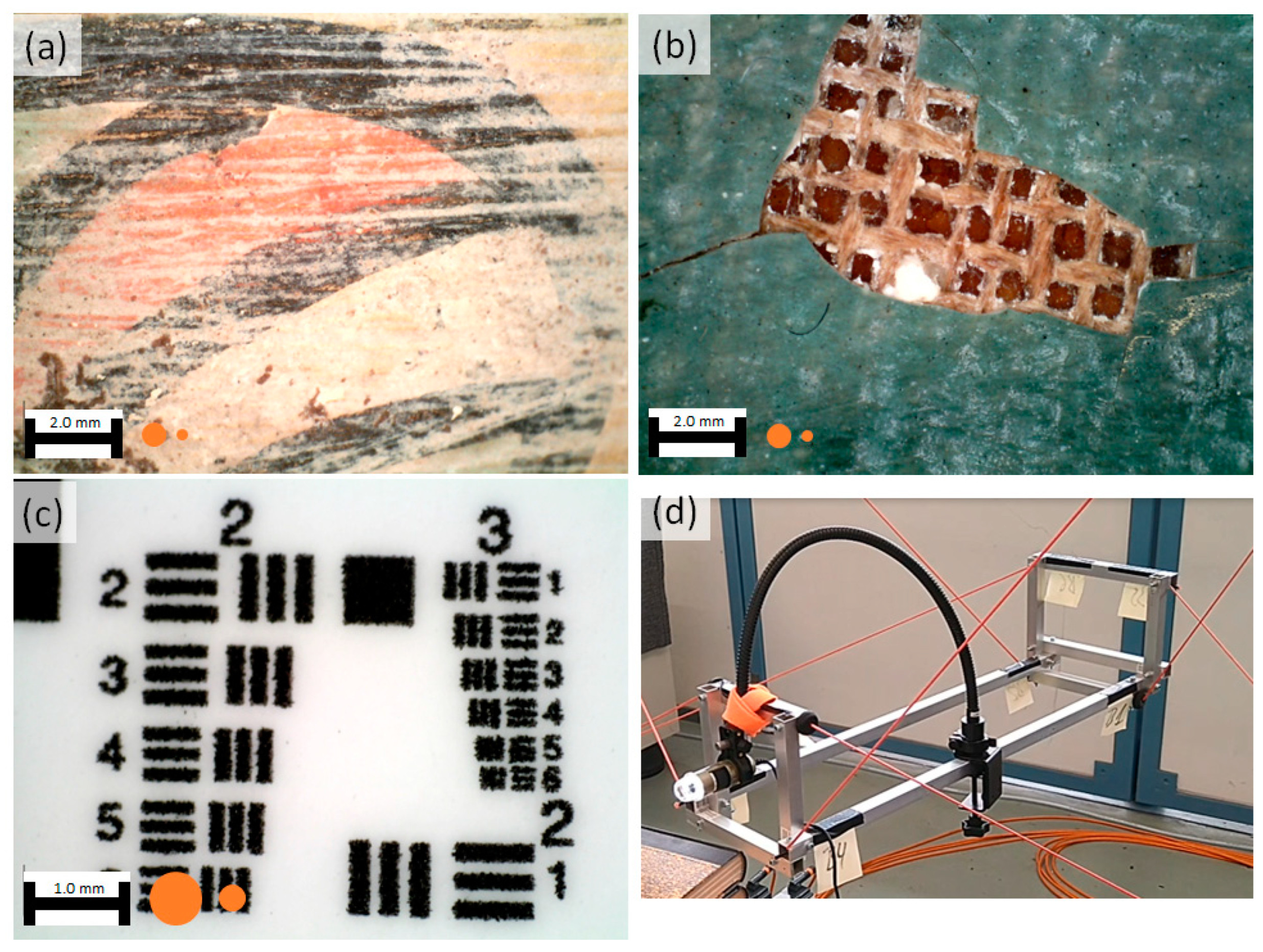
To simulate the MA-XRF measurement head, a Dinolite AM4113ZTL optical microscope was mounted on the CaRISA mobile platform (see
Figure 8d). This set-up was used to perform three additional tests. The CaRISA platform was moved in a semicircle around a painted pottery jug, keeping the surface in focus (
Figure 8a and
Video S2). In the second test, the measurement head was moved in parallel to a painting and then tilted to look inside a crack, similar to position E shown in
Figure 3 (
Figure 8b and
Video S3). As the mobile platform is not rotating around a virtual point but moving from one position to the next, the surface of the painting intermittently leaves the focus of the microscope. In a final test, a 1951 USAF resolution test chart (Edmund Optics, Nether Poppleton, UK) was scanned with variable speeds (
Figure 8c and
Video S4).
This first set of tests confirmed the range and flexibility that CaRISA offers, providing a large working space and a flexible approach to the sample. The tests on the 1951 Airforce test chart illustrate the remarkable stability of this prototype, having vibrations that are far below the beam size of a typical MA-XRF scan of 0.25–0.5 mm when resting and stopping. This stability is even more impressive, given that no damping was included in the current design, so that room for improvement is present. It also illustrates speeds up to 120 mm/min, which would correspond to a dwell time of 250 ms/pixel with a pixel size of 0.5 mm, IIh is a typical value, comparable to the data preseIted in
Figure 4.
While these experiments showed the potential of cable robots as platforms, they also showed some limitations. In the final test on the 1951 USAF test pattern, it is clearly visible that the platform is not moving in a straight line, but in a slight wave pattern. Further, while small relative steps are executed precisely with regard to the camera, when making a large movement (40 cm) and returning to the original position, a discrepancy of more than 1 mm was observed in the field of view of the camera. This was attributed to the behavior of the cables not being completely reproducible, e.g., slight mispositioning when spooling the cable on the winch. We may note that the device was operated in open loop control, i.e., without any closed-loop compensation of cable elasticity or trajectory deviation. Introducing closed-loop control would improve the precision and accuracy notably, particularly ensuring that closed-circuit trajectories have no final positioning error. Finally, our tests were performed within a short time window, so that the effect of wear and tear on the precision could not be studied.
5. Conclusions
In the investigation of 3D objects, we showed that MA-XRF is handicapped by its dependence on a reproducible measurement geometry to acquire artefact-free data, and that the instruments for the investigation of large objects are lacking. In this paper, we introduced the concept of cable robots into the field of MA-XRF and studied their suitability for this task by mounting a microscope on the platform of the robot. Our initial experiments have shown that cable robots are suitable for the task in principle, as they allow for the speed and stability for such an operation and bring in a large working space, high degree of flexibility and comparably light weight. It is self-evident that MA-XRF is not the only technique that could make use of cable robots and that many imaging or point measurement techniques, such as reflectance imaging spectroscopy or Raman spectroscopy, would be suitable for mounting on the mobile platform.
Further, we have illustrated some of the challenges that the application of cable robots brings. The control of the platform requires a precise kinematic model of the forces on the platform, which includes a model of the cable’s elasticity, which was only partially implemented during the tests. As the absolute positioning is not precise, other forms of position control need to be implemented so that in the end, the distribution image on the surface is reconstructed from many point measurements. Such a position control system would also be used to correct the position of the platform.


