Article

Transmission Bender as an Analyzer Device for MIEZE

1
Heinz Maier-Leibnitz Zentrum (MLZ), Technische Universität München, D-85748 Garching, Germany
2
Physik Department, Technische Universität München, D-85748 Garching, Germany
3
ISIS Neutron and Muon Source, Rutherford Appleton Laboratory, Harwell OX11 0QX, UK
4
Institut für Physik Kondensierter Materie, Technische Universität Darmstadt, Hochschulstraße 8, D-64289 Darmstadt, Germany
5
Zentrum für Quantum Engineering (ZQE), Technische Universität München, D-85748 Garching, Germany
6
Jülich Centre for Neutron Science (JCNS) at Heinz Maier-Leibnitz Zentrum (MLZ), Forschungszentrum Jülich GmbH, D-85748 Garching, Germany
*
Author to whom correspondence should be addressed.
Quantum Beam Sci. 2022, 6(3), 26; https://doi.org/10.3390/qubs6030026
Submission received: 31 May 2022 / Revised: 20 July 2022 / Accepted: 27 July 2022 / Published: 2 August 2022
(This article belongs to the Special Issue New Trends in Neutron Instrumentation, 2nd Edition)

Abstract

:
MIEZE (Modulation of IntEnsity with Zero Effort) spectroscopy is a high-resolution spin echo technique optimized for the study of magnetic samples and samples under depolarizing conditions. It requires a polarization analyzer in between spin flippers and the sample position. For this, the device needs to be compact and insensitive to stray fields from large magnetic fields at the sample position. For MIEZE, in small angle scattering geometry, it is further essential that the analyzer does not affect the beam profile, divergence, or trajectory. Here, we compare different polarization analyzers for MIEZE and show the performance of the final design, a transmission bender, which we compare to McStas simulations. Commissioning experiments have uncovered spurious scattering in the scattering profile of the bender, which most likely originates from double Bragg scattering in bent silicon.

1. Introduction

The neutron-resonant spin-echo variant MIEZE (Modulation of IntEnsity with Zero Effort) offers an unmatched dynamic range over several orders of magnitude, as well as the option to investigate depolarizing samples or samples in depolarizing conditions such as magnetic fields. This is achieved by placing the polarization analyzer, which is situated just in front of the detector, in classical neutron (resonant) spin echo upstream, just before the sample position (see Figure 1). With MIEZE, all spin manipulations are performed upstream of the sample position, and the spin phase information is encoded in the periodicity of the intensity modulated signal produced by the analyzer, facilitating the investigation of depolarizing samples/samples under depolarizing conditions. The position of the polarization analyzer needs to be carefully chosen. On the one hand, it should be far enough away from the spin precession zone, so that the magnetic cage of the device does not influence the operation of the resonant or π / 2 –flippers. On the other hand, moving the analyzer and consequently the sample position further downstream will result in a reduction in time/energy resolution, since the resolution depends on the sample detector distance L S D . A compromise is to place the analyzer as close to the sample position and as far away from the spin precession zone as possible.
Unlike other spin echo techniques, MIEZE is well suited for measurements in a SANS (small angle scattering) configuration, as needed, for example, in ferromagnets, superconductors, and large scale magnetic structures, such as skyrmions, as well as (magnetic) nanoparticle dynamics [1]. For these types of measurements, a high polarization is desirable, while the beam divergence needs to be conserved as well. This puts tight constraints on the type of polarization analyzer used for such measurements:
  • Acceptance of beam divergence up to ±1.5
  • High polarization ≥ 95%
  • Unchanged beam direction, divergence, or homogeneity
  • Stable polarization during long measurement times
  • Physical dimensions and stray magnetic fields as small as possible
  • Good transmission over a broad wavelength range from 4.5 Å to 15 Å
In the following, we consider V–cavities, transmission, and S–bender devices, as well as 3 He cells, as possible candidates for a suitable polarization analyzer for MIEZE, as well as MIEZE in small-angle scattering geometry. The current instrument geometry and wavelength band available at RESEDA allow for a Q–resolution of 0.01 Å 1 in a small angle scattering geometry (Q–range: 0.006 Å 1 –0.03 Å 1 ) and a beam divergence of 0.3 . A suitable polarization analyzer has to maintain these capabilities.
Figure 1. Schematic depiction of the MIEZE setup at the resonant neutron spin-echo spectrometer RESEDA at the Heinz Maier–Leibnitz Zentrum [2]. After passing through a velocity selector (not shown), neutrons are polarized in a double V–cavity (P). Then, they enter the spin precession zone, which is bounded by a pair of π / 2 –flippers. The spin precession zone consists of two resonant spin flippers (RSF A and RSF B ) and a field subtraction coil (for details, see: [3,4]). After the spin precession zone, the neutrons pass through the analyzer and sample before reaching the detector. Below the schematic the spin propagation and intensity throughout the instrument are shown. Between the two π 2 -flippers the spin is processing in the x-z plane. The polarization decreases after the analyzer due to a lack of guide field. From this point onward, the intensity is modulated sinusoidally in space and time.
Qubs 06 00026 g001

2. State of the Art

The most common methods used for neutron beam polarization are polarizing Heusler alloy monochromators, solid state devices, and 3 He–based transmission filters [5,6]. We excluded Heusler alloys for this specific application, since they provide a very narrow Δ λ / λ , which is not suitable for MIEZE [6]. Therefore, we limit our discussion to solid state devices and 3 He–based transmission filters. In the next two sections, we will discuss and compare the advantages and disadvantages of 3 He filters and supermirror devices for longitudinal MIEZE spectroscopy at the resonant spin-echo spectrometer RESEDA.
In the following, we will be using the term polarization to describe the neutron spin polarization, which can be calculated from the measured two intensities. The double–V polarizer at RESEDA works in transmission, i.e., only spin-down neutrons are transmitted; therefore, it would be desirable for the polarization analyzer to work in transmission as well.

2.1. 3 He Transmission Filter

3 He filters exploit the spin-dependent absorption of neutrons by 3 He nuclei. They are the standard for polarization analysis in SANS, because they do not change the beam profile or the path taken by the neutrons; therefore, they are best suited to maintain a homogeneous beam divergence. Moreover, the SANS scattering by the 3 He cell is very small, and a spatially homogeneous polarization can be obtained, even if a penalty in intensity occurs if high polarization is required [7]. 3 He filters can be split into two categories, MEOP (metastability exchange optical pumping) and SEOP (spin exchange optical pumping). In MEOP cells, the 3 He polarization decays over time until the cell is removed and optically pumped with a laser to recover polarization. This leads to a decrease in the polarization of the neutrons and an attenuation of the beam intensity during the course of an experiment [5,7]. Currently, MEOP cells need to be changed every 1–2 days. Since typical MIEZE experiments usually take between 7 and 10 days, several cell changes would need to be performed during an experiment causing interruptions to the experiment and complicating the data analysis [5]. SEOP (spin exchange optical pumping) cells, on the other hand, contain Rb vapor, which can be polarized with laser light and used to continuously polarize the 3 He atoms. This approach avoids a polarization decay over time; however, so far, the polarization that can be reached with this method only reaches 85% percent [8,9].
3 He filters are relatively long (∼50 cm), which is mainly due to their magnetic cage. The magnetic cage is needed to produce the highly homogeneous ( Δ B / B < 10 4 ) magnetic field necessary to maintain the polarization of the 3 He. For the application in MIEZE, this is problematic, since stray fields from the rf–flippers or from strong magnets at the sample position (up to 17 T [10]) may disturb the field homogeneity. However, increasing the distance between the second rf–flipper and the sample position to avoid stray fields at the analyzer would lead to a reduction in the sample–detector distance, and thus in time/energy resolution. Since MIEZE was developed as a spin echo technique, optimized for depolarizing conditions at the sample position, a suitable polarization analyzer must be used to work under these same conditions. In conclusion, while 3 He filters will provide the best defined beam shape with the most homogeneous beam divergence and are therefore the best choice for small angle scattering or for MIEZE experiments with small or no applied magnetic fields at the sample position, for the extreme sample environments available at RESEDA, they are not very well suited.

2.2. Solid State Devices

Solid-state polarizing devices exploit the spin-dependent reflection of neutrons by a magnetized surface material. The simplest variation in such a device is a single supermirror, which does not influence the neutron beam profile. However, such a device will be rather long (≤1 m) and, therefore, difficult to implement. To avoid this shortcoming, supermirrors have been folded into manifold V–cavities, which are much more compact, while still offering the same advantages as a single supermirror. One important advantage of the multiple V–cavity is that it does not change the beam axis [11]. However, due to the overlap of the supermirror coated wafers at the tips of the V shape, intensity artifacts emerge in the beam profile at the exit of a V–cavity. This can lead to inhomogeneities in the illumination of the sample, which is undesirable. Moreover, the phase space of the transmitted neutrons may become distorted for two reasons: (i) neutrons with a large wavelength and spin-down are reflected by the polarizing blades in the regime of total reflection ( m < 0.68 ) and are either absorbed by the sides of the cavity or transmitted at an increased angle, i.e., neutrons with low divergence are missing in the transmitted beam and recovered with a large divergence; and (ii) spin-down neutrons may be reflected by the polarizing blades and after reflection from the sides of the cavities be transmitted through the polarizing blades thus attaining an increased divergence. A large fraction of MIEZE measurements are performed in SANS geometry; therefore, it is crucial that the polarization analyzer does not influence the beam profile or intensity distribution at the detector.
Reflection type polarization analyzers provide high intensity; however, reflecting the neutron beam leads to a deviation of the neutrons away from the optical axis [6]. In the case of MIEZE, and RESEDA in particular, a rotated beam axis would require a massive reconstruction of the secondary spectrometer arm, which is not desirable. Alternatives to the classic reflection bender are the S–type bender [12,13] and the V–bender [14,15], which both conserve the general beam direction. An S–bender provides high polarization; however, a double reflection will modify the beam divergence and the beam profile, which is inconvenient for small-angle scattering. V–benders have been shown to provide polarizations up to 99.9%; however, the outgoing beam deviates from the optical axis, which is not acceptable at RESEDA. Additionally, such devices are very heavy (130 kg [14]), and the saturation field needed for their operation is high (300 mT [14]) hampering their operation in close vicinity of rf–flippers and adiabatic turns. Reflections that influence the neutron beam can be avoided when using a transmission bender instead, where spin-down neutrons are transmitted directly, whereas spin-up neutrons are reflected at a small angle. Therefore, an additional collimator is needed to absorb the reflected beam [6,13].

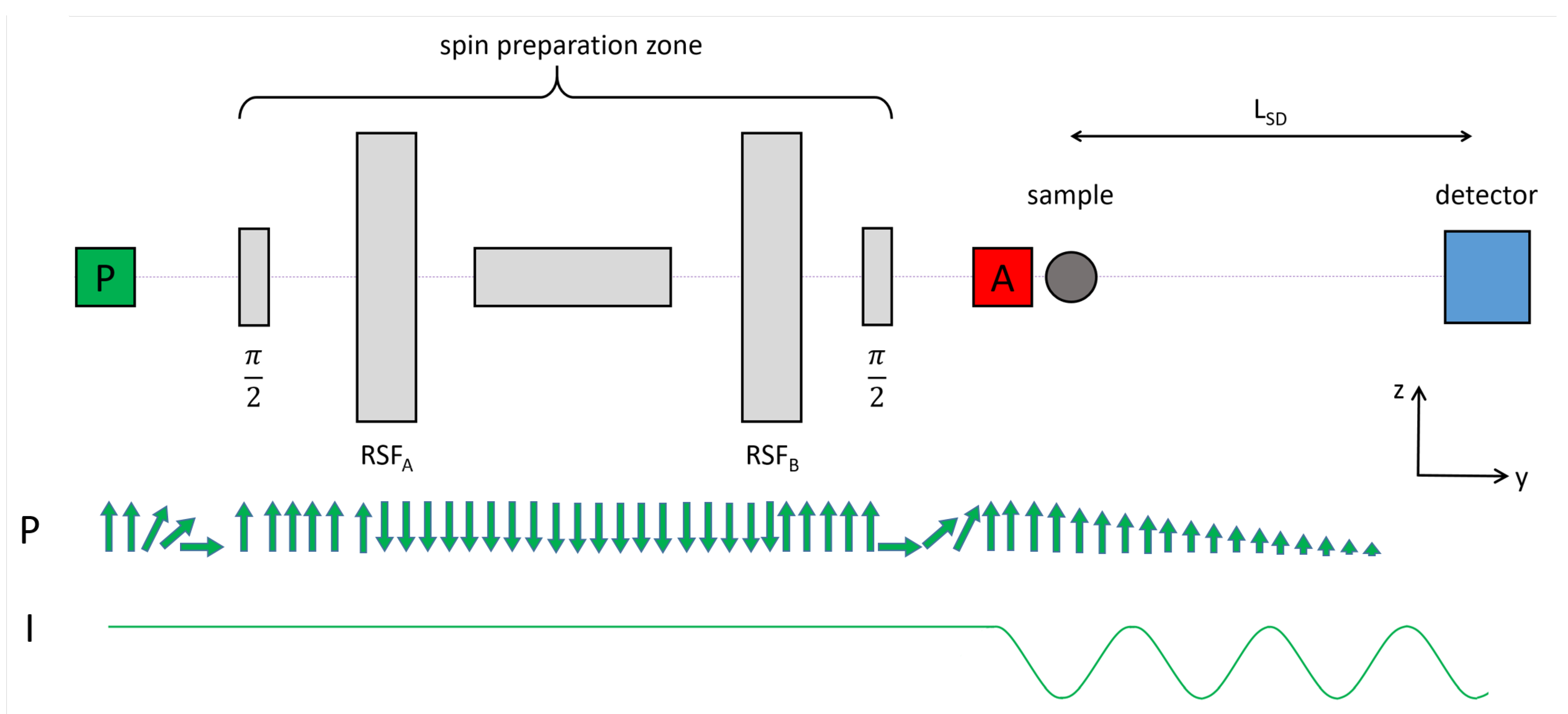
2.3. Transmission Bender Device for MIEZE Applications
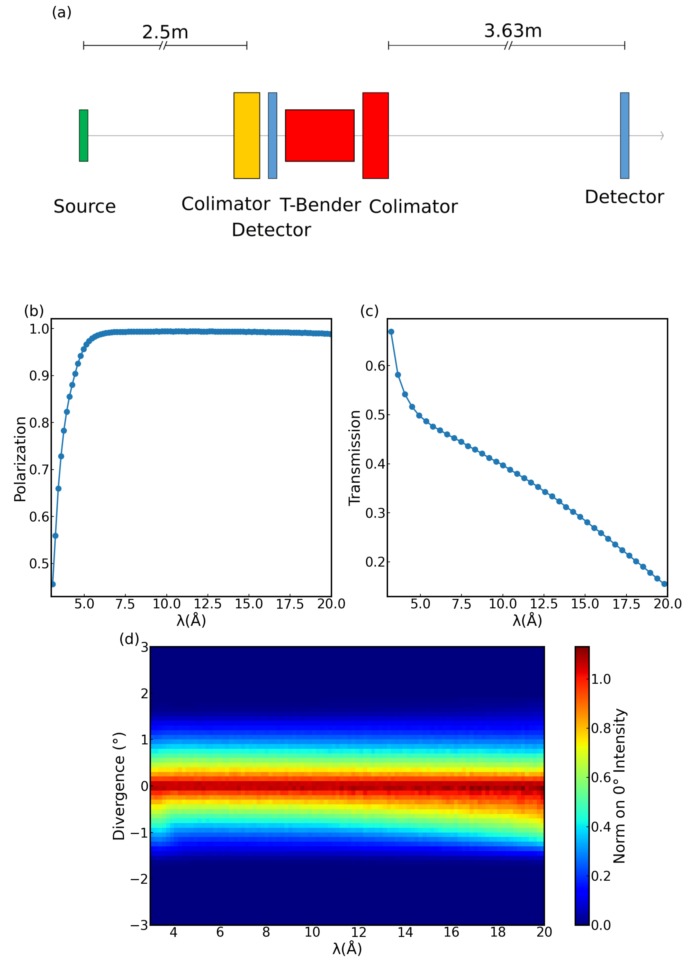
The analysis of present-day state of the art devices leads to the conclusion that, for MIEZE at RESEDA, a transmission bender will be the best choice as a polarization analyzer. It offers high polarization without changing the beam direction, beam divergence, or beam homogeneity. Moreover, diffuse scattering is strongly reduced in comparison to reflection geometry. While a transmission bender may not offer quite as high a Q–resolution as a 3 He transmission filter, it is much easier to operate during long measurement times. In addition, the transmission bender is more compact and can be integrated into the experimental setup more easily. Furthermore, the sensitivity of the 3 He filter to external magnetic fields makes it difficult to use in a longitudinal MIEZE setup, in which large magnetic fields at the sample position may be applied.
Taking these aspects into account, we decided to use a m = 5 polarizing bender with an additional 120 collimator to absorb the reflected beam. A 120 collimator will permit a maximum divergence of 2 , absorbing the up-spin neutrons, which are reflected at an angle of 3.9 . Additionally, the collimator will transmit the full divergence given by the m = 1.2 neutron guide upstream of the analyzer for wavelengths up to 15 Å, thus not sacrificing neutron flux for experiments that require a relaxed spatial resolution. For experiments in SANS geometry, tighter collimation can be utilized. The collimator is coated with Gd, which creates high energy gamma radiation upon neutron absorption. Therefore, it is advisable to install gamma shielding around the device. A photograph of the device is shown in Figure 2, and the specifications of the analyzer and collimator, produced by SwissNeutronics [16], can be found in Table 1.

Simulations

We performed ray-tracing Monte Carlo Simulations using McStas 2.7.1 [17] to confirm the suitability of the transmission bender. The setup we used to perform the simulations is shown in Figure 3a. A source creating a wavelength band from 3 Å < λ < 20 Å, followed by a spin randomizing component and a horizontal collimator 2.5 m behind it were used to define a neutron beam similar to the beam at RESEDA. The bender and collimator components, comprising the polarization analyzer were placed 0.8 m after the first collimator. The bender component consisted of 100 modified gravity guide components, progressively tilted to simulate the bent structure. The transmission, polarization, and divergence monitors, all with a cross-section of 0.2 m × 0.2 m, were placed 3.63 m behind the analyzer. The sizes and distances were chosen to match RESEDA’s geometry; however, we selected a broader wavelength band than typically used at RESEDA to evaluate the performance over a wider range of wavelengths.
For this configuration, the wavelength dependent polarization and transmission of the device (c.f. Figure 3b,c), as well as the accepted divergence (Figure 3d), were determined. Here, the polarization lay significantly above 90% for a wavelength range from 4.5 to 20 Å which was in accordance with the requirements at RESEDA. The transmission of the bender was highest for short wavelengths and decreased towards longer wavelengths, since the absorption increased with an increase in the wavelength. For the supermirrors, the transmission was proportional to e n σ a λ d λ 0 , where λ is the neutron wavelength, σ a is the absorption cross-section, d is the supermirror thickness, and λ 0 = 1.798 Å [18]. The normalized divergence stayed constant as a function of wavelength.

3. Experimental Tests
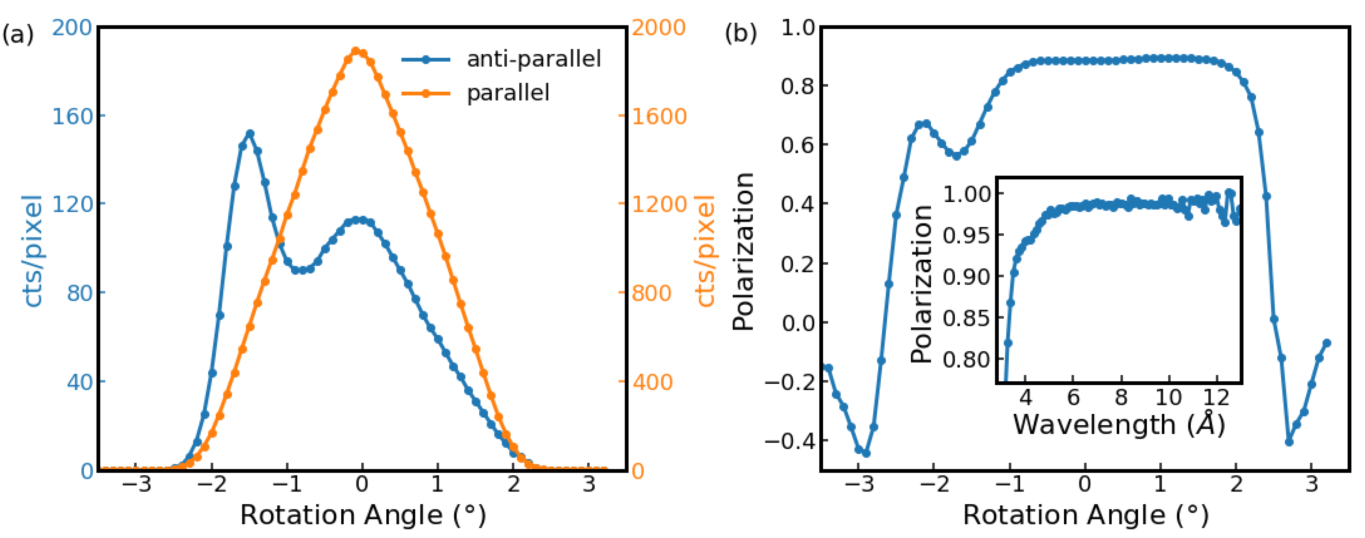
3.1. Commissioning

Commissioning was performed at the RESEDA beamline at the MLZ. For this purpose, the resonant spin flippers were switched off, reducing the setup to the velocity selector, polarizer, guide field, analyzer, and detector. The π /2–flipper in front of the analyzer was used as a π –flipper to switch the polarization of the incident beam. However, the flipping ratios were limited, as there is no guide field compensation for this flipper, leading to a reduced polarization. The transmission bender itself was mounted on a rotation stage to permit rocking scans.
Rocking scans of the transmission bender were performed from +4 to −4 in 0.1 steps, for wavelengths in a direct beam configuration, both with the π –flipper switched on and off. Figure 4a shows the rocking scan with the polarization of the incident neutrons parallel (orange) and antiparallel (blue) to the analyzing direction. The polarization parallel to the analyzing direction showed a peak in the transmission, the shape of which was given by the triangular transmission profile of the collimator. The peak intensities in the antiparallel direction were one order of magnitude lower than in the parallel direction. The peak at 0 corresponded to the spin leakage neutrons with undesired spin direction, while the second peak was due to the reflected beam. Figure 4b shows the polarization calculated from the rocking scans. This was calculated using P = I + I I + + I , where I + / I are the neutron intensities parallel and antiparallel to the polarization direction. The inset of Figure 4b shows the fully corrected (Fredrikze method [19]) polarization of the bender as measured directly at OFFSPEC. It can be seen that the polarization was above 98% for a large wavelength range. As mentioned above, the reduced maximum polarization of 93%, seen in Figure 4b, originated in the limited flipping ration of the π –flipper, which was not optimized. During a standard MIEZE experiment, the polarization is a product of the polarization of the double V cavity, two static π /2–flippers, two resonant π –flippers, and two adiabatic turns giving a maximum polarization of approximately 94% (for a wavelength of 6 Å).
Figure 4. Rocking scans of the transmission bender–collimator combination measured at λ = 6 Å in MIEZE configuration at RESEDA. (a) Polarization of the incident neutrons parallel (orange) and antiparallel (blue) to the analyzing direction. (b) Polarization calculated from the data shown in panel (a). The inset of (b) shows the fully corrected (Fredrikze method [19]) polarization of the bender as a function of the wavelength as measured at OFFSPEC.
Qubs 06 00026 g004
Apart from the polarization, the shape and divergence of the neutron beam are essential parameters for MIEZE measurements, especially for measurements in a SANS configuration. Therefore, it is crucial to guarantee a clean beam. The detector image depicted in Figure 5a shows a smearing of the direct beam in the horizontal direction, with an increased intensity to the left, which is the direction in which the spin-up neutrons are reflected. To remedy this, we inserted an additional 20 horizontal and vertical collimator downstream of the analyzer. As can be seen in Figure 5b, this led to a much better defined direct beam.

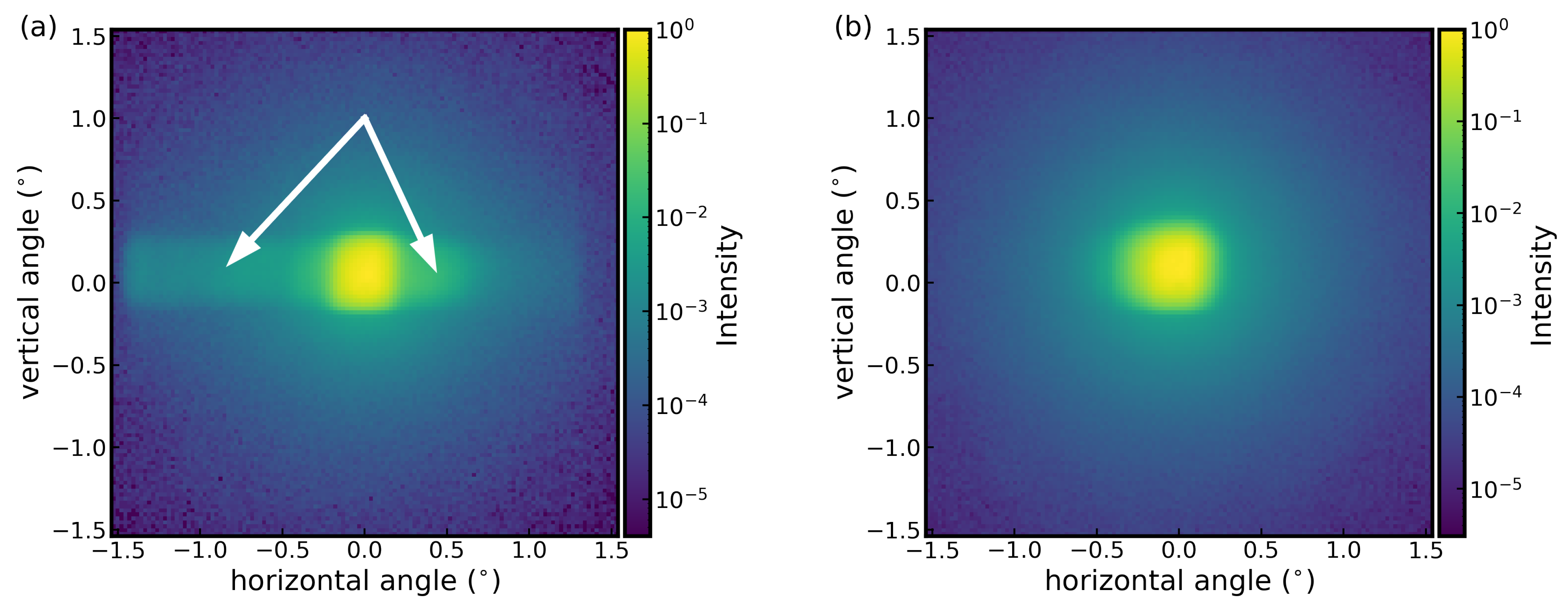
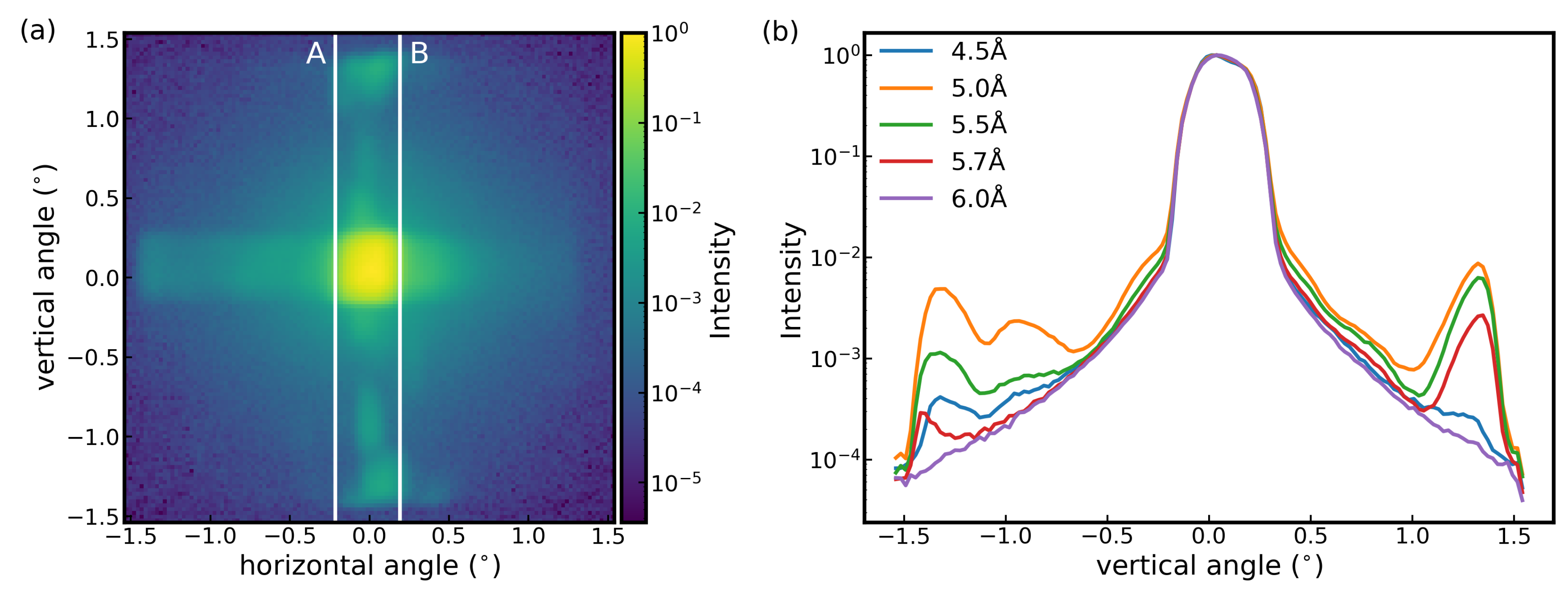
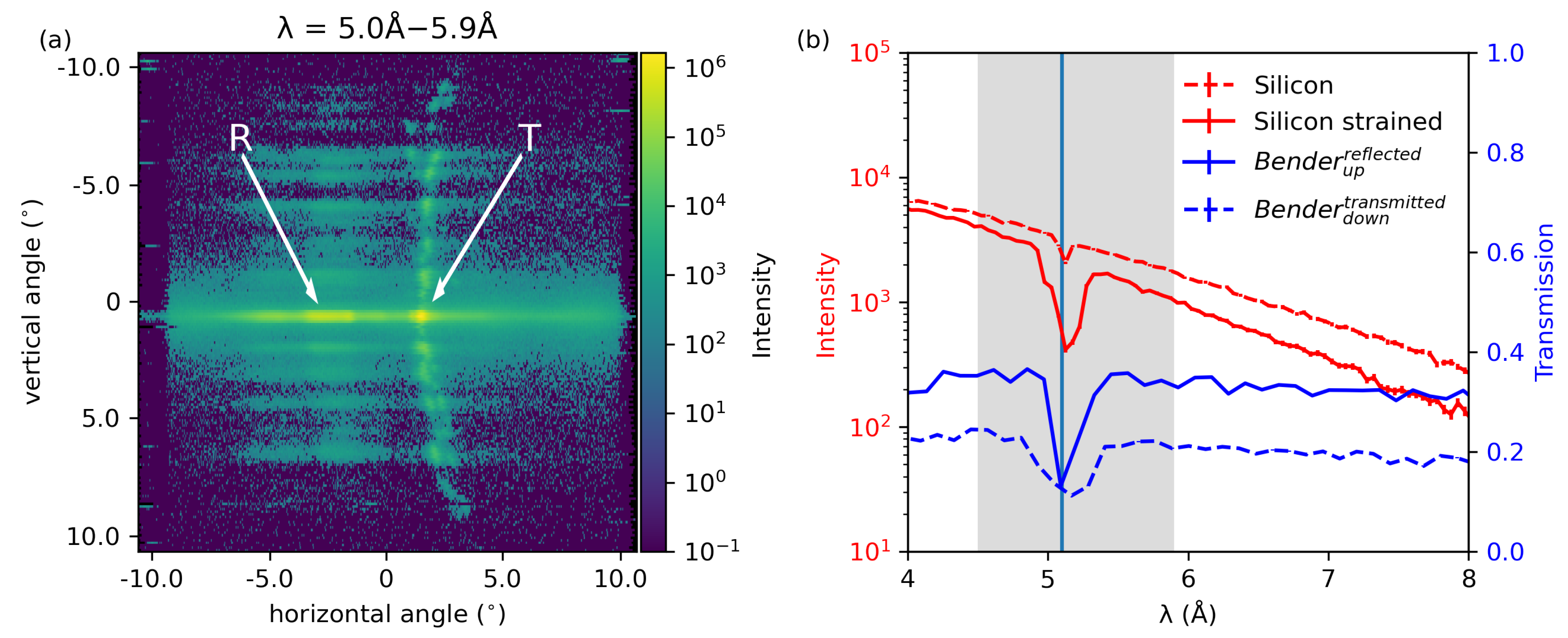
3.2. Spurious Scattering

3.2.1. Experiment

During the commissioning of the transmission bender, some spurious scattering was detected. This scattering was investigated more closely at RESEDA as well as ZOOM and OFFSPEC at the ISIS neutron and muon source. At RESEDA, detector images were recorded for different wavelengths to investigate the wavelength dependent behavior of the transmission bender. A typical detector image is shown in Figure 5. For wavelengths between 4.5 Å and 5.7 Å spurious scattering existed in the vertical plane (see Figure 6a). Figure 6b shows the sum over the area between the vertical white lines in Figure 6a for different wavelengths. The spurious scattering was strongest at 5 Å and decreased towards shorter and longer wavelengths. The spurious peaks maintained their positions for all wavelengths. As the typical wavelengths used at RESEDA are 4.5 Å, 6 Å 8 Å or 10 Å this spurious scattering does not affect the performance of the instrument.
For the measurements at ZOOM, the collimator was removed from the device, and the transmission bender was measured using an unpolarized white beam. An incident wavelength range from 0.5 to 17.5 Å was used, with a sample to detector distance of 4.0 m and a detector diameter of 1.5 m. In this configuration, it was possible to view both the directly transmitted beam and the beam which had undergone at least one reflection. The centers of these two beams were separated by around 19 cm on the detector, corresponding to an angular deviation of 2.7 . This deflection was wavelength independent to within the experimental error. Starting at around 5.0 Å up to 5.9 Å, additional scattering was observed across the whole detector. These features were centered on the transmitted beam and showed a slight curvature away from the reflected beam (see Figure 7a).
To investigate this effect further, data were recorded at OFFSPEC for wavelengths from 1.0 to 14.0 Å using a stack of 20 unpolished single crystal silicon wafers. The wafers were 200 μm thick and 6 cm long and aligned (within a few degrees) with the [110] direction along the neutron beam. Clamps were fixed in three places to hold the wafers together and to apply strain. The transmission of the wafers was measured before and after the clamps were tightened to track the presence of strain. The results of the two transmission measurements together with the transmission of the bender, measured under the same conditions at OFFSPEC, are shown in Figure 7b. In the same wavelength range where the features from the analyzer reported above were observed, a large dip in the strained silicon transmission was present. This suggests that the feature originated in a straining of the silicon in the bender, rather than the supermirror layers. The small dip in the unstrained silicon wafer most likely stemed from small initial strains in the silicon that occurred when installing the clamps.

3.2.2. Discussion

The measurements (Figure 6a and Figure 7a) show that the spurious scattering appeared as localized peaks, resulting from coherent scattering. Additionally, the high intensity of the peaks suggest that the origin was elastic scattering. Measurements with full polarization analysis at OFFSPEC (not shown here) further showed that the scattering was limited to the non-spin-flip channel.
We considered whether the spurious scattering could come from reflections off any of the devices located upstream of the bender in the neutron beam. This was excluded after confirming the scattering was present at RESEDA, ZOOM, and OFFSPEC three completely different setups at different neutron sources. To prove that the scattering did not originate from scattering off the aluminum housing of the transmission bender, we performed experiments with a narrowly collimated beam, where the scattering persisted.
Since the scattering occured in a vertical scattering plane, Zig-Zag and Garland scattering within the Si wafers can be excluded as well [20].
Considering that the scattering occurred at a rather narrow wavelength range, a possible cause for the spurious scattering could be double Bragg scattering within the single wafers or Umweg/Renninger Anregungen, where forbidden peaks can appear in perfect crystals [21,22]. Indeed, similar dips in the transmission of bent Si-based solid-state devices have previously been reported in a similar wavelength range (5.06 Å, [13], 5.10 Å, [23]) and have been attributed to the (111) Bragg reflection.

4. Conclusions

We compared the performance of different polarization analyzers for application in longitudinal MIEZE. We concluded that a transmission bender was the best option for this application, based on the results from the commissioning and characterization experiments, where we found that the bender yielded a high polarization p ≤ 98% and a homogeneous beam. The commissioning experiments uncovered spurious scattering that we analyzed further with measurements at the ZOOM and OFFSPEC instruments at the ISIS neutron and muon source. After excluding all other possible causes for the spurious scattering, we concluded that the spurious scattering originates from double Bragg scattering in the bent silicon wafers of the transmission bender. This does not limit its application at the RESEDA, as the affected wavelengths are rarely used. Furthermore, the issue can easily be resolved by replacing the 120’ collimator with one that offers a collimation of 60’ or tighter.

Author Contributions

Conceptualization, C.F. and O.S.; methodology, C.F.; validation, O.S., P.L. and P.B.; formal analysis, C.F.; investigation, C.F., O.S., J.F.K.C. and J.K.J.; resources, P.B.; writing—original draft preparation, J.K.J.; writing—review and editing, J.K.J., C.F., J.F.K.C., C.P. and P.B.; visualization, J.K.J., C.F. and L.M.V.; supervision, C.F. and J.K.J.; funding acquisition, C.P. and C.F. All authors have read and agreed to the published version of the manuscript.

Funding

This reasearch was funded through the BMBF projects ‘Longitudinale Resonante Neutronen Spin–Echo Spektroskopie mit Extremer Energie–Auflösung’ (Förderkennzeichen 05K16W06) and ‘Resonante Longitudinale MIASANS Spin–Echo Spektroskopie an RESEDA’ (Förderkennzeichen 05K19W05).

Data Availability Statement

The data shown here have been published in a figshare repository: DOI: https://doi.org/10.6084/m9.figshare.19919155.v1 (accessed on 26 July 2022).

Acknowledgments

Useful discussions with Christian Schanzer and Michael Schneider from SwissNeutronics AG about the realization of the bender are gratefully acknowledged.

Conflicts of Interest

The authors declare no conflict of interest.

Abbreviations

The following abbreviations are used in this manuscript:
MIEZEModulation of IntEnsity with Zero Effort
rfradio frequency
SANSSmall angle neutron scattering
SEOPspin exchange optical pumping
MEOPmetastability–exchange optical pumping

References

  1. Honecker, D.; Bersweiler, M.; Erokhin, S.; Berkov, D.; Chesnel, K.; Venero, D.A.; Qdemat, A.; Disch, S.; Jochum, J.K.; Michels, A.; et al. Using small-angle scattering to guide functional magnetic nanoparticle design. Nanoscale Adv. 2022, 4, 1026–1059. [Google Scholar] [CrossRef]
  2. Franz, C.; Soltwedel, O.; Fuchs, C.; Säubert, S.; Haslbeck, F.; Wendl, A.; Jochum, J.K.; Böni, P.; Pfleiderer, C. The longitudinal neutron resonant spin echo spectrometer RESEDA. Nucl. Instrum. Methods Phys. Res. Sect. A Accel. Spectrom. Detect. Assoc. Equip. 2019, 939, 22–29. [Google Scholar] [CrossRef]
  3. Jochum, J.K.; Hecht, A.; Soltwedl, O.; Fuchs, C.; Frank, J.; Faulhaber, E.; Leiner, J.F.K.C.; Pfleiderer, C.; Franz, C. Oscillatory magnetic fields for neutron resonance spin-echo spectroscopy. Meas. Sci. Technol. 2020, 32, 045902. [Google Scholar] [CrossRef]
  4. Jochum, J.K.; Wendl, A.; Keller, T.; Franz, C. Neutron MIEZE spectroscopy with focal length tuning. Meas. Sci. Technol. 2019, 31, 035902. [Google Scholar] [CrossRef]
  5. Cussen, L.D.; Goossens, D.J.; Hicks, T.J. 3He neutron polarising filters—Theoretical comparison with supermirrors and Heusler alloy polarisers. Nucl. Instrum. Methods Phys. Res. Sect. A Accel. Spectrom. Detect. Assoc. Equip. 2000, 440, 409–420. [Google Scholar] [CrossRef]
  6. Xu, J.; Atterving, M.; Skoulatos, M.; Ostermann, A.; Georgii, R.; Keller, T.; Böni, P. Design of a neutron polarizing bender for a cold triple-axis spectrometer. Nucl. Instrum. Methods Phys. Res. Sect. Accel. Spectrom. Detect. Assoc. Equip. 2022, 1031, 166526. [Google Scholar] [CrossRef]
  7. Kreuz, M.; Nesvizhevsky, V.; Petoukhov, A.; Soldner, T. The crossed geometry of two super mirror polarisers—A new method for neutron beam polarisation and polarisation analysis. Nucl. Instrum. Methods Phys. Res. Sect. Accel. Spectrom. Detect. Assoc. Equip. 2005, 547, 583–591. [Google Scholar] [CrossRef]
  8. Gentile, T.R.; Nacher, P.J.; Saam, B.; Walker, T.G. Optically polarized 3He. Rev. Mod. Phys. 2017, 89, 045004. [Google Scholar] [CrossRef] [PubMed] [Green Version]
  9. Chen, W.C.; Gentile, T.R.; Ye, Q.; Walker, T.G.; Babcock, E. On the limits of spin-exchange optical pumping of 3He. J. Appl. Phys. 2014, 116, 014903. [Google Scholar] [CrossRef]
  10. Kindervater, J.; Martin, N.; Häußler, W.; Krautloher, M.; Fuchs, C.; Mühlbauer, S.; Lim, J.A.; Blackburn, E.; Böni, P.; Pfleiderer, C. Neutron Spin Echo Spectroscopy under 17 T Magnetic Field at RESEDA. EPJ Web Conf. 2015, 83, 03008. [Google Scholar] [CrossRef] [Green Version]
  11. Syromyatnikov, V.G.; Pusenkov, V.M. New compact neutron supermirror transmission polarizer. J. Phys. Conf. Ser. 2017, 862, 012028. [Google Scholar] [CrossRef] [Green Version]
  12. Krist, T.; Rucker, F.; Brandl, G.; Georgii, R. High performance, large cross-section S-bender for neutron polarization. Nucl. Instrum. Methods Phys. Res. Sect. Accel. Spectrom. Detect. Assoc. Equip. 2013, 698, 94–97. [Google Scholar] [CrossRef] [Green Version]
  13. Stunault, A.; Andersen, K.H.; Roux, S.; Bigault, T.; Ben-Saidane, K.; Rønnow, H.M. New solid state polarizing bender for cold neutrons. Phys. B Condens. Matter 2006, 385–386, 1152–1154. [Google Scholar] [CrossRef]
  14. Petukhov, A.K.; Nesvizhevsky, V.V.; Bigault, T.; Courtois, P.; Jullien, D.; Soldner, T. A project of advanced solid-state neutron polarizer for PF1B instrument at Institut Laue-Langevin. Rev. Sci. Instrum. 2019, 90, 085112. [Google Scholar] [CrossRef] [PubMed]
  15. Petukhov, A.; Nesvizhevsky, V.; Bigault, T.; Courtois, P.; Jullien, D.; Soldner, T. A concept of advanced broad-band solid-state supermirror polarizers for cold neutrons. Nucl. Instrum. Methods Phys. Res. Sect. A Accel. Spectrom. Detect. Assoc. Equip. 2016, 838, 33–38. [Google Scholar] [CrossRef] [Green Version]
  16. SwissNeutronics. Available online: https://www.swissneutronics.ch/products/neutron-supermirrors/ (accessed on 26 July 2022).
  17. Willendrup, P.K.; Lefmann, K. McStas (i): Introduction, use, and basic principles for ray-tracing simulations. J. Neutron Res. 2020, 22, 1–16. [Google Scholar] [CrossRef] [Green Version]
  18. Sears, V.F. Neutron scattering lengths and cross sections. Neutron News 1992, 3, 26–37. [Google Scholar] [CrossRef]
  19. Fredrikze, H.; van de Kruijs, R. Calibration of a polarized neutron reflectometer. Phys. B Condens. Matter 2001, 297, 143–147. [Google Scholar] [CrossRef]
  20. Lieutenant, K.; Cussen, L.D. Beam transport in double elliptic neutron guides. J. Neutron Res. 2015, 18, 127–134. [Google Scholar] [CrossRef]
  21. Renninger, M. “Umweganregung”, eine bisher unbeachtete Wechselwirkungserscheinung bei Raumgitterinterferenzen. Z. FüR Phys. 1937, 106, 141–176. [Google Scholar] [CrossRef]
  22. Barker, J.G.; Mildner, D.F.R. Survey of background scattering from materials found in small-angle neutron scattering. J. Appl. Crystallogr. 2015, 48, 1055–1071. [Google Scholar] [CrossRef] [PubMed] [Green Version]
  23. Shah, V.R.; Washington, A.L.; Stonaha, P.; Ashkar, R.; Kaiser, H.; Krist, T.; Pynn, R. Optimization of a solid state polarizing bender for cold neutrons. Nucl. Instrum. Methods Phys. Res. Sect. Accel. Spectrom. Detect. Assoc. Equip. 2014, 768, 157–163. [Google Scholar] [CrossRef]
Figure 2. Photograph of the transmission bender used at RESEDA. The magnetic cage, a symbol indicating the curvature of the supermirror, analyzer, and collimator are indicated. The magnetic cage, analyzer, and collimator are sandwiched and held in position by long screws to ensure the stability of the setup. The magnetic cage and the collimator can be removed and/or replaced by a different device.
Qubs 06 00026 g002
Figure 3. (a) Schematic depiction of the McStas setup used for the simulations. (b) Wavelength-dependent polarization of the transmission bender. (c) Wavelength-dependent transmission of the bender, with collimator. Around 10 Å, the polarizer provides about 40 polarized neutrons, if 100 unpolarized neutrons enter the polarizer. (d) Wavelength dependent divergence of the beam, normalized to the intensity of the neutrons with a divergence of 0 .
Qubs 06 00026 g003
Figure 5. Comparison of the detector image at a wavelength of 6 Å. Panel (a) shows the image without an additional collimator where some spurious scattering due to the specular reflected spin-up neutrons appears; panel (b) shows the image with an additional 20 horizontal and vertical collimation, giving a much cleaner beam profile.
Qubs 06 00026 g005
Figure 6. Spurious scattering as caused by the transmission bender device. (a) Detector image with spurious scattering in the vertical plane located within the boundaries, marked A, B. (b) Vertical cuts across the detector image in (a) integrated between A and B. The direct beam corresponds to the intense peak at the detector center. From 4.5 Å to 5.9 Å, additional peaks occur at an angle of ±1.57 close to the top and bottom edges of the detector.
Qubs 06 00026 g006
Figure 7. (a) Spurious scattering of the transmission bender as seen by the ZOOM spectrometer. The reflected and transmitted beam are indicated by R and T, respectively. (b) Spurious scattering from the transmission bender device (blue) and the strained silicon wafers (red), measured at OFFSPEC. The gray shaded area indicates the wavelength range for which the spurious scattering was observed at RESEDA.
Qubs 06 00026 g007
Table 1. Summary of the technical specifications of the transmission bender and the lammelar collimator.
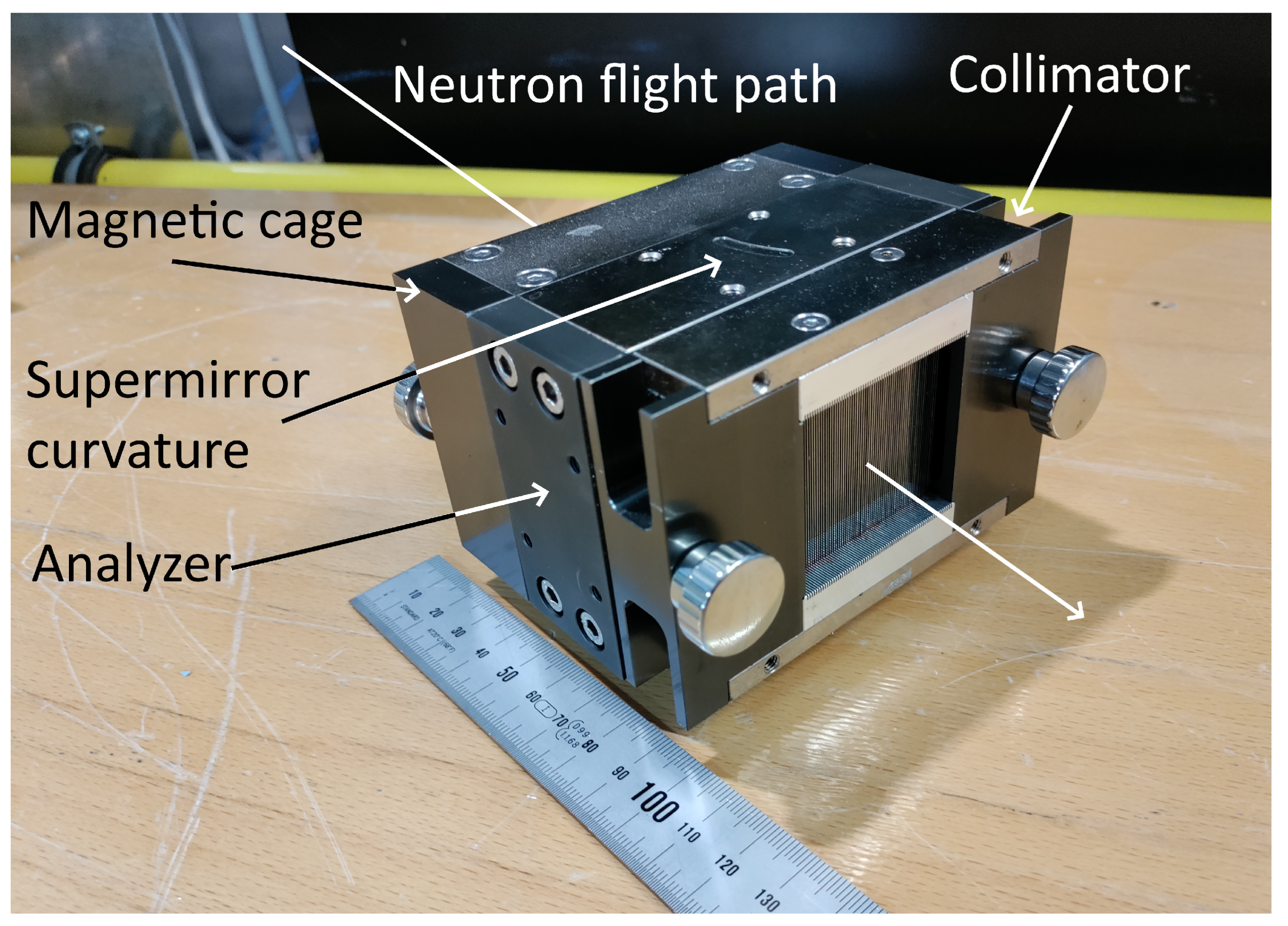
Polarizing Bender with m = 5
Designsolid state
transmission bender
coatingFe/Si m = 5
wafer thickness0.15 mm
radius of curvaturer = 0.56 m
length30 mm
critical wavelength λ c  = 3.24 Å
magnetic fieldB = 45 mT
Solid State Collimator
horizontal collimation120
materialSi
absorbing coatingGd
wafer thickness0.3 mm
length10 mm
Publisher’s Note: MDPI stays neutral with regard to jurisdictional claims in published maps and institutional affiliations.

