1. Introduction
Constructions made of corrugated metal structures (CMS) are promising types of transport structures, both on the railway and the highway, as is reflected in the works of scientists [
1,
2]. The main disadvantage of these structures with increased cross-sections is their low operational reliability due to operational and technical factors [
3,
4]. In [
5,
6], the calculation of the stress-strain state of corrugated metal structures is published depending on the amount of compaction of the soil backfill of the structures. In [
7], a risk assessment model for the construction of small bridges from corrugated metal structures on highways is presented. In [
8], the stress-strain state of a fragment of metal corrugated structures was calculated under the action of climatic temperature effects. The literature [
9] presents a multilayer model for estimating radial, angular, and longitudinal stresses in reinforced concrete pipes reinforced with metal corrugated structures. In [
10,
11], the load-bearing capacity of corrugated metal transport structures was evaluated during their operation on the railway track. As a result, it is noted that to increase the load-bearing capacity of the structures, it is necessary to perform additional reinforcement on structures with large cross-sections. In [
12,
13], it was proven that the bearing capacity is significantly affected by the soil backfill’s compaction degree. Therefore, in the construction of structures made of corrugated metal, it is necessary to ensure the standard degree of compaction of the backfill of 97%.
These include the specifics of functioning the construction with CMS, which are determined by the interaction of a metal coating with a soil backfill; the necessary shape and certain dimension assurance under the condition of limited height of the soil backfill above the structure; and the quality of soil backfill compaction during the construction [
14,
15]. Poor compaction of the soil backfill can lead to uneven subsidence of the embankment over CMS, deformations in the reinforcement of the embankment slope, and, most importantly, residual deformations of the vertical and horizontal cross-sections of corrugated metal structures [
16,
17]. The loss of the structure’s shape has a negative impact on the performance of railways and highways, which include such construction (the appearance of potholes on the carriageway or irregularities on the track) and the durability of the structure’s operation (the appearance of deflections and residual deformations) [
18,
19].
At present, one of the universal methods of increasing the bearing capacity of CMS is the use of transversal stiffeners in the form of additional corrugation (double corrugation). Transversal stiffeners can be used for all forms of cross-sections of corrugated metal structures [
20,
21].
Rigid ribs are most widely used for box structures with large cross sections in which the bending stiffness in the vault of the structure is not provided. Box structures with CMS are used in transport constructions with a height of the soil backfill ranging from 450 mm to 1500 mm that bear different types of loads. The width of such structures varies from 3.170 m to 12.315 m, and the vertical size from 1.180 m to 3.555 m [
17].
The purpose of a stiffening rib is to reduce the vertical deformation of the construction with CMS during soil backfill compaction and increase load capacity during its operation. They are made of corrugated metal sheets, which correspond to the cross-sections of the corrugation of the main construction. Stiffening ribs can also be made of suitable profiled metal products. Depending on the geometrical parameters of the construction and the load class, the stiffeners can be located around the perimeter of the construction or only on its parts. The location of the ribs on the longitudinal section of the construction is also different—they can be continuous or spaced at certain intervals.
In cases of additional reinforcement of the construction, the internal space between the stiffener and the corrugated metal structure can be filled with concrete [
21].
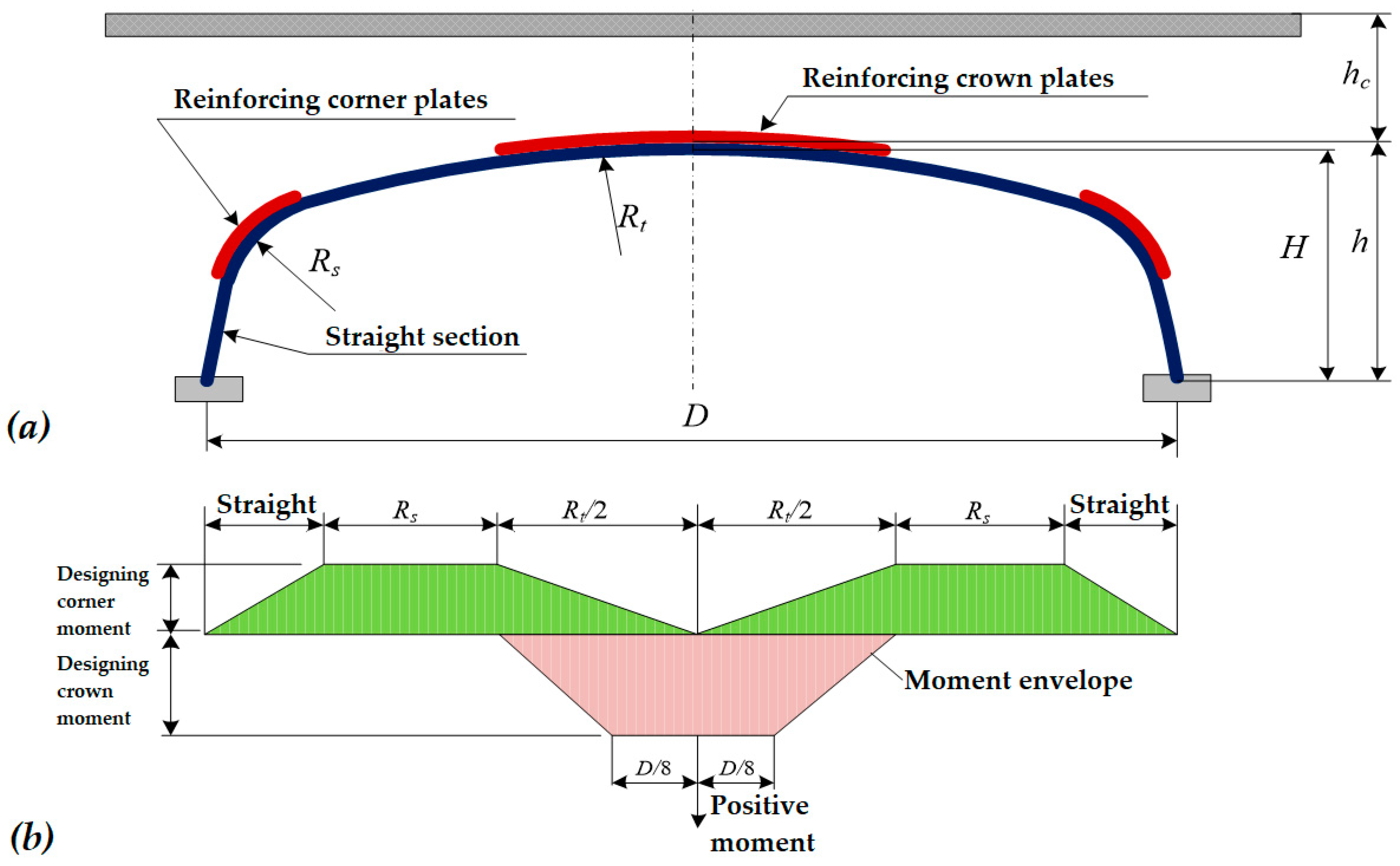
The use of double corrugation (
Figure 1) in the most dangerous sections of transport structures made of metal corrugated structures will increase their bearing capacity. An example of double corrugation of structures is shown in
Figure 1.
It should be noted that the reinforcement of metal corrugated structures by the double corrugation method is relevant for heavy loads arising from the action of railway transport. However, no studies have been found on the effectiveness of such reinforcement of structures operated on railroad tracks. This work is devoted to this issue.
2. Literature Review
In work [
20], it is noted that for economic expediency, the rigidity ribs are established in the most loaded areas of the construction, as shown in
Figure 1.
The construction’s load-bearing capacity should be assessed in places where the stresses are the largest due to bending. The dimensions of the stiffeners are calculated depending on the maximum bending moments’ distribution caused by the action of constant loads from the soil backfill and temporary loads from moving vehicles.
The design bending moment (
Figure 2) is a combined bending moment, which consists of the sum of 2/3 of the bending moment that occurs in the vault of the structure under constant loads of soil backfill compaction and 1/3 of the bending moment caused by the transport load.
In the case of the intermittent arrangement of stiffeners, the calculation of internal force factors begins not with the reinforcing stiffener but with the main structure. Furthermore, if additional reinforcement is required, the required number of stiffeners is added until the section’s resistance to bending is high enough, compared to the minimum required resistance of the section to bending.
After reckoning the number and length of stiffeners, the cross-section of the reinforced node is checked in the same way as without stiffeners, but with the recompute of the equivalent stiffness to bending EI using the geometric parameters of the node connection.
The issue of the interaction of two metal corrugated coatings during the reinforcement of transport constructions with CMS is covered in the works of Bakht and Newhook (2004) and Machelski (2013) [
20,
22,
23].
In the work [
24], numerical and experimental studies of the stress-strain state of box construction with a CMS span of 3.55 m and a rise height of 1.62 m were performed. As a result, it was found that the finite element method has limited applicability in the case of stress determination in construction under the action of moving vehicles [
25].
In work [
26], it is noted that the constructions with CMS are flexible structures, so, at the construction stage, they are usually very “sensitive” to any deviations from the technological standards of their building, which may be the cause of premature decommissioning.
Experimental tests of box corrugated constructions reinforced with transverse stiffeners have shown that the load resistance of constructions is doubled at the level of the vault in comparison with non-reinforced constructions [
18].
In works [
27,
28,
29], it is proposed to install longitudinally reinforced concrete stiffeners symmetrically on both sides of the CMS for reinforcement of metal structures.
In work [
30], the technological schemes for the reinforcement of corrugated structures with the outer transverse stiffeners of the External Rib System (ERS) are presented.
Therefore, the current work aims to develop a method for assessing the load-bearing capacity of corrugated metal structures reinforced with stiffeners and their stress-strain state under the action of loads from the rolling stock of railways.
3. Analytical Method for Assessing the Stress-Strain State of Transport Facilities with CMS Reinforced with Stiffeners
Let us consider two elastic corrugated cylindrical coatings A and B of equal length, attributed to the cylindrical coordinate system
r,
φ,
z (0 ≤
φ < 2π). The cross-section of this structure in the direction of the
z coordinate is shown in
Figure 3.
Internal
S1 and external
S2 surfaces of coating A are described correspondingly by the equations:
and internal
S3 and external
S4 surfaces of coating B are described by the equations:
along the lines
there is a mechanical contact of considered coatings, which is believed ideal.
Coating A is under the action of forces Pr (φ, z), Pz (φ, z) applied to the outer surface S2. The inner surface S1 of coating A and the outer surface S4 of coating B, except for lines (5), are free from loads. The inner surface S3 of coating B and the side surfaces z = ±l of both coatings are also free from loads.
To determine the stress state of the coating and stiffening ribs, equations and relations of the theory of elasticity (6)–(8) are used. The equations of equilibrium for the elementary volume of the considered bodies have the form:
where
σij (
i,
j =
r,
φ,
z)—components of the stress tensor.
The components of the deformation tensor ε
ij (
i,
j =
r,
φ,
z) and the displacement vector
ui (
i =
r,
φ,
z) are related by the ratio:
The stresses
σij and deformations ε
ij are related by Hooke’s law ratio, which has the form:
Here: θ = εrr + εφφ + εzz; —shear Kirchhof’s modulus; ν—Poisson’s ratio.
In this case, the set S is a combination of surfaces S1, S3, and S4, from which lines (5) are subtracted.
According to the conditions of ideal mechanical contact between coatings A and B, the values
at
equal to the values of these magnitudes at
Guide cosines
nr,
nz, which correspond to the surfaces S
1, S
2, are determined by the formulas:
The guide cosines correspond to surface
S3:
and the following values correspond to surface
S4:
where
Given that CMS reinforced with a transverse stiffening rib has different physical and mechanical characteristics than the main construction, in the next section, the method of calculating the axial moment of inertia and cross-sectional area of the reinforced structural node of the construction is considered.
4. Initial Data for Calculation
According to the above method of evaluating the stress-strain state of transport constructions with CMS reinforced with stiffening ribs, it is possible to estimate their stress-strain state. As a basis, the project of an underpass made of CMS is taken, which is intended for railway transport passing, where the highway of the first category passes in the middle. The horizontal diameter of the construction is 9.23 m, and the vertical one is 8.12 m (
Figure 4). The length of the corrugated metal structures is 12.56 m.
The metal sheets of the underpass are made of corrugated structures with a wavelength and height of corrugation of 380 × 140 mm and a thickness of 6 mm. The backfill height above the vault of the CMS underpass is 2.57 m.
The physical and mechanical characteristics of a corrugated metal structure (381 × 140 × 6 mm) and a stiffening rib are given in
Table 1.
Physical and mechanical characteristics of soil backfill compaction in the characteristic areas of a transport construction with CMS are given in
Table 2.
The values of bending stiffness
EIII and normal (axial) stiffness
EAII, which are given in
Table 2, are found based on calculations of the axial moment of inertia
III and the cross-sectional area
AII, taking into account the transverse stiffening rib. The method for calculating the axial moment of inertia is given in the previous section of the article.
Static loading from the own weight of a soil backfill and also temporary loading from locomotive 2 × M62 are accepted as loading. The method of calculating the equivalent forces acting on the sleepers of the railway track at the place of CMS operation is given in
Section 5.
5. Method of Calculating Equivalent Loads from the Action of Mobile Transport Units
The distribution of equivalent forces on sleepers along the track was obtained from track calculations for strength [
31], with the elasticity modulus of the subrail base equal to 73.6 MPa, locomotive speeds of 40, 80, 100, and 120 km/h, and the design state of the railway track. The initial data, which are taken for calculating equivalent forces from the action of mobile transport units, are given in
Table 3.
According to work [
31], in the calculated cross-section of the rail, i.e., in the section where the loads are determined, the maximum probable dynamic wheel load
Pcal =
, and the influence of adjacent and further wheels is taken as an average dynamic pressure
. Given that the maximum dynamic pressure of the design wheel does not coincide with the maximum pressure of adjacent wheels (
Figure 5), the action of two adjacent wheels located on both sides of the design wheel is taken into account in practical calculations, as further wheels have little effect on the load [
31].
The impact on the rail line of all other wheels of the train is taken into account with the influence line loading of transverse forces
Q (from the action of a single wheel load
P = 1) by the system of wheels’ loads
and equivalent loads
determination using the function
η3, which specifies the degree of influence on the calculated cross-section of every other wheel of the train (see
Figure 4).
The calculation of equivalent dynamic loads is performed according to work [
31] by Equation (14):
where:
—maximum dynamic load from the wheel on the rail;
—average value of the dynamic vertical load of a wheel on the rail;
ηi—ordinates of deflection lines influence of a rail in the cross sections of the track, located under the wheel loads from the axes of the carriage adjacent to the design axis.
The function
ηi depends on the value of
kxi where
xi corresponds to distances from the calculated cross section to each wheel, which are taken into account (Equation (15)):
Neighboring wheels can have both positive and negative effects (due to changes in the sign of the function
η along the length of the beam), i.e., they can reload or unload the calculated cross-section [
31]. The forces of rail pressure on the calculated and adjacent sleepers are determined in Equations (16)–(18):
where:
ls—the distance between the axes of the sleepers;
Qp1,
Qc2,
Qc3—respectively, the forces of rail pressure on the design and adjacent sleepers.
When calculating pressure forces on the sleepers
Qp1,
Qc2,
Qc3, the ordinates
ηi of the influence lines of cross-section forces are situated depending on the distances to the sleepers under consideration (for which the pressure
Q is determined) before taking into account the values of wheels (calculated or adjacent). Thus, the ordinates of influence lines
η2,3 take into account the influence of adjacent wheels on the calculated sleeper and correspond to the distances from the axis of the calculated sleeper to the adjacent wheels (left and right), i.e., for distances
X2 and
X3 (
Figure 6).
The ordinates ηp2 and ηp3 take into account loads influenced by the design wheel on the adjacent sleepers and are determined for the distance of the design load location from the considered adjacent and the design sleepers (left or right of it), i.e., for the distance ls = const, there is ηp2 = ηp3.
The ordinates of influence lines ηc2 and ηc3 take into account the influence of the adjacent axes of the carriage on the load of the sleepers adjacent to the calculated one, i.e., correspond to the location distances respectively: for ηc2—distances X2 − ls and X3 + ls; for ηc3—distances X3 − ls and X2 + ls.
By superimposing normal stresses in the soil backfill above the surface of CMS, the total impact of each sleeper in the form of a rectangular load with coordinates relative to the axis of the construction with CMS is taken into account. The calculated scheme of load location from sleepers on a crushed stone ballast layer is given in
Figure 7. The
Y axis corresponds to the track’s axis, and the construction’s axis with CMS corresponds to the
X axis.
Further, to calculate the vertical pressure from a rectangular load corresponding to one sleeper according to the Boussinesq ratio [
32,
33], the compressive stresses for angular points are determined by Equation (19):
where:
p—the intensity of the uniformly distributed load;
l,
b—respectively, the length and width of the loading area.
The value
r is calculated by Equation (20):
Similarly, the stress
σz0 under the center of the loaded rectangle is determined. According to work [
14], the actual load from the rolling stock is converted by the formulas of stress distribution in the Boussinesq half-space into an equivalent linear load, which gives the same vertical stress at the upper level of CMS. Vertical stresses
at the depth
z of an elastic body (vertically under the load), caused by linear load
p in half-space, are determined by Equation (21) [
32,
33]:
For point load, this ratio has the form (Equation (22) [
32,
33]:
where:
s—length of the slope, the distance between the load point and the calculation point;
P—value of the point load from moving vehicles.
After determining stresses by Equations (21) and (22) the equivalent linear load on the top of the CMS is determined by Equation (23):
The equivalent load determined by Equation (23) corresponds to the largest vertical load that falls on the top of CMS from the action of vehicles [
32,
33].
As a result of performing multivariate calculations, the values of equivalent forces for each sleeper are obtained. The results of calculations of forces from locomotive 2 × M62 locomotives are shown in
Figure 8.
As shown in
Figure 8, when the modulus of elasticity of the subrail base is 73.6 MPa, the maximum value of the equivalent forces is 141.4 kN.
Further, the vertical forces of pressure acting on CMS are obtained according to calculated values of equivalent forces. The results of this calculation at locomotive 2 × M62 locomotive speeds of 40 and 120 km/h are shown in
Figure 9.
The value of the vertical pressure on the top of the CMS underpass at locomotive 2 × M62 speed of 40 km/h is 99.42 kPa; at 80 km/h–101.54 kPa; at 100 km/h–102.63 kPa; and at a speed of 120 km/h, 103.77 kPa.
Based on the obtained values of vertical pressure forces, constructive decisions’ operational reliability was assessed to increase the bearing capacity of transport facilities with CMS. The calculation of the stress-strain state of the proposed structural solutions for increasing the load-bearing capacity of constructions with CMS was performed by the finite element modeling method in the licensed software Femap NX Nastran, following the recommendations given in the work [
14].
6. Estimation of Bearing Capacity of a Corrugated Metal Structure Reinforced with Stiffening Ribs
6.1. Calculation of the Axial Moment of Inertia of the Reinforced Structure
To be able to determine the axial moment of inertia of the cross-section of the reinforced node of the structure, the following method of calculation is given: It is assumed that CMS, with transverse dimensions of corrugation of 381 × 140 × 7 mm, is reinforced with a stiffening rib of the same geometric cross-section as the main corrugated structure. For ease of calculation, the basic design is denoted by index “b” and the overhead stiffening rib by index “n” (
Figure 10).
The surface area of a stiffening rib concerning the main metal profile is determined by Equation (24):
The distance between the geometric centers of two cross-sectional elements of the structure is determined by Equation (25):
where:
f is the height of a corrugated metal profile;
t is the arithmetic mean thickness of the main structure and a stiffening rib.
The total moment of inertia of a complex cross-section (in the case of an ideal connection), is calculated by Steiner’s formula:
where
ed =
eg = 0.5
e.
Furthermore, the axial stiffness of the joint can be found, which is equal to EIx.
The finite element model of a corrugated metal structure reinforced with double corrugation consists of 413,946 nodes and 410,800 finite elements.
6.2. Research Results
The finite element model involves specifying the dimensions of the soil backfill and boundary conditions on its surfaces, as well as creating a contact layer at the interface between the soil and the metal shell. The dimensions of the ground backfill exceed the transverse dimensions of the metal structure by approximately 1.5 DTR. To do this, movable joints were set at the edges of the soil backfill at the nodal points of the finite elements, with angular and some linear displacements prohibited.
Regarding the boundary conditions on the soil-metal shell surface, the contact layer was modeled by elastic elements with stiffness characteristics, which are usually used for three-dimensional problems with a smooth, flat pipe surface. This model allows the ground to slip on the surface of the shell.
Parabolic elements with intermediate nodes on the sides were used in the finite element modeling of the reinforced MGK. On the one hand, such elements better model the geometry of the curved surfaces of parts, and on the other hand, they reduce the number of finite elements and, at the same time, increase the order of approximation of the functions of deformations and stresses.
The metal pipe is modeled with flat finite elements of the 2-D type Plate, and the space of the soil in the bosoms of the corrugation is filled with tetrahedra, and then with the distance from the shell, the soil is modeled with hexahedra. The concentration of the finite element grid was performed in places of possible stress concentration and the areas of contact of conjugate bodies (“soil backfill-metal structure”). In particular, near the corrugations, the dimensions of the finite elements were chosen to be smaller, and the rest of the area was divided into elements of larger dimensions.
The finite element model of the metal corrugated structure is shown in
Figure 11.
When modeling the structure, nonlinear ideal-plastic models were used; namely, for the dangers of plastic deformations in the metal of the corrugated structure, the von Mises criterion was set during the calculations.
In this case, the parameters of elasticity (modulus of elasticity, Poisson’s ratio, and density) additionally set the value of the yield strength of the metal structure. Six constants were set for ideal-plastic models of soil such as Moore-Coulomb and Drucker-Prager: two elastic characteristics—the deformation modulus and the Poisson’s ratio; density; and three characteristics of plasticity—the angle of internal friction, the coefficient of adhesion, and the angle of dilatation.
In the nodes of the elements of the lower part of the soil clamp, fixed hinges are set, which makes it impossible for linear movements of the structure in the vertical and horizontal directions, and in the nodes of the elements of the side faces, a ban on horizontal movements is introduced.
To compare the calculation results, the reckoning of the stress-strain state of a CMS with a corrugated profile thickness of 6 mm, but without reinforcing the structure with a stiffening rib, is offered. The simulation results in the form of stress and strain distribution that occur in the metal sheets of the structure are shown in
Figure 12 and
Figure 13.
Figure 12 shows the results of stress calculations (
Figure 12a) and deformations (
Figure 12b) that occur in metal corrugated structures without the double corrugation method.
Figure 13 shows the results of stress calculations (
Figure 13a) and deformations (
Figure 13b), which occur in metal corrugated structures whose arch is reinforced with the double corrugation method.
To evaluate the effectiveness of using the double corrugation method in the reinforcement of transport structures made of metal corrugated structures, the maximum stresses and strains occurring in the arch of the structure without and with the corrugation method are taken as a criterion.
The calculation results of stresses with double corrugation and the use of additional stiffening ribs, which occur in the sheets of the structure, showed that the stresses are less than the allowable value of 235 MPa.
The results of comparing the stress-strain state of a CMS depending on the design of structural reinforcement are given in
Table 4.
From calculations, lower stresses and strains occur in the design variant of increased bearing capacity of a CMS with reinforcing stiffening ribs. The stress that occurs in the sheets of the structure at locomotive 2 × M62 speed equal to 120 km/h is 38.92 MPa, and deformation is 5.56 mm. Without stiffening ribs, the stress is 47.03 MPa, and the deformation is 11.04 mm. Therefore, additional corrugation of corrugated metal structures reduces stresses by up to 20% and deflections by 50%.
The obtained results show that the increase in rolling stock speed does not lead to a significant increase in stresses and strains in CMS when the railway track corresponds to the design state.
However, it should be noted that the installation of additional transverse stiffeners leads to increased economic costs and complexity of work. To establish the most profitable and optimal design solution, conducting a technical and economic evaluation of the design solution in each case of corrugated metal structure strengthening is necessary.


