Article

About the Mechanical Strength of Calcium Phosphate Cement Scaffolds

1
G.E.R.N. Center of Tissue Replacement, Regeneration & Neogenesis, Department of Orthopedics and Trauma Surgery, Medical Center-Albert-Ludwigs-University of Freiburg, Faculty of Medicine, Albert-Ludwigs-University of Freiburg, Hugstetter Straße 55, 79106 Freiburg, Germany
2
Institute for Applied Biomechanics, Offenburg University, Badstraße 24, 77652 Offenburg, Germany
*
Author to whom correspondence should be addressed.
Designs 2023, 7(4), 87; https://doi.org/10.3390/designs7040087
Submission received: 8 May 2023 / Revised: 15 June 2023 / Accepted: 28 June 2023 / Published: 3 July 2023

Abstract

:
For the treatment of bone defects, biodegradable, compressive biomaterials are needed as replacements that degrade as the bone regenerates. The problem with existing materials has either been their insufficient mechanical strength or the excessive differences in their elastic modulus, leading to stress shielding and eventual failure. In this study, the compressive strength of CPC ceramics (with a layer thickness of more than 12 layers) was compared with sintered β-TCP ceramics. It was assumed that as the number of layers increased, the mechanical strength of 3D-printed scaffolds would increase toward the value of sintered ceramics. In addition, the influence of the needle inner diameter on the mechanical strength was investigated. Circular scaffolds with 20, 25, 30, and 45 layers were 3D printed using a 3D bioplotter, solidified in a water-saturated atmosphere for 3 days, and then tested for compressive strength together with a β-TCP sintered ceramic using a Zwick universal testing machine. The 3D-printed scaffolds had a compressive strength of 41.56 ± 7.12 MPa, which was significantly higher than that of the sintered ceramic (24.16 ± 4.44 MPa). The 3D-printed scaffolds with round geometry reached or exceeded the upper limit of the compressive strength of cancellous bone toward substantia compacta. In addition, CPC scaffolds exhibited more bone-like compressibility than the comparable β-TCP sintered ceramic, demonstrating that the mechanical properties of CPC scaffolds are more similar to bone than sintered β-TCP ceramics.

1. Introduction

Europe and the USA are in the midst of demographic change. The consequences of this are becoming more and more apparent every year [1,2]. In the EU, the average age continues to rise. One in five Europeans are already older than 65 [3]. In Germany, one in two are older than 45 and one in five are older than 66 [4]. In the US, the average age is 38.1 and, according to a study by the U.N. [5], the average age forecast is 43.1 years in 2050. As a result, age-related diseases such as those affecting the musculoskeletal system are continuing to increase in prevalence. For example, the implantation of a hip endoprosthesis is already the sixth most common surgical intervention in Germany [6]. With the increase in the prevalence of such surgeries, the demand for clinically approved bone replacement materials will also continue to grow. However, until now, many problems, e.g., with metallic implants, have been caused by the imbalance in the elasticity moduli between bone and the metals used. This thus results in so-called stress shielding (undesirable or too weak bone growth) [7]. Biodegradable biomaterials are a potential alternative whose support function decreases as the healing process progresses due to their eventual complete degradation, which allows the support function of the bone to eventually take over [8]. In the past, biodegradable calcium phosphate ceramics in particular have stood out due to these characteristics [9,10,11], especially because they have a similar composition to bone and can be degraded by the bone cells. However, in order for this degradation to function correctly, it is necessary to have sufficient porosity [12]. Both hydroxyapatite (HA) and beta tricalcium phosphate (β-TCP) are suitable for these applications—HA because it is the same material as in bone, and β-TCP because it is also a calcium phosphate like HA but has better solubility [8]. However, there is still a large difference between CaP ceramics and bone, particularly in the fracture elongation of bones, which can be up to 1–2%, compared to ceramics, which break at best at 0.1% [13]. Moreover, the compressive strength and Young’s modulus are in some cases (for ceramics) up to a factor of 10-foldgreater [14], which again raises the problem of stress shielding. Bone does not consist exclusively of HA, but rather of nano-crystalline HA platelets packed in collagen strands. Additionally, bone adapts to mechanical loads according to Wolff’s law and becomes stronger in stressed areas [15], and no biomaterial has so far been able adapt to the changing forces that bone experiences.
In addition to these issues, ceramics partially shrink during the sintering process, sometimes by even up to 30% [16], which must be taken into account for a precisely fitting shape, e.g., for filling defects in the bone. It is easier to create implants from a larger ceramic block directly on site in the operating room based on the bone defect. It also makes sense to use artificial substitute materials in view of an increasingly aging population, due to the limited availability of natural grafts. Additive manufacturing processes in particular have enormous potential, especially for individual patient care. For example, if bone material is missing after a fracture or after the removal due to infection, this individual lesion can be converted into a digital 3D construct (CAD) using clinical imaging techniques (CT, MRI) [17]. This 3D model of the damaged bone can then be used to produce a bone substitute [18], e.g., by milling it from a sinter ceramic block (HA or β-TCP) or by 3D printing. This bone substitute can then be perfectly adapted to the individual case and can ensure mechanical stability, and can thus take over the function of the damaged bone during the healing period. Additive manufacturing also offers a great opportunity for patient-specific replacement. These replacements can be custom-made from calcium phosphate cement (CPC) using 3D printing [19]. This also has the advantage of being a biodegradable ceramic [19,20], which can be broken down by the body. Ideally, once it has done its job and the bone has healed, it is completely degraded. This eliminates the need for a second surgery to remove the structure, with all of the associated risks. To enable even faster healing and new bone formation, additives such as growth factors and/or antibiotics [21,22,23] can also be incorporated into the cement. Commercially available CPC especially for injection at defect sites in the bone or for 3D printing do not set until they come into contact with water. For this purpose, an oil phase is usually dispersed, which escapes during the imaging reaction and can be absorbed by the body [20]. As with other cements, the setting reaction with water takes time [24]. During this period, the CPC scaffolds cannot be mechanically loaded. Importantly, printed CPC scaffolds could serve as a support and guidance structure during the bone healing process. In addition, the surface of the printed CPC scaffold plays an important role in regeneration [25]. In this work, both systems, namely sintered ceramics and 3D-printed CPC scaffolds, were to be compared with regard to their mechanical properties [22,26] to determine if 3D-printed scaffolds exhibited similar mechanical properties to bone. To achieve this, we first focused on 3D printing more than 12 layers [27,28,29] so that we could produce comparably sized specimens. The working hypotheses were that (1) as the number of layers increased, the mechanical strength of the 3D-printed CPC scaffolds would increase and (2) the internal needle diameter would influence the mechanical strength, which would better mimic the mechanical strength of the bone than what is possible with sintered ceramics.

2. Materials and Methods

2.1. Materials

Conical printer needles with 0.2 (article No.: 561751MA) and 0.25 (article No.: 561751MA) mm inner diameters were purchased from VIEWEG GmbH (Kranzberg, Germany). The CPC paste for printing (20 mL, article No.: 087-020-PL) was purchased from Innotere (Radebeul, Germany). Phosphate buffered saline (PBS) (Thermo Fisher Scientific, Waltham, MA, USA) was purchased from ThermoFisher (article No.: 14190-094).

2.2. β-TCP Ceramics

The β-TCP ceramics used in this work were produced according to our specifications by the Robert Mathys Foundation (RMS) [11,22,23,30]. In this process, 20 g of tricalcium phosphate (Art. No. 102143, Merck, Switzerland) and 80 g of α-tricalcium phosphate (α-TCP; Ca3(PO4)2) were mixed with a 60.0 ± 0.2 g solution of 0.2 M Na2HPO4 and 1% polyacrylic acid (Art. No. 81132, Fluka, Switzerland; Mw = 5.1 kDa). The paste was stirred intensively for 2.5 min and then transferred to a plastic syringe. The plastic syringe was 70 mm long and had a diameter of 23 mm. After 45 min, the paste was covered with 10 mL of PBS (part no. P5368, Sigma, USA), at pH 7.4, and incubated at a temperature of 60 °C for 3 days. The green bodies were then dried at the same temperature. Sintering was performed at 1250 °C for 4 h with a heating and cooling rate of 1 °C/min. The ceramic cylindrically shaped bodies were then cut to a diameter of 7 mm and a length of 25 mm. In a final step, the ceramic scaffolds were washed in an ethanol bath and calcined at 900 °C to burn away all abrasive particles and organic residues [31].

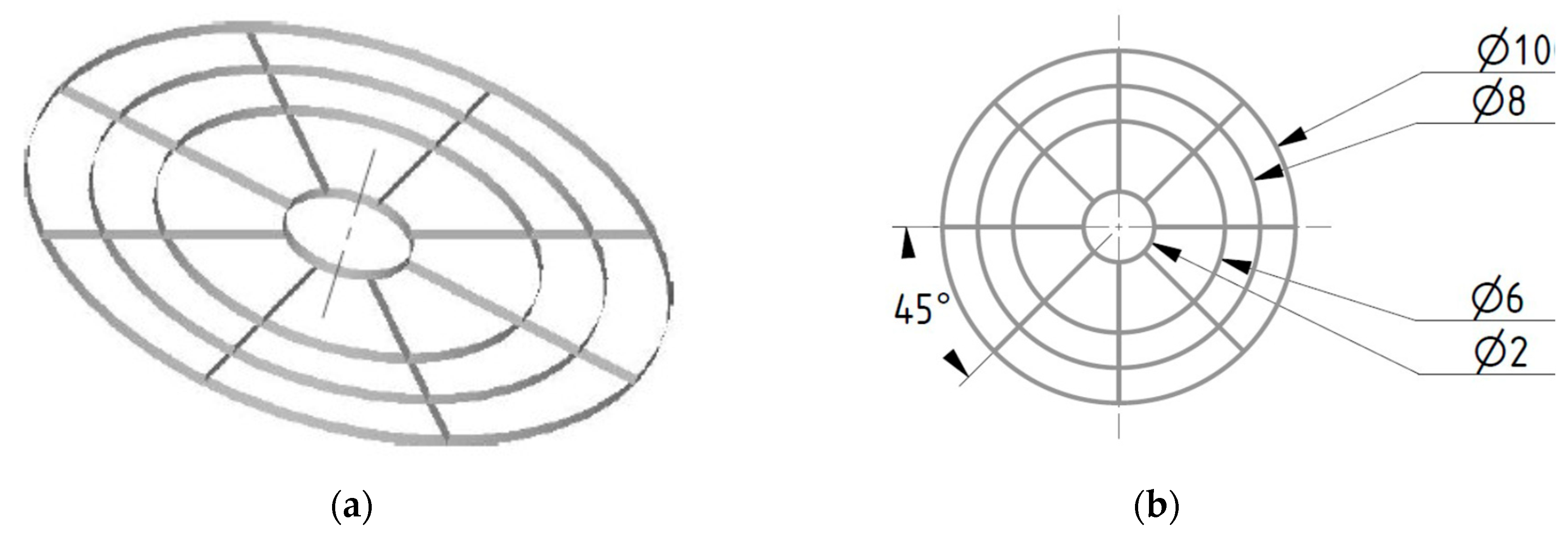
2.3. Three-Dimensional Printing

We used a 3D bioplotter (EnvisionTec, Gladbeck, Germany) with a low-temperature print head and conical needles made from polypropylene with inner diameters of 0.2 and 0.25 mm to print the round geometry that we developed. The CPC paste used was made by Innotere GmbH (Innotere, Radebeul, Germany). It consisted of synthetic calcium and phosphate salts finely dispersed in a biocompatible oil phase of short-chain triglycerides (caprycil/capric triglycerides) together with two further emulsifiers (polyoxyl-35-castor oil/cetyl phosphate). The triglycerides and the polyoxyl-35-castor oil (castor oil) were both based on pure raw vegetable materials [32].

2.3.1. Optimizing Printing Parameters

The parameters were referred to as optimized if the printed strand width was similar in width to the inner needle diameter of the needle used. In the present case, for an inner needle diameter of 0.20 mm, the desired strand width was 0.20 mm. The same then applied for an inner needle diameter of 0.25 mm. This was important so that the structure did not collapse. The geometry therefore needed to remain the same from layer to layer. To achieve this, the printing parameters were varied. The printing parameters were:
  • The pressure (bar);
  • The printing speed (mm/s);
  • The needle offset (mm);
  • The post-flow (s);
  • The pre-flow (s).
The 3D printing parameters determined the way the material was printed. They had a special influence on the width of the printed strands. Thus, the first task was to determine the optimal printing parameters. In a previous work, these printing parameters were determined using the “Parameter Tuning” of the “Visual Machines” software [28]. For this purpose, several lines were printed where pressure and speed were varied. However, it was found that the measured widths depended on the printed shape (e.g., circle) and did not correspond in comparison to the printed line using the “Parameter Tuning” function. That is, the printed shapes also played a role in the actual printed strand width. So, to find the optimal printing parameters for the CAD model (see Figure 1), single-layer samples of the CAD model were printed, varying the printing parameters. The pre-flow was kept at 0.15 s. The scaffolds were printed with conical needles (Vieweg GmbH, Kranzberg, Germany) with a diameter of 0.20 (Art. No.: 501611) and 0.25 mm (Art. No.: 501610).

2.3.2. Printing the Round Geometries with More Than 12 Layers

In previous works [33,34], cube-shaped geometries were printed using patterns from the Visual Machines software (EnvisionTec, Gladbeck, Germany). In one of our previous works [28], round structures with a layer rotation of 1° showed good results regarding mechanical strength, but were limited to 12 layers. In addition, there were printing errors such as delamination of the layers. The CPC paste itself probably caused this problem. This is because the CPC paste is not solid after printing, which means that the printed strands are not stable and are deformed by their own weight. To counteract this, water was sprayed onto the green body after a defined number of printed layers to add strength to the structure. A preliminary test was conducted to determine when the water needed to be sprayed onto the green bodies and how much time was needed after that for the structure to be sufficiently strong for additional layers. Water was sprayed onto the green bodies every 7 layers for the samples printed with a needle with a 0.20 mm inner diameter and every 5 layers for those printed with a needle with an inner diameter of 0.25 mm (see Table 1). The scaffolds were set for 3 days at 37 °C according to Akkineni et al. [35] in an incubator in a water-saturated atmosphere. After this time, half of the printed scaffolds were additionally incubated in phosphate buffered saline (PBS) for 1 week with daily changes of the PBS.

2.4. Characterization of the Scaffolds: 3D-Printed and Sintered

The dimensions of all scaffolds (3D-printed and sintered) were measured with a digital caliper (Burg-Wächter, Wetter-Volmarstein, Germany). The surface roughness (center roughness) was characterized by means of 3D laser scanning microscopy (Keyence VK-X 200; Keyence, Osaka, Japan) at 200x and 400x magnification. For phase composition analysis, XRD (Bruker D8 Advance, Bruker Corp., Billerica, MA, USA) and ESEM (FEI Quanta 250 FEG, FEI, Hilsboro, OR, USA) with an EDX unit (Oxford Instruments, Abingdon, UK) were used. The measuring conditions of ESEM were 20 kV acceleration voltage, 115 Pa pressure and, for EDX, 10 kV, 5 min counting time (lifetime) and area scan. The measuring conditions of Bruker D8 Advance were as follows: Bragg–Brentano geometry, equipped with a Cu anode and secondary graphite monochromator, scintillation counter, 40 kV/40 mA, 1°2 theta/min, step size 0.02°2 theta. The following Rietveld refinement analysis of the XRD data was performed by using profex 4.3 (freeware, www.profex-xrd.org). The porosity of the β-TCP scaffolds was measured via mercury porosimetry Porotec 140/440 (Porotec GmbH, Hofheim, Germany). The overall porosity of the 3D-printed scaffolds was determined using image analysis with Gimp 2.10.34 (open-source image editor, gimp.org). The mechanical strength, compression modulus and maximum failure load of the different scaffolds were determined using a Zwick Z005 universal testing machine (Zwick/Roell, Ulm, Germany). For this purpose, a compression test was performed with a preload of 1 N applied to the scaffolds, and the maximum failure load was determined at a traverse speed of 1 mm/s in a displacement-controlled manner.

2.5. Statistics

All results are expressed as means ± standard deviations. Measured values were analyzed using one-way analysis of variance (ANOVA) with a significance level of p < 0.05. Origin 2022 Professional SR1 (OriginLab, Northampton, MA, USA) was used for all statistical analyses.

3. Results

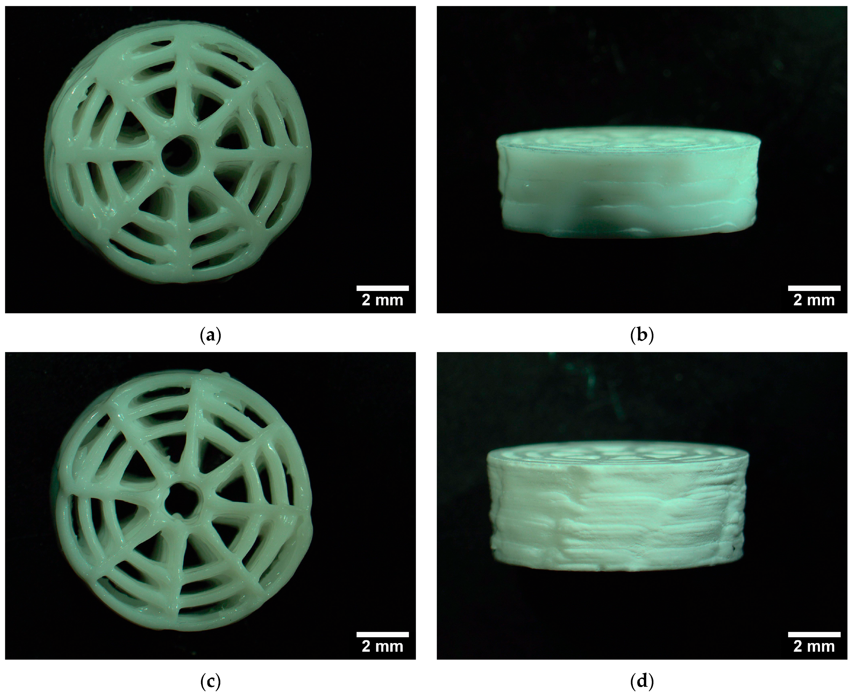
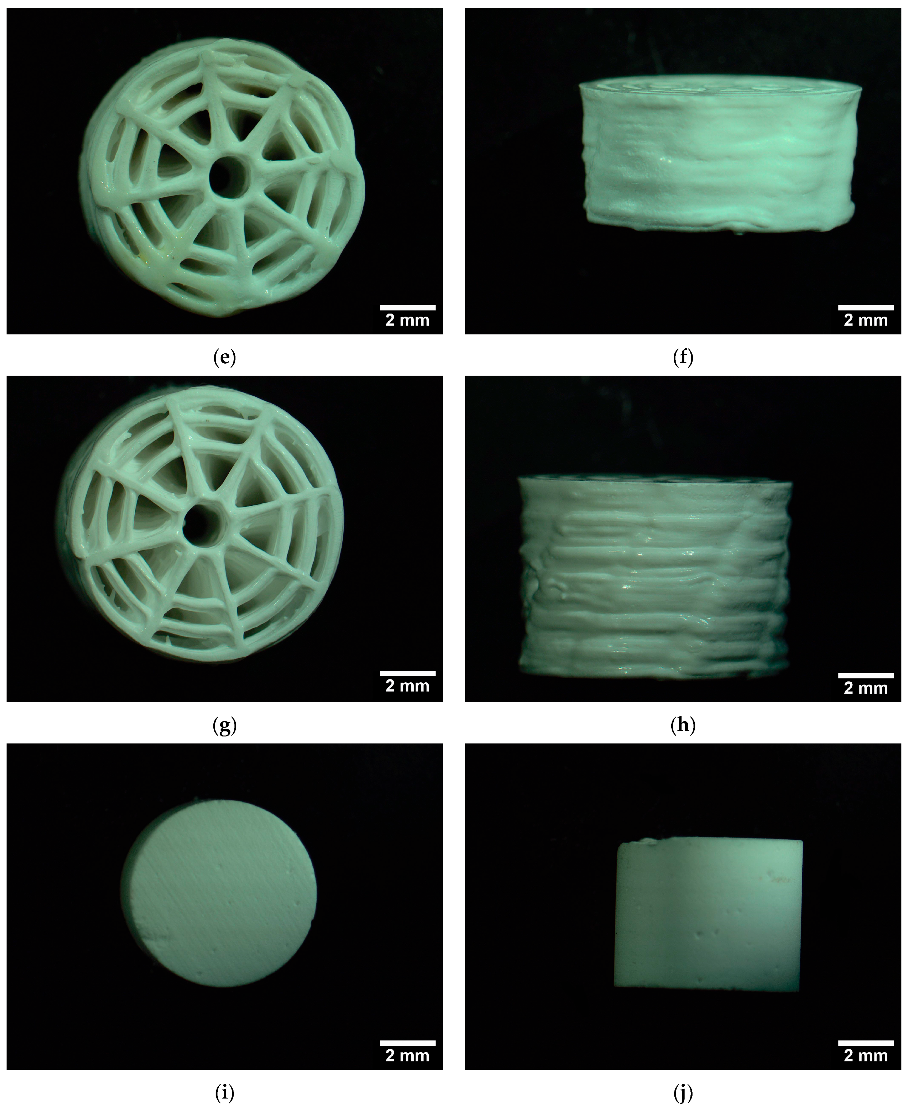
3.1. Characterization of the Scaffolds

3.1.1. Dimensions

The results of the dimensions of the printed or sintered scaffolds, which were measured with the aid of a caliper gauge, are shown in Table 2. The scaffolds printed with 0.20 and 0.25 mm needles had a diameter of 10.5 ± 0.10 mm. The height varies (depending on the number of layers) from 3.4 to 9.5 ± 0.10 mm. No differences in height were observed between samples incubated for one week in PBS and the samples that were not incubated (please see Table 2 and Figure 2).

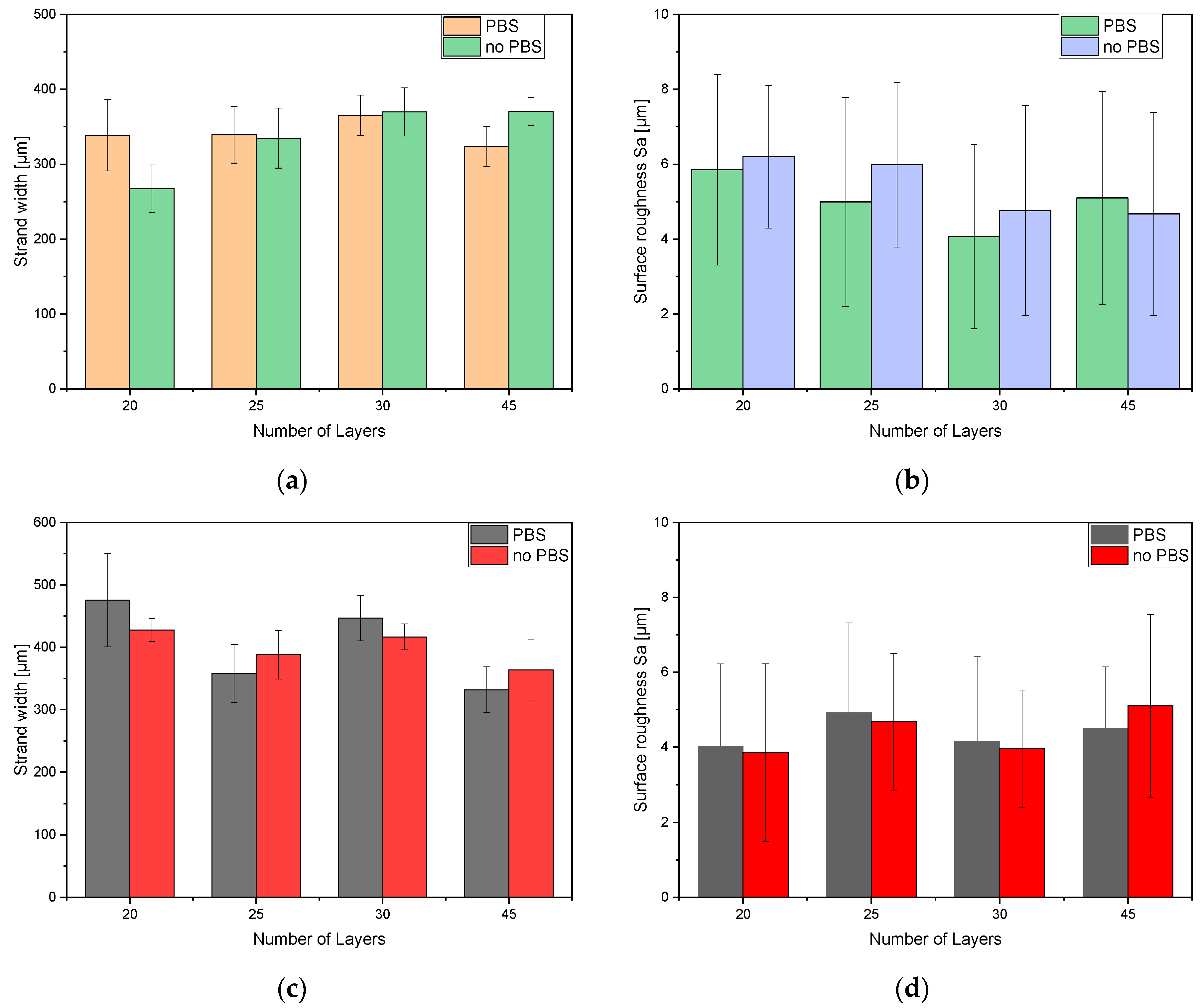
3.1.2. Strand Width and Surface Roughness (Sa)

The strand widths were measured by comparing scaffolds with and without post-consolidation in PBS. For the scaffolds printed with a 0.20 mm needle, the minimum strand width was 267.26 ± 31.83 μm (20 layers) and the maximum was 369.83 ± 32.16 μm (30 layers). There was no significant difference in strand width between the samples with and without PBS post-consolidation. For the scaffolds printed with 0.25 mm needles, the maximum was 475.50 ± 52.98 μm (20 layers) and the minimum was 331.95 ± 26.12 μm (45 layers). Just as for the scaffolds printed with 0.2 mm needles, no significant differences were found between the scaffolds printed with 0.25 mm needles with and without post-consolidation in PBS. In general, however, all strand widths are larger than the inner needle diameters of 0.2 mm and 0.25 mm, respectively (please see Figure 3).
The values of the measured surface roughness Sa for the scaffolds printed with 0.20 mm needles ranged from 4.42 ± 1.79 μm to 7.16 ± 1.76 μm. The samples with incubation in PBS showed a rougher surface. The surface roughness Sa measurements for the scaffolds printed with 0.25 mm needles showed mean values ranging from 4.15 ± 0.97 μm to 6.17 ± 1.55 μm. A comparison is shown in Figure 3.

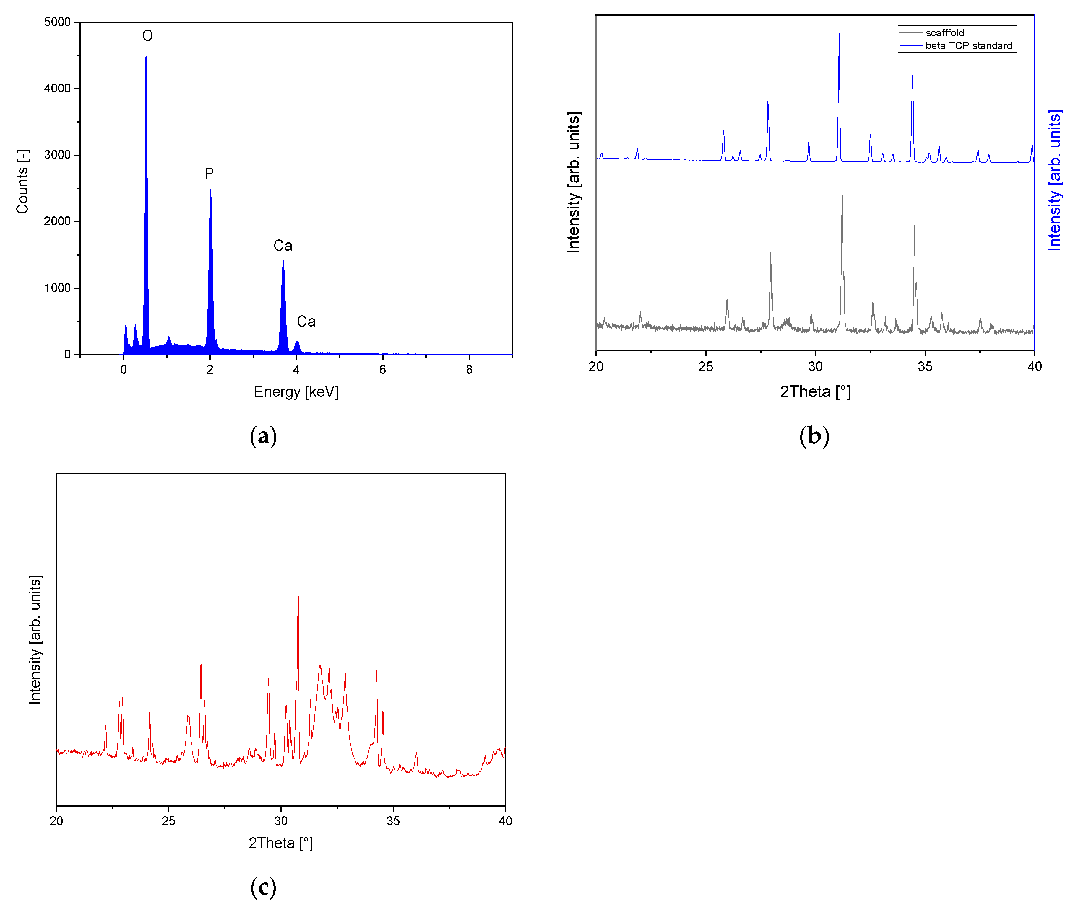
3.1.3. Phase Composition (EDX and XRD)

In the EDX investigation, a calcium phosphate ratio of 1.53 was determined for the sintered ceramic. This means that it is most likely β-TCP [8]. The additional XRD examination (compared to the β-TCP standard, and following Rietveld refinement analysis) confirmed this hypothesis (99.5% β-TCP and traces of CPP). Additional ESEM images of the 3D-printed scaffolds and sinter ceramics are shown in Figure A1. Phase composition analysis of the 3D-printed scaffolds using XRD with subsequent Rietveld refinement analysis revealed a composition of 9% calcium-deficient hydroxyapatite (CDHA), 46% hydroxyapatite (HA), 27% α-TCP and 18% dicalcium phosphate (DCPA). The XRD patterns of the scaffolds used are summarized in Figure 4. The Rietveld refinement analyses can be found in Figure A2 in the Appendix A.

3.1.4. Porosity

Our β-TCP ceramics had pore sizes in the range of 1–5 µm (orange bars in Figure 5a) and were very porous (see also the ESEM images in the Appendix A). The (weighted) pore size distribution was determined with the mercury porosimeters Pascal 140 and 440, as summarized in the following diagram in Figure 5 (purple curve—Pascal 140; red curve—Pascal 440). The average pore diameter was 4.2 ± 0.6 µm. The total porosity was determined with a value of 41.7 ± 2.1%. The total porosity of the 3D-printed scaffolds determined via image analysis was 38.8 ± 2.7%. No significant differences could be observed (see Figure 5b).

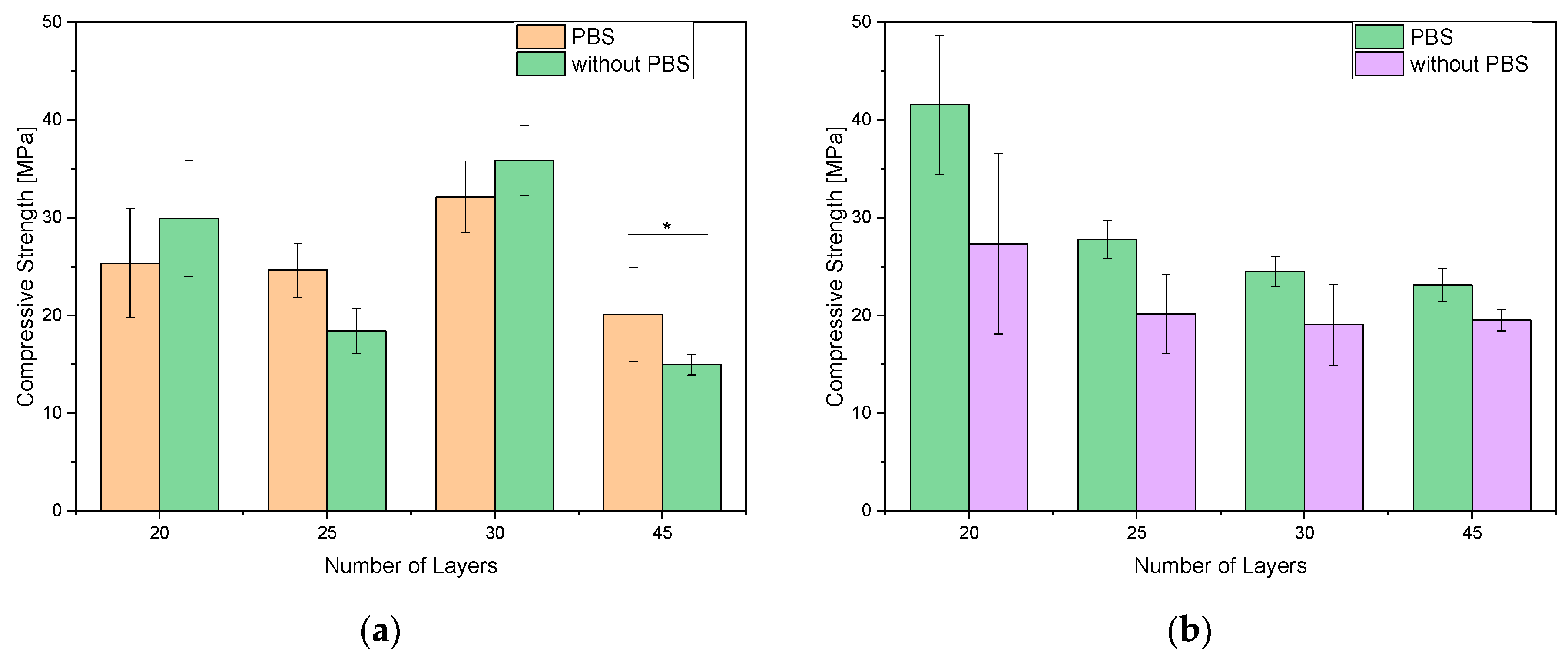
3.1.5. Mechanical Properties

The compressive strength values of the 3D-printed scaffolds ranged from 14.97 ± 1.08 MPa as a minimum to 41.6 ± 7.12 MPa as a maximum. With a few exceptions, there was no difference in the compressive strength of samples with post-incubation or no post-incubation in PBS. There was no significant difference in the compressive strength values of the sintered β-TCP ceramics between native samples or those incubated in PBS. The compressive strength of the sintered β-TCP ceramics was 24.16 ± 4.44 MPa, which was within the compressive strength range of the 3D-printed scaffolds and comparable to the values of the 3D-printed scaffolds with 20 and 25 layers (0.20 mm needle i.d.) with incubation in PBS and the scaffolds with 20, 25 and 30 layers (0.25 mm needle i.d.). Looking at the areas underlying the compressive strength of the 3D-printed scaffolds as well as the β-TCP ceramic, both had similar overall porosities, except for the fact that the pores were more contiguous in the 3D-printed scaffold than in the β-TCP ceramic. Figure 6 shows an overview of the different compressive strengths for the sintered ceramic and 3D-printed scaffolds. Table 3 shows the summary of the compressive moduli for the 3D-printed and sintered scaffolds. There were no significant differences between the samples post-cured in PBS and the samples that were not post-cured. However, a trend can be seen in the samples incubated in PBS where the compression modulus increases as the number of layers increases, while the compression modulus for the sintered ceramics is significantly higher than for the 3D-printed scaffolds.
Figure 7 shows an example of a CPC scaffold after mechanical testing. It can be seen that the upper outer rings up to the base ring have been blown off, whereas the central rings are still standing. This damage pattern is representative for all tested CPC scaffolds.

4. Discussion

4.1. Strand Width and Surface Roughness Sa

The characterization of the samples with respect to the strand widths did not show any significant differences whether post-consolidation in PBS was performed after printing or not. This is due to the fact that water was sprayed every five to seven layers during 3D printing for intermediate consolidation of the green bodies in order to prevent the samples from slumping. In the work of Blankenburg et al. [28], only 12 layers of maximum height could be achieved before printing defects such as delamination occurred. By spraying with water, more than 12 layers could be printed. For time reasons, we limited ourselves to 45 layers, because after spraying with water, we waited 30 s before resuming the printing process. The fact that the strand widths were larger than the inner diameter of the needles is not surprising. This was due to the 3D plotting process, in which an overlay of the strands of 10–20% needs to be achieved to obtain the maximum strength of the construct. Raymond et al. [36] described a similar 3D plotting with 10% overlapping strands. As in Blankenburg et al. [28], there were no significant differences in the surface roughness of the scaffolds regardless of whether the samples were incubated in PBS or not. There were also no significant differences in surface roughness between the two needles with a 200 and 250 µm inner diameter.

4.2. Elemental Analysis EDX and XRD and Microstructure by ESEM

Elemental analysis using EDX (Ca/P ratio 1.53) and XRD (Rietveld refinement with profex 4.3) yielded 99% β-TCP, as observed in similar studies by our group followed by Rietveld refinement analysis. We have already performed similar verifications for the sinter ceramics in the past [22,37,38]. The Rietveld refinement analysis of the 3D-printed scaffolds resulted in a main phase of HA of about 46%, followed by 27% α-TCP, 18% DCPA and 9% CDHA. Fathi et al. [39] also describe the formation of a CDHA phase after their CPC was soaked for a week in water. Our ESEM images showed similar fractured surfaces as described by Fathi et al. [39]. The microstructure of the β-TCP is comparable with that previous published by Mayr et al. [40] or Bohner et al. [11].

4.3. Mechanical Properties

The compressive strength of the 3D-printed scaffolds increased with the number of layers for the scaffolds printed with an inner needle diameter of 0.20 mm to a maximum value of 35.86 ± 3.56 MPa at 30 layers. For the scaffolds printed with an inner needle diameter of 0.25 mm, the compressive strength decreased from 41.56 ± 7.12 MPa to 23.12 ± 1.71 MPa as the number of layers increased. From the preliminary tests and previous work [28], it was found that 3D printing with a larger inner needle diameter also increased the compressive strength. Looking at the results in Figure 6 for the 20-layer scaffold only, this assumption is correct. The compressive strength of the 20-layer scaffolds printed with a needle with an inner diameter of 0.25 mm was 39.1 ± 2.3% higher than that of the scaffolds printed with a needle with an inner diameter of 0.20 mm. Our working hypothesis was that, in addition, with an increasing number of layers, an increase in compressive strength would also be expected. Incubation in PBS led to a doubling of the compressive strength in the previous work [28], so we also incubated in PBS in this work. The increase in compressive strength was only noticeable in the scaffolds printed with a 0.25 mm needle inner diameter, at 27.9 ± 7.9%. Only two of four scaffolds showed an increase in compressive strength when printed with a 0.20 mm inner diameter needle. The reason for the deviation in compressive strength in terms of the number of layers is the formation of micro-cracks due to wetting with water during 3D printing. In addition, the bond between the wetted layers and the subsequent printed layer was not as strong as the bond between the non-wetted layers.
Nevertheless, the 3D-printed scaffolds were more compressive than the microporous β-TCP sintered ceramics, with a compressive strength of 24.16 ± 4.44 MPa. Similar values have already been determined in previous studies [22,30,40]. Miyamoto et al. [41] achieved a compressive strength of 4–10 MPa with their CPC scaffolds. Li et al. [42] also used round geometries, but unfortunately they did not perform mechanical tests. Additionally, Raymond et al. [36] only achieved values of 1–6 MPa with their 3D-printed CPC scaffolds depending on geometry. Similarly, Wu et al. [43] reached a compressive strength of 3.57 ± 0.12 MPa with their 3D-printed calcium silicate scaffolds. However, one must considering that the bone tissues for which the scaffolds are intended as a substitute during healing, namely cancellous and compact bone, have compressive strength values (in the upper range) of 6–45 MPa and 80–150 MPa, respectively [44]. Based on the work of other authors such as Olszta et al. [45], our 3D-printed scaffolds achieved values slightly above those for cancellous bone (2–20 MPa) and in the range between cancellous and compact bone [46].
Looking at compressibility (since we were limited to compression testing due to the scaffold geometry) rather than fracture elongation, the 3D-printed scaffolds were able to compress by 4–5% before total failure occurred (without first breaking out parts erupted from the scaffolds), whereas the β-TCP scaffolds broke after compression by only 0.05–0.1%. This is also reflected in the much lower compressive modulus values in Table 3. Thus, at least in terms of fracture elongation and compressibility, the 3D-printed scaffolds are in the range of bone [13].

4.4. Novelty Character and Limitations of the Present Study

Previous 3D printing experiments were limited to 12 layers [27,28] because otherwise the green body would deform under its own weight, which led to printing errors such as stringing, oozing or layer separation when printing more than 12 layers. Wu et al. [47] only studied CPC scaffolds at a 2 mm height. By spraying during printing after five to seven layers, it was possible to prevent the CPC from collapsing. This shows that future CPC scaffolds can be 3D printed as a bone substitute material of any height using the described technique. The limitation of this technique lies in the time factor. Three-dimensionally printing six scaffolds at the same time takes 1 min per layer and, with the breaks for spraying, this results in a pure printing time of 49 min for spraying after five layers and 48 min for spraying after seven layers. Of course, this problem could be circumvented by using a different CPC. However, slow-setting CPCs have not yet been described for 3D printing in the literature. This would also cause another problem: the printing parameters would vary over time as the setting process begins, and the results would no longer be reproducible.

5. Conclusions

In this work, we wanted to compensate for the disadvantages of sintered β-TCP ceramics, namely the fracture elongation, through 3D printing of comparable (external) geometries. We showed that CPCs’ 3D printing could be improved so that more layers (above 12) can be printed. Thus, by spraying with water, we were able to print significantly more layers than in previous works [28]. This prevented the green body from collapsing under its own weight during 3D printing. The surface roughness was in a similar range and did not differ significantly from the conical printer wires used. While post-curing in PBS did not lead to a significant increase in the compressive strength as in previous works [28], importantly, thanks to the 3D printing geometry, we were able to double the compressive strength compared to sintered ceramics to achieve values similar to compact bone. Since we were limited to a compression test with our scaffolds, we could not measure fracture elongation, but rather the compressibility of the scaffolds. The 3D-printed scaffolds could be compressed by 4–6% to failure, whereas the β-TCP scaffolds failed after being compressed by 0.05–0.1%. Thus, the mechanical properties of 3D-printed CPC scaffolds are more similar to bone than the sintered β-TCP ceramics. This could be useful for the regeneration of bones in the musculoskeletal system where a load-bearing function is required during bone healing.

Author Contributions

Conceptualization, M.S. and J.V.; methodology, M.S.; software, S.Z.; validation, E.B., S.Z. and M.S.; formal analysis, E.B.; investigation, E.B.; resources, H.S.; data curation, S.Z. and M.S.; writing—original draft preparation, E.B. and M.S.; writing—review and editing, M.S.; visualization, S.Z.; supervision, M.S. and J.V.; project administration, M.S. and H.S.; funding acquisition, M.S.: All authors have read and agreed to the published version of the manuscript.

Funding

The article processing charge was funded by the Baden-Württemberg Ministry of Science, Research and Art and the University of Freiburg in the funding program Open Access Publishing.

Data Availability Statement

The data presented in this article are available on request from the corresponding author.

Acknowledgments

The authors would like to thank Melanie Lynn Hart for the spell check and grammar corrections.

Conflicts of Interest

The authors declare no conflict of interest.

Appendix A

Figure A1. ESEM images of the (a,b) 3D-printed scaffolds and (c,d) sinter ceramics.
Designs 07 00087 g0a1aDesigns 07 00087 g0a1b
Figure A2. Rietveld refinement analysis of the XRD pattern of (a) β-TCP ceramics; (b) CPC (after 3d in water saturated atmosphere); pattern recorded using Bruker D8 Advance with a Cu Kα X-ray source.
Designs 07 00087 g0a2aDesigns 07 00087 g0a2b
Figure A3. Maximum failure load for scaffolds 3D printed with a (a) 0.20 mm needle inner diameter, a (b) 0.25 mm needle inner diameter and (c) β-TCP sinter ceramics scaffolds.
Designs 07 00087 g0a3

References

  1. Behrendt, H.; Runggaldier, K. [A problem outline on demographic change in the federal republic of germany]. Notfall + Rettungsmedizin 2009, 12, 45–50. [Google Scholar] [CrossRef]
  2. Peters, E.; Pritzkuleit, R.; Beske, F.; Katalinic, A. Demografischer wandel und krankheitshäufigkeiten. Bundesgesundheitsblatt Gesundheitsforschung Gesundheitsschutz 2010, 53, 417–426. [Google Scholar] [CrossRef] [PubMed]
  3. Eurostat. European Union: Age Structure in the Member States in 2019. Available online: https://de.statista.com/statistik/daten/studie/248981/umfrage/altersstruktur-in-den-eu-laendern/ (accessed on 25 March 2023).
  4. Destatis. Mitten im Demografischen Wandel. Available online: https://www.destatis.de/DE/Themen/Querschnitt/Demografischer-Wandel/demografie-mitten-im-wandel.html (accessed on 2 September 2020).
  5. U.N. World Population Prospects 2022. Available online: population.un.org (accessed on 20 February 2023).
  6. Destatis. Gesundheit—Fallpauschalenbezogene krankenhausstatistik (drg-statistik) operationen und prozeduren der vollstationären patientinnen und patienten in krankenhäusern (4-steller); Statistisches Bundesamt (Destatis): Wiesbaden, Germany, 2020. [Google Scholar]
  7. Engh, C.A., Jr.; Young, A.M.; Engh, C.A., Sr.; Hopper, R.H., Jr. Clinical consequences of stress shielding after porous-coated total hip arthroplasty. Clin. Orthop. Relat. Res. 2003, 417, 157–163. [Google Scholar] [CrossRef] [PubMed]
  8. Epple, M. Biomaterialien und Biomineralisation, eine Einführung für Naturwissenschaftler, Mediziner und Ingenieure; Teubner: Sonnewalde, Germany, 2003. [Google Scholar] [CrossRef]
  9. Jarcho, M. Calcium phosphate ceramics as hard tissue prosthetics. Clin. Orthop. Relat. Res. 1981, 157, 259–278. [Google Scholar] [CrossRef]
  10. Ducheyne, P.; Qiu, Q. Bioactive ceramics: The effect of surface reactivity on bone formation and bone cell function. Biomaterials 1999, 20, 2287–2303. [Google Scholar] [CrossRef]
  11. Bohner, M.; van Lenthe, G.H.; Grünenfelder, S.; Hirsiger, W.; Evison, R.; Müller, R. Synthesis and characterization of porous-tricalcium phosphate blocks. Biomaterials 2005, 26, 6099–6105. [Google Scholar] [CrossRef]
  12. Karageorgiou, V.; Kaplan, D. Porosity of 3d biomaterial scaffolds and osteogenesis. Biomaterials 2005, 26, 5474–5491. [Google Scholar] [CrossRef]
  13. Jacob, H.A.C. Materialverhalten (knochen und implantatwerkstoffe) bei mechanischer beanspruchung. In Orthopädie und Unfallchirurgie: Für Praxis, Klinik und Facharztprüfung; Grifka, J., Kuster, M., Eds.; Springer: Berlin/Heidelberg, Germany, 2011; pp. 29–47. [Google Scholar] [CrossRef]
  14. Akao, M.; Aoki, H.; Kato, K. Mechanical properties of sintered hydroxyapatite for prosthetic applications. J. Mater. Sci. 1981, 16, 809–812. [Google Scholar] [CrossRef]
  15. Pearson, O.M.; Lieberman, D.E. The aging of wolff’s “law”: Ontogeny and responses to mechanical loading in cortical bone. Yearb. Phys. Anthropol. 2004, 125, 63–99. [Google Scholar] [CrossRef]
  16. Tian, J.; Tian, J. Preparation of porous hydroxyapatite. J. Mater. Sci. 2001, 36, 3061–3066. [Google Scholar] [CrossRef]
  17. Figliuzzi, M.; Mangano, F.; Mangano, C. A novel root analogue dental implant using ct scan and cad/cam: Selective laser melting technology. Int. J. Oral Maxillofac. Surg. 2012, 41, 858–862. [Google Scholar] [CrossRef]
  18. Igawa, K.; Mochizuki, M.; Sugimori, O.; Shimizu, K.; Yamazawa, K.; Kawaguchi, H.; Nakamura, K.; Takato, T.; Nishimura, R.; Suzuki, S.; et al. Tailor-made tricalcium phosphate bone implant directly fabricated by a three-dimensional ink-jet printer. J. Artif. Organs 2006, 9, 234–240. [Google Scholar] [CrossRef]
  19. Xu, H.H.K.; Wang, P.; Wang, L.; Bao, C.; Chen, Q.; Weir, M.D.; Chow, L.C.; Zhao, L.; Zhou, X.; Reynolds, M.A. Calcium phosphate cements for bone engineering and their biological properties. Bone Res. 2017, 5, 17056. [Google Scholar] [CrossRef] [Green Version]
  20. Vorndran, E.; Geffers, M.; Ewald, A.; Lemm, M.; Nies, B.; Gbureck, U. Ready-to-use injectable calcium phosphate bone cement paste as drug carrier. Acta Biomater. 2013, 9, 9558–9567. [Google Scholar] [CrossRef]
  21. Ghosh, S.; Wu, V.; Pernal, S.; Uskoković, V. Self-setting calcium phosphate cements with tunable antibiotic release rates for advanced antimicrobial applications. ACS Appl. Mater. Interfaces 2016, 8, 7691–7708. [Google Scholar] [CrossRef] [Green Version]
  22. Seidenstuecker, M.; Ruehe, J.; Suedkamp, N.P.; Serr, A.; Wittmer, A.; Bohner, M.; Bernstein, A.; Mayr, H.O. Composite material consisting of microporous β-tcp ceramic and alginate for delayed release of antibiotics. Acta Biomater. 2017, 433–446. [Google Scholar] [CrossRef]
  23. Kuehling, T.; Schilling, P.; Bernstein, A.; Mayr, H.O.; Serr, A.; Wittmer, A.; Bohner, M.; Seidenstuecker, M. A human bone infection organ model for biomaterial research. Acta Biomater. 2022, 144, 230–241. [Google Scholar] [CrossRef]
  24. Takagi, S.; Chow, L.C.; Hirayama, S.; Sugawara, A. Premixed calcium–phosphate cement pastes. J. Biomed. Mater. Res. Part B Appl. Biomater. 2003, 67B, 689–696. [Google Scholar] [CrossRef] [PubMed]
  25. Lu, J.; Descamps, M.; Dejou, J.; Koubi, G.; Hardouin, P.; Lemaitre, J.; Proust, J.-P. The biodegradation mechanism of calcium phosphate biomaterials in bone. J. Biomed. Mater. Res. 2002, 63, 408–412. [Google Scholar] [CrossRef]
  26. Seidenstuecker, M.; Mrestani, Y.; Neubert, R.H.H.; Bernstein, A.; Mayr, H.O. Release kinetics and antibacterial efficacy of microporous β-tcp coatings. J. Nanomater. 2013, 2013, 8. [Google Scholar] [CrossRef] [Green Version]
  27. Huber, F.; Vollmer, D.; Vinke, J.; Riedel, B.; Zankovic, S.; Schmal, H.; Seidenstuecker, M. Influence of 3d printing parameters on the mechanical stability of pcl scaffolds and the proliferation behavior of bone cells. Materials 2022, 15, 2091. [Google Scholar] [CrossRef] [PubMed]
  28. Blankenburg, J.; Vinke, J.; Riedel, B.; Zankovic, S.; Schmal, H.; Seidenstuecker, M. Alternative geometries for 3d bioprinting of calcium phosphate cement as bone substitute. Biomedicines 2022, 10, 3242. [Google Scholar] [CrossRef] [PubMed]
  29. Egorov, A.; Riedel, B.; Vinke, J.; Schmal, H.; Thomann, R.; Thomann, Y.; Seidenstuecker, M. The mineralization of various 3d-printed pcl composites. J. Funct. Biomater. 2022, 13, 238. [Google Scholar] [CrossRef]
  30. Seidenstuecker, M.; Schmeichel, T.; Ritschl, L.; Vinke, J.; Schilling, P.; Schmal, H.; Bernstein, A. Mechanical properties of the composite material consisting of β-tcp and alginate-di-aldehyde-gelatin hydrogel and its degradation behavior. Materials 2021, 14, 1303. [Google Scholar] [CrossRef]
  31. Stahli, C.; Bohner, M.; Bashoor-Zadeh, M.; Doebelin, N.; Baroud, G. Aqueous impregnation of porous beta-tricalcium phosphate scaffolds. Acta Biomater. 2010, 6, 2760–2772. [Google Scholar] [CrossRef]
  32. Khairoun, I.; Boltong, M.G.; Driessens, F.C.; Planell, J.A. Effect of calcium carbonate on clinical compliance of apatitic calcium phosphate bone cement. J. Biomed. Mater. Res. 1997, 38, 356–360. [Google Scholar] [CrossRef]
  33. Seidenstuecker, M.; Schilling, P.; Ritschl, L.; Lange, S.; Schmal, H.; Bernstein, A.; Esslinger, S. Inverse 3d printing with variations of the strand width of the resulting scaffolds for bone replacement. Materials 2021, 14, 1964. [Google Scholar] [CrossRef]
  34. Muallah, D.; Sembdner, P.; Holtzhausen, S.; Meissner, H.; Hutsky, A.; Ellmann, D.; Assmann, A.; Schulz, M.C.; Lauer, G.; Kroschwald, L.M. Adapting the pore size of individual, 3D-printed cpc scaffolds in maxillofacial surgery. J. Clin. Med. 2021, 10, 2654. [Google Scholar] [CrossRef]
  35. Akkineni, A.R.; Luo, Y.; Schumacher, M.; Nies, B.; Lode, A.; Gelinsky, M. 3d plotting of growth factor loaded calcium phosphate cement scaffolds. Acta Biomater. 2015, 27, 264–274. [Google Scholar] [CrossRef]
  36. Raymond, S.; Maazouz, Y.; Montufar, E.B.; Perez, R.A.; González, B.; Konka, J.; Kaiser, J.; Ginebra, M.-P. Accelerated hardening of nanotextured 3D-plotted self-setting calcium phosphate inks. Acta Biomater. 2018, 75, 451–462. [Google Scholar] [CrossRef]
  37. Seidenstuecker, M.; Kissling, S.; Ruehe, J.; Suedkamp, N.; Mayr, H.; Bernstein, A. Novel method for loading microporous ceramics bone grafts by using a directional flow. J. Funct. Biomater. 2015, 6, 1085. [Google Scholar] [CrossRef] [PubMed] [Green Version]
  38. Bernstein, A.; Niemeyer, P.; Salzmann, G.; Südkamp, N.P.; Hube, R.; Klehm, J.; Menzel, M.; von Eisenhart-Rothe, R.; Bohner, M.; Görz, L.; et al. Microporous calcium phosphate ceramics as tissue engineering scaffolds for the repair of osteochondral defects: Histological results. Acta Biomater. 2013, 9, 7490–7505. [Google Scholar] [CrossRef] [PubMed]
  39. Fathi, M.; Kholtei, A.; El Youbi, S.; Chafik El Idrissi, B. Setting properties of calcium phosphate bone cement. Mater. Today Proc. 2019, 13, 876–881. [Google Scholar] [CrossRef]
  40. Mayr, H.O.; Klehm, J.; Schwan, S.; Hube, R.; Sudkamp, N.P.; Niemeyer, P.; Salzmann, G.; von Eisenhardt-Rothe, R.; Heilmann, A.; Bohner, M.; et al. Microporous calcium phosphate ceramics as tissue engineering scaffolds for the repair of osteochondral defects: Biomechanical results. Acta Biomater. 2013, 9, 4845–4855. [Google Scholar] [CrossRef]
  41. Miyamoto, Y.; Ishikawa, K.; Fukao, H.; Sawada, M.; Nagayama, M.; Kon, M.; Asaoka, K. In vivo setting behaviour of fast-setting calcium phosphate cement. Biomaterials 1995, 16, 855–860. [Google Scholar] [CrossRef]
  42. Li, C.; Jiang, C.; Deng, Y.; Li, T.; Li, N.; Peng, M.; Wang, J. RhBMP-2 loaded 3D-printed mesoporous silica/calcium phosphate cement porous scaffolds with enhanced vascularization and osteogenesis properties. Sci. Rep. 2017, 7, 41331. [Google Scholar] [CrossRef]
  43. Wu, C.; Fan, W.; Zhou, Y.; Luo, Y.; Gelinsky, M.; Chang, J.; Xiao, Y. 3D-printing of highly uniform CaSiO3 ceramic scaffolds: Preparation, characterization and in vivo osteogenesis. J. Mater. Chem. 2012, 22, 12288–12295. [Google Scholar] [CrossRef]
  44. Richard, H.A.; Kullmer, G. Biomechanik—Definitionen, aufgaben und fragestellungen. In Biomechanik: Anwendungen Mechanischer Prinzipien auf den Menschlichen Bewegungsapparat; Richard, H.A., Kullmer, G., Eds.; Springer Fachmedien Wiesbaden: Wiesbaden, Germany, 2020; pp. 1–14. [Google Scholar] [CrossRef]
  45. Olszta, M.J.; Cheng, X.; Jee, S.S.; Kumar, R.; Kim, Y.-Y.; Kaufman, M.J.; Douglas, E.P.; Gower, L.B. Bone structure and formation: A new perspective. Mater. Sci. Eng. R Rep. 2007, 58, 77–116. [Google Scholar] [CrossRef]
  46. Kaur, G.; Kumar, V.; Baino, F.; Mauro, J.C.; Pickrell, G.; Evans, I.; Bretcanu, O. Mechanical properties of bioactive glasses, ceramics, glass-ceramics and composites: State-of-the-art review and future challenges. Mater. Sci. Eng. C 2019, 104, 109895. [Google Scholar] [CrossRef]
  47. Wu, Y.; Woodbine, L.; Carr, A.M.; Pillai, A.R.; Nokhodchi, A.; Maniruzzaman, M. 3D printed calcium phosphate cement (cpc) scaffolds for anti-cancer drug delivery. Pharmaceutics 2020, 12, 1077. [Google Scholar] [CrossRef]
Figure 1. CAD model used for 3D printing; all values in mm; (a) 3D model; (b) model with dimensions.
Designs 07 00087 g001
Figure 2. Top (left column) and side view (right column) of the scaffolds used; (a,b) 20 layers; (c,d) 25 layers; (e,f) 30 layers; (g,h) 45 layers; (i,j) sinter ceramics.
Designs 07 00087 g002aDesigns 07 00087 g002b
Figure 3. Overview of resulting strand width and surface roughness Sa by using a needle with a (a,b) 0.20 mm and (c,d) 0.25 mm inner diameter.
Designs 07 00087 g003
Figure 4. Elemental analysis and phase composition of the β-TCP sinter ceramics; (a) EDX spectrum; (b) XRD pattern in comparison to the β-TCP standard and (c) XRD pattern of the CPC after setting in a water-saturated atmosphere for 3 d. The EDX spectrum was obtained with an Oxford EDX unit for 5 min using the area scan mode, lifetime. The XRD patterns were obtained using Bruker D8 Advance—measurement conditions: 40 kV/40 mA, 1°2 theta/min, step size 0.02°2 theta.
Designs 07 00087 g004
Figure 5. (a) Pore size distribution of the β-TCP ceramics determined using Pascal 140 (purple) and 440 (blue curve) mercury porosimeters; (b) boxplot of porosity of β-TCP vs. CPC, with no significant differences.
Designs 07 00087 g005
Figure 6. Comparison of compressive strength for 3D-printed scaffolds regarding needle inner diameter: (a) 0.20 mm; (b) 0.25 mm; (c) sinter ceramics. * p < 0.05.
Designs 07 00087 g006aDesigns 07 00087 g006b
Figure 7. Fracture behavior of 3D-printed CPC scaffolds (a,b) before and (c,d) after mechanical tests.
Designs 07 00087 g007aDesigns 07 00087 g007b
Table 1. Three-dimensional printing parameters used.
SamplePressure (bar)Printing Speed (mm/s)Needle Offset (mm)Post Flow (s)Water Applied after Layer
020_20layers1.04.50.160.07
020_25layers1.04.50.160.07
020_30layers1.04.00.160.07
020_45layers1.04.00.160.07
025_20layers0.95.20.22−0.055
025_25layers0.84.50.22−0.055
025_30layers0.94.30.22−0.055
025_45layers0.95.30.22−0.055
020 = 0.20 mm; 025 = 0.25 mm inner diameter of the needle used.
Table 2. Comparison of dimensions of the scaffolds (3D-printed and sintered).
ScaffoldHeight (mm) Diameter (mm)
020_20layer3.410.5
020_20layer + PBS3.410.5
020_25layer4.310.5
020_25layer + PBS4.310.5
020_30layer5.010.5
020_30layer + PBS5.010.5
020_45layer7.510.5
020_45layer + PBS7.510.5
025_20layer4.410.5
025_20layer + PBS4.410.5
025_25layer5.310.5
025_25layer + PBS5.310.5
025_30layer6.410.5
025_30layer + PBS6.410.5
025_45layer9.510.5
025_45layer + PBS9.510.5
Sinter ceramics77
020 = 0.20 and 025 = 0.25 mm; +PBS = incubation in PBS for 1 week after 3 days in a water-saturated atmosphere.
Table 3. Overview of compression moduli for 3D-printed and sintered scaffolds.
Compression Modulus [MPa]
Number of Layers0.20 mm Needle Inner Diameter0.25 mm Needle Inner Diameter
PBSNo PBSPBSNo PBS
205.65 ± 1.196.62 ± 0.89 7.87 ± 1.326.57 ± 1.93
257.46 ± 1.155.82 ± 1.259.47 ± 2.606.06 ± 1.81
309.72 ± 0.6410.75 ± 0.818.47 ± 0.994.94 ± 1.94
4510.13 ± 2.547.67 ± 0.7913.42 ± 1.749.42 ± 2.84
β-TCP CeramicsPBSNo PBS
50.9 ± 3.8151.92 ± 4.13
at p < 0.05, there were no significant differences between the PBS/no PBS groups.
Disclaimer/Publisher’s Note: The statements, opinions and data contained in all publications are solely those of the individual author(s) and contributor(s) and not of MDPI and/or the editor(s). MDPI and/or the editor(s) disclaim responsibility for any injury to people or property resulting from any ideas, methods, instructions or products referred to in the content.

