Article

Karla: A Simple and Affordable 3-D Printed Body-Powered Prosthetic Hand with Versatile Gripping Technology

by
Ardianto Satriawan
1,*,
Wildan Trusaji
2,
Dradjad Irianto
2,
Isa Anshori
1,
Casi Setianingsih
3,*,
Erza Nurtriandari
4 and
Rachmat Zulkarnain Goesasi
4
1
School of Electrical Engineering and Informatics, Institut Teknologi Bandung, Jl. Ganesha No. 10, Bandung 40132, Indonesia
2
Faculty of Industrial Technology, Institut Teknologi Bandung, Jl. Ganesha No. 10, Bandung 40132, Indonesia
3
School of Electrical Engineering, Telkom University, Jl. Telekomunikasi No. 1, Bandung 40257, Indonesia
4
Department of Physical Medicine and Rehabilitation, Faculty of Medicine, Universitas Padjadjaran-Dr. Hasan Sadikin General Hospital, Bandung 40161, Indonesia
*
Authors to whom correspondence should be addressed.
Designs 2023, 7(2), 37; https://doi.org/10.3390/designs7020037
Submission received: 27 December 2022 / Revised: 17 February 2023 / Accepted: 28 February 2023 / Published: 2 March 2023

Abstract

:
Losing a hand can significantly impact an individual’s physical and emotional well-being. Prosthetic hands can help restore some function and independence for individuals who have lost a hand. However, the prosthetic hands available on the market are prohibitively expensive, especially for developing countries, such as Indonesia. Commercial electronically powered prosthetic hands can be expensive, having prices ranging from $25,000 to $75,000 and annual maintenance costs ranging from $500 to $3000. In contrast, body-powered prosthetic hands are generally cheaper, ranging from $2000 to $10,000, but are still considered expensive for many people in developing countries. To make prosthetic hands more accessible, we have designed a body-powered prosthetic hand, “Karla”, using affordable materials and with as few components as possible. This report presents our proposed designs, the innovations, the parts in detail, and experiences using the designed prosthetic hand. The highlight of our design is a novel whippletree-like mechanism that utilizes the 3-D space to contract the fingers of the prosthetic hand.

1. Introduction

Losing a hand can be traumatic, as it can significantly impact an individual’s physical and emotional well-being. It can be difficult to adjust to the loss of a hand, particularly if the amputated hand was dominant, as it can affect an individual’s ability to perform activities of daily living (ADL) [1]. The loss of a hand can also have a significant emotional impact, as it can affect an individual’s self-esteem and sense of self [2].
One of the tools to help a patient with such conditions is a prosthetic hand, which can help restore some of the function and independence that may have been lost [3]. The use of prosthetic hands can increase the confidence and capabilities of a prosthetic hand user, his engagement in activities, and his enjoyment in work [4].
There are two types of prosthetic hands: passive and active. A passive prosthetic hand is an artificial hand designed to replace a missing hand cosmetically without any additional functions (static or cosmetic prosthesis) or with limited functionality (adjustable prosthesis) [5]. The main advantage of this type of prosthetic hand is its affordability and simplicity. It is also relatively easy to use and maintain [6]. An active prosthetic hand, while more expensive, offers significantly greater functionality by mimicking the function of a natural hand. It typically consists of a series of mechanical joints which allow the prosthetic hand to move and grasp objects [7].
There are two categories of active prosthetic hands: body-powered and externally powered prosthetic hands. Body-powered prosthetic hands are devices that are controlled by the movement of the user’s own body. They often utilize a cable system. The user moves other body parts to actuate the prosthetic hand. This type of prosthetic can be more durable and require less maintenance. Externally powered prosthetic hands use sensors to detect muscle movements or signals from the user’s body, which are then used to control the actuation of the prosthetic hand. Some electronically powered prosthetic hands can also allow the user to feel sensory feedback, such as touch or pressure, through the embedding of specific sensors [8].
In Indonesia and many developing countries, the cost is one significant problem for an amputee in purchasing an active hand prosthesis [9,10,11]. A commercial electronically powered prosthetic hand can cost from 25,000 to 75,000 US dollars [12], which is certainly unaffordable for most people in a developing country. The annual maintenance costs range from 500 to 3000 US dollars [13], making them even more unaffordable. A body-powered prosthetic hand, typically sold at 2000 to 10,000 US dollars, is cheaper [12]. However, they are still expensive.
We designed a body-powered prosthetic hand using affordable materials to solve this problem. We also designed the device to have as few components as possible, making it affordable to the amputees while still offering a grasping functionality by pulling a rope using the other hand. We successfully tried our designed prosthetic hand to grasp various objects such as tissues, marbles, LEGO blocks, credit cards, keys, poker chips, pens, and USB cables. This paper explains our thinking in the design process, each part of the design, the analysis, and our experiences using the designed prosthetic hands. We named our design Karla.
The advantage of our designed hand for us is the materials: ABS for 3-D printing, gloves, ropes, and all other materials can be obtained locally. From Bandung, West Java, Indonesia, we obtained all the materials locally. The assembly and manufacturing processes were also performed locally in the city. We also support the repair and maintenance of our prosthetic hand.
The rest of the paper is organized as follows: Section 2 reviews previous works on affordable body-powered prosthetic hands by other researchers. Section 3 presents the proposed design, detailed explanations of each part, and also design justifications. Then, Section 4 describes the results of the designs, media sightings, and our competition experiences. Section 5 compares our work to similar works. Finally, Section 6 concludes the paper.

2. Related Inventions
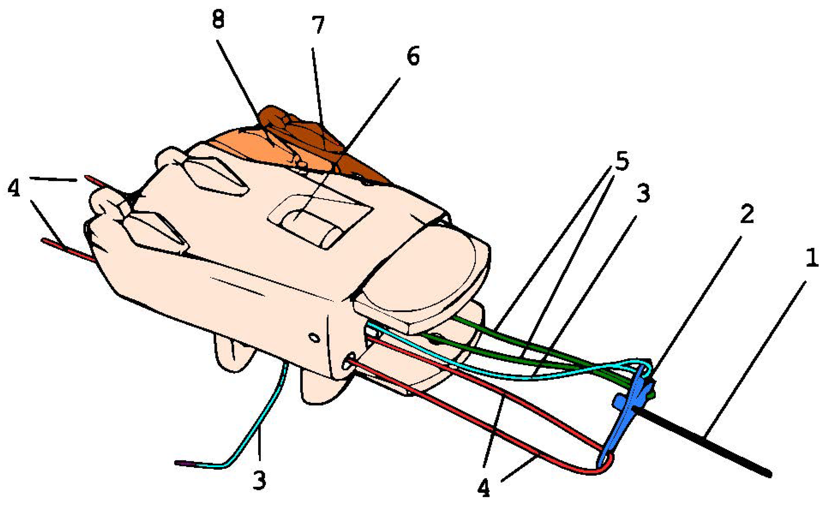
Our design uses a force distribution mechanism to distribute the pulling force from the user to all five fingers. There are some patents and inventions that are similar to our work.
Belter et al. [14], under US patent number 20170049583, designed a prototype that uses intertwined ropes to distribute the forces to the fingers. However, the thumb is not a part of the grasping mechanism and is only used cosmetically.
The design of Trusaji et al. [15], under Indonesian patent number P00202007576, uses a triangle-shaped link which has a shape similar to a pulley on both of its ends. However, that design distributes force only to the four fingers, as there is no thumb attached.
Aleksandrovich [16], under Russian patent RU2664171C1, proposed a balancing mechanism using two linked pulleys arranged in parallel and connected by a rod, which is linked to a pulley with a series arrangement. The five fingers, including the thumb, are linked to the balancing mechanism in the patent. Nevertheless, the parallel and series arrangement of the three pulleys complicates the component assembly process within the prosthetic hand’s limited space. The structure also causes the thumb to bend first, before the other four fingers.
In a healthy hand, humans either move the five fingers simultaneously, or the four fingers first before the thumb when grasping something unconsciously. We designed a system that tries to emulate the simultaneous movements of the five fingers to create an adaptive grasp.

3. System Design

Our design consists of three main parts: the force distributor, the main hand, and the finger mechanism. The force distributor uses ropes to distribute the pulling force from the user to all five fingers. The main hand consists of a palm, a fourth metacarpus, and a fifth to accommodate the grasped object’s contours and shapes. The fingers use pulleys that act as the joints, elastic rope as the extensor muscle tendon, and non-elastic rope as the flexor muscle tendon. Figure 1 illustrates our designed prosthetic hand’s overall top-view block diagram, showing a right-hand design.
Figure 2 shows the detailed parts of our designed prosthetic hand. The parts labeled 1 to 5 are the force distribution subsystem, parts 6 to 8 are the main hand subsystem, and parts 9 to 13 are the fingers subsystem. We will explain the design of each part in the following subsections.

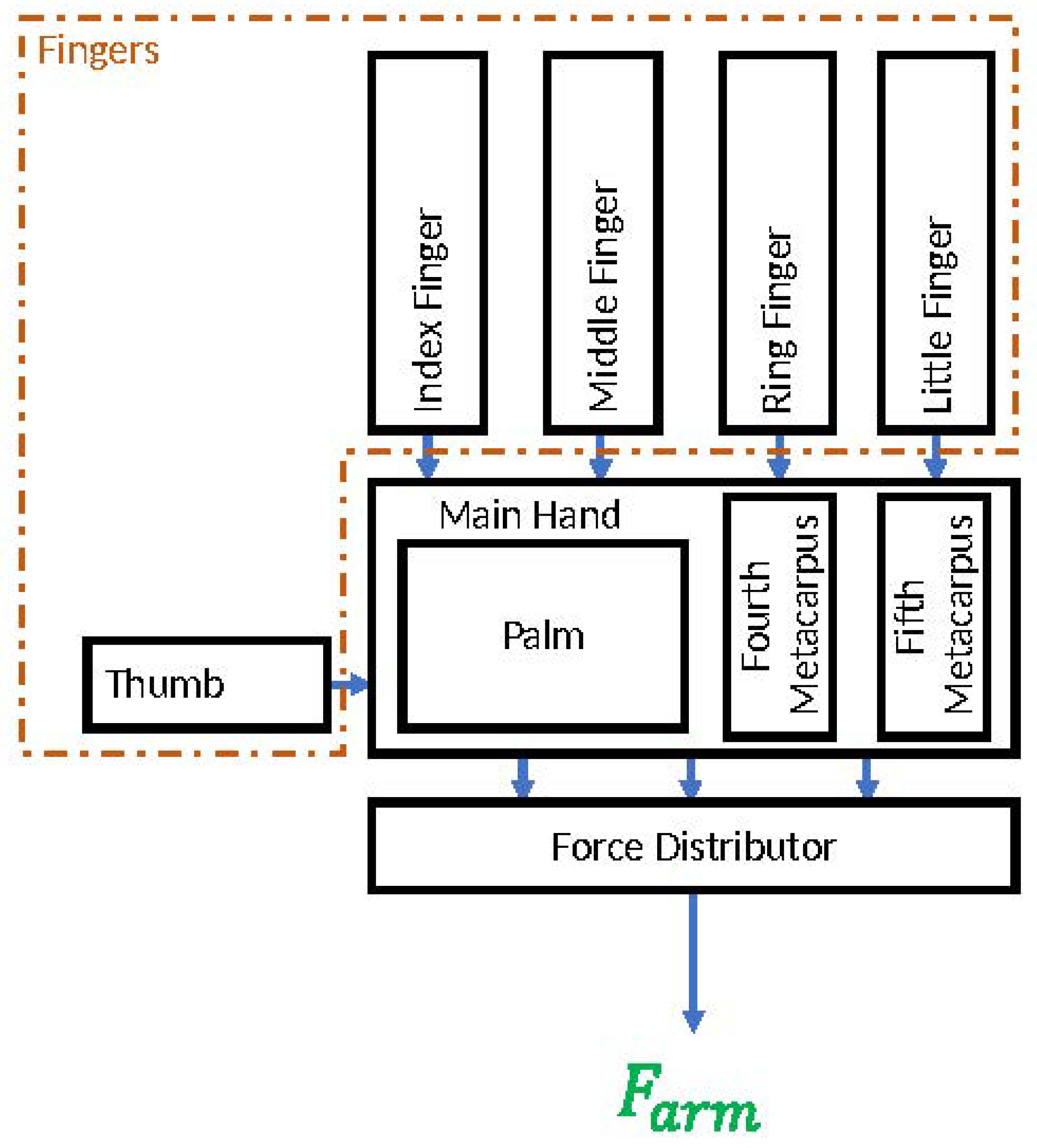
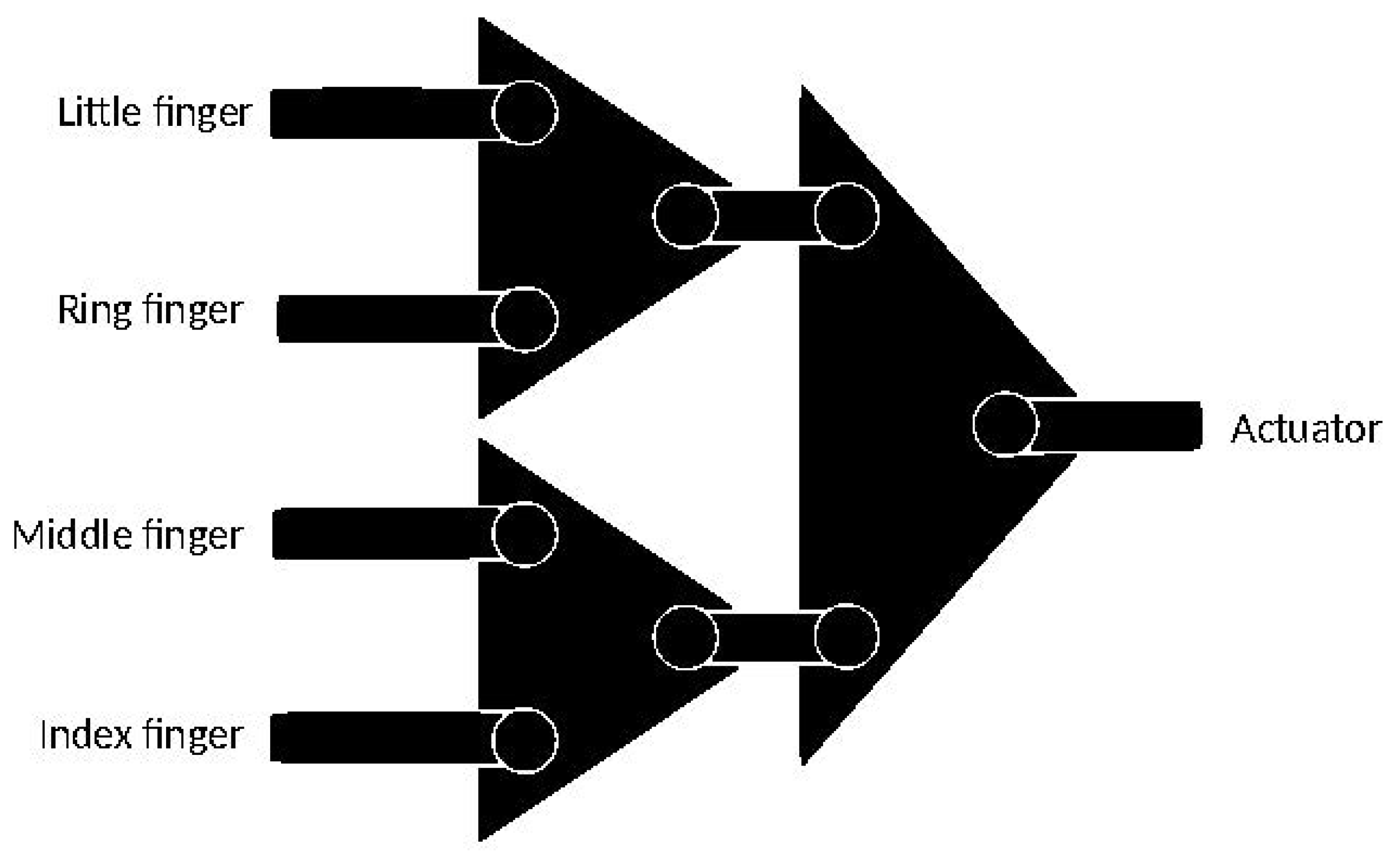
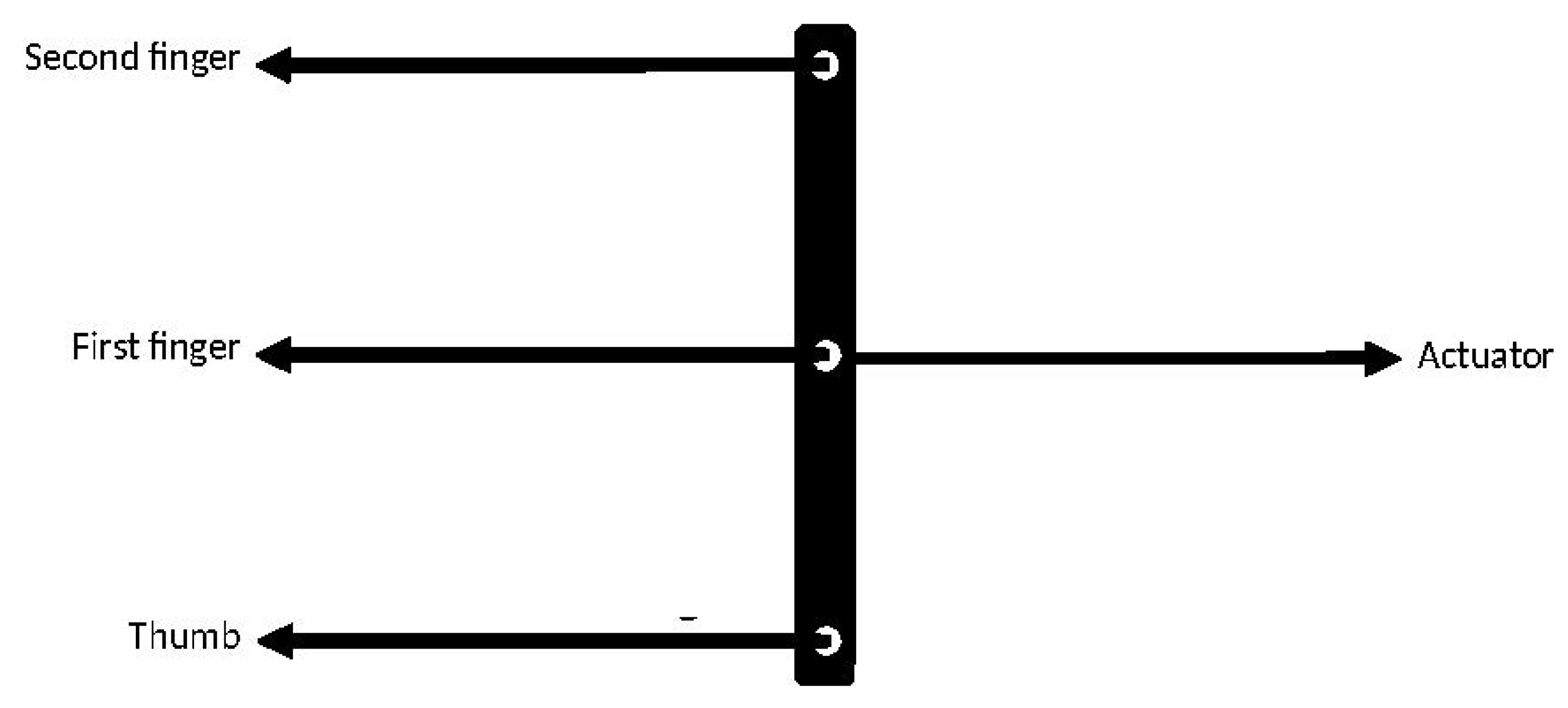
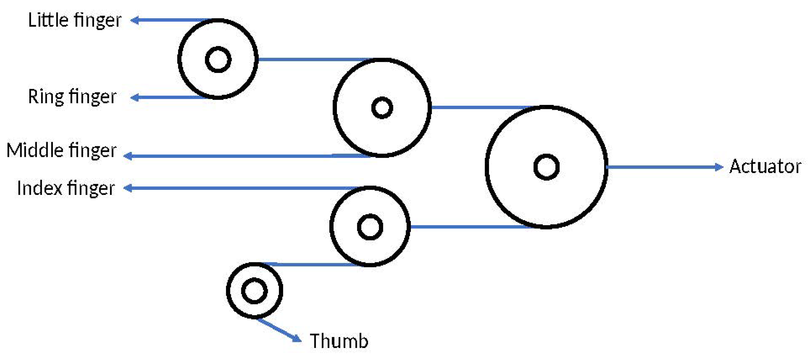
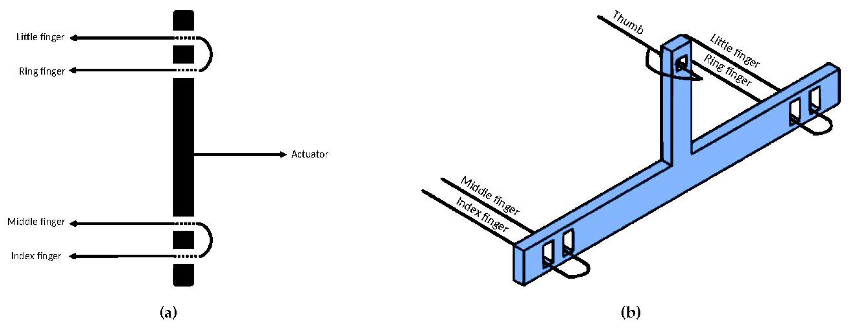
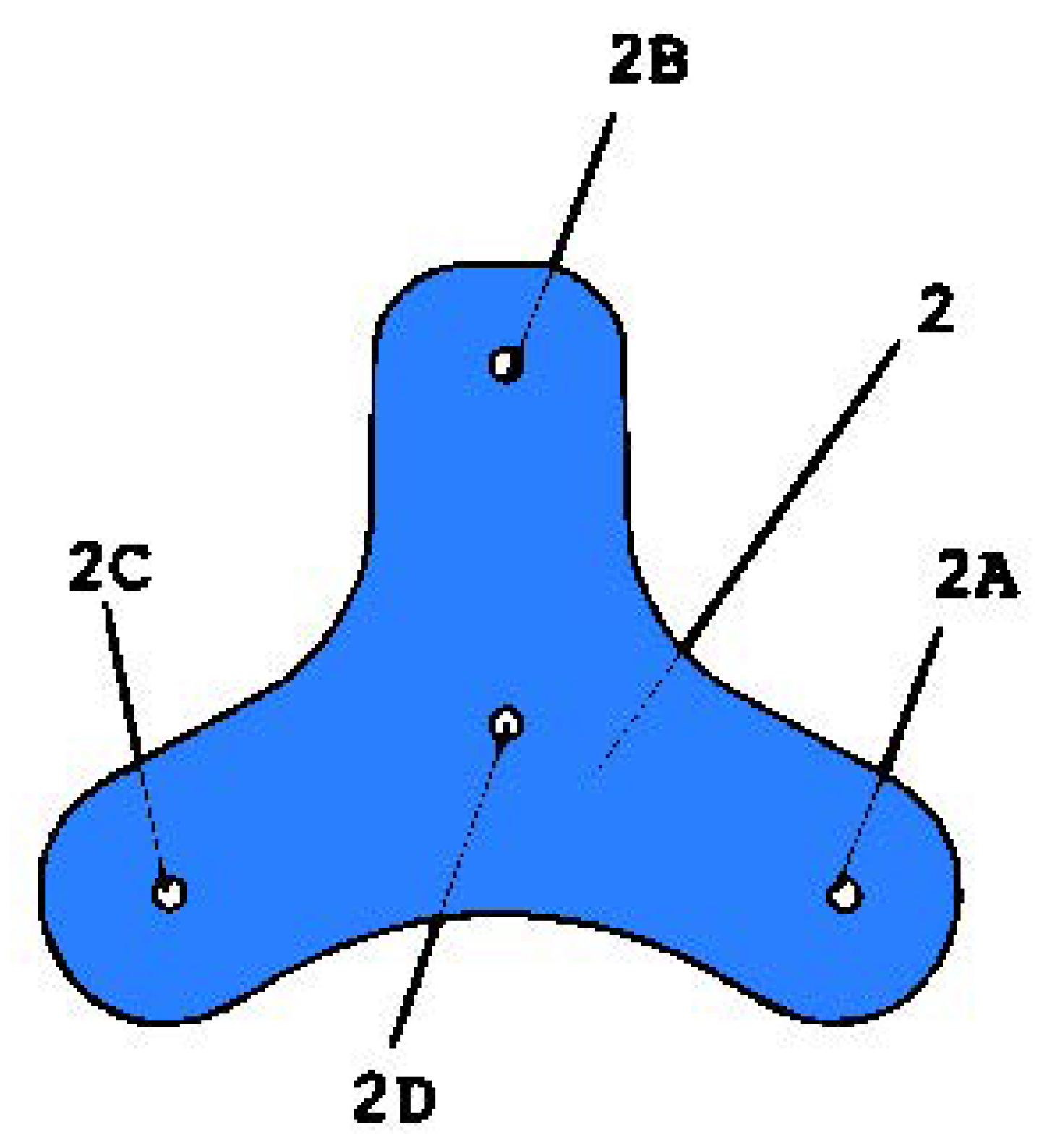
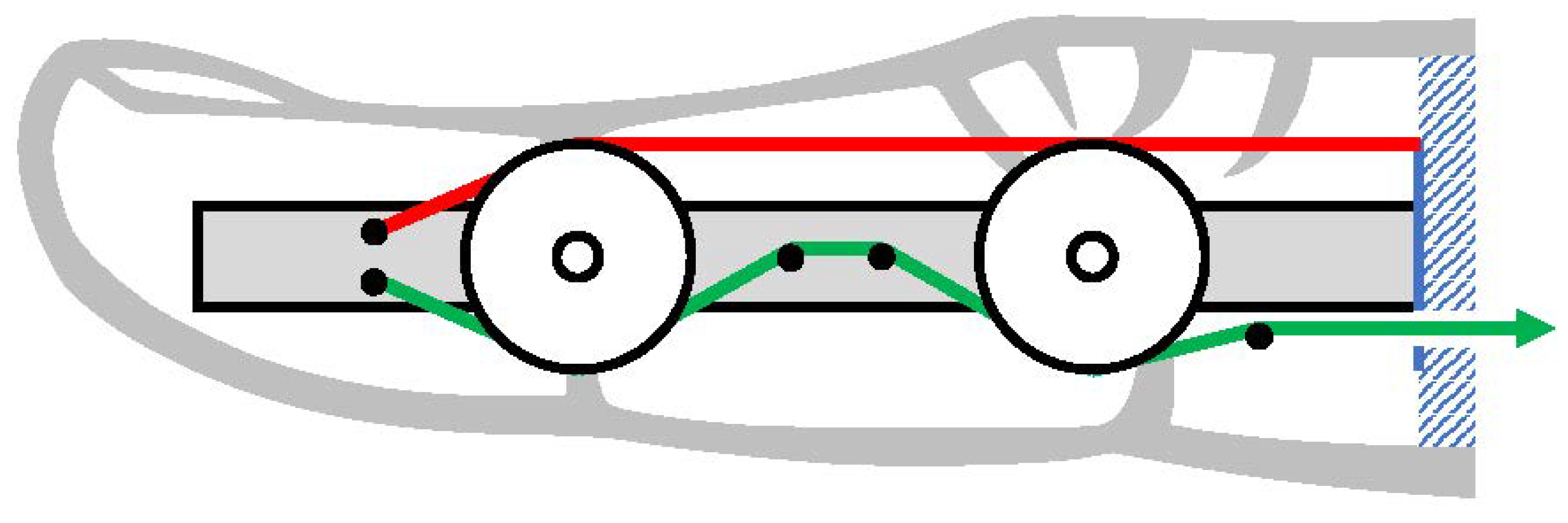
3.1. Force Distributor

The main idea of our hand design was to minimize the number of parts and actuators to use as few components as possible. We designed a system to transform a simple pull of the main rope into a grasping motion. One of the most crucial subsystems in a prosthetic hand device is the one distributing the pulling force into each finger.

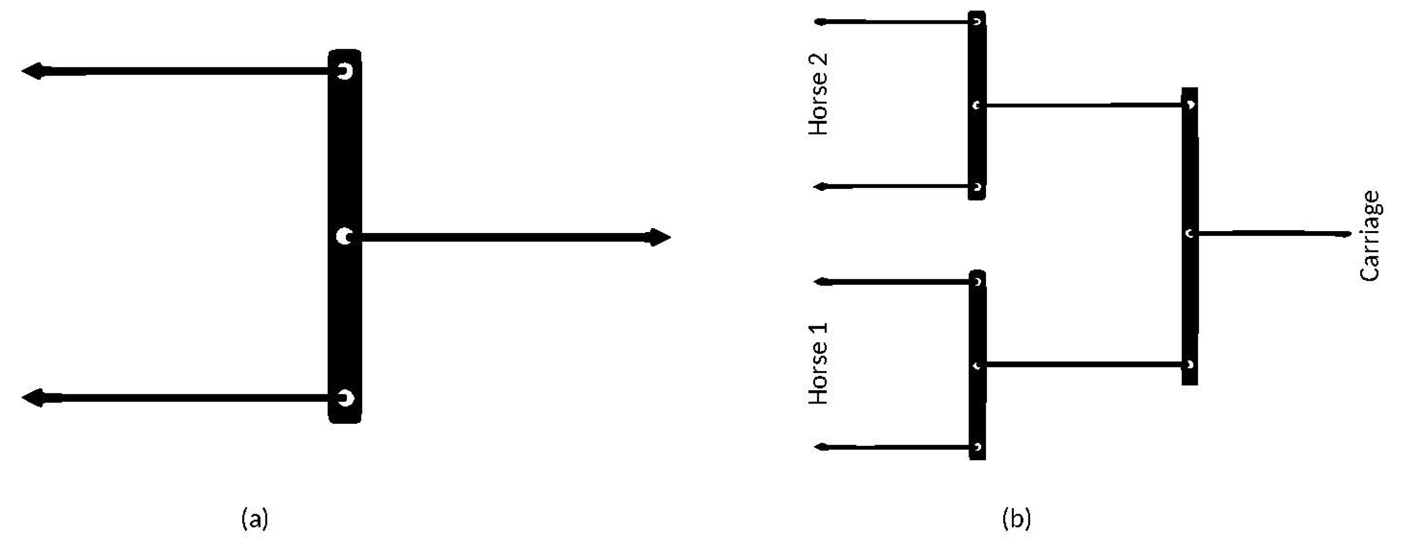
3.1.1. Force Distributor Review

Designing a force distribution system is not an easy task [17]. One of the solutions is using a whippletree-like mechanism. A whippletree is a mechanical device used in horse-drawn vehicles to transfer the pulling force of the horses to the vehicle. It consists of a series of bars or rods hinged together, with one end attached to the horses’ harnesses and the other end attached to the vehicle. The design allows the horses to pull in a straight line rather than at an angle, which helps to distribute the force more evenly and reduces strain on the horses.
The most common of this whippletree mechanism examples is a two-horse team for pulling a carriage. In the two-horse team, three bars are used to distribute a force between two horses to share the work evenly. This arrangement is sometimes known as a double-tree. Figure 3 illustrates the basic elements of the whippletree and double-tree arrangement schematic in the two-horses team.
In the hand prosthesis design, a whippletree-like mechanism is very useful to minimize the number of actuators. Instead of controlling each finger with multiple actuators, the whippletree mechanism distributes forces evenly from one actuator to the fingers. Thus, the whippletree mechanism can mechanically adjust the movement of fingers according to the shape of the object. This feature is achieved by regulating the force transmission into each finger based on the amount of resistance given by the object to each finger.
There are a few previously designed prosthetic hands that use whippletree-like mechanisms. A prosthetic hand designed by Groenewegen [18] uses a mechanism called a whippletree to allow for an adaptable grasping function. This mechanism consists of seven bars, three triangle-shaped bars, and nine pins arranged in a double-tree configuration. All of these components were 3-D printed. The design of Groenewegen’s whippletree is shown in Figure 4.
Makerhand [19] proposed a prosthetic hand that has a unique approach. It has only three fingers, including the thumb. The three-finger configuration arose since it considers the most basic whippletree arrangement, which consists of only one bar and four lines. The design only uses one bar and three lines to achieve a whippletree mechanism for its prosthetic hand. The line from three fingers is attached to each tip of the bar and the center of the bar. Figure 5 illustrates the schematic of Makerhand’s whippletree mechanism.
Esposito et al. [20] proposed the "Federica" hand, which uses multiple pulleys and ropes to implement its whippletree mechanism to distribute force to all five fingers. However, the numbers of pulleys and ropes make the force distributed to the fingers uneven and less than ideal. Figure 6 shows the pulley-whippletree configurations of Federica.

3.1.2. Force Distribution Design

Learning from the disadvantages of the previous whippletree systems [18,19,20] that only used less than five fingers, sacrificing the amount of force distributed to the fingers, or using too many parts, we designed a system that is able to:
  • Distribute the force to all the fingers;
  • Maximize the force distributed to the fingers.
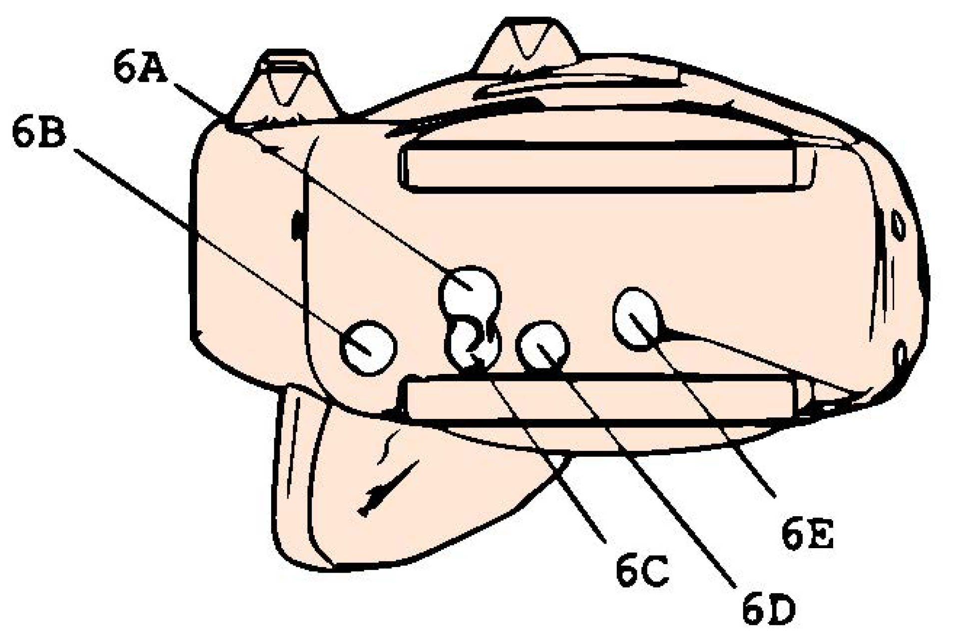
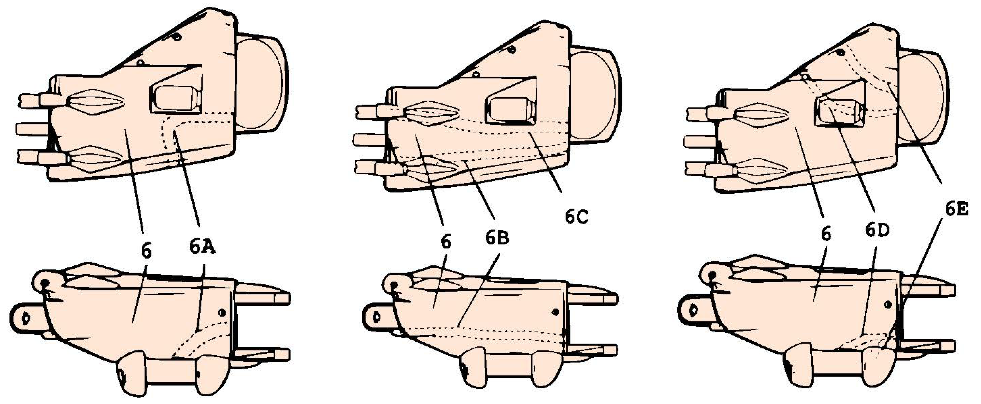
Our design was inspired by the pulley-and-rope system. However, one of our goals was to minimize the number of parts. Therefore, we replaced the pulley with a pin-based whippletree system. The initial design of this idea in 2-dimensional space can only work with four fingers without an additional bar for the thumb. Keeping in mind that minimizing the number of parts is our priority, we exploited the 3-dimensional space to add a pin for the thumb. This design only needs one bar. Figure 7 shows the initial design in 2-dimensional space and 3-dimensional space for the addition of the thumb.
We then simplify the design of the bar as a propeller or fidget-spinner-like shape, as shown in Figure 8. This simplification is done to get a more symmetrical and balanced shape while also reducing the number of small pins or holes. The edge of the balancer acts as the second pin for both index–middle-finger and ring–little-finger pairs.
We call this novel force-balancing whippletree-like mechanism Versatile Gripping Technology (VGT) which we patented at the Indonesian Patent Office [21]. However, this whippletree connector also has a disadvantage: it requires more space and larger arm sockets.

3.2. Main Hand

The next important subsystem is the main hand, which consists of three parts: the palm, the fourth metacarpus, and the fifth metacarpus. We chose this mechanism to facilitate a spherical grip by simulating the upper part of palmar creases. Together, they form the main hand subsystem that can adapt to the grasped object shape. Figure 9 shows the integrated isometric view of both the force distributor and the main hand subsystem.
They also have an important role in the rope routing for distributing and directing the pulling force, especially for the thumb. The thumb is a special feature because it rotates in the yaw direction while the other fingers rotate in the pitch direction. Therefore, it is attached to the side of the palm and requires special routing. Figure 10 illustrates the back view of the palm. We also marked the holes where we inserted the ropes from the force-distribution mechanism.
Figure 11 shows the inner palm channels of each finger. The palm is connected directly to the thumb, index finger, and middle finger. For the ring and little finger, we first route the rope to additional parts—the fourth and fifth metacarpals—to accommodate an adaptive grasp.
In the fourth and fifth metacarpal parts, the palm ropes go to their channels before finally being connected to the ring and little fingers. Figure 12 shows the routing channels of the aforementioned parts.
Using this main hand design, we can distribute the pulling force to all the connected fingers while providing an adaptive grasp by adding flexible fourth and fifth metacarpal parts. The rope is then connected to the fingers, which we discuss in the following section.

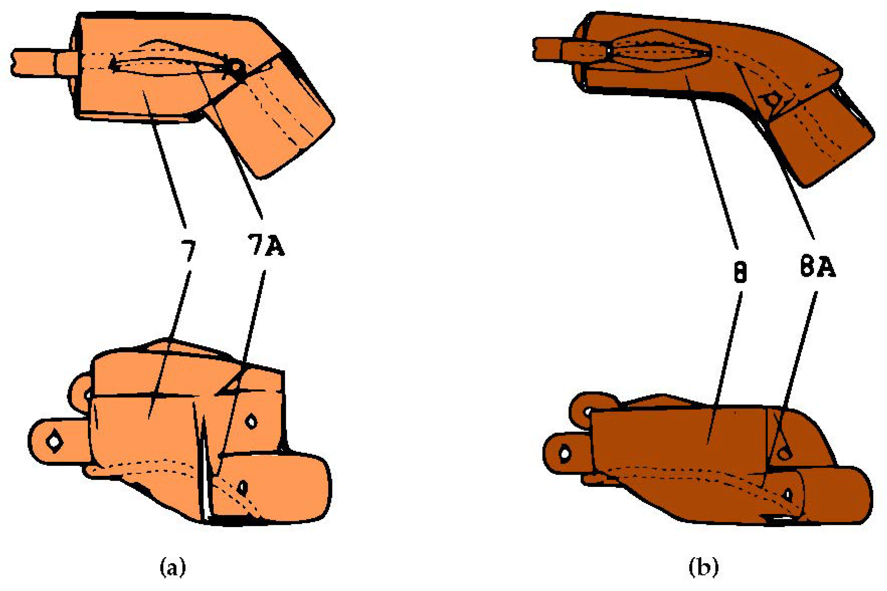
3.3. Fingers’ Mechanism

We surveyed a few possible mechanisms for the fingers’ mechanism: the compliant mechanism [22], 4-bar linkage [23], and pulley–line mechanism [24]. We then compared the advantages and disadvantages of each mechanism. Table 1 shows the pros and cons list for each mechanism.
We chose to use the fingers’ mechanism based on what we value most in our design: cost, availability, and simplicity. We decided to use the pulley–line mechanism in our design.
Each of the ropes from the main hand mechanism is connected to each finger. In this part, the mechanism uses two pulleys, three rods, an elastic rope, and a non-elastic rope. The non-elastic ropes are the continuation of the rope from the main hand. Figure 13 shows how we arrange the rods, pulleys, and ropes in their resting state.
The two pulleys act as the metacarpophalangeal (MP) joint and distal-interphalangeal (DIP) joint. The elastic rope acts as the extensor muscle tendon, and the non-elastic rope acts as the flexor muscle tendon. When the flexor rope is pulled by the forces, F r , from the main hand, the fingers will make a grasping motion, and the extensor rope will be stretched, as shown in Figure 14.
When the pulling force is released, the elasticity of the extensor rope will force the fingers back to their resting positions. For simplicity of the production, we also designed the thumb with three knuckles, unlike a real hand, in which the thumb only has two knuckles. The finger mechanisms are then packaged into finger-like detachable parts, as shown in Figure 2.

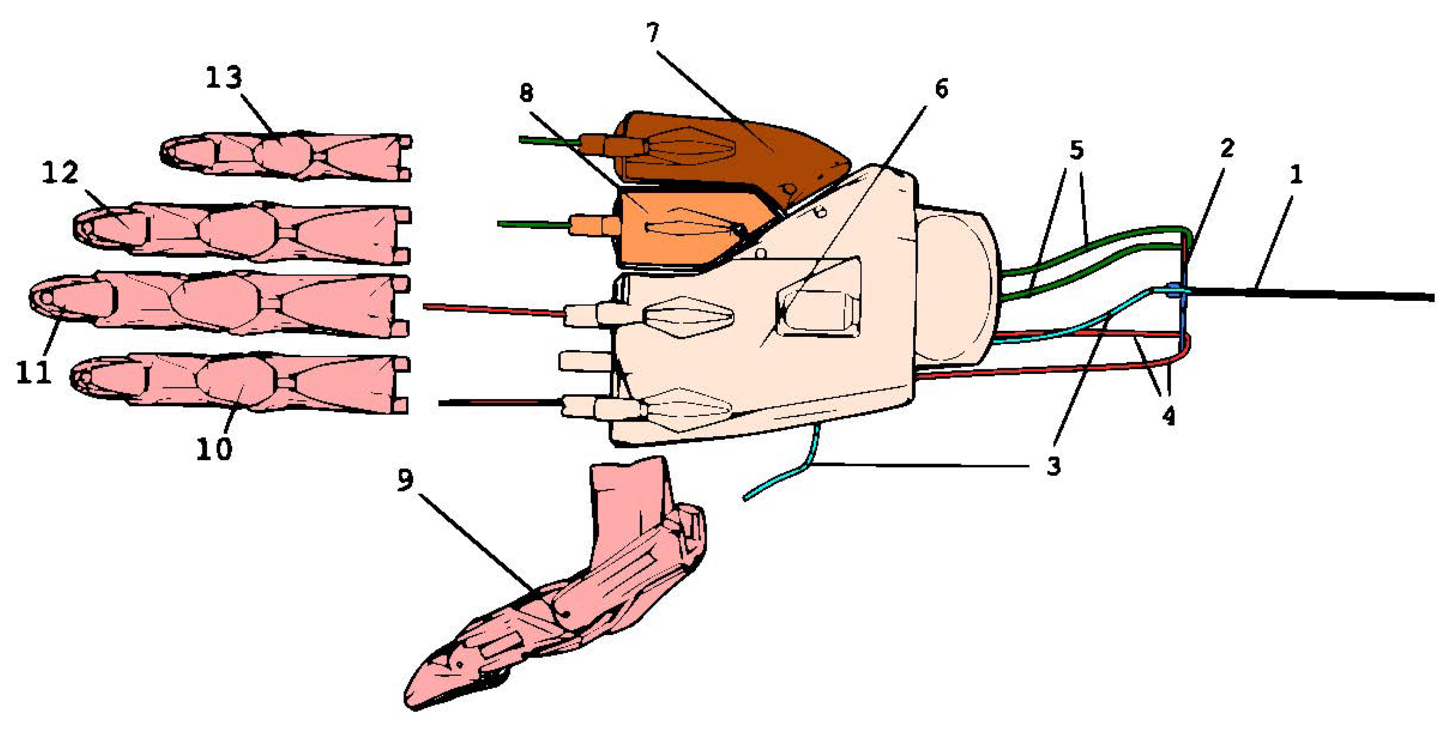
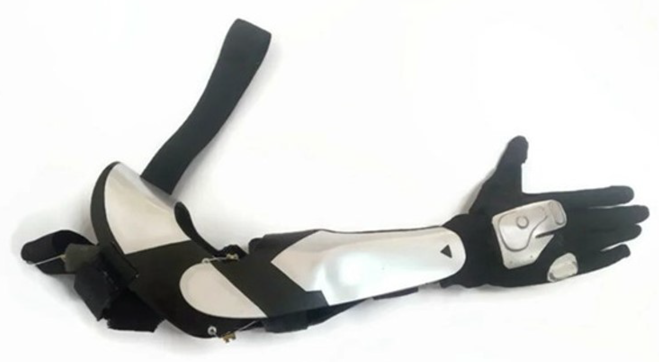
3.4. Prototype Production and Packaging

We used 3-D printing technologies to make the non-moving parts of our design, which consist of the force distributor, palm, fourth and fifth metacarpal bones, and the fingers’ parts: rods and pulleys. The complete hand was then covered in a textured leather glove to increase friction and make it easier to grasp objects.
All the designing of parts was done in Blender (https://www.blender.org/, accessed on: 1 December 2022),and the material used for 3-D printing was acrylonitrile butadiene styrene (ABS). The main pulling rope was made of a Bowden cable, the elastic rope for the fingers tendon was a crafting elastic rope, and the non-elastic rope was made of a high-grade fishing line. Table 2 shows our bill of materials for our design.
We also designed a casing for the lower and upper arms [25], which we designed to give a comfortable feeling to the user. Figure 15 shows the complete packaging of our design for the right hand. We also produced a left-handed version of the prototype.

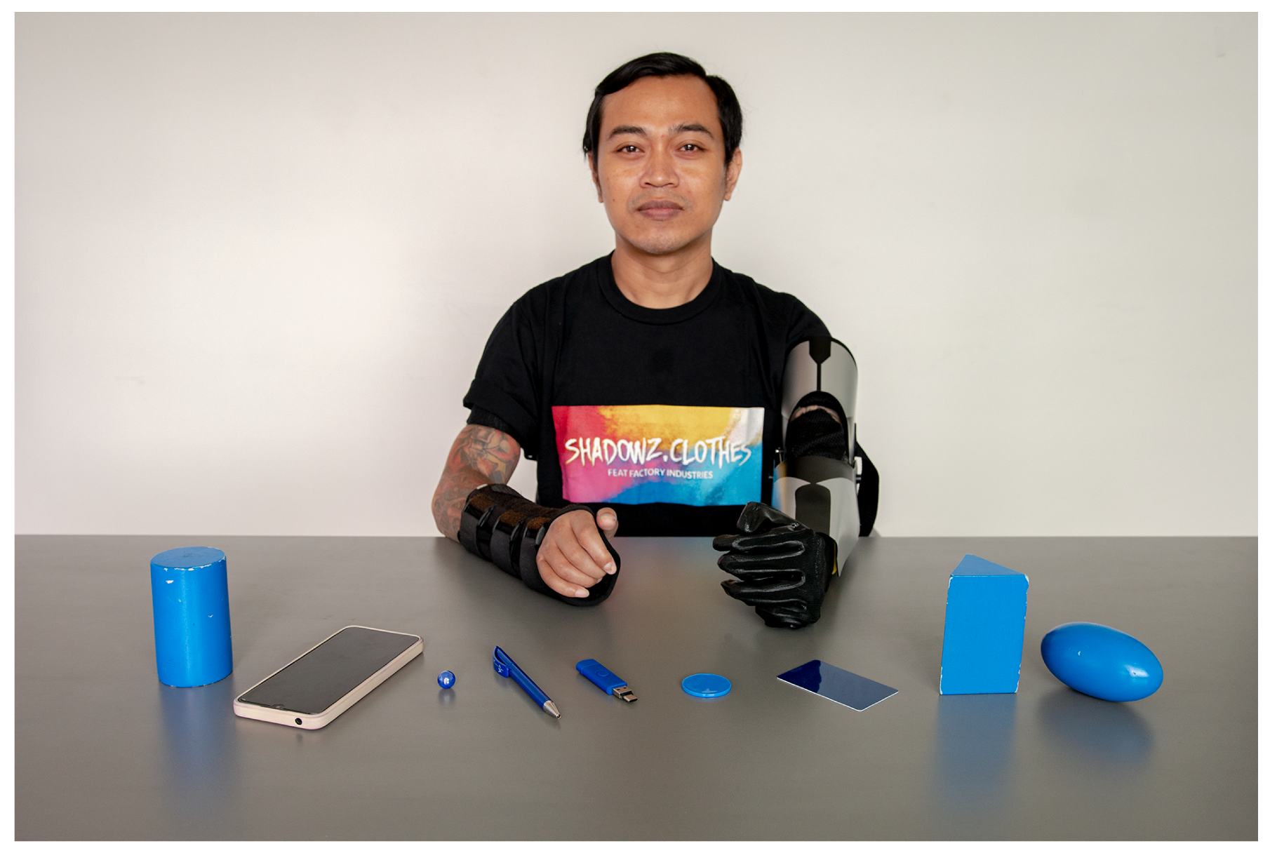
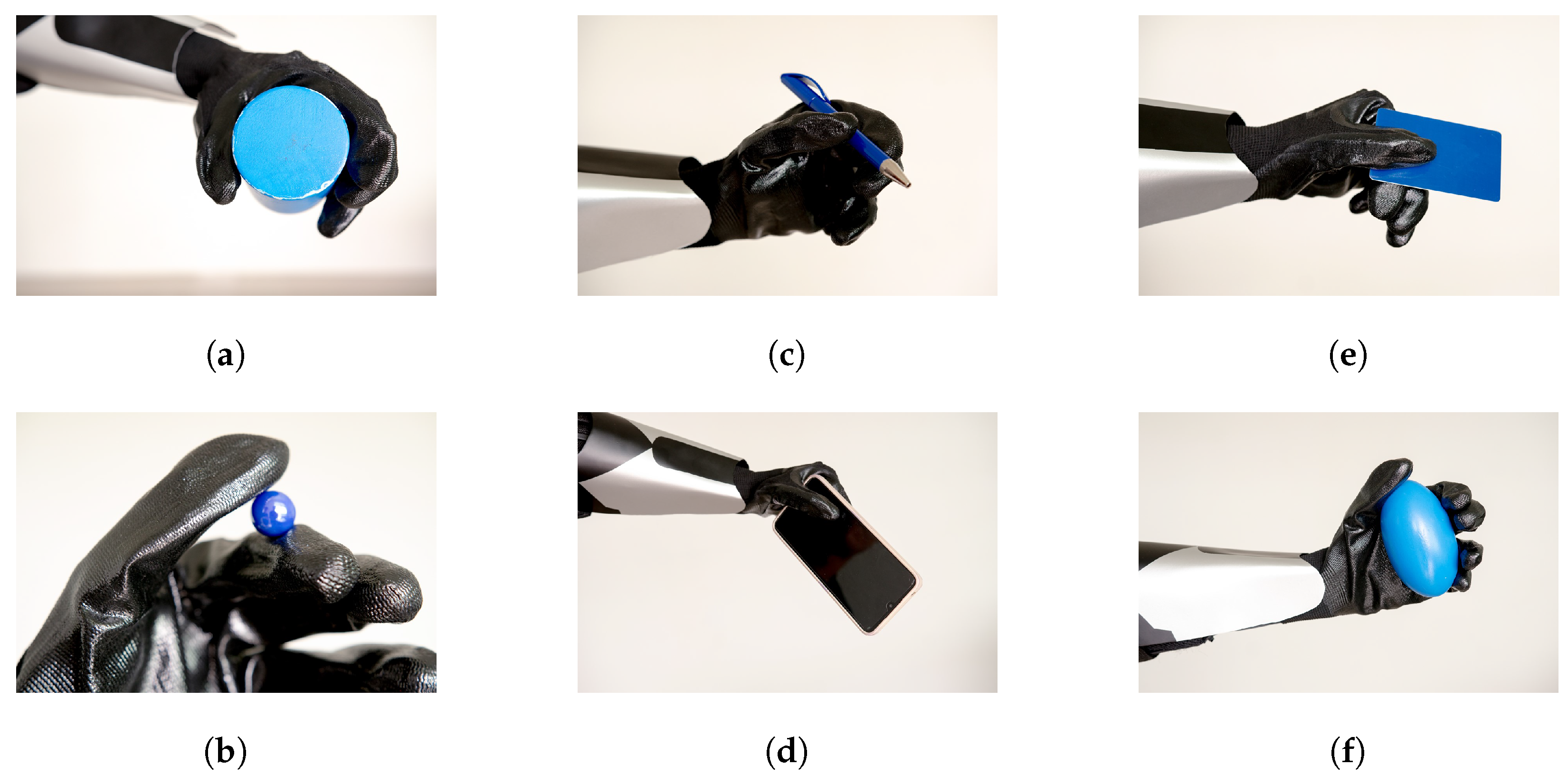
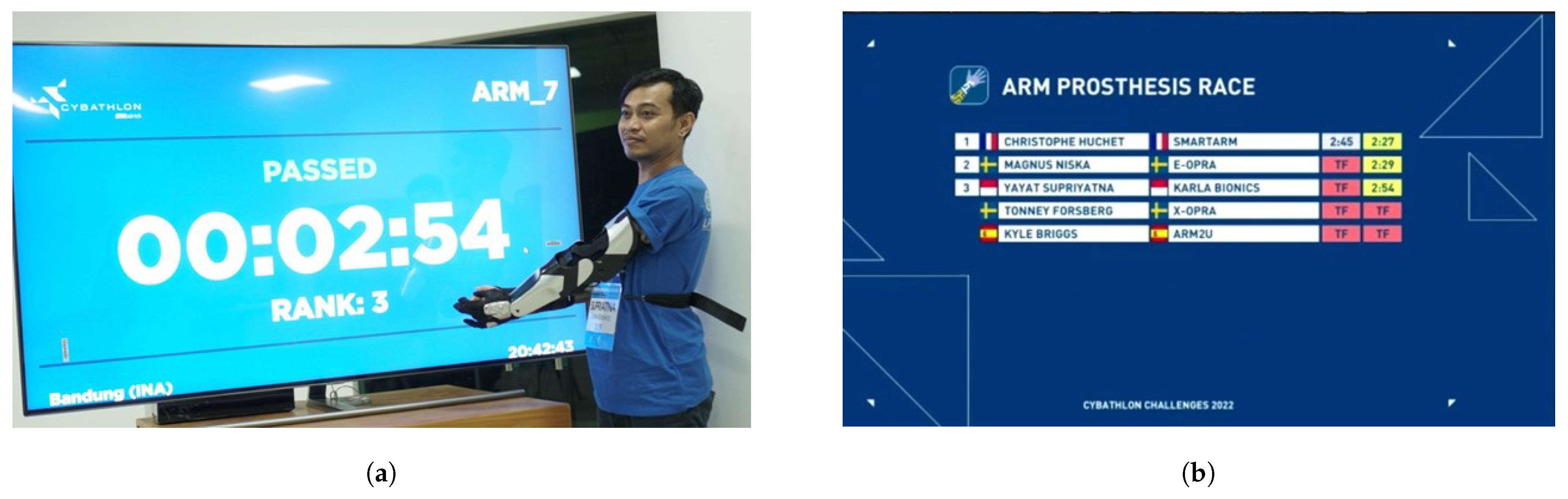
4. Results and Performance Evaluations

The evaluate the grasping capabilities of our design, we used the Southampton Hand Assessment Procedure (SHAP) [26], which is a standardized assessment tool used to evaluate the function of the hands and upper extremities of individuals with hand impairments or disabilities.
We tried the design to grip various objects by performing tip gripping, lateral gripping, tripod gripping, spherical gripping, power gripping, and extension gripping. Figure 16 shows our pilot, a left-hand amputee wearing our left-hand prototype version, ready to grasp various objects: a cylinder, a smartphone, a pen, a USB stick, a jar lid, a credit card, a triangular prism, and an egg-shaped object.
Our pilot was capable of driving our design to form various grips according to the SHAP: a power grip by holding the cylinder, a tip grip by holding a marble, an extension grip by holding a smartphone, and a spherical grip by holding an egg-shaped object. Figure 17 shows our documentation of our pilot holding various objects. The limitation of our technology is it can not form a tripod grip, which a healthy hand typically makes when writing. However, we would argue that, in our case, a tripod grip can be replaced by a tip grip for holding objects such as pens. This is also supported by the fact that our prosthetic hand is not designed to perform complex movement tasks, such as writing or eating with chopsticks.
We conclude that our design worked as intended: providing an affordable body-powered prosthetic hand that is affordable; simple to use—by just pulling the main rope, it will produce a grasping motion; uses a minimum number of parts; is easily prototyped; and can be mass-produced locally. In the city where we are located, we can obtain all the materials at an affordable price, and we have access to 3-D printing facilities that can fulfill our production demand. The overall production cost of our design is less than $1000, which is still in the affordable range.
To test our design further, we participated in the Cybathlon Challenge 2022, a hand prosthetic race competition held by ETH Zürich, Switzerland, on 17 May 2022. The competitors were asked to move various objects from one table to another with obstacles against time. All participants were then sorted by their time. Our pilot won third place in the competition, as shown in Figure 18 [27,28].
We also collected testimonial from our user about the use of our prototype in daily life:
  • It can help with daily necessities, such as sweeping the floor, putting the laundry on a drying rack; and also can help with playing sports confidently.
  • It can be a starting point for a conversation in a public place, such as a train or bus, which helps in gaining more confidence.

5. Comparison to Other Works

There are many well-developed branches of 3-D printed prosthetic hand that have been researched before. To assess our contributions to existing research, we compare the advantages and disadvantages of our design to similar prototypes available. Table 3 shows the advantages and disadvantages compared to other prosthetic hands.

6. Conclusions and Future Works

In this paper, we presented a simple and affordable prosthetic hand, which we named Karla. The design provides an affordable body-powered prosthetic hand that is affordable, simple, uses a minimum number of parts, and is easily produced. The designed hand, Karla, is capable of creating five of six grips in the SHAP hand assessment: the power grip, tip grip, extension grip, lateral grip, and spherical grip.
We also see an opportunity to develop a future design improvement. In our present design, the main actuator is a rope pulled by the user’s healthy hand. We are currently working on developing a sensor–actuator system that is able to electronically or mechanically pull the main rope of the system by trying various sensors, such as electromyography (EMG) sensors and force-sensitive resistors (FSR), and then processing the signals into meaningful data that can control a servo motor to pull the main rope.

Author Contributions

This work was realized through the collaboration of all authors. Conceptualization, W.T., E.N. and R.Z.G.; methodology, W.T.; investigation, W.T. and A.S.; resources, W.T., D.I., A.S. and C.S.; data curation, A.S.; writing—original draft preparation, A.S.; writing—review and editing, A.S.; visualization, A.S.; supervision, D.I. and C.S.; project administration, W.T. and I.A.; funding acquisition, W.T., A.S., I.A. and C.S. All authors have read and agreed to the published version of the manuscript.

Funding

The study was the result of start-up funding of “Lembaga Pengembangan Inovasi dan Kewirausahaan (LPIK)” of Institut Teknologi Bandung (ITB).

Data Availability Statement

Not available.

Conflicts of Interest

The authors declare no conflict of interest.

Abbreviations

The following abbreviations are used in this manuscript:
DIPDistal-interphalangeal
EMGElectromyography
FSRForce-sensitive resistor
MPMetacarpophalangeal
SHAPSouthampton Hand Assessment Procedure
VGTVersatile Gripping Technology

References

  1. Jang, C.H.; Yang, H.S.; Yang, H.E.; Lee, S.Y.; Kwon, J.W.; Yun, B.D.; Choi, J.Y.; Kim, S.N.; Jeong, H.W. A survey on activities of daily living and occupations of upper extremity amputees. Ann. Rehabil. Med. 2011, 35, 907–921. [Google Scholar] [CrossRef] [PubMed]
  2. Holzer, L.A.; Sevelda, F.; Fraberger, G.; Bluder, O.; Kickinger, W.; Holzer, G. Body image and self-esteem in lower-limb amputees. PLoS ONE 2014, 9, e92943. [Google Scholar] [CrossRef] [PubMed] [Green Version]
  3. Gaine, W.; Smart, C.; Bransby-Zachary, M. Upper limb traumatic amputees: Review of prosthetic use. J. Hand Surg. 1997, 22, 73–76. [Google Scholar] [CrossRef]
  4. Saradjian, A.; Thompson, A.R.; Datta, D. The experience of men using an upper limb prosthesis following amputation: Positive coping and minimizing feeling different. Disabil. Rehabil. 2008, 30, 871–883. [Google Scholar] [CrossRef]
  5. Biddiss, E.A.; Chau, T.T. Upper limb prosthesis use and abandonment: A survey of the last 25 years. Prosthetics Orthot. Int. 2007, 31, 236–257. [Google Scholar] [CrossRef] [PubMed]
  6. Maat, B.; Smit, G.; Plettenburg, D.; Breedveld, P. Passive prosthetic hands and tools: A literature review. Prosthetics Orthot. Int. 2018, 42, 66–74. [Google Scholar] [CrossRef] [PubMed] [Green Version]
  7. Castellini, C. Upper limb active prosthetic systems—Overview. Wearable Robot. 2020, 365–376. [Google Scholar]
  8. Millstein, S.; Heger, H.; Hunter, G. Prosthetic use in adult upper limb amputees: A comparison of the body powered and electrically powered prostheses. Prosthetics Orthot. Int. 1986, 10, 27–34. [Google Scholar] [CrossRef] [PubMed] [Green Version]
  9. Carroll, R.; Carrozza, B.; Lopez, J.; Ordonez, Y.; Sanchez, E.; Kim, D.; Lee, A.; Teh, K.S. Accessible Children’s Prosthetics Created Using 3D Printing Technologies 2018. Available online: https://canadacollege.edu/stemcenter/images/aspiresintern2017/ME-paper.pdf (accessed on 1 December 2022).
  10. Ten Kate, J.; Smit, G.; Breedveld, P. 3D-printed upper limb prostheses: A review. Disabil. Rehabil. Assist. Technol. 2017, 12, 300–314. [Google Scholar] [CrossRef] [PubMed]
  11. Harkins, C.S.; McGarry, A.; Buis, A. Provision of prosthetic and orthotic services in low-income countries: A review of the literature. Prosthetics Orthot. Int. 2013, 37, 353–361. [Google Scholar] [CrossRef] [PubMed]
  12. Carey, S.L.; Lura, D.J.; Highsmith, M.J. Differences in myoelectric and body-powered upper-limb prostheses: Systematic literature review. J. Rehabil. Res. Dev. 2015, 52. [Google Scholar] [CrossRef] [PubMed]
  13. Resnik, L.; Meucci, M.R.; Lieberman-Klinger, S.; Fantini, C.; Kelty, D.L.; Disla, R.; Sasson, N. Advanced upper limb prosthetic devices: Implications for upper limb prosthetic rehabilitation. Arch. Phys. Med. Rehabil. 2012, 93, 710–717. [Google Scholar] [CrossRef] [PubMed]
  14. Belter, J.; Dollar, A.; Leddy, M. Multi-Grasp Prosthetic Hand. US Patent 20170049583, 2016. [Google Scholar]
  15. Trusaji, W.; Hammam, S. Alat Penggerak Jari Untuk Menghasilkan Genggaman Adaptif Dan Efisien Pada Lengan Prostetik (English: Design of Finger Mechanism to Produce An Adaptive and Efficient Grip in Prostethic Hand). Indonesian Patent P00202007576, 2020. pp. 1–15. [Google Scholar]
  16. Aleksandrovich, L.M. Arm Prosthesis for Patients with the Degree of Amputation From Fingers to the Forearm, Prosthesis of the Wrist Joint, Which Includes The Hand Prosthesis, the Finger Rod Cable Locking Device of the Hand Prosthesis (3 Options), the Finger Position Combination Control Device of the Hand Prosthesis (2 Options). Russian Patent RU2664171C1, 2018. [Google Scholar]
  17. Trusaji, W.; Irianto, D.; Satriawan, A.; Setianingsih, C.; Nurtriandari, E.; Geosasi, R.Z. Design Process of Whippletree-Like Mechanism for Versatile Gripping in Arm Prosthesis 2022. Available online: https://www.preprints.org/manuscript/202210.0011/v1 (accessed on 1 December 2022).
  18. Groenewegen, M. Design of a Compliant, Multi-Phalanx Underactuated Prosthetic Finger. Ph.D. Thesis, Delft University of Technology, Delft, The Netherlands, 2014. [Google Scholar]
  19. Dukij, A. Makerhand. Available online: https://www.makerhand.com/ (accessed on 25 December 2022).
  20. Esposito, D.; Savino, S.; Andreozzi, E.; Cosenza, C.; Niola, V.; Bifulco, P. The “Federica” Hand. Bioengineering 2021, 8, 128. [Google Scholar] [CrossRef] [PubMed]
  21. Trusaji, W.; Hammam, S. Tangan prostetik bermekanisme penggerak adaptif untuk kelima jari serta memiliki metakarpus keempat dan kelima (English: Prosthetic hand with an adaptive grip mechanism with fourth and fifth metacarpal). Indonesian Patent P00202101141, 2021. pp. 1–15. [Google Scholar]
  22. Toro-Ossaba, A.; Tejada, J.C.; Rúa, S.; López-González, A. A Proposal of Bioinspired Soft Active Hand Prosthesis. Biomimetics 2023, 8, 29. [Google Scholar] [CrossRef] [PubMed]
  23. Abdul Wahit, M.A.; Ahmad, S.A.; Marhaban, M.H.; Wada, C.; Izhar, L.I. 3D Printed Robot Hand Structure Using Four-Bar Linkage Mechanism for Prosthetic Application. Sensors 2020, 20, 4174. [Google Scholar] [CrossRef] [PubMed]
  24. Sainul, I.; Deb, S.; Deb, A. A three finger tendon driven robotic hand design and its kinematics model. In CAD/CAM, Robotics and Factories of the Future; Springer: Berlin/Heidelberg, Germany, 2016; pp. 313–321. [Google Scholar]
  25. Trusaji, W.; Hammam, S. Soket Untuk Lengan Prostetik Yang Dapat Disesuaikan Dengan Ukuran Dan Kontur Puntung Lengan Serta Mampu Memindahkan Kalor Dari Puntung Lengan Ke Udara (English: Size-and-Contour Adaptive Prosthetic Arm Socket Capable Of Releasing Heat to the Air). Indonesian Patent P00202205996, 2022. pp. 1–15. [Google Scholar]
  26. Kyberd, P.J.; Murgia, A.; Gasson, M.; Tjerks, T.; Metcalf, C.; Chappell, P.H.; Warwick, K.; Lawson, S.E.; Barnhill, T. Case studies to demonstrate the range of applications of the Southampton Hand Assessment Procedure. Br. J. Occup. Ther. 2009, 72, 212–218. [Google Scholar] [CrossRef]
  27. Karla Bionics in Cybathlon Challenge 2022. Available online: https://www.youtube.com/watch?v=iE5XzEyAOmg&t=48s/ (accessed on 25 December 2022).
  28. Permana, A. Karla Bionics in Cybathlon Challenge 2022. Available online: https://www.itb.ac.id/news/read/58685/home/karla-bionics-startup-wins-the-2022-international-cybathlon-challenge (accessed on 25 December 2022).
  29. Arm V2. Available online: https://www.thingiverse.com/thing:1131463 (accessed on 17 February 2023).
  30. Bionic Flexy Arm. Available online: https://www.thingiverse.com/thing:1768698 (accessed on 17 February 2023).
  31. NIOP Kwawu Remix. Available online: https://www.thingiverse.com/thing:3639854 (accessed on 17 February 2023).
  32. Unlimbited Armv2.1. Available online: https://www.thingiverse.com/thing:1672381 (accessed on 17 February 2023).
  33. Prótesis Personalizada Cinderella. Available online: https://www.thingiverse.com/thing:1768562 (accessed on 17 February 2023).
Figure 1. Overallblock diagram of Karla. The design consists of three parts: A force distributor, the main hand, and fingers. To make a grasping motion, the user pulls the main string with force F arm .
Designs 07 00037 g001
Figure 2. Complete illustration of the design: (1) Main rope. (2) Force distributor. (3) Thumb rope. (4) Index and middle finger rope. (5) Ring and little finger rope. (6) Palm. (7) Fifth metacarpus. (8) Fourth metacarpus. (9) Thumb. (10) Index finger. (11) Middle finger. (12) Ring finger. (13) Little finger.
Designs 07 00037 g002
Figure 3. Whippletree mechanism: (a) basic element of whippletree mechanism and (b) a double-tree arrangement in a two-horse team.
Designs 07 00037 g003
Figure 4. Whippletree mechanism proposed by Groenewegen [18].
Designs 07 00037 g004
Figure 5. Whippletree mechanism proposed by Makerhand [19].
Designs 07 00037 g005
Figure 6. "Federica"’s whippletree mechanism using a multiple-pulley system [20].
Designs 07 00037 g006
Figure 7. (a) Our initial design in 2-dimensional space and (b) 3-dimensional space design for the accommodation of the thumb.
Designs 07 00037 g007
Figure 8. Propeller or fidget-spinner-like whippletree bar. The numbering (2) follows the conventions in Figure 2. The hole (2A) and the edge of the design are used for the "pin" for the ring and little fingers. The hole (2B) is for the thumb. The hole (2C) works similarly to (2A) but for the index and middle finger. The hole (2D) is for the main rope to the arm direction.
Designs 07 00037 g008
Figure 9. The isometric view of the force distributor system (1–5) and main hand systems: (6) palm, (7) fifth metacarpus and (8) fourth metacarpus.
Designs 07 00037 g009
Figure 10. The back view of the palm. The holes are for inserting the rope into the channels and are connected to each finger. The (6A) hole is for the thumb; and the holes 6B–6E are for the index, middle, ring, and little fingers, respectively.
Designs 07 00037 g010
Figure 11. The top and left views of the palm show the routing channels, marked in dashed lines. Channel (6A) is for the thumb, channels (6B) and (6C) are directly connected to the fingers, channel (6D) is connected to the fourth metacarpus, and channel (6E) is connected to the fifth metacarpus.
Designs 07 00037 g011
Figure 12. (a) The routing channel (7A) for the fourth metacarpus and (b) the routing channel (8A) for the fifth metacarpus.
Designs 07 00037 g012
Figure 13. The arrangement of the rods, pulleys, and ropes inside the fingers. The elastic rope is shown in red, and the non-elastic pullable rope is shown in green.
Designs 07 00037 g013
Figure 14. The finger mechanism in the grasping position after a pulling force ( F r ) is applied.
Designs 07 00037 g014
Figure 15. The complete prosthetic hand after packaging, showing a right-hand design.
Designs 07 00037 g015
Figure 16. Our pilot wearing a left-handed version of Karla, ready to try grasping various objects.
Designs 07 00037 g016
Figure 17. Grasping various objects using our designed hand: (a) power grip, (b) tip grip, (c) tip grip as tripod grip replacement, (d) extension grip, (e) lateral grip, and (f) spherical grip.
Designs 07 00037 g017
Figure 18. Our pilot won third place in the Cyabathlon Challenge 2022 organized by ETH Zürich, Switzerland: (a) the pilot proudly showing his time, and (b) final standings in the competition.
Designs 07 00037 g018
Table 1. Advantages and disadvantages of fingers’ mechanism.
MechanismAdvantagesDisadvantages
Compliant mechanism [22]- No moving part- Prone to fatigue
- Materials are difficult to obtain
- Expensive to manufacture
4-bar linkage [23]- High reliability- Consists of many small customized parts
- Hard to assembly
Pulley-line [24]- Low-cost- Ropes prone to frictions
- Materials available locally- Ropes need regular maintenance
- Similar to actual human fingers mechanism
Table 2. Bill of materials.
PartDesignatorQuantityNoteMaterials
BalancerForce distributor1 unitManually cut to Figure 8 shape2-mm aluminium sheet
Main HandPalm1 unit3-D printedABS, 20% infill, 2 mm layer, 65 gram
Fourth metacarpus1 unit3-D printedABS, 20% infill, 2 mm layer, 65 gram
Finger knucklesDistal phalanx5 units3-D printedABS, 20% infill, 2 mm layer, 40 gram
Middle phalanx5 units3-D printedABS, 20% infill, 2 mm layer, 40 gram
Proximal phalanx5 units3-D printedABS, 20% infill, 2 mm layer, 40 gram
RopesNon-elastic rope8 unitsFor inner channels (3 units) and finger tendons (5 units)High-grade fishing line
Elastic rope5 unitsFor finger tendonsABS, 20% infill, 2 mm layer, 40 gram
Main rope1 unitFor main pulling ropeBowden cable or bicycle brake cable.
RivetsRivets18 unitsAs fastener between parts 4 × 11 mm rivets
GloveGlove1 unitTo increase the friction for a better gripElastic, leather, and high-grip glove. We use a mountain-biking glove.
Table 3. Comparison to other prosthetic hands.
DesignsAdvantagesDisadvantages
Arm V2 [29]Whippletree mechanism can be assembled inside the palm.Thumb not included in the whippletree mechanism, thus it moves independently from the other four fingers.
Bionic Flexy Arm [30]Aesthetically pleasingWhippletree mechanism does not available, making it hard for users to grip various shaped objects.
NIOP Kwawu Remix [31]Whippletree mechanism can be assembled inside the palm, capable of inward and outward rolling.The thumb is not included in the whippletree mechanism, making it moves independently from the fingers.
Unlimbited Arm v2.1 [32]Aesthetically pleasing, especially for children.No whippletree mechanism, hence not capable of flexible gripping.
Prótesis personalizada Cinderella [33]Aesthetically pleasing, feminine design.No whippletree for versatile gripping.
Karla (Ours)All the fingers are included in the whippletree mechanism, making it capable of grasping various shapes.The whippletree mechanism has a 3-D shape and movement, therefore it needs more room and space in the forearm, near the wrist.
Disclaimer/Publisher’s Note: The statements, opinions and data contained in all publications are solely those of the individual author(s) and contributor(s) and not of MDPI and/or the editor(s). MDPI and/or the editor(s) disclaim responsibility for any injury to people or property resulting from any ideas, methods, instructions or products referred to in the content.

