
On the Usefulness of Employing ANSYS Motor-CAD Software in Designing Permanent Magnet Synchronous Machines


Department of Electrical Machines and Drives, Technical University of Cluj-Napoca, 400114 Cluj-Napoca, Romania
*
Author to whom correspondence should be addressed.
Designs 2023, 7(1), 7; https://doi.org/10.3390/designs7010007
Submission received: 6 December 2022
/
Revised: 14 December 2022
/
Accepted: 30 December 2022
/
Published: 5 January 2023
(This article belongs to the Topic Advanced Electrical Machines and Drives Technologies)
Abstract
:This paper deals with the simulation of a permanent magnet synchronous machine (PMSM) to be developed for driving a scroll compressor of a vehicle air conditioning system. The simulations were needed for the verification of the pre-sizing and for the electromagnetic behavior analysis of the PMSM. These were performed by using the ANSYS Motor-CAD software. All the obtained results emphasized that the pre-sizing of the PMSM was performed correctly, and the designed electrical machine can fulfill all the prescribed requirements. To highlight the superiority of the chosen surface-mounted PMSM topology, a comparative study was performed for four PMSMs having the same stator but different rotor topologies having the same quantity of permanent magnets. The study revealed that the PMSM with permanent magnets on its rotor surface is the best-fitting variant for the foreseen application. By intensively using the ANSYS Motor-CAD software, the authors appreciated that this product is a very useful tool in the hands of the designers not only in evaluating the machine’s computed geometry (by checking its correctness and feasibility), but also in its in-depth electromagnetic analysis and in calculating its parameters of interest.
1. Introduction
Even though electrical machines are regarded as mature products, their design is a complex, time-consuming, and demanding engineering task as it requires profound multidisciplinary knowledge of electrical engineering (electrical machines and drives, electromagnetic field theory, electrical materials), mathematics (numeric methods), mechanical engineering, fluid mechanics and thermodynamics, acoustics, manufacturing technology, technical drawing, computer sciences, etc. [1]. Additionally, the electrical machine designers must be knowledgeable not only about the given specifications (which refers to machine ratings, customer performance expectations, etc.), but also of the existing standards, labor and materials costs, manufacturing requirements and restrictions, etc.
All electrical machine designers are facing a great variety of issues, some of which may not have a single answer, but rather several. The computations needed to be performed during the sizing of the electrical machines are complex and almost repetitive due to the frequent recalculations because of the non-fulfillment of the imposed conditions. Therefore, it is mandatory to apply some computer programs to perform the needed computations. Moreover, nowadays, the sizing of an electrical machine must be completed by adequate optimization to achieve the best structure within certain constraints [2,3].
Nowadays, it is not sufficient that the developed electrical machine works well. Global attention has been focused on the rising cost of energy over the past years, and it appears that this trend will continue. As a result, it is now more crucial than ever to design electrical machines with very high efficiency. Their use can significantly reduce world energy consumption [4]. In the post-pandemic period, during wartime, all the industries are facing massive unprecedented supply chain disruptions [5]. While the supply chain management strategies are re-examined, the material savings and recycling possibilities must also be the focus of the designers of any products [6].
Electrical machine designers have at their disposal numerous software tools to ease and improve their challenging engineering work. Most of them are using professional finite element analysis (FEA) software products for numeric electromagnetic field computations [7,8], such as JMAG-Designer [9,10], ANSYS Maxwell [11,12], Simcenter Magnet [13,14], COMSOL Multiphysics [15,16], Flux 2D [17,18,19] or its three-dimensional variant Flux 3D [20,21]. All such programs can perform precise computations for obtaining the magnetic field distribution within the electric machine, the generated forces, magnetic, material-related, and dynamical parameters, etc. They have versatile graphical user interfaces (GUIs) helping the engineers in adapting their models to the specific needs of the design. The keys to obtaining very precise results are the applied advanced adaptive mesh generators [22,23] and the solvers based on the most effective, time-saving, and accurate numerical methods [24,25]. Their embedded scripting tools enable the designer to simulate a great diversity of electrical machine topologies by only changing some basic parameters of the script and thus totally controlling the preprocessing phase of the simulations.
All commercial FEA software is interoperable, enabling the use of different external tools offered by other programs. This is performed by flexible communication with the other software products. The link of the FEA programs to Simulink must be primarily mentioned, which permits the easy development of the electrical machines’ control system and thus their precise dynamic analysis [26]. These programs can export and import graphical files of a great variety of types, too.
There are specialized software solutions on the market that not only carry out a general FEA, but also greatly aid electrical machine designers by providing unique features essential in sizing and analyzing such devices. For example, Simcenter SPEED provides a variety of machine templates and libraries to assist users in defining the geometry, winding, drive, and control strategy of an electrical machine under development to gain information from simulations about its current, torque, speed, losses, etc. [27]. Another similar software product, Simcenter Motorsolve, has an easy-to-use template-based GUI for defining a great diversity of electrical machine topologies, which can be analyzed by applying both equivalent magnetic circuit-based calculations and FEA [14,28].
A special place in the market of electrical machine design and analysis software is occupied by ANSYS Motor-CAD. This useful program can perform in-depth multi-physical analysis of a great diversity of electrical machines [1,29,30]. The users have at their disposal four distinctive modules [31]. The main component is the electromagnetic one, which is designed for the electromagnetic performance assessment of the electrical machines by using precise analytical methods and FEA [7,8]. By applying the thermal unit, a 3D lumped thermal circuit can be built up automatically, enabling the user to determine the steady state and transient thermal characteristics of the machine taken into the study [32,33,34,35,36,37]. The third module, named Lab, is a special toolbox for combined electromagnetic and thermal simulations, which can ease the modeling and optimization tasks of the designers [38,39,40,41]. The mechanical module of the ANSYS Motor-CAD software uses the effective built-in FEA solver to calculate miscellaneous mechanical properties. This component can be very useful in the electromagnetic Noise, Vibration, and Harshness (NVH) analysis to be performed [42,43].
Our studies were focused on the development of an electrical machine for the compressor of the heating, ventilation, and air conditioning (HVAC) system of a car. Nowadays, especially in the summer, air conditioning is a vital necessity because it is the only way to circulate and cool the air inside any vehicle. Furthermore, these devices also clean and dry the indoor air [44,45]. Considering the main advantages of permanent magnet synchronous machines (PMSMs), like high efficiency, great specific power and torque, and good behavior at high speeds, such a machine was proposed for the given specific automotive application.
The paper begins with a brief survey of the software tools used by electrical machine designers. The focus is set on the ANSYS Motor-CAD software, since in the paper, the authors intend to share their experience in using this product in designing PMSMs. Next, the scope of designing the certain PMSM and the listing of its established design specifications follow. In this part of the paper, the results of the common pre-sizing of the machine are also detailed. The most consistent part of the paper is dealing with the surface-mounted PMSM model construction in ANSYS Motor-CAD and with detailing the obtained simulation results. By using the gained experience in using this software product, a comparative study on diverse PMSM topologies was performed. Four PMSMs having the same stator and permanent magnet quantities but different rotor structures were compared from diverse points of view [46,47,48]. The main aim of this study was to find out whether the other three PMSMs exceed the performances of the initial variant having surface-mounted permanent magnets. The study evidenced both the superiority of the surface PMSM variant and the practicality of applying ANSYS Motor-CAD software in designing and analyzing electrical machines.
2. The PMSM to Be Studied
2.1. Automotive Applications and the Electrical Machine Type Selection
A scroll compressor, similar to that given in Figure 1, was proposed for a car HVAC system [49,50]. They have the advantage of containing only two essential pieces (a fixed and an orbiting scroll) and thus can operate more quietly and smoothly than the reciprocating compressors [51]. Moreover, they are more reliable and energy-efficient and less prone to mechanical failure due to their smaller number of parts.
After a careful analysis, the PMSM was selected to propel the scroll compressor [53]. The main reason was that both efficiency and power density is quite high for these electrical machines. Additionally, they require little maintenance effort and produce little heat. Due to all of these factors, they are among the most significant industrial competitors of the very extensively used induction machines [54].
PMSMs are widely used in the automotive industry [55]. In 2021, 90% of the newly sold full and hybrid vehicles were powered by PMSMs [56]. Other significant automotive application areas for PMSMs include electric vehicle auxiliaries, like power brakes and steering.
Their global market share was USD 13.45 billion in 2021, and by 2028 it is anticipated to surpass USD 22.6 billion. This should result in a notable (7.57%) increase in the compound annual growth rate (CAGR) over this time span [57]. Given that the cost of the rare earth metals required to produce permanent magnets has more than doubled year over year, this gain in PMSM market share is particularly impressive and can be explained only by the outstanding properties of the PMSMs [56].
All of this emphasizes the significance of research to enhance PMSMs through the use of cutting-edge design tools, new materials, and novel manufacturing procedures [58].
2.2. The Design Specifications of the PMSM to Be Developed
The PMSMs to be studied here and designed to drive an automotive scroll compressor must have the mechanical characteristic provided in Figure 2.
The main input design data for the PMSM were established upon the torque and speed development of the given scroll compressor. During the design procedure, the following starting data were used:
- number of phases: 3;
- number of pole pairs: 3;
- DC bus voltage: 72 V;
- rated power: 4 kW;
- rated speed: 8000 r/min;
- rated torque: 4.77 N·m.
2.3. Pre-sizing the PMSM
The first step in designing the PMSM was the pre-sizing. This consisted of computing the initial geometry and winding of the PMSM by using simple analytical equations and some general rules [59,60,61]. During this design stage, the iron core and permanent magnet volumes, the number of slots, the main sizes of the stator and rotor, the winding diagram and the number of turns, the materials to be used, etc., were estimated by the well-known relationships among the main machine sizes and other parameters [62,63,64,65].
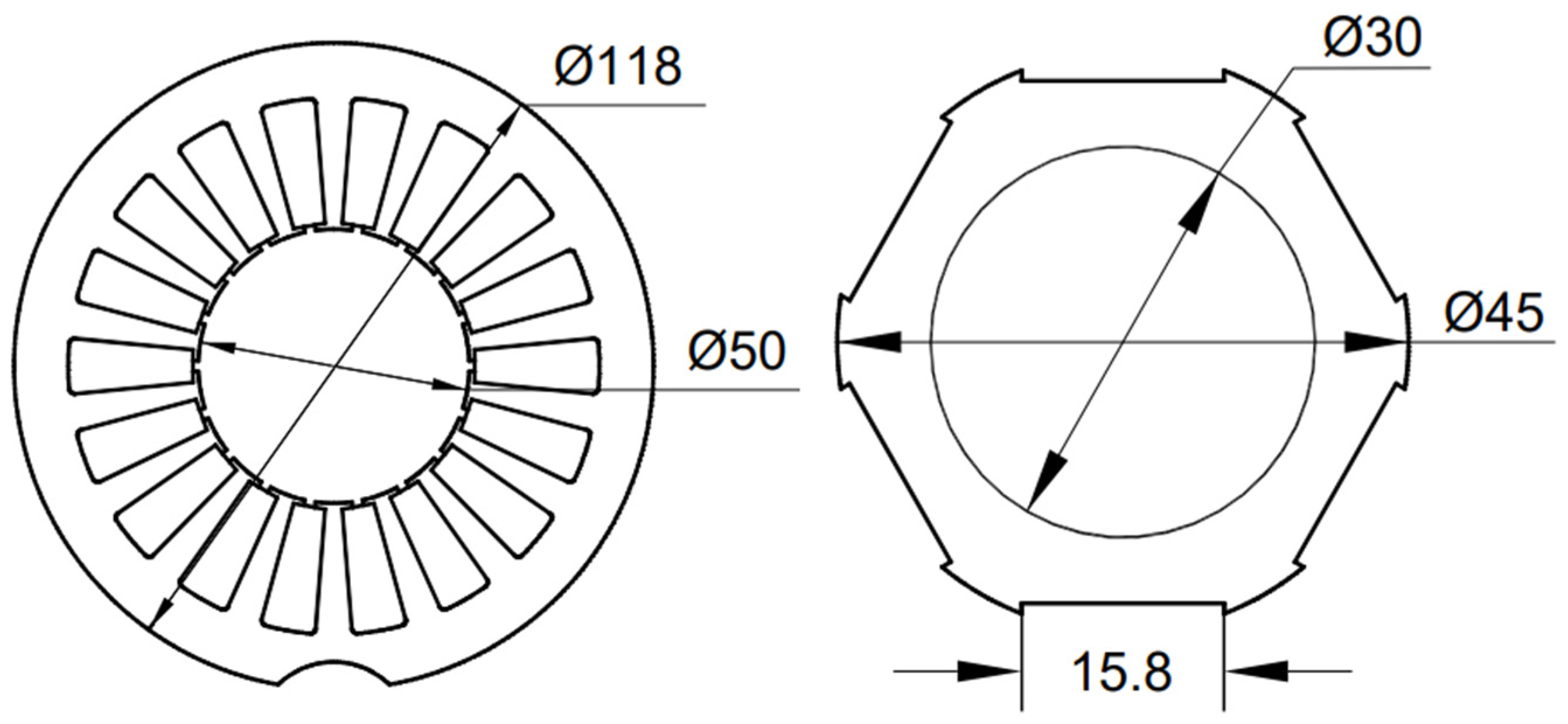
The main dimensions of the pre-sized three-phase, 18-slots surface PMSM are given in Figure 3.
The cross-section of the rotor with the permanent magnets with its main sizes can be seen in Figure 4.
In the 18 stator slots, a three-phase, double-layer, distributed winding was proposed to be placed. As can be seen in Figure 5, the pitch of the winding is three slots.
Upon these initial data, the model of the PMSM was built up in ANSYS Motor-CAD for evaluating the computed geometry and the selected winding, and for checking their correctness and feasibility.
3. The ANSYS Motor-CAD Model of the PMSM
By using the ANSYS Motor-CAD program, the building up of the surface-mounted PMSM model was very easy, as it needed only a few simple well-assisted steps to be performed.
To investigate the electromagnetic behavior of this PMSM, the electromagnetic module (named E-Magnetic) of the software was used. This enables the calculation of the electromagnetic performances by using both precise analytical and FEA methods [7,8].
The program offers to the designers eight predefined electromagnetic templates to be used for the study of the so-called Brushless Permanent-Magnet Motors (BPMs) category.
The first step in the model implementation was the definition of the stator and rotor iron cores. As can be seen in Figure 6, the sizes of the transversal and axial cross-sections of the PMSM had to be set from the Geometry menu of the program.
In the text boxes of the two panels, the main sizes of the iron cores (exterior and interior stator diameter, airgap length, shaft diameter, active length of the machine, and details about the stator teeth and slots) must be established.
Taking advantage of the possibility to export the cross-section of the iron cores in dxf-type CAD files, the resulting and the initial (obtained upon the pre-sizing of the machine) drawings were overlayed (see Figure 7). As can be seen, the designed and modeled structures are very close, so it can be stated that the iron core structure of the surface PMSM in the study was precisely modeled in ANSYS Motor-CAD.
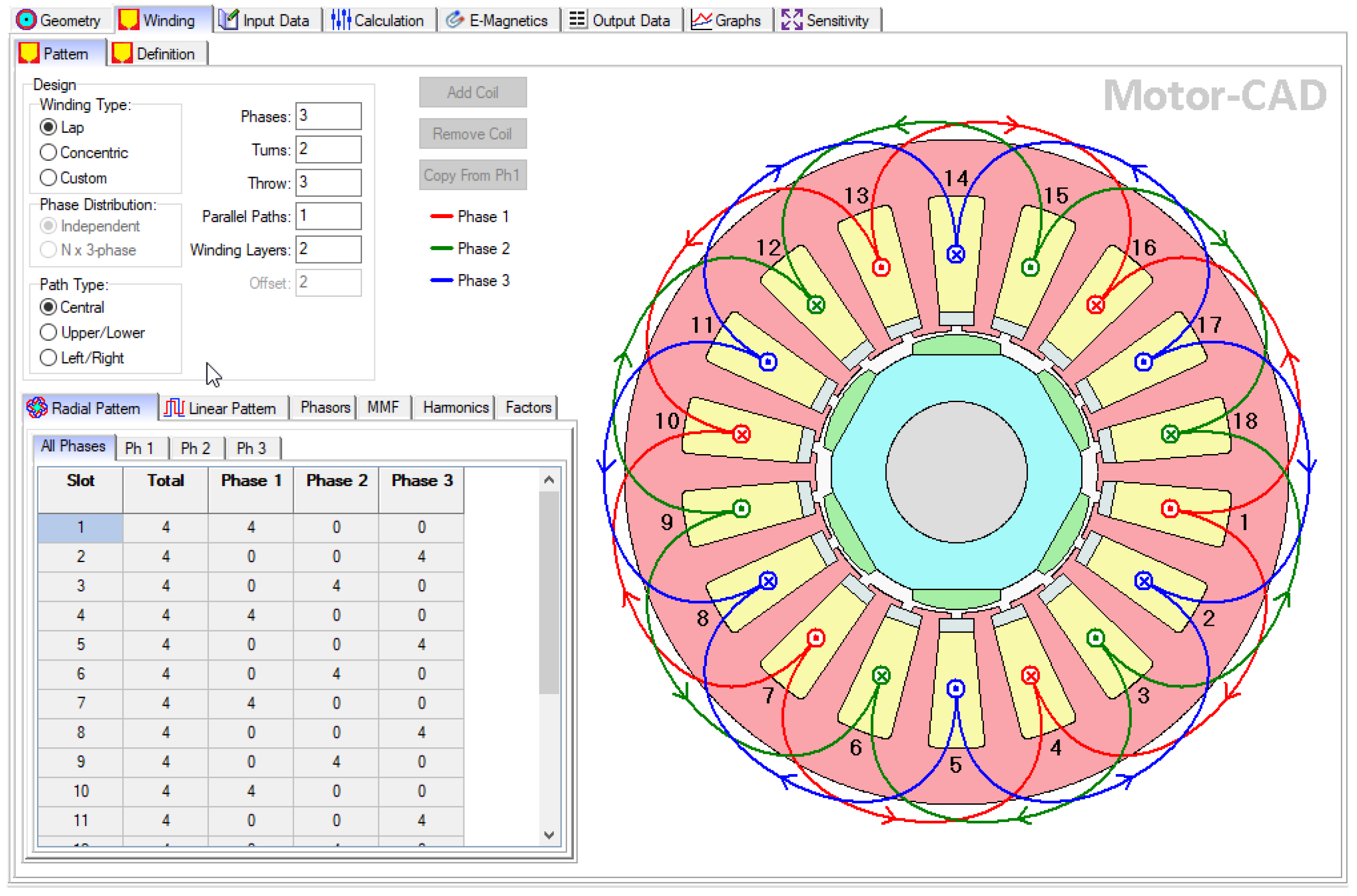
The winding diagram of the PMSM given in Figure 5 can also be very easily implemented in ANSYS Motor-CAD from its Winding menu. The lap type of the winding with a central path had to be selected. By specifying only five winding parameters (the numbers of the phases, turns, parallel paths, layers, and the throw length in slot steps), its model could be simply completed.
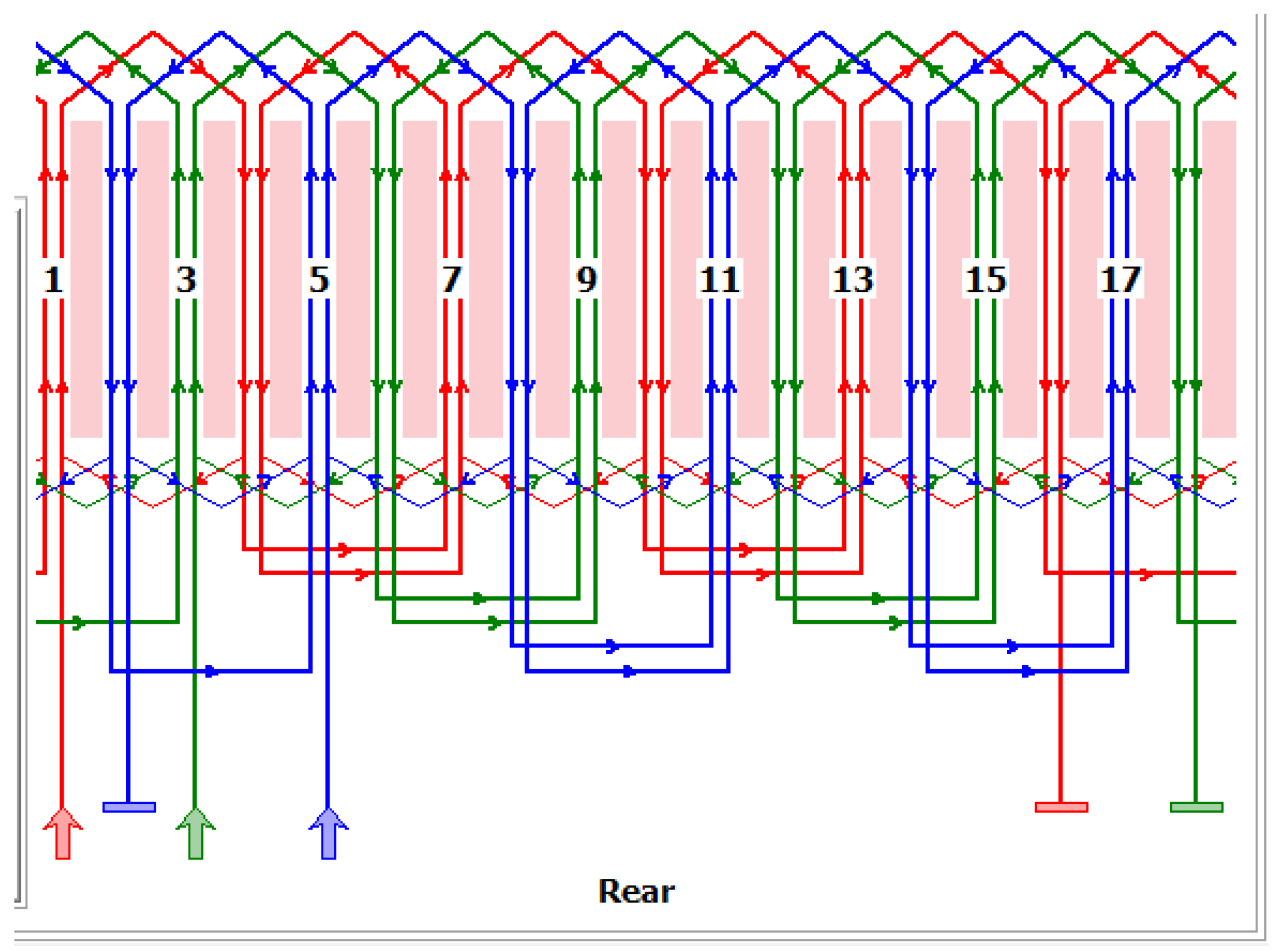
In the Pattern panel of the Winding menu, two types of winding diagrams automatically generated by the program can be visualized (see Figure 8 and Figure 9). By using these, the modeled winding diagram can be compared easily with that previously set up by the machine designer.
In the same panel, the phasor diagram, the MMF distribution in the airgap, and its harmonic content can be also visualized and checked.
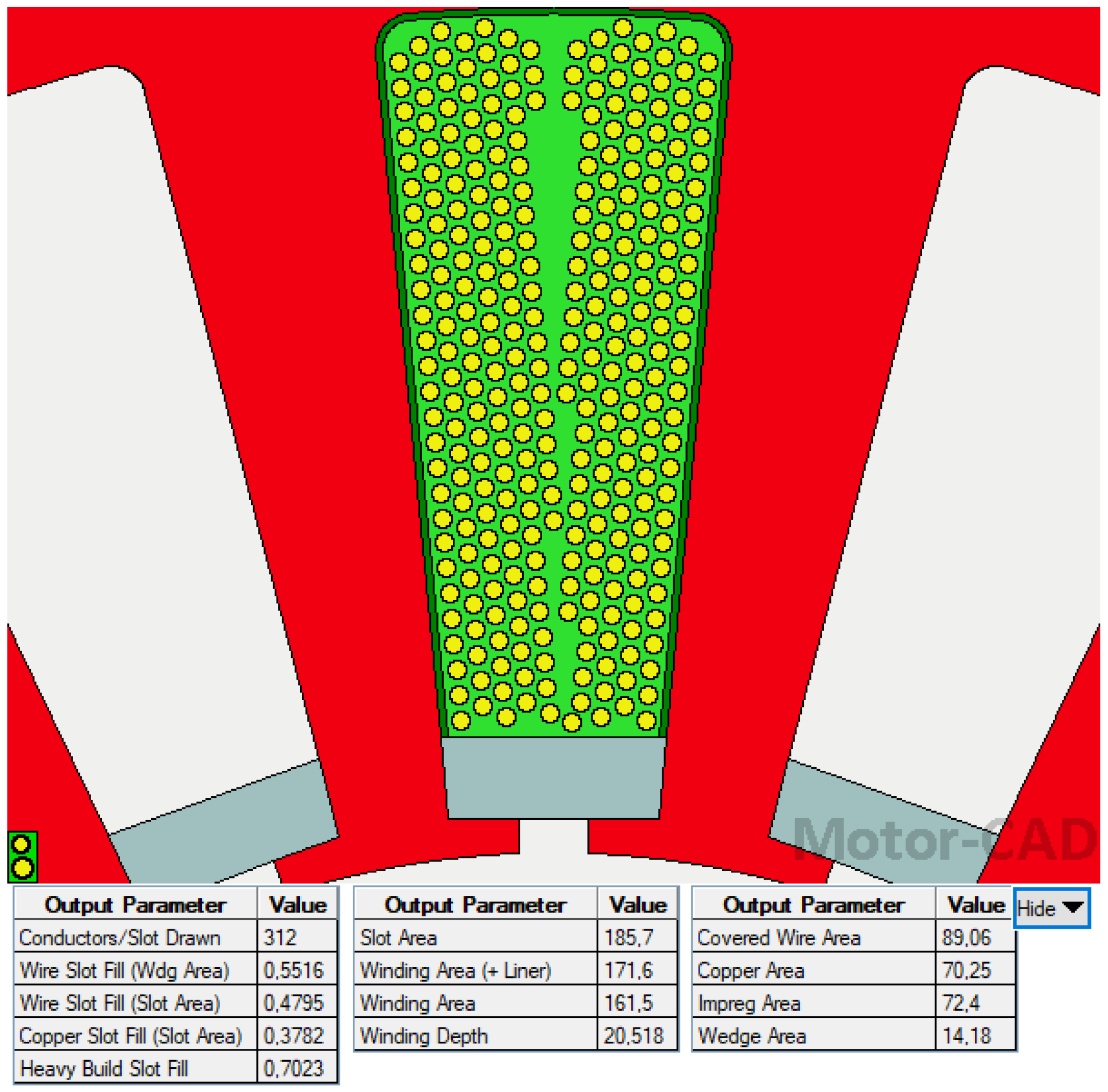
The Definition panel of the same Winding menu offers a specific and very useful feature of the ANSYS Motor-CAD software product. As can be seen in Figure 10, the filling of the slot is visualized upon the imposed number of turns, sizes of the conductors and insulators, etc. Additionally, a great variety of winding parameters are shown in this window, such as different areas, fill factors, etc.
The Conductors/Slot Drawn output parameter value should be colored in red to indicate an error if the designed winding does not fit into the slot area with the specified winding settings at the required fill factor.
In the next step of the modeling, the materials used in the construction of the surface PMSM had to be established. For this purpose, ANSYS Motor-CAD offers a huge database of the usual materials of electrical machines.
Fortunately, all the materials selected during the pre-sizing of the PMSM could be found in the provided database: M470-50A-type non-oriented 0.5 mm thick electric steel for the iron cores [66], pure copper for the windings, and the N35UH-type NdFeB permanent magnet [67], as can be seen in the material selection panel provided in Figure 11. In ANSYS Motor-CAD, there exists the possibility for the users to create their own databases for those materials which had not been included in the program database.
As can be seen in Figure 11, from this panel, information on the main characteristics of the used materials can be found. Important data regarding the masses of the PMSM components and the total machine mass can also be obtained from here.
With this last step, the model development in ANSYS Motor-CAD was practically finished. Next, the simulation conditions must be set in the Calculation menu of the program shown in Figure 12.
In this panel, the drive-related data must be set, such as the imposed speed of the machine, the RMS value of the supply currents, and the DC bus voltage. Additionally, here must be selected the type of drive, the connection of the stator windings, and the magnetization direction of the permanent magnets.
By using the selection possibilities in this panel, the users can choose which performance tests besides the ones mandatorily computed have to be performed by the program. ANSYS Motor-CAD can deliver the variations of the back EMF, cogging torque, and electromagnetic forces (both in open-circuit and on-load conditions). There is the possibility to obtain the torque versus speed (mechanical) characteristics of the analyzed electrical machines, too.
The simulations can be started from this panel by pressing the Solve E-Magnetic Model button.
4. Simulation Results
All the simulations to be next presented were performed at the rated conditions of the surface PMSM:
- 8000 r/min;
- 50 A RMS currents;
- 72 V DC bus voltage.
The ANSYS Motor-CAD software can perform simulations both on the entire machine structure or only on a part of it, considering the symmetry conditions. Despite that the FEA is perfectly performed at the default settings of the options concerning the solver, there are numerous possibilities of settings targeting the mesh fineness, the number of points in which the quantities of interest are computed, etc.
Upon the performed FEA, a great variety of results were obtained. Here only those of major interest for the study to be performed will be detailed.
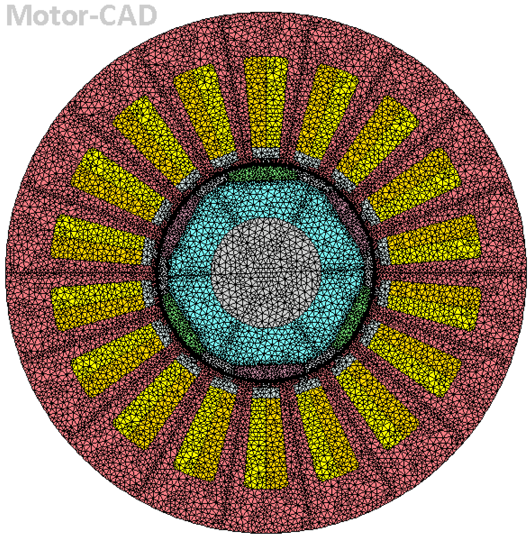
The basic results are gained upon the accomplished FEA of the modeled electrical machine and can be visualized in the E-Magnetics panel of the program. For example, the considered regions together with the automatically generated mesh can be pictured, as can be seen in Figure 13.
In the same panel, the color map of four different quantities (flux density, vector potential, current density, and eddy current density) together with the magnetic flux lines can be visualized. In Figure 14, the color maps of the flux density and the flux lines for three distinct positions during a complete 360-electrical-degree revolution of the rotor are provided.
The ANSYS Motor-CAD software can generate an animation by putting together slide-by-slide the results obtained at different rotor positions and can save this in an animated gif-type file.
A second possibility to analyze the obtained results is the evaluation of a great number of numeric results by accessing the Output Data panel. Here the following results categories (arranged in panes) can be evidenced:
- Drive: data concerning the back EMF, supply voltages and currents, d-q axes inductances and currents, machine constants, short circuit parameters, etc.;
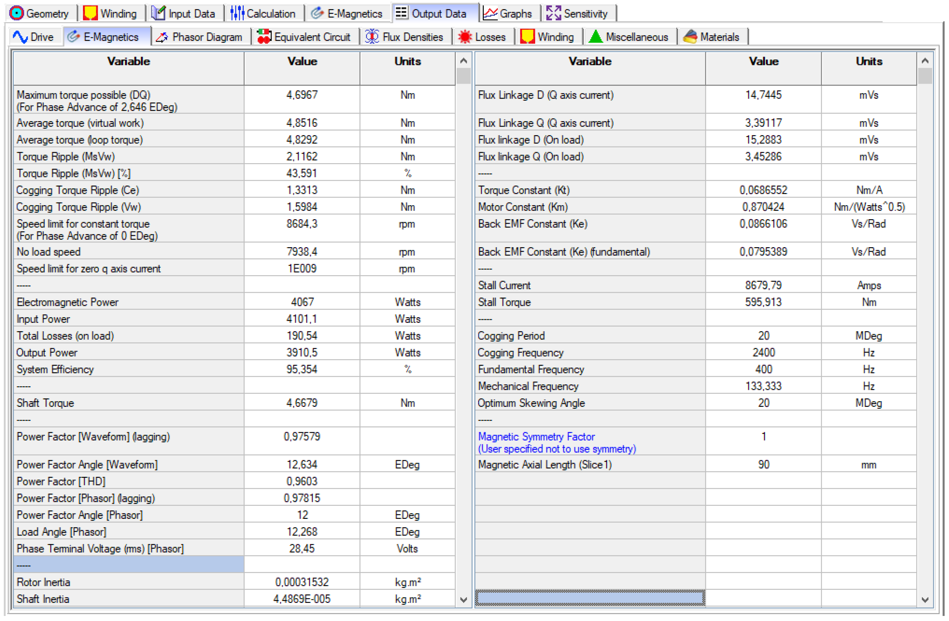
- E-Magnetics: the main parameters of the analyzed electrical machines are provided here (see Figure 15), such as the electromagnetic power, torque, cogging torque, power factor, system efficiency, load angle, cogging period, base frequency, etc.;
- Phasor Diagram;
- Equivalent Circuit: shows all the parameters of the most complete equivalent circuit;
- Flux densities in different critical parts of the machine;
- Losses in all the parts of the machine;
- Winding: provides the parameters and current densities of all the conductors, phase resistance, slot filling factors, copper volume, etc.;
- Miscellaneous: data about the FEA mesh generated by the program;
- Materials: the properties and masses of all the used materials.
As can be seen in Figure 15 and Table 1, the designed surface-mounted PMSM achieved all its imposed rated values (see Section 2.2).
The obtained power factor and efficiency of the PMSM are 0.975 and 95.36%, respectively (see Figure 15). Both are excellent values for such a machine having the given power. The 70.71 A phase current is under the 120 A maximum value of the power converter supplying the PMSM.
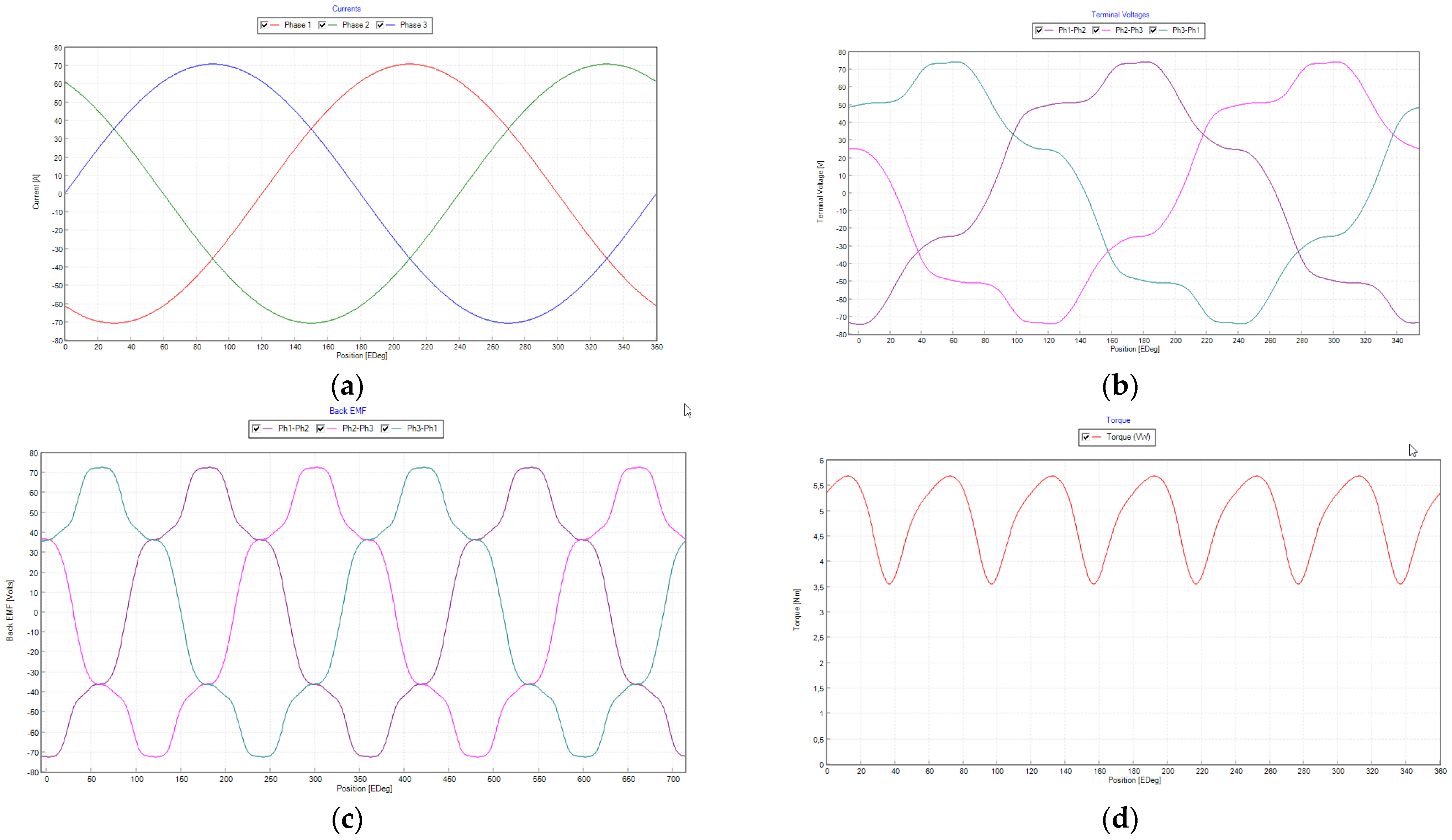
The third category of results is displayed graphically. A great variety of plots can be visualized from the Graphs panel of the ANSYS Motor-CAD software. The most eloquent ones are given in Figure 16 and Figure 17, where the phase currents, terminal voltages, back EMFs, electromagnetic torque, cogging torque (computed via two different methods), and airgap flux density are plotted versus the rotor position.
As the phase currents were imposed during the simulations, they have a perfect sinusoidal shape, and their peak value is 70.71 A, as it was forced (see this in Figure 12). The maximum values of the terminal voltages do not exceed the 72 V DC bus voltage. The back EMF produced in the generator regime is not perfectly sinusoidal, as could be expected. Its harmonic content can be extracted from the Harmonics window of the Graphs panel (see Figure 18), where the great 5th harmonic content can be easily observed. The generated torque has a significant ripple (equal to 43.5% upon the result given in Figure 15). The cogging torque is small upon the result obtained via both computation methods, based on the co-energy (CE) and virtual works (VWs).
There are some possibilities to manipulate the graphical results provided by the ANSYS Motor-CAD program from its Graph Editor. Various features of the plots can be set from here, and the final figure can be exported both in bitmap and metafile formats. The plotted numerical values arranged in tables can be visualized and exported in diverse formats for future processing in other programs.
The authors preferred to export the results obtained through simulations to MATLAB via the XML file format and to take advantage of the numerous graphical processing possibilities existing in this very popular computing platform [68].
5. Comparison of Four PMSM Types
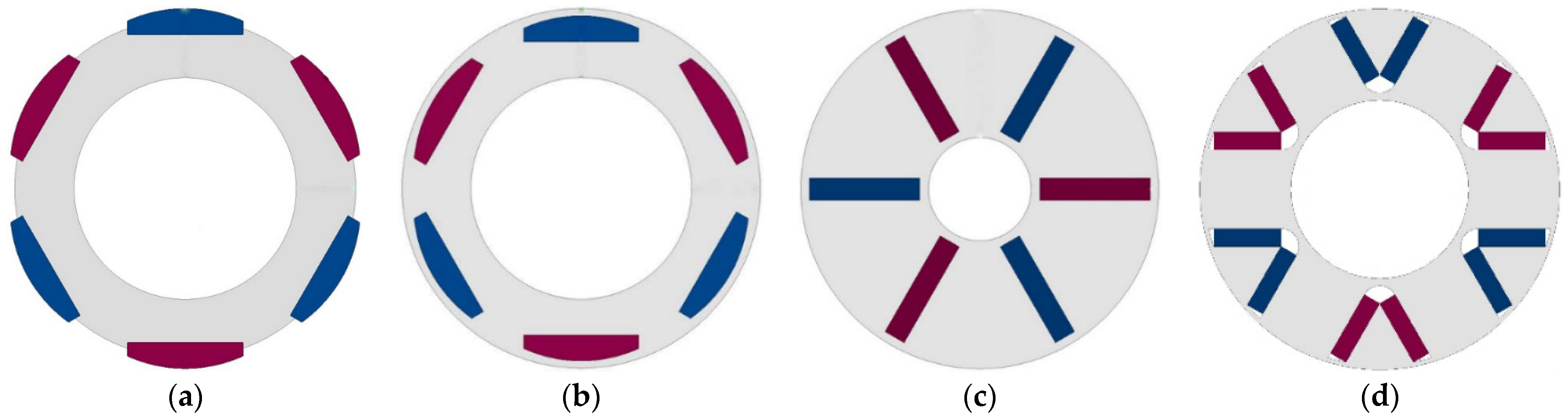
By using the advanced simulation features of the ANSYS Motor-CAD software, the comparison of four typical PMSM topologies (with surface mount, interior, spoke-type, and V-shaped permanent magnets) was performed. All of them have the same imposed rated values (given in Section 2.2), stator (concerning both their iron core and windings), and airgap. The rotors (shown in Figure 19) have the same permanent magnet volume.
5.1. Building up the Models of the Alternative PMSMs in ANSYS Motor-CAD
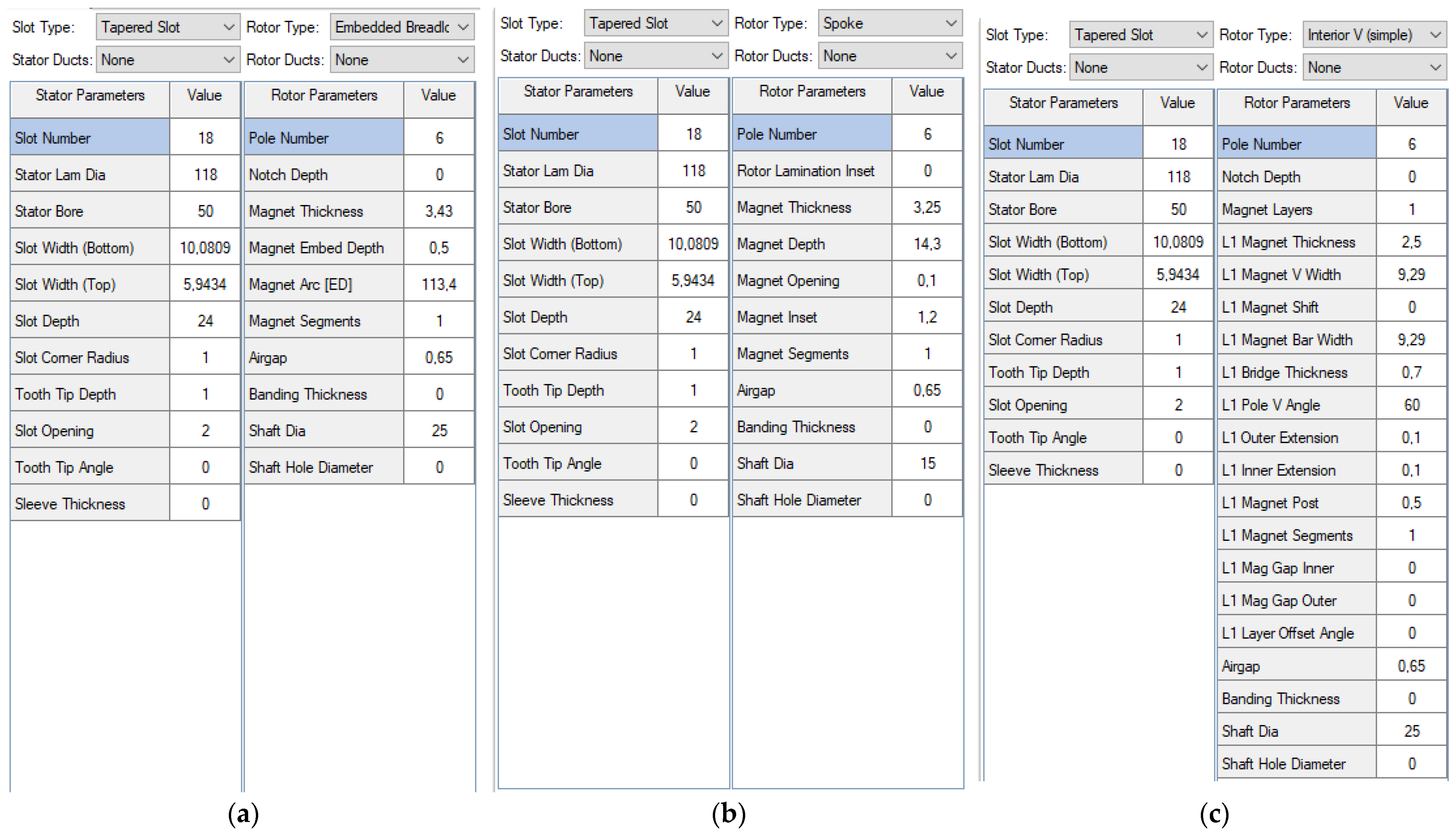
As in the ANSYS Motor-CAD software the size settings and the permanent magnet mass and volume computations can be performed very easily, the construction of the last three PMSM models was a very simple engineering task. The applied settings of the radial cross-section of the three PMSMs and the obtained structures are given in Figure 20 and Figure 21. The settings of the axial cross-sections of the four PMSMs are identical.
5.2. The Comparison of the Obtained Results
The simulation in ANSYS Motor-CAD of the four PMSMs was performed at identical settings (see them at the beginning of Section 4).
The extraction of the multitude of results after the performed simulations enabled the comparison of the four PMSM topologies from different points of view. First, the total masses and that of each main component can be compared. In Table 2 the masses of the main machine components (stator and rotor iron cores, permanent magnets, windings, and the shaft) are given. By adding these, the total masses of the PMSMs without the housings and machine auxiliaries can be obtained.
Since the stators of the four PMSMs are identical, and the permanent magnets are of the same volume, the rotor iron core mass makes the difference. In any case, the four total masses are very close, and the least is that of the surface-mounted PMSM.
In the above table and in all which follows, the best values are highlighted in green, while the worst are in red.
The assessment of the main output characteristics is essential in such a comparative study. Therefore, eight key features of the PMSMs in the study (output power, mean torque, torque ripple, peak-to-peak value of the cogging torque, efficiency, power factor, power density, and torque density) were included in Table 3.
As can be seen, the surface-mounted PMSM has the best characteristics in almost all the considered categories, while that having V-shape permanent magnets has the worst ones. It can be concluded that under the given conditions (identical stators, external and internal dimensions of the rotor iron cores, and permanent magnet masses), the topologies considered to be compared with the surface permanent magnet variant cannot reach the imposed rated speed (8,000 r/min), nor the rated output power (4 kW), nor the rated torque (4.77 N·m).
Next, the variation against the angular displacement of some basic characteristics of the four considered PMSM topologies will be studied.
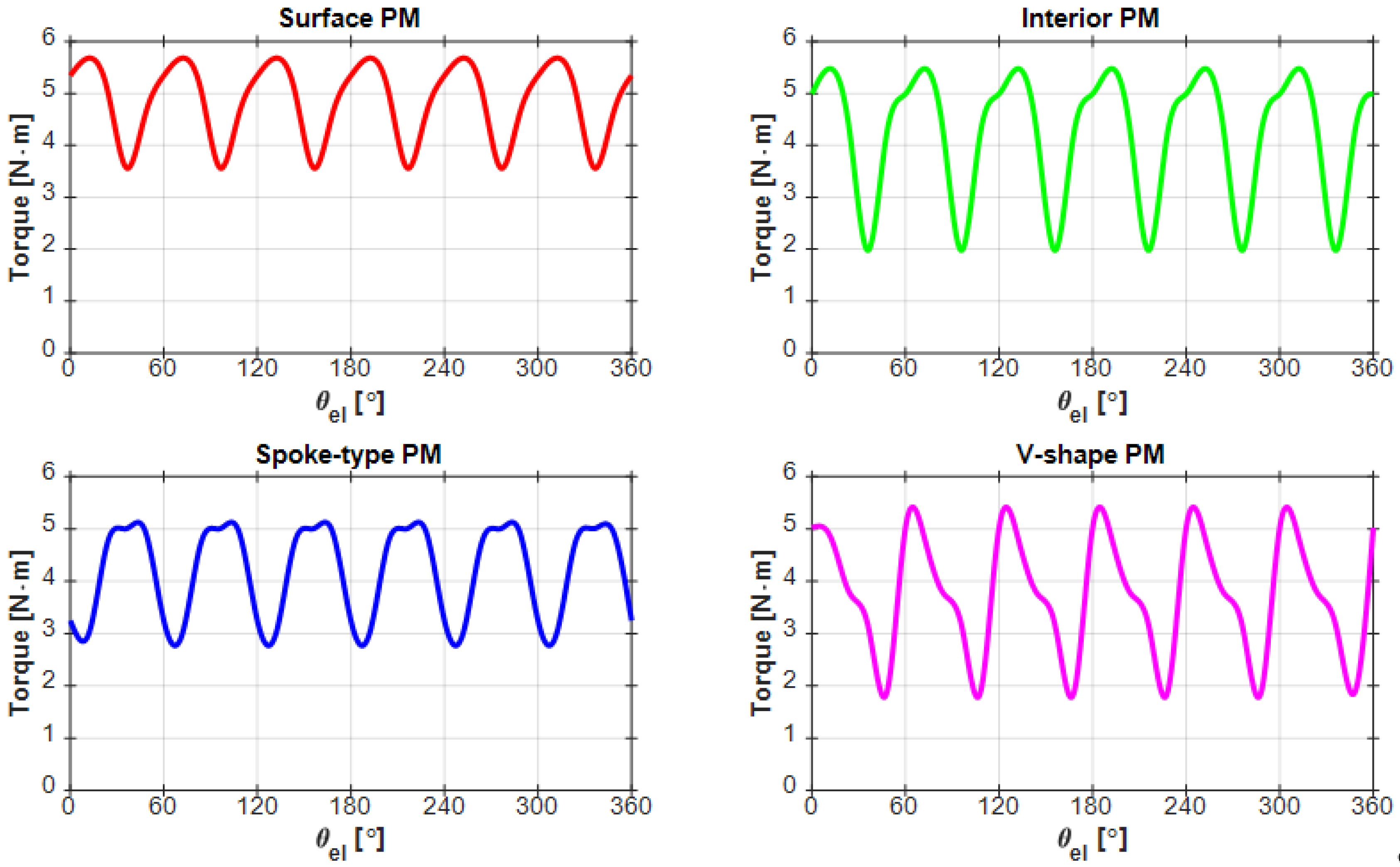
In Figure 22, the variation of the generated torque in all four cases is provided. For a better comparison of the PMSMs, the main torque features (the minimum, maximum, and mean values, and the torque ripple) are given in Table 4.
As is evident, the surface-mounted PMSM has the best torque development capability, due to the very close placement of the permanent magnets to the airgap of the machine. Meanwhile, the PMSM having V-shaped permanent magnets is the worst topology, also from this point of view.
In the case of all permanent magnet machines, the cogging torque is also a significant characteristic. Therefore, the variations of this physical quantity versus the angular displacement are shown in Figure 23.
The peak-to-peak values of the cogging torque of the four PMSMs are significant comparative issues (consider Table 3). As can be seen, the lowest cogging torque is developed by the spoke-type PMSM because in this topology the permanent magnets are deeply buried into the rotor iron core far from the rotor external surface and airgap. In the case of the V-type PMSM, the permanent magnets strongly concentrate the magnetic flux into the airgap, and consequentially also cause great cogging torques.
As is evidenced, again the surface-mounted PMSM has very good behavior based on this consideration, as well.
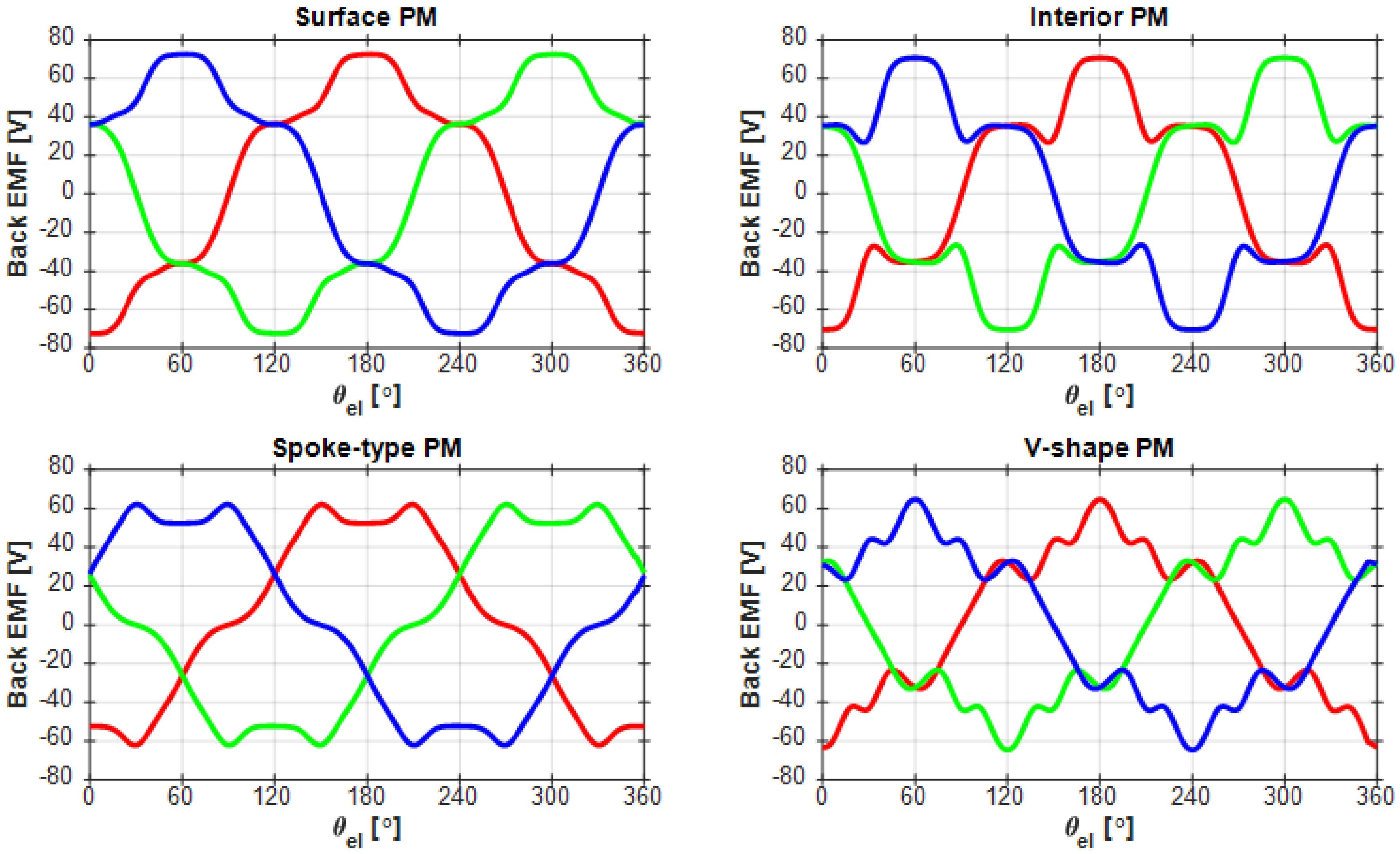
PMSMs are often used also in generator regime; therefore, the shapes of the produced EMF (given in Figure 24) are important issues in a such comparative study.
As could be expected and can be observed in Figure 24, the generated waveforms are far from the ideal sinusoidal shapes. Hence, their harmonic content is of major concern. These characteristics are again easy to extract from the results provided by the ANSYS Motor-CAD software. The results of the harmonic analysis were plotted by using the graphical potential of the MATLAB program as in the previous cases. The obtained results are given in Figure 25. In such cases, the total harmonic distortion (THD) of the waveforms is also of important relevance; therefore, their values were written on each plot from the figure.
The PMSM having spoke-type permanent magnets has the lowest harmonic content, but its THD value (0.2) is only a bit smaller than the THD obtained for the surface PMSM. These results were expectable, since it was proved in numerous papers that these two types of PMSM can generate the closest EMF waveform to the perfect sinusoidal ones [69].
6. Discussion
PMSMs are essential components of modern vehicles, being used both for traction purposes in electrical and hybrid cars and for actuating several car auxiliaries. Therefore, their design is an important issue and requires advanced software tools. Such a program, used by the authors in designing and analyzing PMSMs, is the ANSYS Motor-CAD software.
The simulations performed by using it enabled the authors to check the pre-sizing of the designed PMSM and to verify if all the imposed designed data were fulfilled. By applying the multiple PMSM structure templates offered by the ANSYS Motor-CAD program, it was possible to easily perform an in-detail comparison of four rotor structures for the identical stator of the PMSM and to define the best structure among them.
ANSYS Motor-CAD can also be useful in the future for improving the structure of the proposed PMSM by assisting in an effective optimization process.
7. Conclusions
By using the ANSYS Motor-CAD program in our concrete design work, we concluded that it was an effective tool in our hands. By using the built-in templates, the models of all the PMSMs taken into the study were easily achieved. Hence, the consistency of the pre-computed sizes of the machines was easily checked, and the CAD drawings of the main components could be exported for further studies or manufacturing.
The program has a huge database of materials, where the designers probably can find exactly the materials proposed during the pre-sizing of the machine. If not, they can create their own material databases even for very specific materials.
The designed winding diagram could be implemented in ANSYS Motor-CAD straightforwardly by setting only a few parameters. The program can display diverse diagrams of the modeled winding, also including the ideal displacement of the wires in the slots. This is one of the most spectacular features of the program since these computations are complicated due to the irregular shape of the slots. By the graphical illustration of the slot with the inserted wires and insulators, the users can easily decide on the correctness of the design and can have information about the actual filling factor of the winding.
The drive systems of the simulated electrical machines can be easily configured by some simple selections, avoiding the use of complicated-to-build external circuits with adequate commands.
By using both analytical computations and FEA, ANSYS Motor-CAD can deliver a great variety of results (both in graphical forms and as numerical values): the magnetic flux distribution in the machine, the flux densities in diverse areas, the masses of all distinct components, etc. Numerous output parameters (such as developed torque, cogging torque, power, efficiency, power factor, etc.) can be easily visualized and thus checked by the designing engineers.
If needed, the correction of the design can be made rapidly until all the required machine parameters are achieved.
During working with this software product, we also found some limitations of it. As it enables only a template-based model construction, electrical machines with special topologies (for example, those having modular construction or transverse flux machines), not included in the offered templates, cannot be studied. Despite the valuable simulation results obtained by using the default FEA settings, such a program should enable more possibilities for setting the mesh and the used solver.
In overall conclusion concerning the used software tool: ANSYS Motor-CAD was very worthwhile in our design work. By applying it, we could rapidly check our designs and perform needed changes to improve them.
It can be also stated that all the simulated results showed that the surface-mounted PMSM intended to drive the scroll-type compressor of a car HVAC system meets all the set design expectations. Moreover, the comparison study’s findings all underscored the advantages of this PMSM variant over the other three topologies that were taken into consideration.
Author Contributions
Conceptualization, L.S.; PMSM pre-sizing, I.V.; PMSM modeling, F.-A.C. All authors have read and agreed to the published version of the manuscript.
Funding
This research received no external funding.
Institutional Review Board Statement
Not applicable.
Informed Consent Statement
Not applicable.
Data Availability Statement
Not applicable.
Conflicts of Interest
The authors declare no conflict of interest.
References
- Rosu, M.; Zhou, P.; Lin, D.; Ionel, D.M.; Popescu, M.; Blaabjerg, F.; Rallabandi, V.; Staton, D. Multiphysics Simulation by Design for Electrical Machines, Power Electronics and Drives; John Wiley & Sons: Hoboken, NJ, USA, 2017. [Google Scholar]
- Lei, G.; Zhu, J.; Guo, Y.; Liu, C.; Ma, B. A review of design optimization methods for electrical machines. Energies 2017, 10, 1962. [Google Scholar] [CrossRef] [Green Version]
- Liu, X.; Lin, Q.; Fu, W. Optimal design of permanent magnet arrangement in synchronous motors. Energies 2017, 10, 1700. [Google Scholar] [CrossRef] [Green Version]
- Cepoi, R.D.; Jaşcău, F.F.; Szabó, L. Current trends in energy efficient electrical machines. J. Electr. Electron. Eng. 2017, 10, 13–18. [Google Scholar]
- Allam, Z.; Bibri, S.E.; Sharpe, S.A. The Rising Impacts of the COVID-19 Pandemic and the Russia–Ukraine War: Energy Transition, Climate Justice, Global Inequality, and Supply Chain Disruption. Resources 2022, 11, 99. [Google Scholar] [CrossRef]
- Bobba, S.; Carrara, S.; Huisman, J.; Mathieux, F.; Pavel, C. Critical Raw Materials for Strategic Technologies and Sectors in the EU. A Foresight Study; European Union: Brussels, Belgium, 2020. [Google Scholar]
- Hameyer, K.; Belmans, R. Numerical Modelling and Design of Electrical Machines and Devices; WIT Press: Ashurst Lodge, UK, 1999. [Google Scholar]
- Salon, S.J. Finite Element Analysis of Electrical Machines; Kluwer Academic Publishers: Boston, MA, USA, 1995. [Google Scholar]
- JMAG-Designer. User’s Manual Solver, 19th ed.; JSOL Corporation: Tokyo, Japan, 2020. [Google Scholar]
- Jun, S.-B.; Kim, C.-H.; Cha, J.; Lee, J.H.; Kim, Y.-J.; Jung, S.-Y. A novel method for establishing an efficiency map of IPMSMs for EV propulsion based on the finite-element method and a neural network. Electronics 2021, 10, 1049. [Google Scholar] [CrossRef]
- Gecer, B.; Tosun, O.; Apaydin, H.; Serteller, N.F.O. Comparative Analysis of SRM, BLDC and Induction Motor Using ANSYS/Maxwell. In Proceedings of the International Conference on Electrical, Computer, Communications and Mechatronics Engineering (ICECCME ‘2021), Mauritius, 7–8 October 2021. [Google Scholar] [CrossRef]
- Aishwarya, M.; Brisilla, R. Design of Energy-Efficient Induction motor using ANSYS software. Results Eng. 2022, 16, 100616. [Google Scholar] [CrossRef]
- Varvolik, V.; Prystupa, D.; Buticchi, G.; Peresada, S.; Galea, M.; Bozhko, S. Co-simulation analysis for performance prediction of synchronous reluctance drives. Electronics 2021, 10, 2154. [Google Scholar] [CrossRef]
- Dobzhanskyi, O.; Grebenikov, V.; Gouws, R.; Gamaliia, R.; Hossain, E. Comparative thermal and demagnetization analysis of the PM machines with neodymium and ferrite magnets. Energies 2022, 15, 4484. [Google Scholar] [CrossRef]
- Falkowski, K.; Kurnyta-Mazurek, P.; Szolc, T.; Henzel, M. Radial magnetic bearings for rotor–shaft support in electric jet engine. Energies 2022, 15, 3339. [Google Scholar] [CrossRef]
- Lukočius, R.; Vilkauskas, A.; Marčiulionis, P.; Grigaliūnas, V.; Nakutis, Ž.; Deltuva, R. An analysis of axial magnetic coupling force and torque dependencies on its structure parameters using a 3D FEM. Appl. Sci. 2022, 12, 6546. [Google Scholar] [CrossRef]
- Uberti, F.; Frosini, L.; Szabó, L. A new design procedure for rotor laminations of synchronous reluctance machines with fluid shaped barriers. Electronics 2022, 11, 134. [Google Scholar] [CrossRef]
- Ullah, A.; Reja, M.I.; Mirza, F.; Ahmed, H. Design of permanent magnet synchronous machines of direct-driven generator with Emetor and FLUX 2D. In Proceedings of the IEEE Business, Engineering & Industrial Applications Colloquium (BEIAC ‘2012), Kuala Lumpur, Malaysia, 7–8 April 2012; pp. 74–79. [Google Scholar] [CrossRef]
- Someşan, L.; Pădurariu, E.; Viorel, I.A.; Szabó, L. Design of a permanent magnet flux-switching machine. In Proceedings of the 9th International Conference ELEKTRO ‘2012, Žilina–Rajecké Teplice, Slovakia, 21–22 May 2012; pp. 256–259. [Google Scholar] [CrossRef]
- Hernández, J.A.D.; Carralero, N.D.; Vázquez, E.G. A 3-D Simulation of a Single-Sided Linear Induction Motor with Transverse and Longitudinal Magnetic Flux. Appl. Sci. 2020, 10, 7004. [Google Scholar] [CrossRef]
- Islam, M.S.; Agoro, S.; Chattopadhyay, R.; Husain, I. Heavy rare earth free high power density traction machine for electric vehicles. In Proceedings of the IEEE International Electric Machines & Drives Conference (IEMDC ‘2021), Hartford, CT, USA, 17–20 May 2021. [Google Scholar] [CrossRef]
- Paiva, L.T.; Fontes, F.A.C.C. Optimal control algorithms with adaptive time-mesh refinement for kite power systems. Energies 2018, 11, 475. [Google Scholar] [CrossRef] [Green Version]
- Lo, S. Finite element mesh generation and adaptive meshing. Prog. Struct. Eng. Mater. 2002, 4, 381–399. [Google Scholar] [CrossRef]
- Okereke, M.; Keates, S. Finite Element Applications. A Practical Guide to the FEM Process; Springer International Publishing AG: Cham, Switzerland, 2018. [Google Scholar]
- Li, H. The finite element method. In Graded Finite Element Methods for Elliptic Problems in Nonsmooth Domains. Surveys and Tutorials in the Applied Mathematical Sciences; Springer: Cham, Switzerland, 2022; Volume 10, pp. 1–12. [Google Scholar]
- Mersha, T.K.; Du, C. Co-simulation and modeling of PMSM based on ANSYS software and Simulink for EVs. World Electr. Veh. J. 2021, 13, 4. [Google Scholar] [CrossRef]
- Filipenko, M.; Biser, S.; Boll, M.; Corduan, M.; Noe, M.; Rostek, P. Comparative analysis and optimization of technical and weight parameters of turbo-electric propulsion systems. Aerospace 2020, 7, 107. [Google Scholar] [CrossRef]
- Ibrahim, I.; Silva, R.; Lowther, D.A. Application of surrogate models to the multiphysics sizing of permanent magnet synchronous motors. IEEE Trans. Magn. 2022, 58, 7401604. [Google Scholar] [CrossRef]
- Boldea, I.; Tutelea, L.N. Electric Machines: Steady State, Transients, and Design with MATLAB®; CRC Press: Boca Raton, FL, USA, 2010. [Google Scholar]
- Motor-CAD Software. Available online: https://www.motor-design.com/motor-cad/ (accessed on 15 November 2022).
- Staton, D.; Goss, J. Open Source Electric Motor Models for Commercial EV & Hybrid Traction Motors; Motor Design Ltd.: Ellesmere, UK, 2017. [Google Scholar]
- Qi, J.; Hua, W.; Zhang, H. Thermal analysis of modular-spoke-type permanent-magnet machines based on thermal network and FEA method. IEEE Trans. Magn. 2019, 55, 8104105. [Google Scholar] [CrossRef]
- Staton, D. Servo motor size reduction—Need for thermal CAD. In Proceedings of the Drives & Controls Conference (ExCeL‘2001), London, UK, 13–15 March 2001; pp. 13–15. [Google Scholar]
- Staton, D.; Hawkins, D.; Popescu, M. Motor-CAD software for thermal analysis of electrical motors–Links to electromagnetic and drive simulation models. In Proceedings of the Coil Winding, Insulation & Electrical Manufacturing Exhibitions Conference (CWIEME ‘2010), Berlin, Germany, 5 January 2010. [Google Scholar]
- Jie, D. Thermal performance analysis of motor based on Motor-CAD. In Proceedings of the 3rd International Conference on Advances in Materials, Machinery, Electronics, AMME, 2019, Wuhan, China, 19–20 January 2019; AIP Conference Proceedings. Volume 2073, p. 5090703. [Google Scholar]
- Deaconu, D.I.; Ghiţă, C.; Chirilă, A.I.; Năvrăpescu, V.; Popescu, M. Thermal study of induction machine using Motor-CAD. In Proceedings of the 3rd International Symposium on Electrical and Electronics Engineering (ISEEE ‘2010), Galați, Romania, 16–18 September 2010; pp. 23–27. [Google Scholar] [CrossRef]
- Staton, D.; Boglietti, A.; Cavagnino, A. Solving the more difficult aspects of electric motor thermal analysis. In Proceedings of the IEEE International Electric Machines and Drives Conference (IEMDC ‘03), Madison, WI, USA, 1–4 June 2003; pp. 747–755. [Google Scholar] [CrossRef]
- Bramerdorfer, G.; Tapia, J.A.; Pyrhönen, J.J.; Cavagnino, A. Modern electrical machine design optimization: Techniques, trends, and best practices. IEEE Trans. Ind. Electron. 2018, 65, 7672–7684. [Google Scholar] [CrossRef]
- Boglietti, A.; Cavagnino, A.; Staton, D.; Shanel, M.; Mueller, M.; Mejuto, C. Evolution and modern approaches for thermal analysis of electrical machines. IEEE Trans. Ind. Electron. 2009, 56, 871–882. [Google Scholar] [CrossRef] [Green Version]
- Rivière, N.; Villani, M.; Popescu, M. Optimisation of a high speed copper rotor induction motor for a traction application. In Proceedings of the 45th Annual Conference of the IEEE Industrial Electronics Society (IECON ‘2019), Lisbon, Portugal, 14–17 October 2019; pp. 2720–2725. [Google Scholar] [CrossRef]
- Salah, A.A.; Guo, Y.; Dorrell, D.G. Predicting the behavior of induction machine using motor-CAD and MATLAB packages. In Proceedings of the 12th International Conference on Compatibility, Power Electronics and Power Engineering (CPE-POWERENG ‘2018), Doha, Qatar, 10–12 April 2018. [Google Scholar] [CrossRef]
- Lyshevski, S.E. Electromechanical Systems, Electric Machines, and Applied Mechatronics; CRC Press: Boca Raton, FL, USA, 2018. [Google Scholar]
- Matković, K.; Splechtna, R.; Gračanin, D.; Todorović, G.; Goja, S.; Bedić, B.; Hauser, H. Getting insight into noise, vibration, and harshness simulation data. In Proceedings of the Winter Simulation Conference (WSC ‘2021), Phoenix, AZ, USA, 18–24 July 2021. [Google Scholar] [CrossRef]
- Daly, S. Automotive Air Conditioning and Climate Control Systems; Elsevier: Amsterdam, The Netherlands, 2006. [Google Scholar]
- Wagner, J.; VanGelder, K. Automotive Heating, Ventilation, and Air Conditioning; Jones & Bartlett Learning: Burlington, VT, USA, 2019. [Google Scholar]
- Li, W.; He, Y. Parameterization and performance of permanent magnet synchronous motor for vehicle based on Motor-CAD and OptiSLang. Wirel. Commun. Mob. Comput. 2022, 2022, 1–12. [Google Scholar] [CrossRef]
- Li, X.X.; Liu, Z.S. Optimization design and analysis of permanent magnet synchronous generator based on Motor-CAD. J. Phys. Conf. Ser. 2022, 2345, 012009. [Google Scholar] [CrossRef]
- Chin, Y.; Soulard, J. A permanent magnet synchronous motor for traction applications of electric vehicles. In Proceedings of the International Electric Machines and Drives Conference (IEMDC ‘2003), Madison, WI, USA, 1–4 June 2003; pp. 1035–1041. [Google Scholar] [CrossRef]
- Hirano, T.; Matsumura, N.; Takeda, K. Development of high efficiency scroll compressors, for air conditioners. In Proceedings of the 1988 International Compressor Engineering Conference, West Lafayette, IN, USA, 18–21 July 1988; p. 603. [Google Scholar]
- Aurich, J.; Baumgart, R. Comparison and evaluation of different A/C compressor concepts for electric vehicles. In Proceedings of the 24th International Compressor Engineering Conference, West Lafayette, IN, USA, 9–12 July 2018; p. 2608. [Google Scholar]
- Cardone, M.; Gargiulo, B. Numerical simulation and experimental validation of an oil free scroll compressor. Energies 2020, 13, 5863. [Google Scholar] [CrossRef]
- Everything You Need to Know About Scroll Pumps. Available online: https://www.vacuumscienceworld.com/blog/everything-you-need-to-know-about-scroll-pumps (accessed on 1 December 2022).
- Cosman, S.-I.; Văscan, I.; Bilațiu, C.-A.; Tintelecan, A.; Marțiș, C.S.; Zorlescu, B. Design and analysis of a heating, ventilation and air conditioning system for electric vehicles. In Proceedings of the International Symposium on Power Electronics, Electrical Drives, Automation and Motion (SPEEDAM ‘2020), Sorrento, Italy, 24–26 June 2020; pp. 305–310. [Google Scholar] [CrossRef]
- Fodorean, D.; Popa, D.; Minciunescu, P.; Irimia, C.; Szabó, L. Study of a high-speed motorization for electric vehicle based on PMSM, IM and VRSM. In Proceedings of the 21st International Conference on Electrical Machines (ICEM ‘2014), Berlin, Germany, 2–5 September 2014; pp. 2577–2582. [Google Scholar] [CrossRef]
- Goli, C.S.; Manjrekar, M.; Essakiappan, S.; Sahu, P.; Shah, N. Landscaping and review of traction motors for electric vehicle applications. In Proceedings of the Transportation Electrification Conference & Expo (ITEC ‘2021), Chicago, IL, USA, 21–25 June 2021; pp. 162–168. [Google Scholar]
- Adamas Intelligence. Global PMSM Market Share Continues to Rise Despite Soaring Rare Earth Prices; Adamas Intelligence: Toronto, Canada, 2021. [Google Scholar]
- Naphade, A. Permanent Magnet Synchronous Motor (PMSM) Market Report, History and Forecast Breakdown Data by Types and Application till 2028; Skyline Market Research LLP: Kalyani Nagar, India, 2022. [Google Scholar]
- Văscan, I.; Szabó, L. Improvement trends in the development of permanent magnet synchronous machines for automotive applications. In Proceedings of the 23rd International Carpathian Control Conference (ICCC ‘2022), Sinaia, Romania, 29 May–1 June 2022; pp. 398–403. [Google Scholar] [CrossRef]
- Pyrhonen, J.; Jokinen, T.; Hrabovcova, V. Design of Rotating Electrical Machines; John Wiley & Sons: Chichester, UK, 2013. [Google Scholar]
- Candelo-Zuluaga, C.; Espinosa, A.G.; Riba, J.-R.; Blanch, P.T. PMSM design for achieving a target torque-speed-efficiency map. IEEE Trans. Veh. Technol. 2020, 69, 14448–14457. [Google Scholar] [CrossRef]
- Verbelen, F.; Abdallh, A.; Vansompel, H.; Stockman, K.; Sergeant, P. Sizing methodology based on scaling laws for a permanent magnet electrical variable transmission. IEEE Trans. Ind. Electron. 2019, 67, 1739–1749. [Google Scholar] [CrossRef] [Green Version]
- Rechkemmer, S.K.; Izumi, R.; Zhang, W.; Sawodny, O. Estimation of permanent magnet synchronous machine performance for pre-design using a reluctance network. IFAC-Pap. 2018, 51, 75–80. [Google Scholar] [CrossRef]
- Shen, Q.; Zhou, Z.; Li, S.; Liao, X.; Wang, T.; He, X.; Zhang, J. Design and analysis of the high-speed permanent magnet motors: A review on the state of the art. Machines 2022, 10, 549. [Google Scholar] [CrossRef]
- Lipo, T.A. Introduction to AC Machine Design; John Wiley & Sons: Hoboken, NJ, USA, 2017. [Google Scholar]
- Kou, S.; Kou, Z.; Wu, J.; Wang, Y. Modeling and simulation of a novel low-speed high-torque permanent magnet synchronous motor with asymmetric stator slots. Machines 2022, 10, 1143. [Google Scholar] [CrossRef]
- Electrical Steel Sheets—JFE G-CORE, JFE N-CORE; JFE Steel Corporation: Tokyo, Japan, 2016.
- N35UH Sintered Neodymium-Iron-Boron Magnets; Arnold Magnetic Technologies Corp.: Rochester, NY, USA, 2014.
- Majumdar, N.; Banerjee, S. MATLAB Graphics and Data Visualization Cookbook; Packt Publishing: Birmingham, UK, 2012. [Google Scholar]
- Chen, A.; Nilssen, R.; Nysveen, A. Harmonic analysis and comparison of the back EMFs of four permanent magnet machine with different winding arrangements. In Proceedings of the 2008 International Conference on Electrical Machines and Systems (ICEMS ‘2008), Wuhan, China, 17–20 October 2008; pp. 3043–3048. [Google Scholar]
Figure 1.
The scroll-type compressor. (a) The two co-wound spiral-shaped scrolls; (b) internal view of the compressor. Courtesy of the Vacuum Science World [52].
Figure 1.
The scroll-type compressor. (a) The two co-wound spiral-shaped scrolls; (b) internal view of the compressor. Courtesy of the Vacuum Science World [52].

Figure 2.
The mechanical characteristic of the PMSM to be designed.

Figure 3.
The main sizes (in mm) of the stator and rotor iron core laminations.

Figure 4.
Cross-section of the rotor with the permanent magnets on it (all sizes are in mm).

Figure 5.
The winding diagram of the PMSM.

Figure 6.
The panels of the ANSYS Motor-CAD program for setting the geometrical data of the stator and rotor iron cores. (a) Radial view; (b) axial view.
Figure 6.
The panels of the ANSYS Motor-CAD program for setting the geometrical data of the stator and rotor iron cores. (a) Radial view; (b) axial view.

Figure 7.
The overlayed drawings of the designed (black lines) and modelled (lines drawn in red) iron cores of the PMSM (showing only half of the motor cross-section).
Figure 7.
The overlayed drawings of the designed (black lines) and modelled (lines drawn in red) iron cores of the PMSM (showing only half of the motor cross-section).

Figure 8.
The radial pattern of the PMSM winding diagrams implemented in ANSYS Motor-CAD.

Figure 9.
The linear pattern of the PMSM winding diagram as provided by the ANSYS Motor-CAD software.
Figure 9.
The linear pattern of the PMSM winding diagram as provided by the ANSYS Motor-CAD software.

Figure 10.
The Winding-Definition panel showing the way the conductors of the windings are placed in the stator slots and listing numerous parameters of the winding.
Figure 10.
The Winding-Definition panel showing the way the conductors of the windings are placed in the stator slots and listing numerous parameters of the winding.

Figure 11.
The Materials panel of the Input Data menu used for selecting the materials for the different components of the modeled PMSM.
Figure 11.
The Materials panel of the Input Data menu used for selecting the materials for the different components of the modeled PMSM.

Figure 12.
The Calculation menu where all the simulation conditions must be established.

Figure 13.
The different regions of the analyzed PMSM and the mesh generated by the ANSYS Motor-CAD program.
Figure 13.
The different regions of the analyzed PMSM and the mesh generated by the ANSYS Motor-CAD program.

Figure 14.
The color map of the magnetic flux density and the plotted flux lines at three different mechanical angle displacements of the rotor. (a) 0°; (b) 10°; (c) 20°.
Figure 14.
The color map of the magnetic flux density and the plotted flux lines at three different mechanical angle displacements of the rotor. (a) 0°; (b) 10°; (c) 20°.

Figure 15.
The numerical simulation results provided in the E-Magnetics pane of the ANSYS Motor-CAD software.
Figure 15.
The numerical simulation results provided in the E-Magnetics pane of the ANSYS Motor-CAD software.

Figure 16.
The variation against rotor angular position of the quantities of most interest. (a) Phase currents; (b) terminal voltages; (c) back EMF; (d) developed torque.
Figure 16.
The variation against rotor angular position of the quantities of most interest. (a) Phase currents; (b) terminal voltages; (c) back EMF; (d) developed torque.

Figure 17.
The waveforms of the quantities of most interest. (a) Cogging torque; (b) airgap flux density.
Figure 17.
The waveforms of the quantities of most interest. (a) Cogging torque; (b) airgap flux density.

Figure 18.
The harmonic content of the back EMF waveform obtained by using ANSYS Motor-CAD software.
Figure 18.
The harmonic content of the back EMF waveform obtained by using ANSYS Motor-CAD software.

Figure 19.
The four considered PMSM rotor topologies with different placements of the permanent magnets. (a) Surface mount; (b) interior; (c) spoke-type; (d) V-shaped.
Figure 19.
The four considered PMSM rotor topologies with different placements of the permanent magnets. (a) Surface mount; (b) interior; (c) spoke-type; (d) V-shaped.

Figure 20.
The settings of the radial cross-section of the considered PMSMs with the different alternative permanent magnet arrangements. (a) Interior; (b) spoke-type; (c) V-shaped.
Figure 20.
The settings of the radial cross-section of the considered PMSMs with the different alternative permanent magnet arrangements. (a) Interior; (b) spoke-type; (c) V-shaped.

Figure 21.
The structures generated by ANSYS Motor-CAD of the alternative considered PMSMs having diverse permanent magnet placements. (a) Interior; (b) spoke-type; (c) V-shaped.
Figure 21.
The structures generated by ANSYS Motor-CAD of the alternative considered PMSMs having diverse permanent magnet placements. (a) Interior; (b) spoke-type; (c) V-shaped.

Figure 22.
The torque versus angular displacement plots for the four PMSMs.

Figure 23.
The cogging torque plotted against the angular displacement for the four PMSMs.

Figure 24.
The back EMF generated in the case of the four PMSMs.

Figure 25.
The harmonic contents of the back EMF waveforms given in Figure 24.
Figure 25.
The harmonic contents of the back EMF waveforms given in Figure 24.


Table 1.
The imposed rated values of the PMSM and the obtained ones via simulations.
| Item | Rated Value | Resulted from Simulation |
|---|---|---|
| DC bus voltage | 72 V | 72 V (imposed) |
| Rated power | 4 kW | 4.0596 kW |
| Rated speed | 8000 r/min | 8000 r/min (imposed) |
| Rated average torque | 4.77 N·m | 4.82 N·m |
Table 2.
The masses of the four PMSM components and their total masses.
| Mass [kg] | Permanent Magnet Topology | |||
|---|---|---|---|---|
| Surface | Interior | Spoke-Type | V-Shape | |
| Stator core | 3.736 | 3.736 | 3.736 | 3.736 |
| Rotor core | 0.6537 | 0.7301 | 0.9116 | 0.7274 |
| Permanent magnets | 0.1881 | 0.1881 | 0.1882 | 0.1881 |
| Windings | 1.846 | 1.846 | 1.846 | 1.846 |
| Shaft | 0.5743 | 0.5743 | 0.5743 | 0.5743 |
| Total mass | 6.9981 | 7.0745 | 7.2561 | 7.0718 |
Table 3.
The main characteristics of the four PMSMs.
| Characteristics | Permanent Magnet Topology | |||
|---|---|---|---|---|
| Surface | Interior | Spoke-Type | V-Shape | |
| Output power [W] | 4067 | 3516.6 | 3520.9 | 3129.4 |
| Mean torque [N·m] | 4.851 | 4.192 | 4.193 | 3.731 |
| Torque ripple [%] | 43.87 | 83.5 | 56.16 | 97.78 |
| Cogging torque peak-to-peak [N·m] | 1.58 | 2.56 | 1.28 | 4.16 |
| Efficiency [%] | 95.354 | 92.912 | 94.081 | 92.289 |
| Power factor [–] | 0.975 | 0.851 | 0.89 | 0.853 |
| Power density [W/kg] | 581.15 | 497.08 | 485.23 | 442.52 |
| Torque density [N·m/kg] | 0.69 | 0.59 | 0.58 | 0.52 |
Table 4.
The main torque features of the considered PMSMs.
| Torque Features | Permanent Magnet Topology | |||
|---|---|---|---|---|
| Surface | Interior | Spoke-Type | V-Shape | |
| Tmin [N·m] | 3.55 | 1.97 | 2.76 | 1.77 |
| Tmax [N·m] | 5.68 | 5.47 | 5.12 | 5.41 |
| Tmean [N·m] | 4.85 | 4.19 | 4.19 | 3.73 |
| Tripple [%] | 43.87 | 83.5 | 56.16 | 97.78 |
Disclaimer/Publisher’s Note: The statements, opinions and data contained in all publications are solely those of the individual author(s) and contributor(s) and not of MDPI and/or the editor(s). MDPI and/or the editor(s) disclaim responsibility for any injury to people or property resulting from any ideas, methods, instructions or products referred to in the content. |
© 2023 by the authors. Licensee MDPI, Basel, Switzerland. This article is an open access article distributed under the terms and conditions of the Creative Commons Attribution (CC BY) license (https://creativecommons.org/licenses/by/4.0/).
Share and Cite
MDPI and ACS Style
Coteț, F.-A.; Văscan, I.; Szabó, L. On the Usefulness of Employing ANSYS Motor-CAD Software in Designing Permanent Magnet Synchronous Machines. Designs 2023, 7, 7. https://doi.org/10.3390/designs7010007
AMA Style
Coteț F-A, Văscan I, Szabó L. On the Usefulness of Employing ANSYS Motor-CAD Software in Designing Permanent Magnet Synchronous Machines. Designs. 2023; 7(1):7. https://doi.org/10.3390/designs7010007
Chicago/Turabian StyleCoteț, Florina-Ambrozia, Iulia Văscan, and Loránd Szabó. 2023. "On the Usefulness of Employing ANSYS Motor-CAD Software in Designing Permanent Magnet Synchronous Machines" Designs 7, no. 1: 7. https://doi.org/10.3390/designs7010007