

Manufacturing Constraints in Topology Optimization for the Direct Manufacturing of Extrusion-Based Additively Manufactured Parts

 , ,
, , 

Abstract
:1. Introduction
2. Materials and Methods
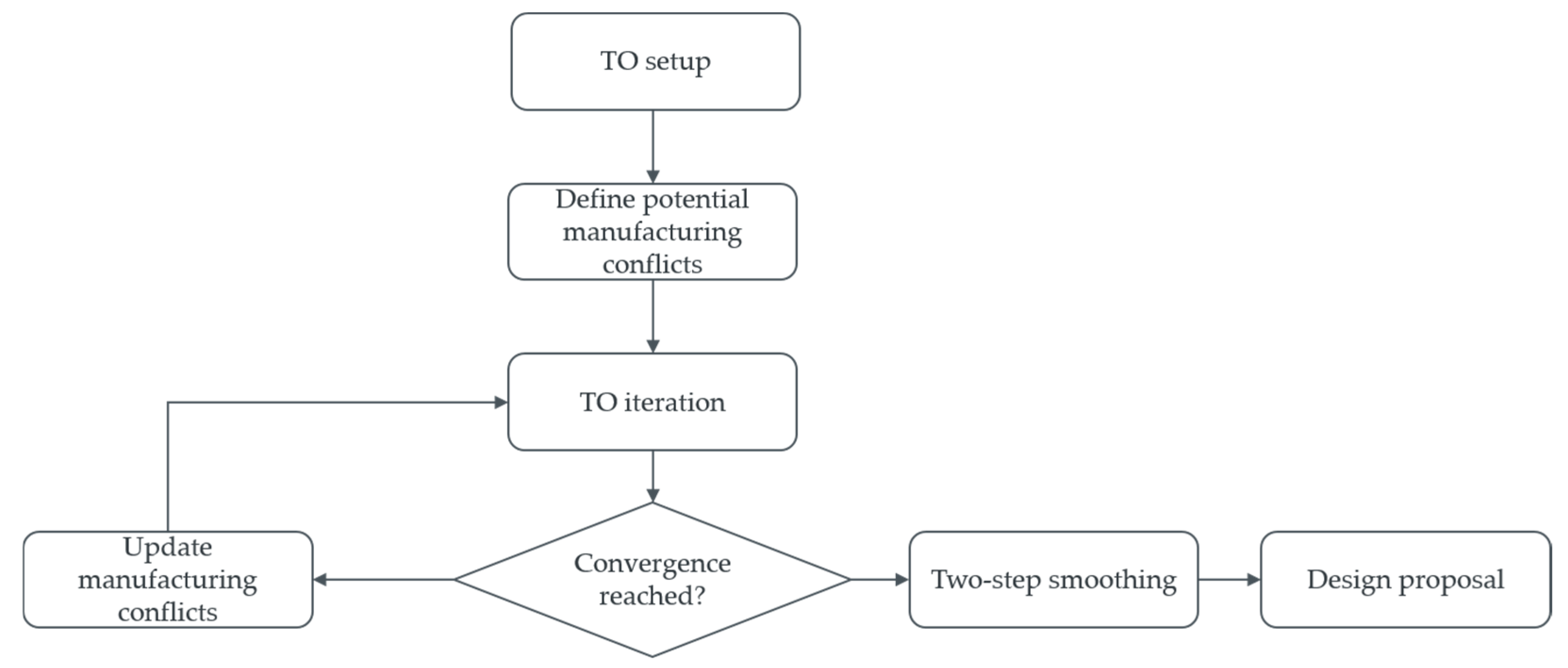
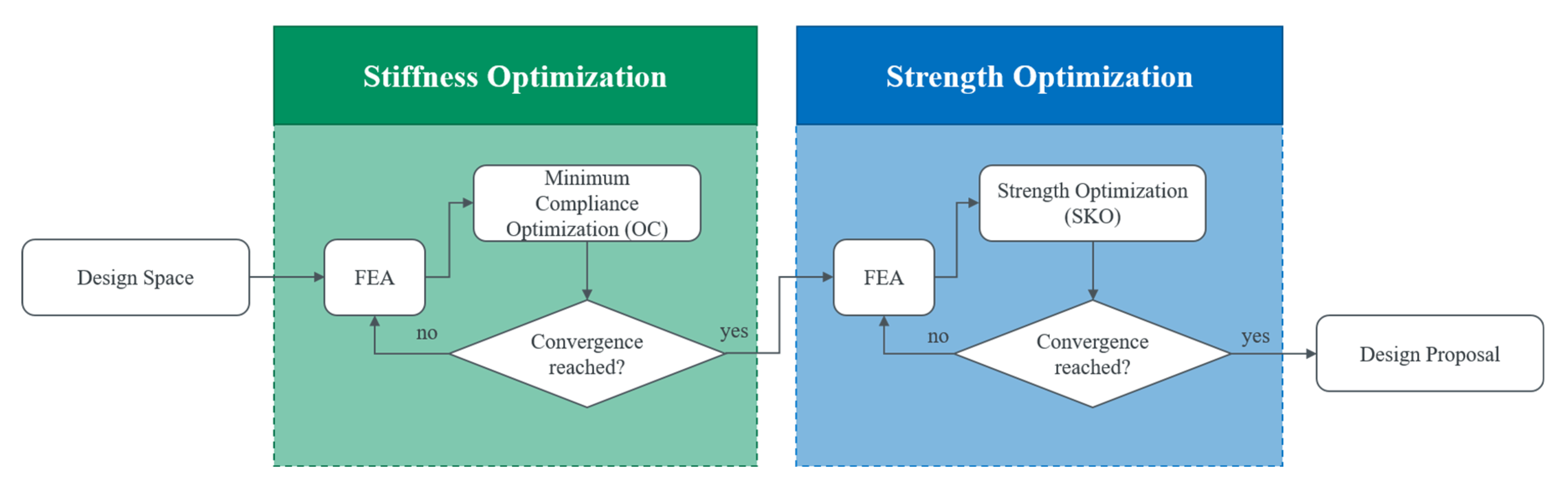
2.1. Topology Optimization
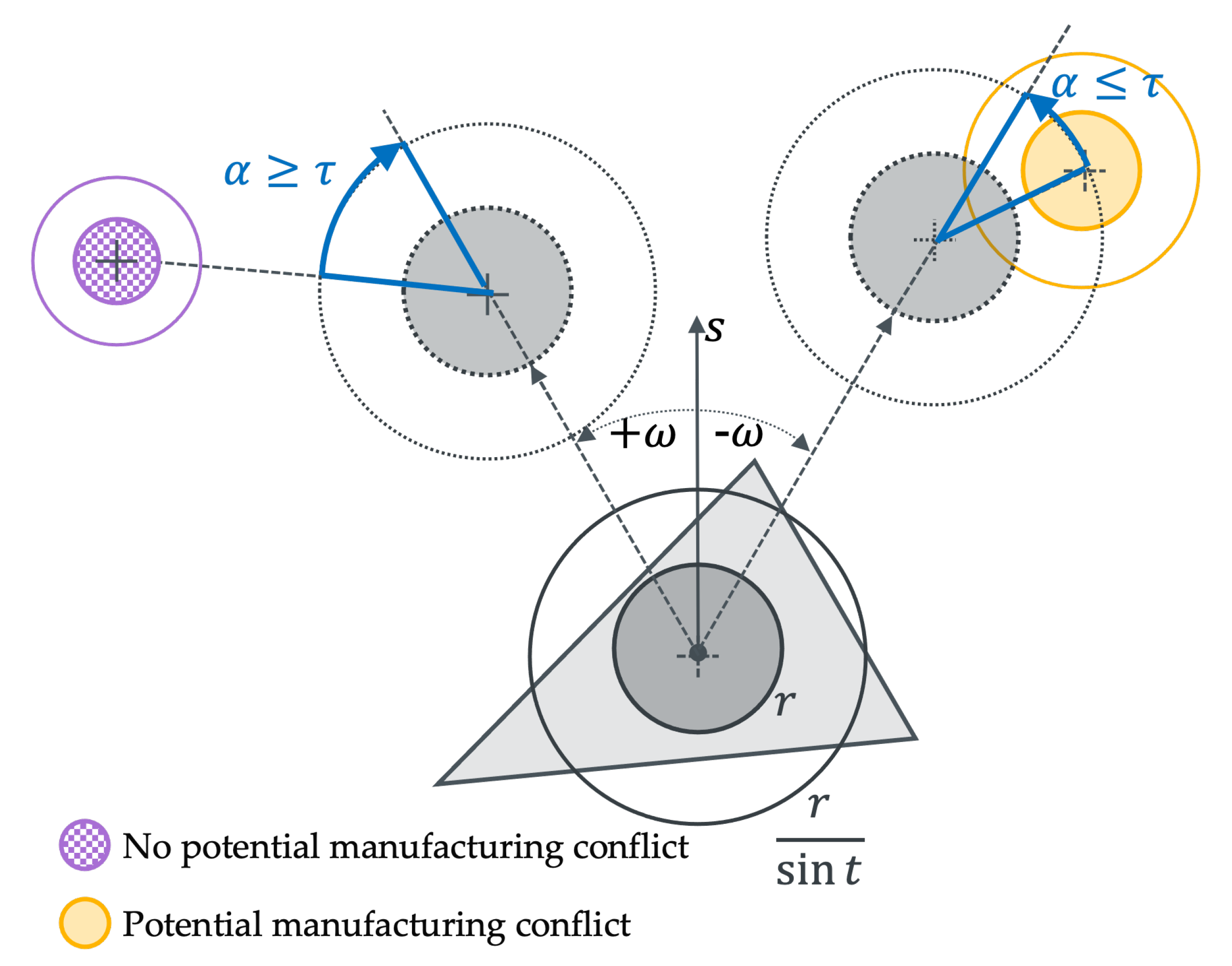
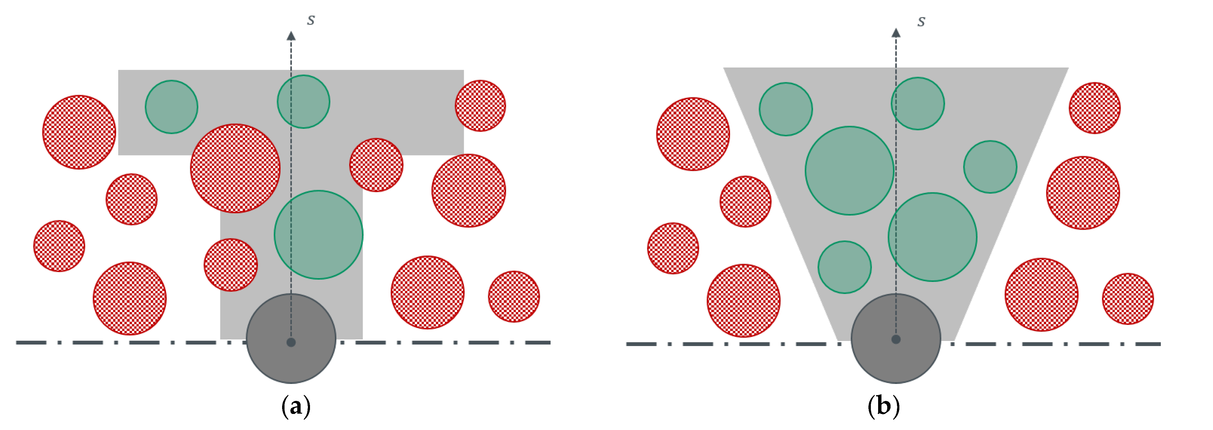
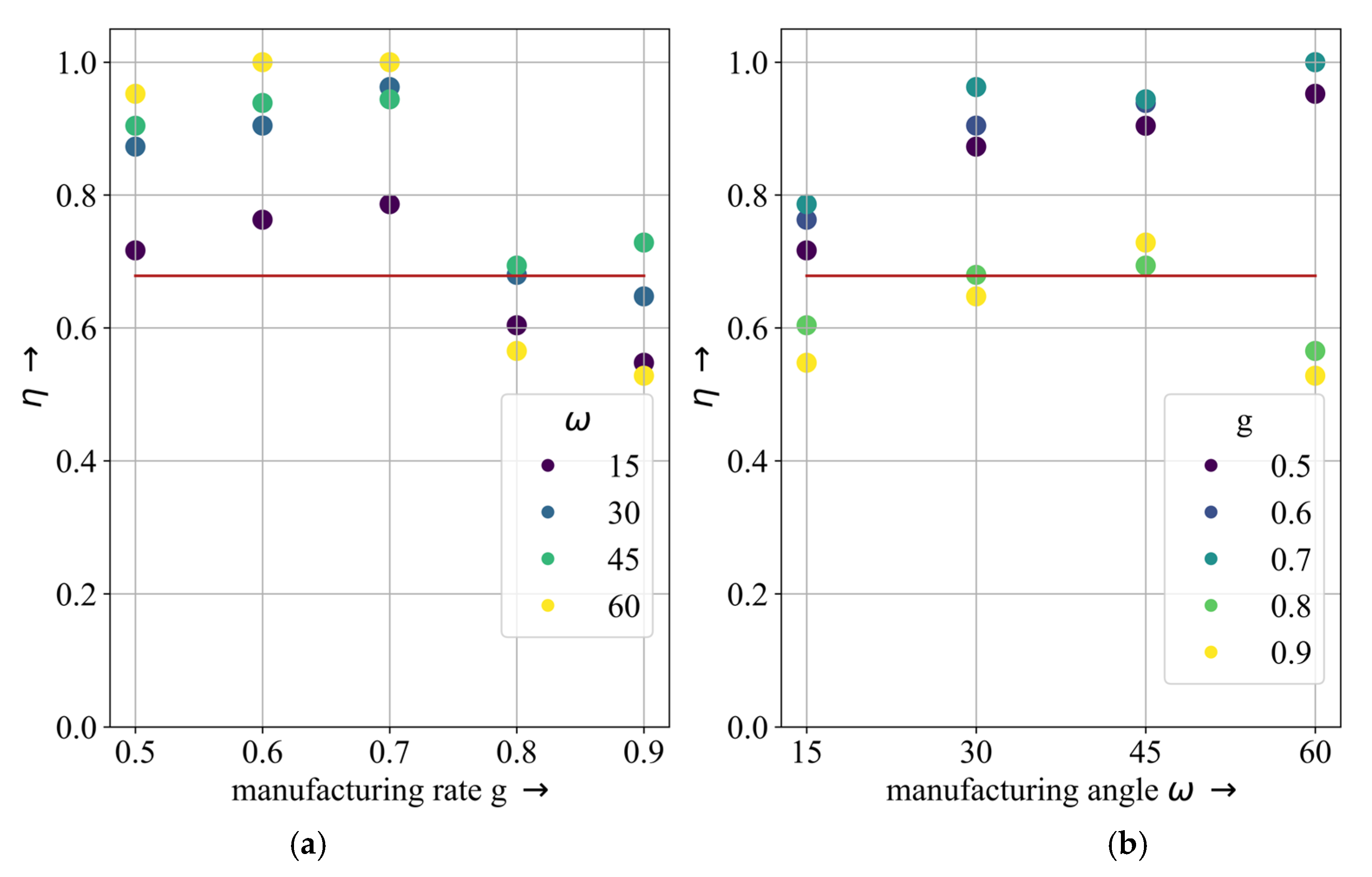
2.2. Manufacturing Constraints
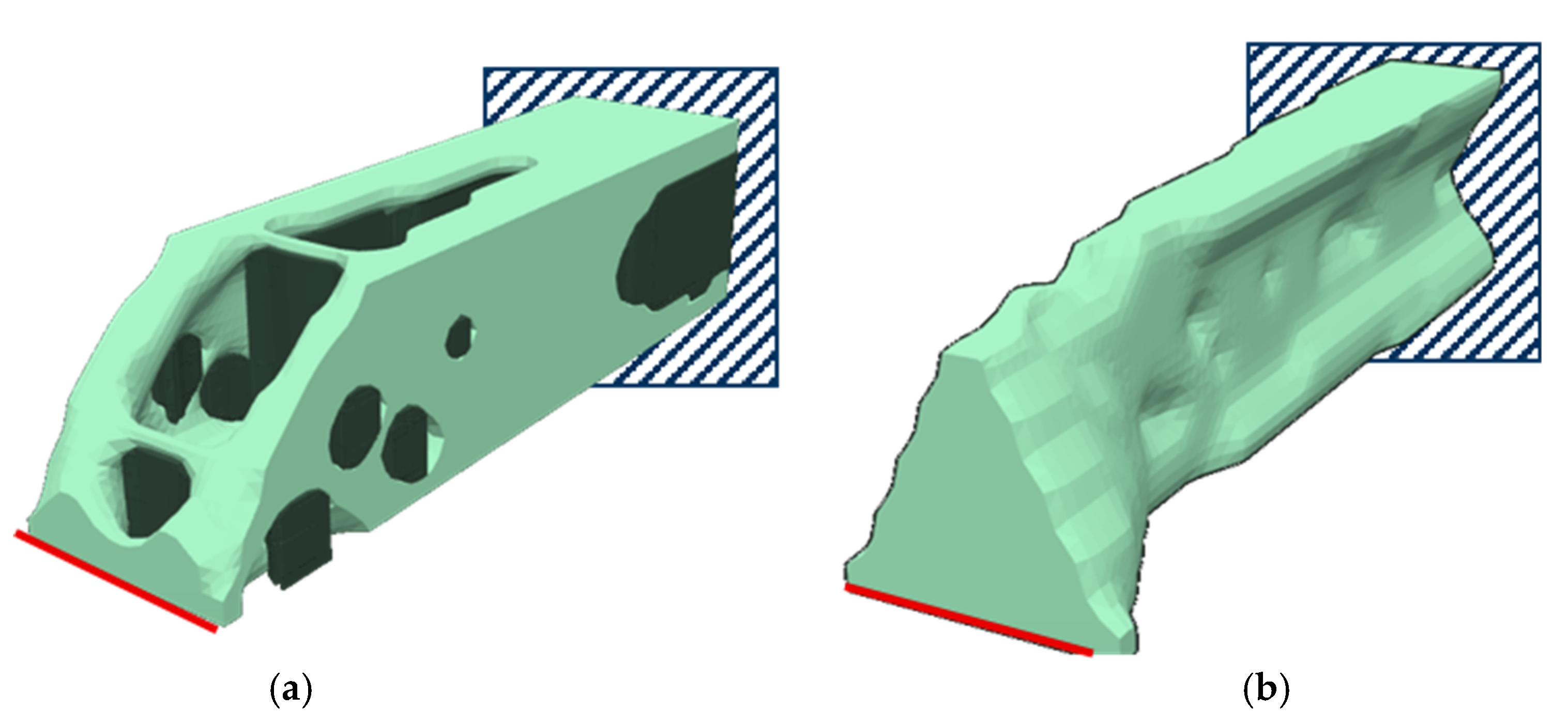
2.3. Smoothing
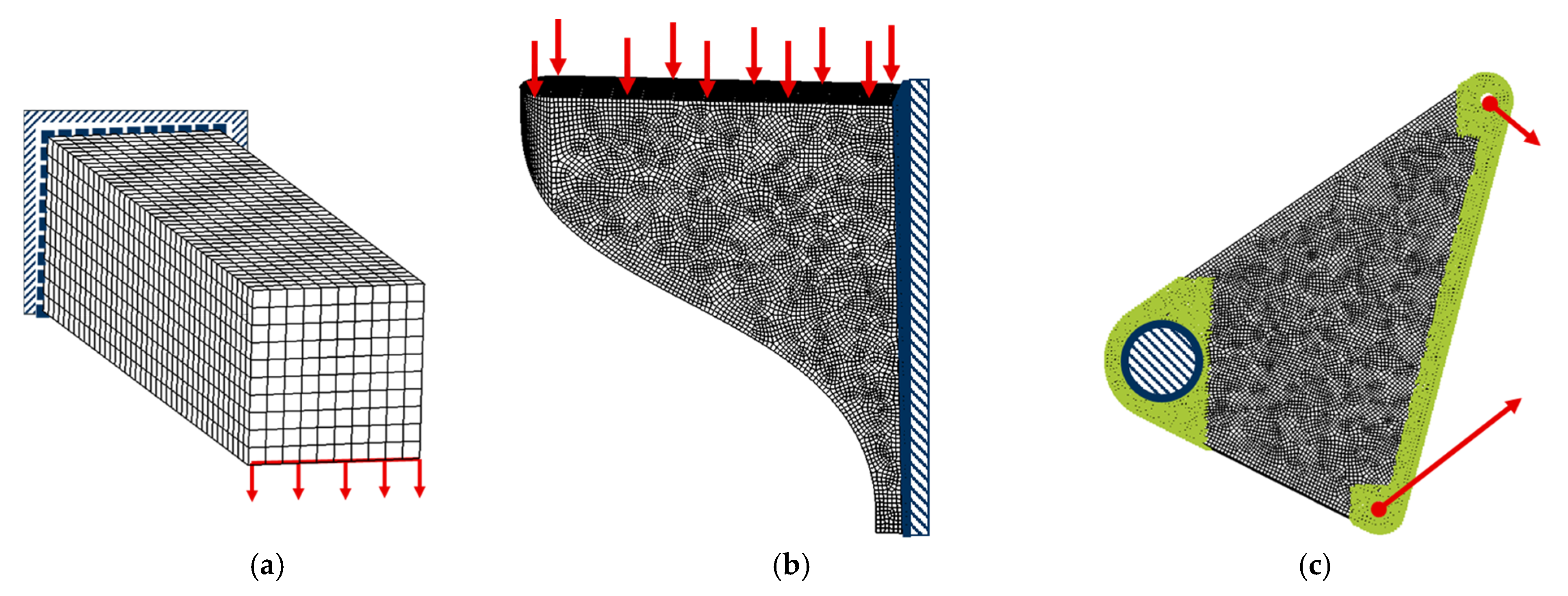
2.4. Application Examples
3. Results
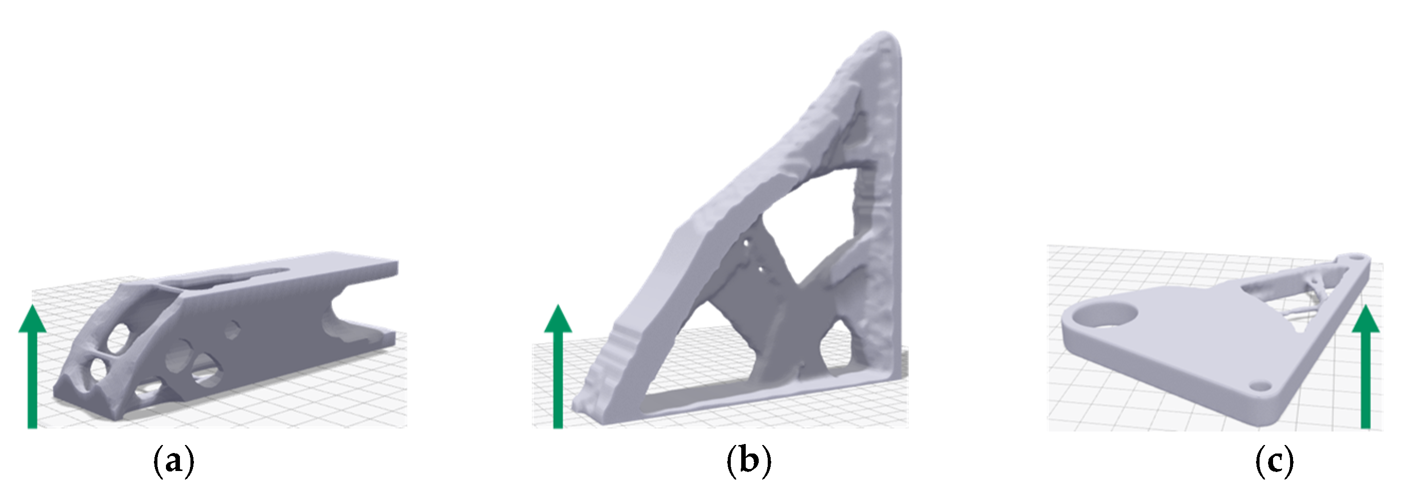
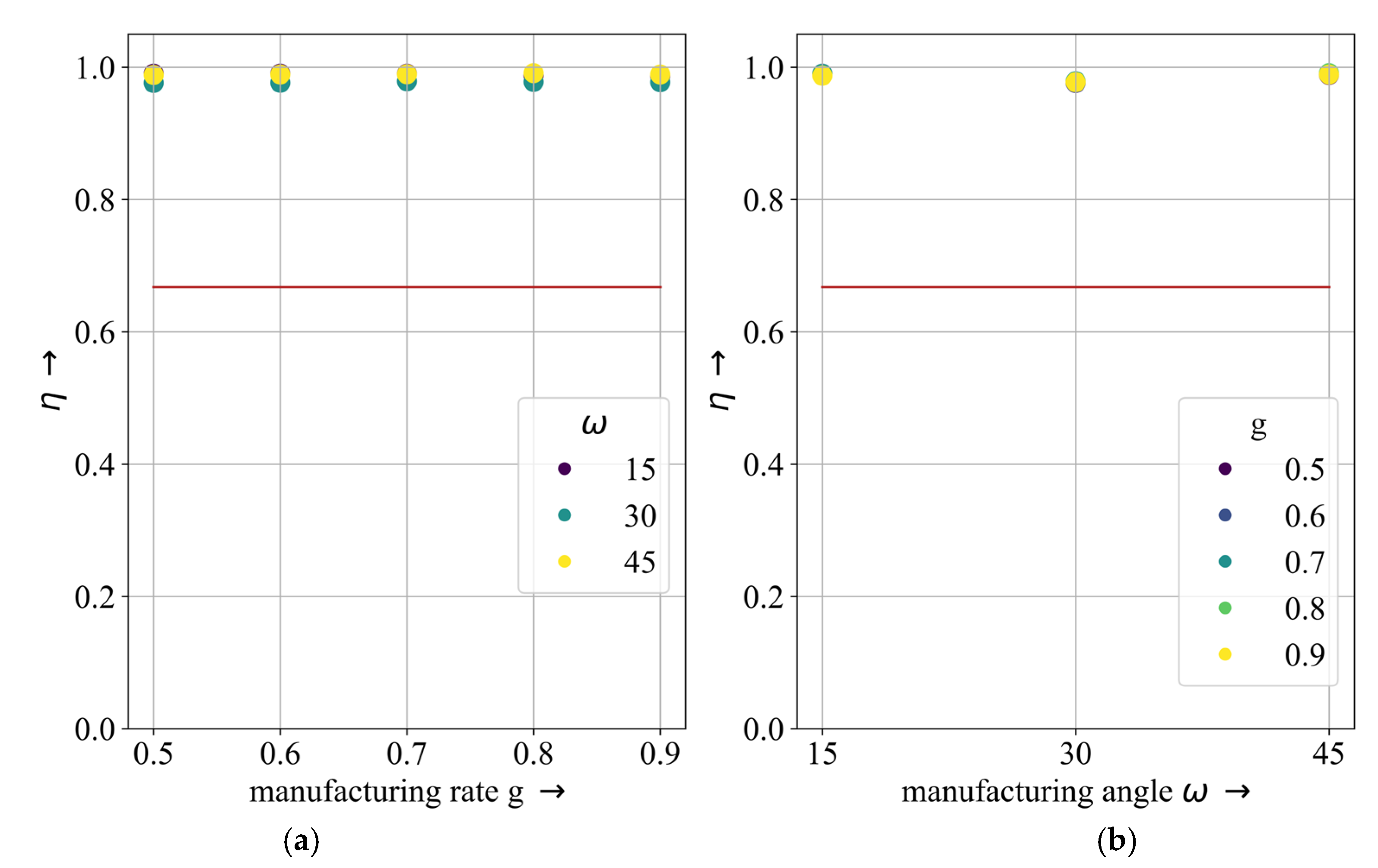
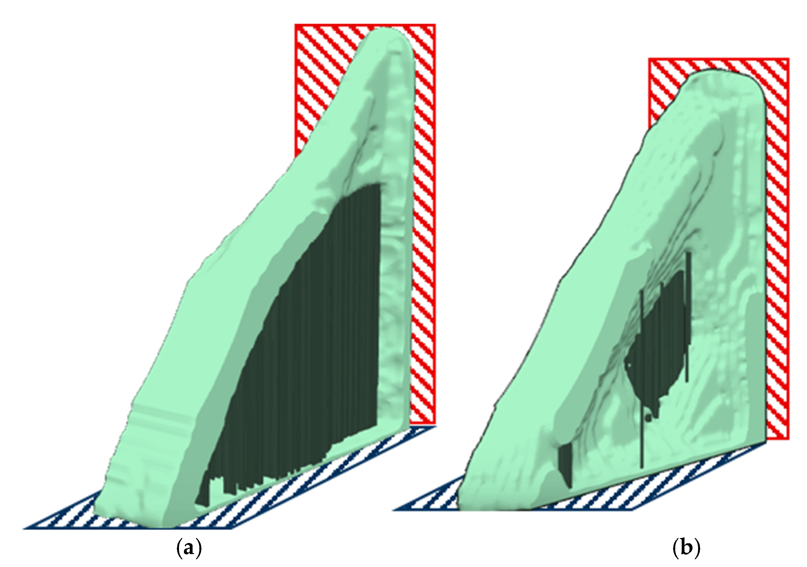
3.1. Cantilever
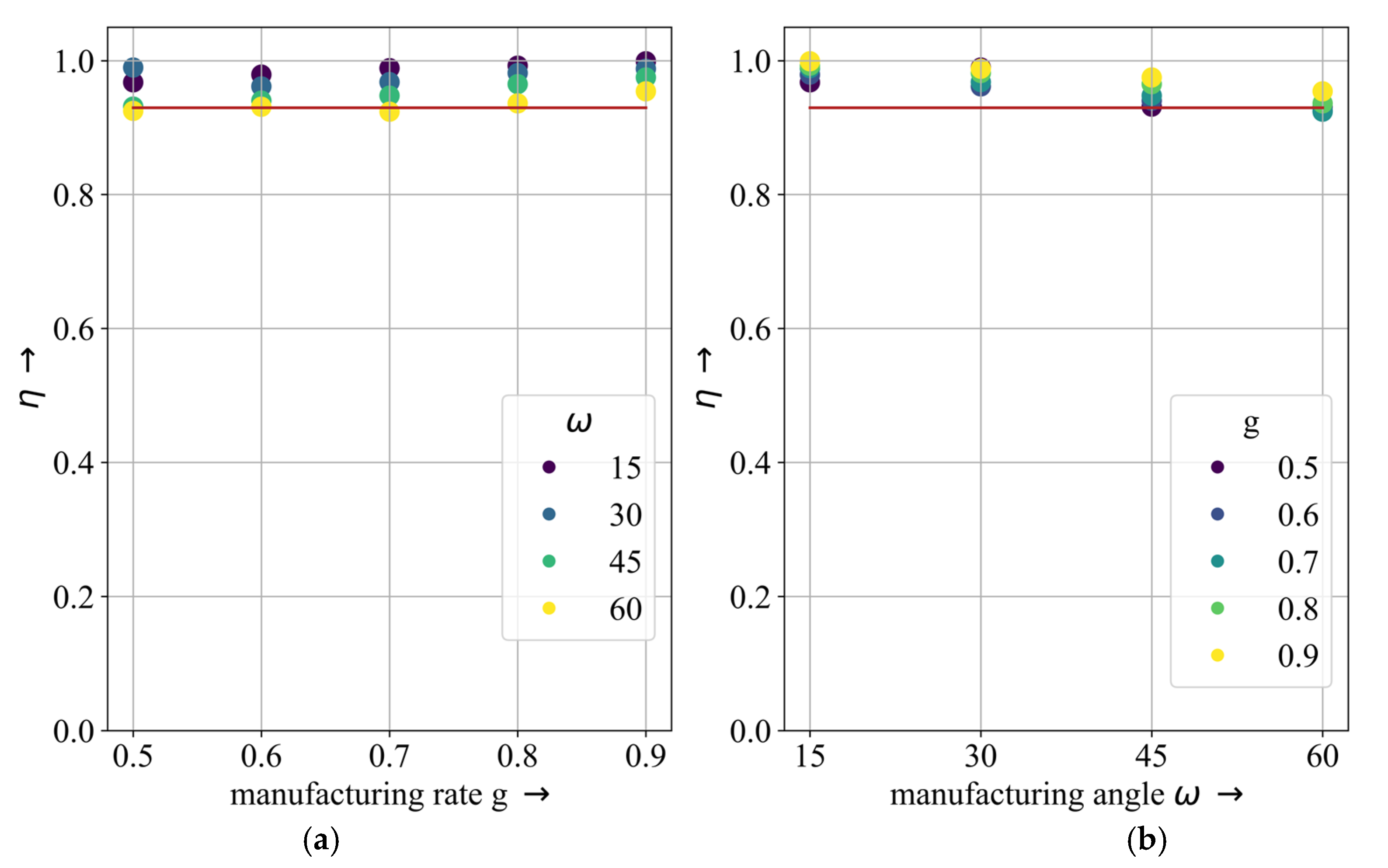
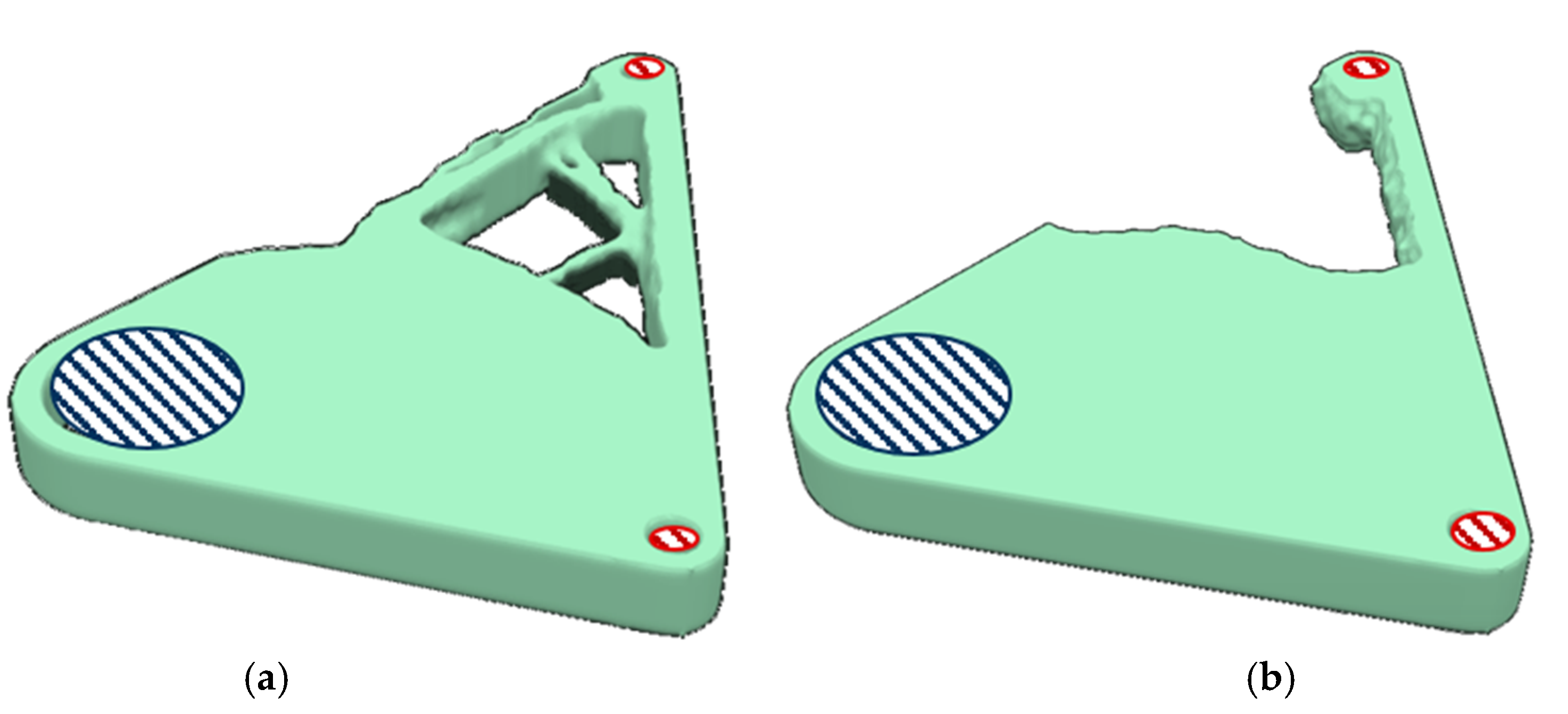
3.2. Bracket
3.3. Rocker
4. Discussion
5. Conclusions
Author Contributions
Funding
Institutional Review Board Statement
Informed Consent Statement
Data Availability Statement
Conflicts of Interest
References
- Bendsøe, M.P.; Sigmund, O. Topology Optimization: Theory, Methods, and Applications; Springer: Berlin/Heidelberg, Germany; New York, NY, USA, 2003; ISBN 978-3-540-42992-0. [Google Scholar]
- Rosnitschek, T.; Hentschel, R.; Siegel, T.; Kleinschrodt, C.; Zimmermann, M.; Alber-Laukant, B.; Rieg, F. Optimized one-click development for topology-optimized structures. Appl. Sci. 2021, 11, 2400. [Google Scholar] [CrossRef]
- Wu, Z.; Xiao, R. A topology optimization approach to structure design with self-supporting constraints in additive manufacturing. J. Comput. Des. Eng. 2022, 9, 364–379. [Google Scholar] [CrossRef]
- Orme, M.; Madera, I.; Gschweitl, M.; Ferrari, M. Topology optimization for additive manufacturing as an enabler for light weight flight hardware. Designs 2018, 2, 51. [Google Scholar] [CrossRef] [Green Version]
- Liu, J.; Ma, Y. A survey of manufacturing oriented topology optimization methods. Adv. Eng. Softw. 2016, 100, 161–175. [Google Scholar] [CrossRef]
- Vatanabe, S.L.; Lippi, T.N.; de Lima, C.R.; Paulino, G.H.; Silva, E.C. Topology optimization with manufacturing constraints: A unified projection-based approach. Adv. Eng. Softw. 2016, 100, 97–112. [Google Scholar] [CrossRef] [Green Version]
- Wang, Y.; Kang, Z. Structural shape and topology optimization of cast parts using level set method: Structural shape and topology optimization of cast parts using level set method. Int. J. Numer. Methods Eng. 2017, 111, 1252–1273. [Google Scholar] [CrossRef]
- Harzheim, L.; Graf, G. A review of optimization of cast parts using topology optimization: II-Topology optimization with manufacturing constraints. Struct. Multidiscip. Optim. 2006, 31, 388–399. [Google Scholar] [CrossRef]
- Wang, C.; Xu, B.; Meng, Q.; Rong, J.; Zhao, Y. Topology optimization of cast parts considering parting surface position. Adv. Eng. Softw. 2020, 149, 102886. [Google Scholar] [CrossRef]
- Gersborg, A.R.; Andreasen, C.S. An explicit parameterization for casting constraints in gradient driven topology optimization. Struct. Multidiscip. Optim. 2011, 44, 875–881. [Google Scholar] [CrossRef]
- Tavakoli, R.; Davami, P. Optimal riser design in sand casting process by topology optimization with SIMP method I: Poisson approximation of nonlinear heat transfer equation. Struct. Multidiscip. Optim. 2008, 36, 193–202. [Google Scholar] [CrossRef]
- Han, Y.; Wang, Q. Numerical simulation of stress-based topological optimization of continuum structures under casting constraints. Eng. Comput. 2022, 38, 4919–4945. [Google Scholar] [CrossRef]
- Gaynor, A.T.; Guest, J.K. Topology optimization considering overhang constraints: Eliminating sacrificial support material in additive manufacturing through design. Struct. Multidiscip. Optim. 2016, 54, 1157–1172. [Google Scholar] [CrossRef]
- Guo, X.; Zhou, J.; Zhang, W.; Du, Z.; Liu, C.; Liu, Y. Self-supporting structure design in additive manufacturing through explicit topology optimization. Comput. Methods Appl. Mech. Eng. 2017, 323, 27–63. [Google Scholar] [CrossRef] [Green Version]
- Leary, M.; Merli, L.; Torti, F.; Mazur, M.; Brandt, M. Optimal topology for additive manufacture: A method for enabling additive manufacture of support-free optimal structures. Mater. Des. 2014, 63, 678–690. [Google Scholar] [CrossRef]
- Perumal, V.I.; Najafi, A.R.; Kontsos, A. A novel digital design approach for metal additive manufacturing to address local thermal effects. Designs 2020, 4, 41. [Google Scholar] [CrossRef]
- Nvss, S.; Esakki, B.; Yang, L.-J.; Udayagiri, C.; Vepa, K.S. Design and development of unibody quadcopter structure using optimization and additive manufacturing techniques. Designs 2022, 6, 8. [Google Scholar] [CrossRef]
- Rastegarzadeh, S.; Wang, J.; Huang, J. Two-scale topology optimization with isotropic and orthotropic microstructures. Designs 2022, 6, 73. [Google Scholar] [CrossRef]
- Tyflopoulos, E.; Steinert, M. Combining macro and mesoscale optimization: A case study of the general electric jet engine bracket. Designs 2021, 5, 77. [Google Scholar] [CrossRef]
- Ryan-Johnson, W.P.; Wolfe, L.C.; Byron, C.R.; Nagel, J.K.; Zhang, H. A systems approach of topology optimization for bioinspired material structures design using additive manufacturing. Sustainability 2021, 13, 8013. [Google Scholar] [CrossRef]
- Plocher, J.; Panesar, A. Review on design and structural optimisation in additive manufacturing: Towards next-generation lightweight structures. Mater. Des. 2019, 183, 108164. [Google Scholar] [CrossRef]
- Saadlaoui, Y.; Milan, J.-L.; Rossi, J.-M.; Chabrand, P. Topology optimization and additive manufacturing: Comparison of conception methods using industrial codes. J. Manuf. Syst. 2017, 43, 178–186. [Google Scholar] [CrossRef]
- Thompson, M.K.; Moroni, G.; Vaneker, T.; Fadel, G.; Campbell, R.I.; Gibson, I.; Bernard, A.; Schulz, J.; Graf, P.; Ahuja, B.; et al. Design for additive manufacturing: Trends, opportunities, considerations and constraints. CIRP Ann. 2016, 65, 737–760. [Google Scholar] [CrossRef] [Green Version]
- Delyová, I.; Frankovský, P.; Bocko, J.; Trebuňa, P.; Živčák, J.; Schürger, B.; Janigová, S. Sizing and topology optimization of trusses using genetic algorithm. Materials 2021, 14, 715. [Google Scholar] [CrossRef] [PubMed]
- Pellens, J.; Lombaert, G.; Lazarov, B.; Schevenels, M. Combined length scale and overhang angle control in minimum compliance topology optimization for additive manufacturing. Struct. Multidiscip. Optim. 2019, 59, 2005–2022. [Google Scholar] [CrossRef]
- Patterson, A.E.; Chadha, C.; Jasiuk, I.M. Identification and mapping of manufacturability constraints for extrusion-based additive manufacturing. J. Manuf. Mater. Process. 2021, 5, 33. [Google Scholar] [CrossRef]
- Van de Ven, E.; Maas, R.; Ayas, C.; Langelaar, M.; van Keulen, F. Overhang control based on front propagation in 3D topology optimization for additive manufacturing. Comput. Methods Appl. Mech. Eng. 2020, 369, 113169. [Google Scholar] [CrossRef]
- Fernández, E.; Ayas, C.; Langelaar, M.; Duysinx, P. Topology optimisation for large-scale additive manufacturing: Generating designs tailored to the deposition nozzle size. Virtual Phys. Prototyp. 2021, 16, 196–220. [Google Scholar] [CrossRef]
- Ameen, W.; Al-Ahmari, A.; Mohammed, M.K. Self-supporting overhang structures produced by additive manufacturing through electron beam melting. Int. J. Adv. Manuf. Technol. 2019, 104, 2215–2232. [Google Scholar] [CrossRef]
- Barroqueiro, B.; Andrade-Campos, A.; Valente, R.A.F. Designing self supported SLM structures via topology optimization. J. Manuf. Mater. Process. 2019, 3, 68. [Google Scholar] [CrossRef] [Green Version]
- Vlah, D.; Žavbi, R.; Vukašinović, N. Evaluation of topology optimization and generative design tools as support for conceptual design. Proc. Des. Soc. Des. Conf. 2020, 1, 451–460. [Google Scholar] [CrossRef]
- Belluomo, L.; Bici, M.; Campana, F. A generative design method for cultural heritage applications: Design of supporting structures for artefacts. Comput. Aided Des. Appl. 2022, 20, 663–681. [Google Scholar] [CrossRef]
- Baumgartner, A.; Harzheim, L.; Mattheck, C. SKO (Soft Kill Option): The biological way to find an optimum structure topology. Int. J. Fatigue 1992, 14, 387–393. [Google Scholar] [CrossRef]
- Frisch, M. Entwicklung Eines Hybridalgorithmus Zur Steifigkeits- UND Spannungsoptimierten Auslegung von Konstruktionselementen; Fortschritte in Konstruktion und Produktion; Shaker Verlag: Aachen, Germany, 2015; ISBN 978-3-8440-4028-9. [Google Scholar]
- Deese, K.; Geilen, M.; Rieg, F. A two-step smoothing algorithm for an automated product development process. Int. J. Simul. Model. 2018, 17, 308–317. [Google Scholar] [CrossRef]


| No. | Example | Algorithm | Manufacturing Rate g | Manufacturing Angle ω | Max. Iterations | Smoothing Iterations |
|---|---|---|---|---|---|---|
| 1 | Cantilever | OC | 0.5–0.9 with ∆ = 0.1 | 15, 30, 45, 60 | 100 | 30 |
| 2 | Bracket | TOSS | 0.5–0.9 with ∆ = 0.1 | 15, 30, 45, 60 | 100 | 30 |
| 3 | Rocker | TOSS | 0.5–0.9 with ∆ = 0.1 | 15, 30, 45, 60 | 100 | 30 |
| Rank | Cantilever | Bracket | Rocker | ||||||
|---|---|---|---|---|---|---|---|---|---|
| g | ω | g | ω | g | ω | ||||
| 1 | 0.6 | 60 | 100% | 0.8 | 45° | 99.10% | 0.9 | 15 | 99.91% |
| 2 | 0.7 | 60 | 100% | 0.6 | 15° | 99.02% | 0.8 | 15 | 99.25% |
| 3 | 0.7 | 30 | 96.25% | 0.5 | 15° | 99.01% | 0.5 | 30 | 98.97% |
Disclaimer/Publisher’s Note: The statements, opinions and data contained in all publications are solely those of the individual author(s) and contributor(s) and not of MDPI and/or the editor(s). MDPI and/or the editor(s) disclaim responsibility for any injury to people or property resulting from any ideas, methods, instructions or products referred to in the content. |
© 2023 by the authors. Licensee MDPI, Basel, Switzerland. This article is an open access article distributed under the terms and conditions of the Creative Commons Attribution (CC BY) license (https://creativecommons.org/licenses/by/4.0/).
Share and Cite
Rosnitschek, T.; Baumann, T.; Orgeldinger, C.; Alber-Laukant, B.; Tremmel, S. Manufacturing Constraints in Topology Optimization for the Direct Manufacturing of Extrusion-Based Additively Manufactured Parts. Designs 2023, 7, 8. https://doi.org/10.3390/designs7010008
Rosnitschek T, Baumann T, Orgeldinger C, Alber-Laukant B, Tremmel S. Manufacturing Constraints in Topology Optimization for the Direct Manufacturing of Extrusion-Based Additively Manufactured Parts. Designs. 2023; 7(1):8. https://doi.org/10.3390/designs7010008
Chicago/Turabian StyleRosnitschek, Tobias, Tobias Baumann, Christian Orgeldinger, Bettina Alber-Laukant, and Stephan Tremmel. 2023. "Manufacturing Constraints in Topology Optimization for the Direct Manufacturing of Extrusion-Based Additively Manufactured Parts" Designs 7, no. 1: 8. https://doi.org/10.3390/designs7010008