Article

Active Vibration Control of Timoshenko Sigmoid Functionally Graded Porous Composite Beam with Distributed Piezoelectric Sensor/Actuator in a Thermal Environment

Laboratory of Advanced Materials Studies and Applications, FS-EST, Moulay Ismail University, Meknes 50050, Morocco
*
Author to whom correspondence should be addressed.
Submission received: 27 October 2022 / Revised: 30 November 2022 / Accepted: 16 December 2022 / Published: 22 December 2022

Abstract

:
This work presents the study of the dynamics and active control of a cantilever sigmoid FGM beam with porosities in a thermal environment. During this study, we considered the Timoshenko beam’s theory combined with the finite element method (FEM). This work also presents a comparative study with an experimental study for the vibration of a functionally graded piezoelectric beam (FGPM) to validate the numerical model. Linear quadratic Gaussian (LQG) optimal control with a Kalman filter was used for the vibration control using piezoelectric sensors and actuators as symmetrical layers to eliminate membrane effects. The controlled and uncontrolled responses are presented, considering the influence of thermal effect, the porosity of the FGM material, and the location of the sensor pair on the smart structure. The results indicate that the porosity effect of the FGM material, as well as the application of the thermal effect, involves an increase in vibration frequencies, in contrast to the increase in the power law index. The study also shows that the thermal and porosity effects result in an increase in vibration amplitudes.

1. Introduction

Mechanical structures are often subject to vibrations from various sources. These vibrations are generally the source of problems affecting the proper functioning of many systems and processes in different industrial sectors and many engineering fields, such as the automotive, aeronautics, and naval industries. [1,2]. These systems have been increasingly integrating composite materials in the manufacture of structures. Additionally, excessive levels of vibration amplitude can lead to a number of problems such as structural damage due to damage or fatigue. One of the solutions to this problem is active vibration control (AVC) [3]. Over the past 30 years, the active control of noise and vibration has focused on the use of new concepts. With the advent of MEMS and NEMS technologies, as well as so-called “adaptive” materials, it is possible to consider the realization of complex and varied structures. These techniques greatly improve the quality of intelligent systems and structures. In the case of thin structures, piezoelectric transducers bonded to the structure are often used [4,5,6,7,8]. There are many examples of systems in which active vibration control can be applied, such as fans, vehicle interiors, precision equipment, combustion engines, electric and hydraulic drives, vehicle transmission units, barriers and acoustic enclosures, etc. [9,10,11,12]. Otherwise, it is important to mention that thin-walled composite beams occupy a significant number of applications in aerospace engineering and other industries. Recently, different types of composite materials were widely used in structures, with specific mechanical and thermal characteristics. Functionally graded materials (FGM) are a type of composite materials whose composition and structure change gradually in volume, which leads to corresponding changes in the material’s properties [13]. The purpose of FGMs is to eliminate the interface problems that exist in traditional composite materials, and replacing them with an interface that gradually changes and resulting in a change in the chemical composition of the composite in that interface region. These types of composites are, therefore, well known and widely used in many technical applications as materials that are resistant to very high temperatures [14]. The sigmoid law describes the variation in the volume fraction of an S-FGM structure using two functions of the power law to ensure a good stress distribution between all interfaces [15]. In general, the sigmoid law is not often used in the same way as the power law. However, during the manufacture of FGMs, micropores or voids may appear in the material during the sintering process (porosity). This is due to the large difference in the solidification temperatures between the material components [16].
Several researchers have studied free and forced vibrations, vibrational control of FGM structures, and piezoelectric materials. Hong et al. developed a model for bending and wave propagation [17] and the bending and vibration analysis of functionally graded magneto-electro-elastic Timoshenko microbeams [18]. Yang et al. studied the free damping vibration of piezoelectric cantilever beams and its experimental verification [19]. Jing et al. studied the vibration analysis of piezoelectric cantilever beams with bimodular functionally graded properties [20]. Sharma studied the vibration analysis of a Timoshenko FGP beam, while considering that the electromechanical properties will change continuously through the thickness based on the power law [21]. Zhang et al. studied the bending and vibration of a flexoelectric beam structure on linear elastic substrates [22]. Doroushi et al. investigated the free and force vibration of FGP beam using the HOSD theory. In this study, the materials properties were assumed to vary through thickness direction based on the power law [23]. Based on the Rayleigh–Ritz method and torque stress theory, Kang et al. studied the dynamic characteristics of piezoelectric micromachined ultrasonic transducers [24]. Njim et al. analyzed the buckling of a simply supported rectangular FGM plate loaded in the plane by presenting a new analytical model [25]. Redddy et al. used the HOSDT for the development of formulations and analytical solutions to analyze the free vibration of FGP plates [26]. Bendine et al. studied the AVC of FG beams using bonded piezoelectric layers and the HOSD theory. The material properties changed through the thickness based on the power law [10]. El Harti et al. studied the AVC of an FG sandwich beam with symmetrical piezoelectric sensors/actuators [11], and they also developed a finite element (FE) model of vibration control for a Timoshenko exponential FGM beam with distributed piezoelectric sensors/actuators [27]. Maruani et al. studied the static and active vibration control of a Timoshenko FGP beam. The materials’ properties changed continuously through the thickness based on the power law, and the simulation of the (AVC) was performed using a linear quadratic regulator method [28]. Li et al. investigated the vibration control of a rotating-flexible FGM beam using the high-order coupling theory. The effect of the temperature variation on the free vibration was studied, and the materials’ properties varied through the thickness direction based on the power law [29]. Ebrahimi et al. analyzed the thermo-mechanical vibration behaviors of non-uniform porous FGM beams under different thermal loads [30]. Esen et al. treated a Timoshenko S-FGM beam model using non-local strain gradient theory to study and analyze its free vibrations and dynamic responses under moving loads [31], and they subjected it to a moving mass [32]. Bodaghi et al. studied the nonlinear active control of the dynamic response of FG beams in thermal environments based on the FOSD theory. In this study, the material properties varied in the thickness direction according to the power law [33]. Kumar and Harsha used the first-order shear deformation theory (FSDT) with Hamilton’s principle to investigate the static and vibrational responses of a porous S-FGP plate under thermoelectric loading [34]. El Harti et al. treated the active control of a porous Euler-Bernoulli FGM beam under a thermal load with piezoelectric symmetrically bonded materials [35], and they completed a dynamic analysis of the active control of the distributed piezothermoelastic FGM composite beam with porosities modelled by the finite element method [36]. New numerical methods as robust as the FEM can be proposed for the structural dynamics analysis and vibration control of an S-FGM beam, such as the “Differential Quadrature” method and the “Bezier” method. Yan et al. studied the free vibration analysis of composite beams and plates by a novel hierarchical differential quadrature finite elements method [37]. Kabir and Aghdam developed a Bezier-based multi-step method for finding the nonlinear vibration and post-buckling configurations of Euler–Bernoulli composite beams [38]. Sharma, in his review, dealt with vibration characteristics of functionally graded piezoelectric material (FGPM) beams. The literature review revealed that very few works were available on the vibration analysis of an FGPM beam where the material properties were assumed to vary continuously in the thickness direction according to an exponential and sigmoid law [39]. Shivashankar and Gopalakrishnan presented a review on the use of piezoelectric materials in active vibration, noise, and flow control [40]. Currently, there are over 420 papers on the use of piezoelectric materials for active control, but none of them use FGM materials according to the sigmoid law.
This paper is an extension of our previous works [11,27,35,36]. The novelty of this work is manifested in its study of the active vibration control of sigmoid functionally graded porous beams in a thermal environment using Timoshenko’s beam theory combined with FEM. The use of symmetrical layers of piezoelectric materials eliminates the membrane effect. The objective of this work is to conduct an analysis of the structural dynamics of a sigmoid functionally graded porous beam in a thermal environment using Timoshenko’s beam theory. Then, the AVC with piezoelectric sensors and actuators is analyzed using the linear quadratic Gaussian (LQG) control and Kalman filtering.

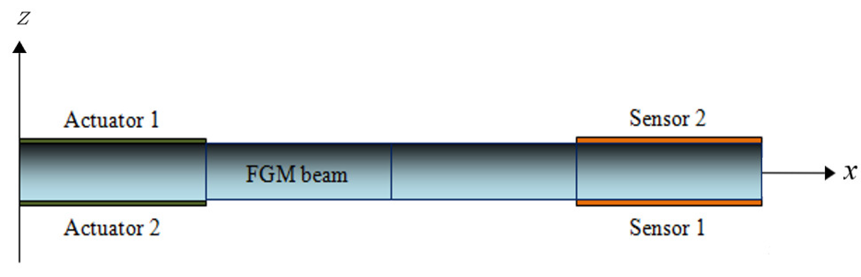
2. Mathematical Modeling

A uniform FGM beam with porosities of length L , width b , and thickness h is considered in this paper, as shown in Figure 1.
The lower surface of the FGM beam, z = h / 2 , is a metal layer, and the upper surface, z = + h / 2 , is a ceramic layer. The sigmoid law is considered to describe the variation in the materials’ properties in the thickness direction (z-axis), which is defined by [15]:
V c z = 1 2 h 2 + z h / 2 k 1 1 2 h 2 z h / 2 k                                                 h 2 z 0 0 z h 2 V c = 1 V m
where V c and V m are the volume fractions of the ceramic and metal, respectively, and k is the exponent of the volume fraction. The Young’s modulus E and mass density ρ of the S-FGM with porosities, as presented in [15], are defined by:
E z = E m + E c E m 1 2 h 2 + z h / 2 k n 2 E c + E m h 2 z 0 1 1 2 h 2 z h / 2 k n 2 E c + E m 0 z h 2
ρ z = ρ m + ρ c ρ m 1 2 h 2 + z h / 2 k n 2 ρ c + ρ m h 2 z 0 1 1 2 h 2 z h / 2 k n 2 ρ c + ρ m 0 z h 2
where n is the porosity index, with different values n = 0.1 ;   0.2 , and for a perfect FGM beam, n = 0. The constitutive equation for a piezo-thermoelastic laminate is given by [34,35,41]:
σ = C E ε α θ e E
where α is the coefficient of thermal expansion given by α = ρ c 0 θ 0 , and c 0 and θ 0 are the specific heat and the initial temperature, respectively.
Considering the Timoshenko beam’s theory, the displacement in the x , y , and z directions of the beam can be written as follows [35,42]:
u x , y , z , t = z ψ x , t υ x , y , z , t = 0 w x , y , z , t = w x , t
where w and u are transverse and axial displacements, respectively, and ψ is the rotation. The nonzero components of strain can be written as [42,43]:
ε x x = z ψ x                       γ x z = z w x + ψ
The strain energy U and the kinetic energy T of the element are given as follows [26]:
U = 1 2 0 l ψ x w x + ψ T E I 0 0 K G A ψ x w x + ψ d x
T = 1 2 0 l w t ψ t T ρ A 0 0 ρ I w t ψ t d x
where G is shear modulus and K = 10 1 + υ / 12 + 11 υ , being the shear coefficient [27,44].
The total work W e due to the external forces in the beam is given by [27]:
W e = 0 l w ψ T q d m d x
where q d and m represent the distributed force and the moment along the length of the beam, respectively. The equations of motion are derived via the Hamilton’s principle:
δ Π = t 1 t 2 δ U δ T δ W e d t = 0
In the static case, without external forces acting on the beam, the equations of motion modeled by Timoshenko’s theory are as follows [27]:
K G A w x + ψ x = 0
E I ψ x x K G A ψ x + ψ = 0

3. Finite Element Formulation

The transversal displacement w x , t and its first and second spatial derivatives are given by [11,27]:
w x , t = N w q                                 w ˙ x , t = N ψ q                                                     w ¨ x , t = N a q
with
q = w 1 ψ 1 w 2 ψ 2 T
where q is the nodal coordinate vector, q ˙ is its temporal derivative, and N w T , N ψ T , and N a T are the shape functions for the displacements, rotations, and accelerations, respectively, as presented in Appendix A.
The equation of motion is presented by [27]:
M q ¨ + K q = f
where the elementary mass and stiffness matrices of the piezoelectric and FGM elements are expressed, respectively, by [27]:
M s / a = 1 2 0 l s / a N w N ψ T ρ s / a A s / a 0 0 ρ s / a I s / a N w N ψ d x
M F G M = 1 2 0 l b N w N ψ T C 1 0 0 C 2 N w N ψ d x
K s / a = 1 2 0 l s / a N ψ x N w x + N ψ T E s / a I s / a 0 0 K G s / a A s / a N ψ x N w x + N ψ d x
K F G M = 1 2 0 l b N ψ x N w x + N ψ T C 3 0 0 C 4 N ψ x N w x + N ψ d x
where the (s/a) notation denotes the sensor/actuator element, ρ s / a and A s / a are the density and cross-sectional area of the sensor and actuator, respectively, and C 1 , C 2 , C 3 , and C 4 are the constants that depend on the characteristics of the FGM material, given as [27]:
C 1 = b 0 h ρ z d z C 2 = b 0 h ρ z z 2 d z C 3 = b 0 h E z z 2 d z C 4 = b 0 h K G z d z
The elementary matrices of mass and stiffness are given by [27]:
M = M F G M + M s + M a                               K = K F G M + K s + K a

4. Piezoelectric Constitutive Equations

The direct and inverse piezoelectric constitutive equations are given by [45,46]:
D z = d 31 σ + e σ E f                                             D z = d 31 E f + S e σ
where D z , d 31 , σ , e , E f , and S e are, respectively, the electric displacement, piezoelectric constant, strain, dielectric constant, electric field, deformation, and the compliance of the piezoelectric medium.
The voltage will be applied as an input to the actuators with a precise gain, depending on the degree of damping required, as follows [27]:
V s t = G c e 31 z b 0 l p n 1 T q ˙ d x
V 1 s t = S s 0 1 0 1   q ˙
V 2 s t = S s 0 1 0 1   q ˙
where S s = G C e 31 z b is the sensor constant and G C is the signal conditioning gain [27].
The final equations of the two sensors can be written in the form shown below:
V 1 s t = V 2 s t = p T q ˙
where p is a constant vector that depends on the characteristics of the sensor and its location. The control input u is given as:
u = G a i n   c o n t r o l × V s
The control force f c t r produced by the actuator is given by [27]:
f c t r 1 = h u t = V 1 a t
f c t r 2 = h u t = V 2 a
h T = E p d 31 b z ¯ 1 0 1 0 = a c 1 0 1 0
and a c = E p d 31 b z ¯ is the actuator’s constant, while h is the actuator’s constant vector.
Similarly, the force due to the thermoelastic coupling f t h is given by [27,35,36,47]:
f t h = A   N θ T λ N θ θ d A
If the beam is also subjected to an external force f e x t , the total force vector applied to the beam becomes:
f t = f e x t + f c t r 1 + f c t r 2 + f t h

5. Dynamic Equation and State Space Model

The equation of motion of the entire structure and the control equation using generalized coordinates are written, respectively, as:
M T g ¨ + K T g = f e x t + f c t r 1 + f c t r 2 + f t h = f t
y i t = V i s t = p i T q ˙ = p i T T g ˙
Pre-multiplying Equation (33) by T T , ( T being the modal matrix) the equation can be reformulated as follows:
M g ¨ + K g = f e x t + f c t r 1 + f c t r 2 + f t h
where M and K are the generalized mass and stiffness matrices, respectively.
Using Rayleigh’s proportional damping [48,49]:
C = α M + β K
The dynamic equation of the structure and the control equation are, finally, given by [27,35,36]:
M g ¨ + C g ˙ + K g = f e x t + f c t r 1 + f c t r 2 + f t h
The state space model in the MIMO mode is given by:
x ˙ = A x t + B u t + E r t
y t = C T x t + D u t
where r t , u t , A , B , C , D , E , x t , and y t represent the external force input, the control input, the system matrix, the input matrix, the output matrix, the transmission matrix, the external load matrix, the state vector, and the system output (sensor output), respectively.
To determine the matrix of the gains G , the optimal control proposed to minimize a performance index J is defined by [35]:
m i n G   J = 0 x Q x + u R u d t
where Q and R are, respectively, the matrices of the defined semi-positive and the defined positive weighting on the outputs and control inputs [35].
The optimal G gain matrix can be written as [35]:
G = R 1 B T P
where the matrix P is the asymptotically optimal solution of the Riccati equation:
Q A T P P A + P B R 1 B T P = 0
The LQG control method an optimal control procedure that uses a Kalman filter as an observer and a controller that minimizes a cost function of the quadratic form [27,35,50]. The LQR and LQG methods can be used with MATLAB software to calculate control gains. This work used MATLAB software to solve the Riccati equation and obtain the gain of control for the LQR control methods.

6. Validation Study

In order to validate our numerical model, we needed to take nearly the same parameters used in the theoretical model of [20] and the experimental results of [19] (Table 1). We used a perfect FGM beam, with k = 0.2, made of two types of piezoelectric materials (with nearly the same characteristics). The first material is that of the piezoelectric actuator (Table 2) and the second is that of the PZT-5 (density of 7500 kg∙m3), as used in [19,20]. The dimensions of the beam shape are l × b × h = 0.05 × 0.02 × 0.0001   m 3 .
Table 1 shows the vibration frequencies of the experimental measurement [19] and the theoretical solution [20] with the results of this study.
The theoretical results agree with the experimental results, though there are some differences between them, including an error of 7.7% which indicates that the expression of the given vibration frequency is correct.

7. Results and Discussions

The aim of this study was to analyze the dynamic behavior of a smart structure with dimensions of 0.2 × 0.02 × 0.005 m 3 , composed of an imperfect S-FGM beam bonded on both surfaces of four layers of piezoelectric materials and functioning as sensor/actuator. This study presents the results of the dynamics and active control using an optimal LQG control method with a Kalman filter. The geometric and physical characteristics of the different materials are presented in Table 2. The temperature and porosity effects of the FGM material were taken into account. The controlled and uncontrolled responses and the vibration frequencies are presented. The structure was subjected to an excitation force in the form of a pulse of (1N) applied at the free end of each model. In this work, we considered a uniform thermal loading, with ΔT = 5 [K].
Figure 2 compares the controlled (Figure 2b) and uncontrolled (Figure 2a) impulse responses. The figures also show a comparison of the FGM material porosities for n = 0 ; 0.1 ; 0.2 . The sensor pair is in finite element two, and the power law index is k = 0.5 .
Table 3 presents the vibration frequencies of the smart structure as functions of the power law index,   k = 0.2 : 5 , and also as functions of the porosity index for n = 0 ; 0.1 ; 0.2 .
According to Figure 2, an increase in vibration amplitudes was observed by the increasing the porosity index. From Table 3, it can be seen that the vibration frequencies decreased with the increasing power law index k , and also by the increasing porosity index n for k 2 . This was due to the fact that the increase in the exponent of the power law led to decreases in the bending stiffness and the modulus of elasticity, given that the natural frequencies were proportional to the modulus of rigidity [30,35]. It was also noticed that the application of the thermal effect implied a decrease in vibration frequency. This is because the increase in temperature reduced the stiffness of the beam material while the mass density remained constant, which explains the decrease in vibration frequency.
Figure 3 shows the impulse responses of the smart structure. The sensor pair is located on finite element three. The figure on the left shows a comparison of the controlled and uncontrolled responses for a perfect FGM material n = 0 , while the figure on the right shows the impulse response for a porous material n = 0.2 , as well as the application of the thermal gradient. From this comparison, we can see that the porosity and thermal effects imply remarkable increases in the vibration amplitudes on the dynamics of the structure.
Similar to the previous table, Table 4 shows the decreases in vibration frequencies after increasing the power index k and after decreasing the porosity index for ( k < 2 ) , as well as the application of the thermal effect, which implied a decrease in vibration frequency. These results are similar to those of [30]. The displacement of the actuator pairs at the free end also implied decreases in the vibration frequencies.
Figure 4 shows a comparison between the uncontrolled responses (shown on the right) and the controlled responses (shown on the left), with the thermal gradient applied in this case and the pair sensors in finite element four.

8. Conclusions

This study analyzed the active vibration control of an imperfect S-FGM beam in a thermal environment using piezoelectric materials as a co-located sensor/actuator pair to eliminate the membrane effect. The Timoshenko beam theory was used in this study to consider the effects of first-order shear deformation and axial displacements. The equations of motion were derived via the Hamilton principle, and the vibration frequencies were found by solving the eigenvalue problems. The results of the dynamics and vibration control were presented using the application of the linear quadratic Gaussian control (LQG) method with Kalman filtering, as summarized in Figure A1. The sigmoid law was considered to describe the variation in the properties of the FGM material according to its thickness. According to the results, it was found that the porosity effect of the FGM material for k 2 , as well as the application of the thermal effect, implied a decrease in vibration frequency. This is because the increase in temperature reduced the material stiffness of the beam. The increase in the power law index also implied a decrease in vibration frequency. This decrease in vibration frequency was because the increase in the k index led to a decrease in the modulus of elasticity. We have also shown that the thermal and porosity effects led to an increase in vibration amplitude. The study also presented the influence of changing the location of the pair sensor on the smart structure from EF 2 to EF 4.

Author Contributions

Conceptualization, M.R. and K.E.H.; methodology, K.E.H.; software, M.R.; validation, K.E.H. and M.R.; formal analysis and investigation, R.S.; writing—original draft preparation, K.E.H.; writing—review, supervision, and editing, M.R.; visualization, R.S. All authors have read and agreed to the published version of the manuscript.

Funding

This research received no external funding.

Conflicts of Interest

The authors declare no conflict of interest.

Appendix A

The shape functions (for displacements, rotations, and accelerations), taking the bending stiffness of the beam and the shear stiffness, are given as follows:
N w T = 1 1 + ϕ 2 x l 3 3 x l 2 ϕ x l + 1 + ϕ l 1 + ϕ x l 3 2 + ϕ 2 x l 2 + 1 + ϕ 2 x l 1 1 + ϕ 2 x l 3 2 x l 2 ϕ x l l 1 + ϕ x l 3 1 ϕ 2 x l 2 ϕ 2 x l  
N ψ T = 6 1 + ϕ l x l 2 x l ϕ 1 1 + ϕ 3 x l 2 4 + ϕ x l + 1 + ϕ 6 1 + ϕ l x l 2 x l 1 1 + ϕ 3 x l 2 2 ϕ x l  
N a T = 6 1 + ϕ l 2 x l 2 1 l 1 1 + ϕ l 6 x l 4 + ϕ 1 1 + ϕ l 6 x l 2 1 l 1 1 + ϕ 6 x l 2 2 ϕ l  
where ϕ is the ratio between the bending stiffness of the beam and the shear stiffness, and it is given by:
ϕ = 12 l 2 E I K G A = 24 l 2 I K A 1 + ν

Appendix B

Figure A1 presents the method used in the study of smart beams after the definition of the material properties (choice of piezoelectric sensor/actuator and FGM (laws of variation and porosity). The modeling of the structure consisted of using the Timoshenko theory combined with the finite element method (FEM), which was applied to the intelligent structure. This modeling allowed us to construct the mass and stiffness matrices of the piezoelectric elements and the FGM element.
Figure A1. Synoptic presenting the method used in the study of the smart beams.
Designs 07 00002 g0a1

References

  1. Bouhedma, S.; Hu, S.; Schütz, A.; Lange, F.; Bechtold, T.; Ouali, M.; Hohlfeld, D. Analysis and Characterization of Optimized Dual-Frequency Vibration Energy Harvesters for Low-Power Industrial Applications. Micromachines 2022, 13, 1078. [Google Scholar] [CrossRef] [PubMed]
  2. Li, Z.; Liu, L.; Wang, P.; Liu, Y.; Wei, X.; Xu, Q.; Sun, H. Modeling and Analysis of Radial Electromagnetic Force and Vibration Characteristics Based on Deflection Dual-Stator Switched Reluctance Generator. Micromachines 2022, 13, 1494. [Google Scholar] [CrossRef] [PubMed]
  3. Beards, C.E. Structural Vibration: Analysis and Damping, 1st ed.; Arnold: London, UK, 1996. [Google Scholar]
  4. Li, Z.; Su, Z.; Zhao, L.; Han, H.; Guo, Z.; Zhao, Y.; Sun, H. Design and Locomotion Study of Stick-Slip Piezoelectric Actuator Using Two-Stage Flexible Hinge Structure. Micromachines 2021, 12, 154. [Google Scholar] [CrossRef] [PubMed]
  5. Čeponis, A.; Mažeika, D.; Makutėnienė, D. Development of a Novel 2-DOF Rotary–Linear Piezoelectric Actuator Operating under Hybrid Bending–Radial Vibration Mode. Micromachines 2021, 12, 728. [Google Scholar] [CrossRef] [PubMed]
  6. Qin, Y.; Zhang, Y.; Duan, H.; Han, J. High-Bandwidth Hysteresis Compensation of Piezoelectric Actuators via Multilayer Feedforward Neural Network Based Inverse Hysteresis Modeling. Micromachines 2021, 12, 1325. [Google Scholar] [CrossRef]
  7. Wang, W.; Wang, J.; Wang, R.; Chen, Z.; Han, F.; Lu, K.; Ju, B. Modeling and Compensation of Dynamic Hysteresis with Force-Voltage Coupling for Piezoelectric Actuators. Micromachines 2021, 12, 1366. [Google Scholar] [CrossRef]
  8. Liu, Y.; Zhang, S.; Yan, P.; Li, H. Finite Element Modeling and Test of Piezo Disk with Local Ring Electrodes for Micro Displacement. Micromachines 2022, 13, 951. [Google Scholar] [CrossRef]
  9. Sanbi, M.; Saadani, R.; Sbai, K.; Rahmoune, M. Thermoelastic and pyroelectric couplings effects on dynamics and active control of smart piezolaminated beam modeled by finite element method. Smart Mater. Res. 2014, 2014, 145087. [Google Scholar] [CrossRef] [Green Version]
  10. Bendine, K.; Boukhoulda, F.B.; Nouari, M.; Satla, Z. Active vibration control of functionally graded beams with piezoelectric layers based on higher order shear deformation theory. Earthq. Eng. Eng. Vib. 2016, 15, 611–620. [Google Scholar] [CrossRef]
  11. El Harti, K.; Sanbi, M.; Rahmoune, M.; Saadani, R.; Agounoun, R.; Bentaleb, M.; Rahmoune, M. Active vibration control of sandwich FGM beam with piezoelectric sensor/actuator. Int. J. Appl. Eng. Res 2017, 12, 9338–9345. [Google Scholar]
  12. Panda, R.K.; Nayak, B.; Sarangi, S.K. Active vibration control of smart functionally graded beams. Procedia Eng. 2016, 144, 551–559. [Google Scholar] [CrossRef]
  13. Mahamood, R.M.; Akinlabi, E.T. Functionally Graded Materials, Series ed.; Carlos, P., Ed.; Springer International Publishing: Cham, Switzerland, 2017. [Google Scholar]
  14. Niino, M.; Hirai, T.; Watanabe, R. Functionally gradient materials. In pursuit of super heat resisting materials for spacecraft. J. Jpn. Soc. Compos. Mater. 1987, 13, 257–264. [Google Scholar] [CrossRef]
  15. Huang, X.L.; Dong, L.; Wei, G.Z.; Zhong, D.Y. Nonlinear free and forced vibrations of porous sigmoid functionally graded plates on nonlinear elastic foundations. Compos. Struct. 2019, 228, 111326. [Google Scholar] [CrossRef]
  16. Zhu, J.; Lai, Z.; Yin, Z.; Jeon, J.; Lee, S. Fabrication of ZrO2–NiCr functionally graded material by powder metallurgy. Mater. Chem. Phys. 2001, 68, 130–135. [Google Scholar] [CrossRef]
  17. Hong, J.; Wang, S.; Qiu, X.; Zhang, G. Bending and Wave Propagation Analysis of Magneto-Electro-Elastic Functionally Graded Porous Microbeams. Crystals 2022, 12, 732. [Google Scholar] [CrossRef]
  18. Hong, J.; Wang, S.; Zhang, G.; Mi, C. On the Bending and Vibration Analysis of Functionally Graded Magneto-Electro-Elastic Timoshenko Microbeams. Crystals 2021, 11, 1206. [Google Scholar] [CrossRef]
  19. Yang, Z.X.; He, X.T.; Peng, D.D.; Sun, J.Y. Free damping vibration of piezoelectric cantilever beams: A biparametric perturbation solution and its experimental verification. Appl. Sci. 2019, 10, 215. [Google Scholar] [CrossRef] [Green Version]
  20. Jing, H.X.; He, X.T.; Du, D.W.; Peng, D.D.; Sun, J.Y. Vibration analysis of piezoelectric cantilever beams with bimodular functionally-graded properties. Appl. Sci. 2020, 10, 5557. [Google Scholar] [CrossRef]
  21. Sharma, P. Vibration analysis of FGP actuator due to longitudinal piezoelectric coupling coefficient. AIP Conf. Proc. 2020, 2220, 130072. [Google Scholar]
  22. Zhang, M.; Zhou, Z. Bending and Vibration Analysis of Flexoelectric Beam Structure on Linear Elastic Substrates. Micromachines 2022, 13, 915. [Google Scholar] [CrossRef]
  23. Doroushi, A.; Eslami, M.R.; Komeili, A. Vibration analysis and transient response of an FGPM beam under thermo-electro-mechanical loads using higher-order shear deformation theory. J. Intell. Mater. Syst. Struct. 2011, 22, 231–243. [Google Scholar] [CrossRef]
  24. Kang, X.; Zhang, D.G.; Jiang, M. Size effect on dynamic characteristics of piezoelectric micromachined ultrasonic transducers. J. Appl. Sci. Eng. 2013, 16, 353–362. [Google Scholar]
  25. Njim, E.K.; Bakhy, S.H.; Al-Waily, M. Analytical and numerical investigation of buckling behavior of functionally graded sandwich plate with porous core. J. Appl. Sci. Eng. 2021, 25, 339–347. [Google Scholar]
  26. Redddy, B.S.; Kumar, J.S.; Reddy, C.E.; Reddy, V.K. Free vibration behaviour of functionally graded plates using higher-order shear deformation theory. J. Appl. Sci. Eng. 2014, 17, 231–241. [Google Scholar]
  27. El Harti, K.; Rahmoune, M.; Sanbi, M.; Saadani, R.; Bentaleb, M.; Rahmoune, M. Finite element model of vibration control for an exponential functionally graded Timoshenko beam with distributed piezoelectric sensor/actuator. Actuators 2019, 8, 19. [Google Scholar] [CrossRef]
  28. Maruani, J.; Bruant, I.; Pablo, F.; Gallimard, L. A numerical efficiency study on the active vibration control for a FGPM beam. Compos. Struct. 2017, 182, 478–486. [Google Scholar] [CrossRef] [Green Version]
  29. Li, L.; Liao, W.H.; Zhang, D.; Zhang, Y. Vibration control and analysis of a rotating flexible FGM beam with a lumped mass in temperature field. Compos. Struct. 2019, 208, 244–260. [Google Scholar] [CrossRef]
  30. Ebrahimi, F.; Hashemi, M. Vibration analysis of non-uniform imperfect functionally graded beams with porosities in thermal environment. J. Mech. 2017, 33, 739–757. [Google Scholar] [CrossRef]
  31. Esen, I.; Abdelrahman, A.A.; Eltaher, M.A. On vibration of sigmoid/symmetric functionally graded nonlocal strain gradient nanobeams under moving load. International. J. Mech. Mater. Des. 2021, 17, 721–742. [Google Scholar]
  32. Esen, I.; Eltaher, M.A.; Abdelrahman, A.A. Vibration response of symmetric and sigmoid functionally graded beam rested on elastic foundation under moving point mass. Mech. Based Des. Struct. Mach. 2021, 1–25. [Google Scholar] [CrossRef]
  33. Bodaghi, M.; Damanpack, A.R.; Aghdam, M.M.; Shakeri, M. Non-linear active control of FG beams in thermal environments subjected to blast loads with integrated FGP sensor/actuator layers. Compos. Struct. 2012, 94, 3612–3623. [Google Scholar] [CrossRef]
  34. Kumar, P.; Harsha, S.P. Static and vibration response analysis of sigmoid function-based functionally graded piezoelectric non-uniform porous plate. J. Intell. Mater. Syst. Struct. 2022, 33, 2197–2227. [Google Scholar] [CrossRef]
  35. El Harti, K.; Rahmoune, M.; Sanbi, M.; Saadani, R.; Bentaleb, M.; Rahmoune, M. Dynamic control of Euler Bernoulli FG porous beam under thermal loading with bonded piezoelectric materials. Ferroelectrics 2020, 558, 104–116. [Google Scholar] [CrossRef]
  36. El Harti, K.; Sanbi, M.; Saadani, R.; Bentaleb, M.; Rahmoune, M. Dynamic analysis and active control of distributed piezothermoelastic FGM composite beam with porosities modeled by the finite element method. Compos. Mech. Comput. Appl. Int. J. 2021, 12, 57–74. [Google Scholar] [CrossRef]
  37. Yan, Y.; Liu, B.; Xing, Y.; Carrera, E.; Pagani, A. Free vibration analysis of variable stiffness composite laminated beams and plates by novel hierarchical differential quadrature finite elements. Compos. Struct. 2021, 274, 114364. [Google Scholar] [CrossRef]
  38. Kabir, H.; Aghdam, M.M. A robust Bézier based solution for nonlinear vibration and post-buckling of random checkerboard graphene nano-platelets reinforced composite beams. Compos. Struct. 2019, 212, 184–198. [Google Scholar] [CrossRef]
  39. Sharma, P. Vibration analysis of FGPM beam: A review. Mater. Today Proc. 2021, 44, 1384–1390. [Google Scholar] [CrossRef]
  40. Shivashankar, P.; Gopalakrishnan, S. Review on the use of piezoelectric materials for active vibration, noise, and flow control. Smart Mater. Struct. 2020, 29, 053001. [Google Scholar] [CrossRef]
  41. Arshid, E.; Khorshidvand, A.R. Free vibration analysis of saturated porous FG circular plates integrated with piezoelectric actuators via differential quadrature method. Thin-Walled Struct. 2018, 125, 220–233. [Google Scholar] [CrossRef]
  42. Friedman, Z.; Kosmatka, J.B. An improved two-node Timoshenko beam finite element. Comput. Struct. 1993, 47, 473–481. [Google Scholar] [CrossRef]
  43. Eisenberger, M.; Abramovich, H. Shape control of non-symmetric piezolaminated composite beams. Compos. Struct. 1997, 38, 565–571. [Google Scholar] [CrossRef]
  44. Cowper, G.R. The shear coefficient in Timoshenko’s beam theory. ASME J. App. Mech. 1996, 33, 335–340. [Google Scholar] [CrossRef]
  45. Aldraihem, O.J.; Wetherhold, R.C.; Singh, T. Distributed control of laminated beams: Timoshenko theory vs. Euler-Bernoulli theory. J. Intell. Mater. Syst. Struct. 1997, 8, 149–157. [Google Scholar] [CrossRef]
  46. Anjanappa, M.; Bi, J. Magnetostrictive mini actuators for smart structures applications. Int. J. Smart Mater. Struct. 1994, 3, 383–390. [Google Scholar] [CrossRef]
  47. Heidary, F.; Reza Eslami, M. Dynamic analysis of distributed piezothermoelastic composite plate using first-order shear deformation theory. J. Therm. Stress. 2004, 27, 587–605. [Google Scholar] [CrossRef]
  48. Debard, Y. Méthode des Eléments Finis: Poutre Soumise à un Effort Normal; Mans: Le Mans, France, 2011. [Google Scholar]
  49. Boyere, E. Modélisation de l’Amortissement en Dynamique. 2011. Clé: R5.05.04: 2011. Available online: https://www.code-aster.org/V2/doc/v10/fr/man_r/r5/r5.05.04.pdf (accessed on 7 September 2018).
  50. Lou, J.; Liao, J.; Wei, Y.; Yang, Y.; Li, G. Experimental identification and vibration control of a piezoelectric flexible manipulator using optimal multi-poles placement control. Appl. Sci. 2017, 7, 309. [Google Scholar] [CrossRef]
Figure 1. Geometry of an embedded free FGM beam containing piezoelectric layers.
Designs 07 00002 g001
Figure 2. Uncontrolled vs. controlled responses of the beam with different values of the porosity parameters. (a) Impulse response (sensor in FE2; k = 0.5). (b) Impulse response (sensors in FE2; k = 0.5).
Designs 07 00002 g002
Figure 3. Perfect FGM beam vs. porous FGM beam with thermal loads (sensors in FE3; k = 1). (a) Impulse response without thermal load (n = 0). (b) Impulse response with thermal load (n = 0.2).
Designs 07 00002 g003
Figure 4. Uncontrolled vs. controlled impulse responses of the beam with different values of the porosity parameters (sensors in FE4; k = 2). (a) Uncontrolled response. (b) Controlled response.
Designs 07 00002 g004
Table 1. Vibration frequencies (Hz) of the experimental and theoretical results.
Experimental Results
Reference [19]
Theoretical Results
Reference [20]
Our WorkRelative Errors
(%)
123.25123.20113.807.67/7.63
Table 2. Geometric and physical characteristics of the structures.
Properties (Units)FGMSensorActuator
Length (m) L = 4 × l b = 0.2 l s = 0.05 l a = 0.05
Width (m) b = 0.02 b = 0.02 b = 0.02
Thickness (m) h b = 0.005 h s = 0.001 h a = 0.001
Density ρ m = 2780 ρ s = 1780 ρ a = 7700
ρ c = 3800
Young’s modulus (G·Pa) E m = 70 E s = 5.04 E a = 62
E c = 380
Piezoelectric stress constant (Vm/N)- g 31 = 0.15 × 10 3 g 31 = 9.11 × 10 3
Piezoelectric strain constant (m/V)- d 31 = 4.34 × 10 12 d 31 = 274 × 10 12
Table 3. Comparison of the vibration frequency variations (Hz) as functions of the volume fraction exponents, with and without thermal loads (sensors in FE2).
k0.20.5125
n
076.872.767.560.852
0.177.873.467.760.149.8
0.27974.367.959.246.9
ΔT = 5 [K]
076.772.667.360.551.7
0.177.773.367.549.849.5
0.278.974.267.758.946.6
Table 4. Comparison of vibration frequency variations (Hz) as functions of the volume fraction exponents, with and without thermal loads (sensors in FE3).
k0.20.5125
n
076.672.567.360.651.8
0.177.673.267.559.949.6
0.278.87467.75946.7
ΔT = 5 [K]
076.572.467.160.351.5
0.177.573.167.359.649.3
0.278.773.967.558.746.4
Disclaimer/Publisher’s Note: The statements, opinions and data contained in all publications are solely those of the individual author(s) and contributor(s) and not of MDPI and/or the editor(s). MDPI and/or the editor(s) disclaim responsibility for any injury to people or property resulting from any ideas, methods, instructions or products referred to in the content.

