2. Materials and Methods
The research method used in the work is the general scientific dialectical way of cognition from observation through generalizations to practice. In its context, the following are applied:
- -
an integral-differential approach, which allows dividing the array of roadside service facilities on the principle of similarity of typological forms into many components, combining them into a set reflecting the possibility of planning unification;
- -
a formal approach that allows to trace the development of various typological forms of roadside service facilities;
- -
an iconographic approach that allows to explore the manifestation of the features of various historical prototypes in the modern layout of roadside service facilities;
- -
a structural-semiotic approach that allows modeling the development and prospects of the planning unification of roadside service facilities.
The methodology determined the techniques and sequence of work: selection and analysis of literature; field surveys; differentiation of the array of data obtained; comparison and analysis of options; formation of a unified layout design model based on a triangular module.
Having the character of mass use, road service objects are organically predisposed to typification and unification. On the one hand, this ensures their rapid visual recognition in conditions of the complexity of high-speed traffic, and on the other hand, it allows them to be built optimally quickly, taking into account the working methods. The need to improve roadside services and increase traffic flow adds to the need to expand existing single or complex structures. This naturally actualizes the need for modularity of elements, which makes it possible to increase the structure using, among other things, the initial design solutions. Among the nomenclature of roadside service facilities, the most dynamic element is filling stations of various types of fuel. Checkpoints and individual parking lots are also interesting from this point of view.
The nomenclature of roadside facilities for servicing vehicles includes: refueling with various types of fuel, washing motorcycles and cars of various sizes, service stations. Gas stations differ both in the types of fuel being refueled and in the specifics of their work. Automatic self-service filling stations are gradually becoming more widespread. Externally, they are usually a small canopy over the control panel. The main problem of common solutions is the lack of comfort during use, since the minimized surface of the canopy protects not only the car being refueled, but in most examples even the process control panel from precipitation. Moreover, if this is just an inconvenience for urban conditions, then it is a critical disadvantage for highways. Large gas stations are usually characterized by a fairly wide canopy, usually uniform for the complex, providing partial or complete shelter of the refueling car from atmospheric precipitation. In the operator’s pavilion located in the immediate vicinity, there are sometimes small shops of related products and buffets of tonic drinks, as well as toilets, which imply the use of not only staff, but also road users.
Trading operations for refueling and selling products in the store, depending on the size of the complex, are carried out by one or more people. One or several people are also engaged in servicing the refueling columns themselves, for whom an appropriate set of rooms is provided in the structure of the complex: dressing rooms with showers, a recreation room. The complex also has an administration office, rooms for engineering support systems, and storerooms for technical, technological, and cleaning equipment. The architectural and artistic solution of the canopy reflects the preferences of customers interpreted by the author of the project or the corporate identity of the supplier of a particular type of fuel. The technological peculiarity of gas as a type of automobile fuel has determined the spatial solution of the corresponding gas stations, which are either included in the complex of conventional diesel-gasoline gas stations in the form of a separate structure or as independent complexes with an appropriate set of main and auxiliary rooms. The main technological feature of gas filling stations is the ground location of tanks, which ensures high explosion and fire safety of the complex. Sometimes, there are solutions with an underground location of gas tanks, but this entails the need to ensure the constant operation of a special ventilation system. Such gas stations operate both in normal and automatic mode according to the self-service system. Electric filling stations usually operate in automatic mode using a self-service system. The main problem of the formation of such structures as elements of roadside service is to provide leisure time for drivers and passengers during the refueling process, which takes from one and a half to several hours. This entails the need to create an appropriate pavilion with a set of services for short-term rest. This practice is almost not found now.
Car washes vary both by system of operation and by means of transport. Self-service car washes are often formed for passenger cars and motorcycles, which are covered posts partially fenced off by stationary or transformable partitions with control panels for pipelines of hose supply of water, detergents, compressed air, as well as waste disposal suction. Depending on the number of washing stations and placement, the structure includes an operator’s pavilion with an appropriate set of main and auxiliary rooms. If a small structure of this type is included in the complex of a large car wash for trucks and buses, then the operator’s pavilion is usually not made, being combined with the corresponding rooms of the main car wash. Quite often, self-service car washes are combined in one facility with automatic contactless car washes. Since the process of contactless washing involves the in-line execution of several technological processes, the pavilion itself has a longer length than for a conventional washing, providing through movement even of a passenger car, which determines the peculiarity of its position in the layout of the complex. Depending on the customer’s wishes, during the contactless washing process, he can either stay in the car or stay outside. For the convenience of visual control of the process, in some examples, stained glass glazing of the washing line room is used. For trucks and buses, automatic open portal-type sinks are often used, moving along the vehicle. The limitation of the use of such sinks is their convenience only for the relatively warm season, which determines their location in a complex with closed sinks for year-round operation. The most common because of the convenience of use are pavilion sinks for cars, trucks and buses. They are mostly with a dead-end arrival or through passage. The main room of the sink is usually divided by stationary or mainly transformable curtain partitions. Auxiliary rooms are located compactly from above as an independent floor or on the mezzanine, in the middle part, on the side or symmetrically. They include a complex of rooms for customers with a room for receiving orders, a rest room, a buffet and toilets; administration—with one or more offices. A group of rooms for staff is specially planned: a control room, dressing rooms with toilets, showers and storerooms of clean and used workwear; a meal room with a built-in kitchen, storerooms of cleaning and technological equipment, cleaning materials. There is also a group of rooms for engineering support systems, panel rooms, ventilation chambers, a heat point, a water measuring unit, pumping stations. In combination with various types of sinks, there are recycling water treatment facilities. They are located in various places: in the basement space directly under the washing posts, on the side or behind in an annex or in a free-standing structure.
A separate, less often built-in, facility is a car service station. Usually, technological operations are performed by specialized personnel. However, there are self-service stations for minor repairs. Usually, the complexes are pavilions with the main room, fenced off by stationary partitions for repair posts, having independent dead-end entrances and exits to each post. The doors in the partitions provide a consistent connection of the repair rooms with each other. The repair room has a technologically determined height that ensures the maintenance of the car on the lift. Adjacent to the repair posts are storage rooms for spare parts, parts, consumables, tools and technological equipment. The complex of rooms for repair personnel, located on the same level with the repair posts or on the mezzanine, includes dressing rooms with toilets and showers, storerooms of clean and used workwear, a meal room with a built-in kitchen, a recreation room, a classroom. The administrative and clerical part includes: a document processing room, a rest room, a buffet, toilets, a control room, administration offices. Depending on the layout, the premises of engineering support systems are located compactly or dispersed.
The nomenclature of traffic control structures includes: points of traffic control services, checkpoints, points of dimensional and weight control of vehicles.
Primary traffic control is carried out at small points of traffic police services. They are usually located near populated areas. Relative to the highway, posts are of island and coastal types. The structure of such points usually includes a small canopy and partially isolated areas for the placement of duty officers. Sometimes, the item includes a separate heated pavilion, which houses a toilet, duty rooms and utility rooms. To improve visual control, the duty rooms in such pavilions are sometimes located on the second level. At the same time, the first level is used mainly as a covered parking place for a special car on duty. For extended sections between settlements, it is advisable to use structures with an expanded composition of premises. In the case of an island position on the highway, in a two-story pavilion on the ground floor, there are operator traffic control rooms, rooms for checking documents of detained cars, and toilets. Parking places for special cars on duty with the possibility of direct or rotary exit to the highway in the right direction are arranged under the end canopies. In the sequel, already in an open area, detained cars are parked in the direction of direct traffic. On the sides under the canopies, there are lanes of slow-motion free passage of vehicles. The second floor includes symmetrically located offices of operational visual control, oriented to the incoming section of the highway, staff wardrobes with toilets and showers, the office of the head of the shift on duty, a study room, a meal room with a built-in kitchen, a room for administratively detained drivers and passengers, storerooms of special and cleaning equipment, technical communication rooms.
Checkpoints with controlled passage are provided for entry and exit to toll sections of highways. At the same time, each lane has a barrier and a payment machine under the canopy. Vehicles stop for a short time only for carrying out payment transactions. The facility is located across the highway and has duty personnel pavilions located along the coastal or island scheme. In one- or two-storey pavilions, there are operator’s rooms, control rooms, staff wardrobes with toilets and showers, meal rooms with built-in kitchens, the office of the shift supervisor, storerooms of special and cleaning equipment, rooms of technical means of communication and alarm systems. The pavilions are directly adjacent to the canopies for parking special cars with a direct or rotary exit in the appropriate direction. In a simplified version, the pavilions of the personnel of such checkpoints are small buildings with two or three small rooms only for operational duty officers.
Large structures with enhanced operator control of each lane are provided for specialized control of travel to the relevant road sections or entry-exit to the relevant zones. At the same time, vehicles stop at the post for the time necessary for conducting an external inspection of the rolling stock and checking the documents of the drivers. In accordance with this, each lane has a separate pavilion for accommodating an operational duty officer and a shift worker, as well as a toilet. The room on duty has a height that allows you to see the vehicle through the stained glass to the full height of the road dimension—4.5 m. In the underground level, there are rooms with anti-aircraft openings for visual inspection of the bottom of vehicles. Further, on top of the room on duty, there are bridges for inspection of the upper part of the car. All three levels of each pavilion are connected by a stairwell. The underground observation rooms through the gallery and observation bridges are directly sequentially connected to each other and to the administrative pavilion located in the middle (island version) or to the side (coastal version). This ensures an operational visually isolated passage of personnel to a specific post. In this pavilion, on the ground floor, there are duty rooms, offices for paperwork, toilets. The second floor is occupied by visual control rooms of access areas, staff wardrobes with toilets and showers, a meal room with a built-in kitchen, a classroom, technical rooms for special communications and alarm systems. Storerooms of special and cleaning equipment, warehouses of workwear, and technical rooms of engineering support systems are located in the basement. The complex includes covered parking lots for special cars with the possibility of direct or rotary exit in the appropriate direction, as well as open parking lots for detained vehicles.
A typical example of such a structure is the complex on the Narol-Naroda Road in Gujarat. It was built according to the project of the company “Archohm” (architect S. Gupta, 2010) [
37]. Having an area of 3860.0 sq.m, it is planned to represent 16 (8 + 8) control and toll collection posts connected by an underground gallery with each other and with two blocks of administrative and office purpose. The buildings are elongated volumes with blind side walls and a fully glazed central cylindrical block. On the ground floor of the office block, there are: lobby, security post, elevator, waiting hall, stairs, passage, toilet, equipment storage room, garden, cash register, archive, shop, document verification room, security room. On the second floor, there are: toilet and shower for staff, locker room, elevator, passage, kiosk, cafe, guest hall, cleaning room, manager’s office, women’s toilet, men’s toilet, staff room, classroom. On the third floor, there are: the dispatchers’ pavilion, the exploited sections of the roof. The posts have sufficient height for lateral visual control. An iconic element of the architectural and artistic solution are awnings with geometry that varies depending on the weather and the location of the sun. The dominant color of the complex is red. This color has blind sections of the walls of the administrative and office pavilions, awnings and tubular bumpers stretched to the full height of the truck.
The auxiliary object of traffic control complexes are the points of weight and dimensional control of vehicles. They can be formed either in an open version or in the form of a pavilion with canopies. When closed, they include canopies with equipment for parametric control, as well as a pavilion for staff accommodation and registration of relevant documents. The pavilion’s premises include toilets, storerooms for special and cleaning equipment, rooms for engineering support, and communication systems.
The nomenclature of roadside service facilities for drivers and passengers includes: public transport stops, retail and catering outlets, public toilets and showers, laundries, medical and rescue service points, wellness pavilions, picnic and recreation areas, scenic areas, playgrounds and pavilions, roadside temples of various denominations, heating points, post offices, motels, warehouses, supermarkets.
The difference between public transport stops in the city and on intercity routes is based on a much longer waiting time and a stronger impact of precipitation and wind. In addition, unlike city stops, suburban stops, due to the open space around, practically do not block the view of suitable transport. Accordingly, for city stops, it is necessary to ensure “transparency” that creates end-to-end visibility. For suburban stops, however, a larger canopy and the creation of a partially enclosed pavilion with blind rear and side walls are advisable. Roadside retail and catering outlets have different capacities depending on the intensity of cargo-passenger flow on the highway. Usually, they consist of a dining room with several tables and an adjacent kitchen with a cutting room and a dishwasher. Free access to goods is provided in the trading floor, some small goods are sold from behind the counter. The premises include a toilet for visitors and staff, an administrative office, and a number of utility rooms.
In order to avoid duplication of structures, ensuring the possibility of using the services of travelers moving in opposite directions leads to the need to create crossings across the highway. At the same time, parking is arranged on both sides, and the bridge in some places is used as a passing shopping or dining hall.
Public toilets are a very important element of roadside service. In most cases, these are small container-type structures. However, this is not very convenient, since, for example, when a regular bus stops, a queue of passengers is created, which is critically unacceptable. Accordingly, it seems appropriate to create more spacious facilities, including two compartments with vestibules-washrooms, rooms of the actual restroom with ordinary booths and booths for disabled visitors, a pantry of cleaning equipment. In some cases, it is optimal to expand the composition of the premises for the organization of a shower.
The modern practice of creating roadside medical and rescue service facilities in most cases demonstrates mobile container roadside emergency medical aid stations. However, the need to improve services determines the need to create stationary facilities, including reception rooms, dressing rooms, storerooms of medicines and equipment, toilets with large vestibules for changing clothes, tool rooms, rest rooms for duty crews, dispatching rooms, staff reception rooms, administrative rooms, workwear storerooms, wardrobes with showers, and covered parking spaces for special cars. In some cases, separate dentist and therapist offices are needed. Roadside heating points are part of the medical and rescue service complexes. Currently, in most cases they are mobile in the form of equipped cars or tents. In some cases, containers are used. However, taking into account the places of possible accumulation of cars in winter known from long-term operation practice, it is advisable to form stationary heating points in addition to mobile points. As part of their premises, wardrobes with toilets and places for drying clothes, a small buffet for hot food and drinks, a rest room, a control room, a staff room and the necessary set of rooms for engineering support systems are provided.
In the most picturesque places of the route or as part of large roadside service complexes, places for organizing picnics are provided, designed for several unrelated companies of vacationers. At the same time, the possibility of placing customers both in the open air and under the canopies of free-standing gazebos and pavilions is provided. Gazebos and pavilions are designed for a different number of vacationers. Of course, it is necessary to set up toilets, places for washing dishes, as well as containers for collecting garbage and food waste. Usually, places for cooking food on an open fire with wood warehouses are organized. Electric grills with the appropriate equipment are also provided.
To ensure the spiritual needs of those passing by, roadside structures of a cult nature are formed. They have different sizes depending on local characteristics. The space-planning solution is built depending on the canons of a particular denomination. However, the general set of rooms and spaces largely coincides. These are: a common or divided into male and female parts prayer hall, lobby, clergy room, library. There are also open courtyards or spaces under canopies for pre-prayer and post-prayer concentration. The orientation of prayer halls is created depending on the canons. Historically, there was also a type of small roadside chapels or chapels, consisting of one or two rooms for one or more travelers to pray without the participation of a clergyman.
As part of roadside complexes for long-term recreation, children’s playgrounds with heated pavilions are being built, in which game rooms, utility and storage rooms and toilets are arranged. Next to the pavilion, it is advisable to arrange a large canopy for games during rain or bright sun.
The roadside service system includes small post offices associated mainly with the function of receiving correspondence and providing telephone communication in various formats. Roadside laundries are an integral part of the service. These facilities provide for both self-service and taking things to the laundry for a short-term or long-term stop. As part of their premises, there is usually a lobby, a cash register, a toilet for customers, self-service laundry rooms and laundry items, laundry pantries, self-service ironing and ironing items, inventory rooms, a laundry reception point, staff wardrobes with toilet and shower, cleaning equipment storerooms, a laundry pick-up point, engineering support systems rooms.
The complex of roadside entertainment includes various sizes of summer theaters, variety shows and stage platforms. They have open and canopied spaces for spectators and artists. The composition of the stage premises sometimes includes artistic rooms with toilets and storerooms of scenery. In places of long-term recreation, it is planned to build fitness clubs with a different set of rooms for gymnastics and water-entertainment procedures. The premises of such facilities may include: a lobby, a reception desk with a cash register and a utility room, a men’s and women’s department (wardrobe, linen closet, toilet, vestibule, shower room, corridor, steam room, gym, equipment pantry, coaching room, toilet), a hall with a swimming pool (swimming bath, bubble baths, children’s splashing pool), a bar for light drinks, rooms of engineering systems, a playground for recreation and gymnastics under a canopy.
Along with gas stations, the most important object of roadside service are motels. They are mainly solved as one- or two-storey buildings with rooms representing an entrance hall, a bathroom and a room with a built-in kitchen. Sometimes, a bathroom with a kitchen is located in the back at the back wall, and the entrance is organized directly into the room. Three- or four-storey motels are quite rare. The main planning requirement for the models is the organization of parking the client’s car opposite the entrance to his room or in the immediate vicinity of it. Some models are formed from detached houses with parking lots. Then the administration room is located in a separate pavilion. Sometimes, a vacation in motels turns into a kind of ethnographic attraction. As part of the motels, recreation areas with swimming pools are provided.
Ensuring the function of responsible storage of goods of various sizes is implemented by roadside warehouses. Usually these are large rooms, some of which are occupied by racks. Administrative and technical premises are located in the side parts. The buildings have numerous gates for the arrival of customer transport.
The largest objects of roadside service are supermarkets. The main requirement for the location of the store is the presence of a multi-seat parking lot, which determines its placement usually in the depth of the designated area. The most common is the rectangular shape of the plan, but there are other solutions. Their premises usually include: a lobby with one or two entrances with storage chambers; trolley placement zones; flow-distribution zones with areas for short-term rest of visitors; information desk; security point; currency exchange offices; branches of banks and telephone companies; pharmacy, perfume, jewelry, book and newspaper kiosks; workshops for small express repairs of shoes, bags, umbrellas, watches, phones and gadgets; buffets for light snacks; bars for soft drinks; public toilets; cash register; the main trading hall with shelving, display, counter and container-stand placement of goods. In the auxiliary compartment, there are: auxiliary and storage rooms with cold storage rooms; administrative and household premises for personnel; a reception area for goods with places for unloading trucks; a zone for pre-sale preparation of goods; a zone for storing recycled containers; a zone for storing used packaging, garbage and waste; the parking and maintenance room for electric cars, the room for cleaning machines, mechanisms and inventory, as well as the premises of engineering support systems (ventilation chambers, pumping, panel, heating points, communication nodes). Part of the auxiliary and technical rooms is located on the mezzanine.
One of the most interesting examples is the Repsol gas station, built in Madrid under the project of “Foster + Partners” in 1998). Despite the 20 years that have passed since its commissioning, its volumetric and spatial solution, implying the possibility of significant expansion while preserving the figurative and stylistic character, continues to attract the attention of researchers [
38,
39,
40]. A special aspect is the figurative recognition of the object. The conceptual prototype of such an umbrella solution is, for example, Pegasus filling stations designed by E.F. Noyce in 1960 for the company “Mobile”, where round umbrellas are used (Red Hill Filling Station, Leicestershire, UK) [
41]. At the same time, the umbrella idea for gas stations itself has a longer history—for example, the classic gas station designed by A. Jacobsen in 1937. The continuation of the story is the Munich gas station with translucent membrane awnings, designed in 2006 by T. Frank and T. Probst, the firm “Frank and Probst architects”. In general, as for membranes and awnings, there is a wide field for modularity. An example is the structures supplied by the company “Guanzhou Faith Trass awning” for road service facilities [
42]. There are not only gas stations, but also checkpoints and individual parking. The company “Travelpark Ulyanovsk” offers to implement large modules in the complexes of roadside service of the Ulyanovsk region [
43]. A typical complex consists of seven volumes sequentially located parallel to the highway for various purposes, having the same spatial solution. The outer contour has a beveled elongated U-shape, forming a roof, rounded into blind end walls. The side surfaces have solid stained glass glazing. A typical complex includes a refueling station for several types of fuel with eight lanes (including buses and trucks—a kind of “fuel hypermarket”), retail outlets, catering, a motel, warehouses. The refueling unit itself is longer to provide convenient through passage along the complex. Each block has its own color, providing quick visual recognition of the function, which allows users to conveniently park in close proximity to the selected object. This, of course, improves the orientation conditions of drivers when driving on the highway.
These examples show the prospects of using a modular system for roadside service facilities, as they allow you to vary the modularity not only depending on the size of the roadside complex, but also take into account a variety of natural and climatic conditions of the region. In accordance with the regulations of some countries [
44], these facilities, depending on the volume and range of services, can be divided into four categories. So, the objects of category “D” include: gas stations, toilets, points of sale. There is no gas station in the objects of category “C”, but a food point and parking are added. The nomenclature of objects of category “B” includes: a gas station, a motel, a toilet, a shower, points of trade and catering, a service station, a car wash, a medical center, a parking lot and a picnic area. The largest nomenclature has objects of category “A”, which include: gas stations, a motel, a toilet, a shower, points of trade and catering, a medical center, a service station, a car wash, a parking lot, a shopping and entertainment area, a picnic area. A separate object is the “Heating point”. As an addition, you can also specify the need to equip checkpoints of road safety and control services. It is also advisable to include in the nomenclature, for example, objects of category “A”, small structures for performing religious rites of the main religious denominations. A separate category of objects are points of ordinary and special traffic control, located, depending on the specific situation, at a distance of 50–70 km from each other, as well as in close proximity to large settlements. And, of course, it is necessary to build supermarkets mainly in the suburbs, which will ensure satisfaction of the demand not only of users of the transcontinental highway, but also of citizens, since due to good transport infrastructure (access roads, large parking lots) it will allow for prompt delivery of a wide range of goods.
Taking into account the significant number of objects and the expediency of their rapid construction, one of the possible ways to implement this is the unification of space-planning and design solutions of objects based on a modular system. As the basis of this system, it is proposed to use the construction of a rod spatial plate on angular supports. Similar constructions, the idea of which is partly based on the research of the “Geodesic Dome” by R.B. Fuller (1947), have been actively studied and widely used since the second half of the last century [
45].
Usually these are one- or two-tiered structures with parallel belts formed by triangles, squares or hexagons. The support of the structural plates is nodular or with a developed core capital. Sometimes there is a perimeter support in the form of the same spatial lattice structure. There is also a solution with cable-stayed fastening of plates with supports brought up. However, the optimal solution of the tightness of the fastening unit from the point of view of isolation from precipitation is difficult here. The structure is usually formed by rods of one-dimensional length from pipes or rolled profiles of various cross-sections, depending on the location of the plate in the structure. The nodal connection is welded or bolted. Elements in the form of a group of plates, a ball or a polyhedron are used as a basis. In the vast majority of cases, the plate has a square or rectangular shape. There are variants with a triangular or hexagonal shape, depending on the structure of the actual lattice. Single or interlocked modules usually form a covering of rectangular buildings and structures.
The use of rectangular configurations for plates, for example, with a belt structure of regular triangles leads to the appearance of an additional standard size of the rod and the corresponding nodal element, which reduces the effect of uniformity of the design. This situation occurs in complexes of diverse objects, which include objects of road service. The basis of most of these facilities is a developed roof with canopies that provide comfortable boarding and disembarking of drivers and passengers of various vehicles (buses, trucks, cars) in places of road control, refueling with various types of fuel and recreation of road users. For this whole group of objects, it is proposed to use a modular single-tiered, triangular spatial plate formed on the basis of a tetrahedron. According to the regulatory recommendations [
46], it is possible to use triangular-shaped plates with a discharged internal structure, when the discharged lower grid forms hexagonal cells in plan.
This is effectively used in areas of open canopies. However, in the areas where heated pavilions are located, a standardly filled lower belt allows you to fix on it (in the nodes) the suspensions of the insulated upper unused ceiling, which removes the problem of forming an independent overlap of the heated pavilion. At the same time, technologically justified episodic movements of personnel for the control of cable systems, pipelines and air ducts are provided along the appropriate bridges, also fixed to the nodes of the lower belt of the structural plate, but on top of the rod system. Given the absence of suspended equipment at the road service facilities under consideration, this solution can be successfully implemented, giving significant savings in the field of basic load-bearing structures.
The basic size is the width of two-lane traffic, 7.5 m (3.75 × 2), provided by a common tunnel size of 9.0 m. This corresponds to a “right triangle” with a side of 14.0 m. In it, the median/bisector/height is ~12.12 m (14.0 × 0.866). Accordingly, the columns located with these axial dimensions provide a full-fledged two-lane passage and sidewalks/sidewalks of ~1.56 m (taking into account the diameter of the columns of 0.4 m is 1.36 m for free passage). That is, the module is formed by rods with a conditional (calculated axial) length of 2.0 m. The lower belt is 7 triangles on the side (14.0 m), the upper belt is 8 triangles on the side (16.0 m). The height of the spatial plate will be 2.0 (2/3)
1/2 = 1.63 m, which with a margin, according to the ratio of span and section, provides spatial rigidity for this type of structures (
Figure 1). Cables and pipelines of engineering support systems are conveniently located in the resulting space from the point of view of access and control. The height from the roadway is 6.0 m, which corresponds to the tunnel dimension of 5.0 m and ensures the placement of the necessary signaling devices and road signs above it. For some objects, the height can be changed according to technological parameters, which will be discussed later. The area of the room under the roof of the module is 84.0 sq.m (
Figure 2).
The regional winter temperature regime allows you to leave the metal structures of the module open. The heated parts are formed as independent blocks that are not connected to the main supporting structure. It is the triangular shape of the module that makes it convenient from an architectural and planning point of view to block it in configurations corresponding to the landscape relief and functional planning features of a particular construction site.
The placement of related engineering and technological structures (underground or ground-based fuel tank farms for liquid or gaseous mixtures, transformer, pumping, fire-fighting and technological tanks, sewage treatment plants, wind generators, masts and poles of outdoor lighting, communication systems, etc.) is determined in each specific case and does not affect the space-planning solution of the object.
Various quantitative and configurative combinations of these modules make it possible to provide an optimal architectural and planning solution for any object from the proposed nomenclature in both single and interlocked locations. The unification of the main load-bearing structures gives an advantage in ensuring the regulated quality of construction and installation work in the absence of an accessible developed construction and technical base and highly qualified personnel along most road sections. Equally promising from the point of view of quality is the possibility of centralized manufacturing of the main elements, the convenience of packaging and delivery of elements of two standard sizes (rods with nodal elements and racks), as well as the relative simplicity of their uniform assembly and subsequent installation of a large-sized structure. Depending on the accepted technological scheme of the organization of construction and production of works, section-by-section pre-assembly with delivery of individual sections in finished form is possible.
The uniformity of the space-planning appearance of structures is also of significant importance, which ensures rapid visual recognition of objects by drivers from distant perception plans in a tense situation of high-speed traffic. However, in the field of architectural and artistic solutions, there is the possibility of color-graphic differentiation of objects, for example, by regions of the region within the framework of stylistic unity and a kind of “corporate identity” of the highway. This is not only geographically oriented, but also important from a cultural and propaganda point of view.
2.1. A Set of Modular Roadside Service Facilities
In the proposed set of modular objects, the height to the bottom of the structural coating plate in accordance with the planning and technological requirements is 4.5 m (for small single-storey structures with a side entrance of buses or trucks); 6.0 m (for travel canopies, two-storey pavilions and religious buildings); 7.5 m (for special control points, warehouses and supermarkets). According to this parameter, the proposed sets of modules for 39 types of objects are grouped (
Figure 3). The sequence of objects shown in the figure corresponds to the number of interlocked modules (incrementally). All objects, except for traffic control service points located across the highway and entry and exit to special sections (positions 24, 29, 32, 33, 38), are placed on the side of highways.
It is advisable to place all objects in pairs or in a staggered order. The exception is religious buildings (positions 12, 13, 14, 15, 21, 27) and supermarkets (position 40). Depending on the specific conditions, it is advisable to place them singly, providing, due to road interchanges at different levels, the possibility of entry and departure in any direction. In addition, religious buildings are oriented in accordance with the canonical requirements of each of the religions. At the same time, it is advisable to avoid the layout of complexes in which the canonical direction of one denomination has a view of the temple of another denomination. In the vicinity of religious buildings, it is advisable to place pavilions of public toilets and showers for pre-prayer procedures (position 5).
The objects have the following operationally and technologically sound spatial planning solution, linked to the adopted modular system.
Consider the planning solutions of such objects as the Public transport stop, the Automatic gas station, the Catering point, the Public toilet, the Public toilet and shower, the Picnic area and the Wellness pavilion (
Figure 4). The public transport stop (
Figure 4(1)): 1 module (50% canopy + 50% heated contour), dimensions 12.12 × 14.0 m (in axes), height to the bottom of the structural plate 4.5 m. The structure is a one-block one-storey structure: a platform under a canopy (42.0 sq.m) and a pavilion of a comfortable waiting area glazed from the inside in the direction of suitable transport, consisting of a hall and a toilet (42.0 sq.m).The automatic car refueling (self-service) gas or gasoline-diesel, or electric—(
Figure 4(2)): 1 module (70% canopy + 30% heated contour), dimensions 12.12 × 14.0 m (in axes), height to the bottom of the structural plate 6.0 m. The structure is a one-block one-storey structure: a platform under a canopy (59.0 sq.m) for two refueling cars, a through passage, as well as a pavilion with a two-part isolated technical room (25.0 sq.m) and an external panel for self-service. The catering point (16 seats) (
Figure 4(3)): 3 modules (2 canopies + 1 heated), dimensions 12.12 × 28.0 m (in axes), height to the bottom of the structural plate 4.5 m is a single-block one-story structure: central heated pavilion (84.0 sq.m) with a dining room for four four-seater tables, a kitchen, a dishwasher, a utility room, a wardrobe for staff, a toilet for visitors and staff. On the sides of the pavilion, there are canopies (84.0 sq. m each) for eating and relaxing in the warm season. The public toilet (
Figure 4(4)): 3 modules (0.8 canopy + 2.2 heated), dimensions 12.12 × 28.0 m (in axes), height to the bottom of the structural plate 4.5 m is a single-block single-storey structure with a central canopy (70.0 sq.m.) and side pavilions (91.0 sq.m + 91.0 sq.m), in which there are male and female public toilets (vestibule-washroom, a restroom with 6 ordinary booths and 1 for disabled visitors, a storage room for cleaning equipment). Having a connection with both branches, there is a cash register in the middle. The public toilet and shower (
Figure 4(5)): 5 modules (0.8 canopy + 4.2 heated), dimensions 12.12 × 42.0 m (in axes), height to the bottom of the structural plate 4.5 m is a one-block single-storey structure with a central canopy (70.0 sq.m.) and side pavilions (175.0 sq.m + 175.0 sq.m.), in which there are male and female public toilets (vestibule-washroom, a restroom with 6 ordinary cabins and 1 for disabled visitors, a pantry of cleaning equipment) and showers (vestibule, the actual shower room with 6 ordinary closed booths and 2 closed booths for disabled visitors). Having a connection with both branches, there is a cash register in the middle. The picnic area (
Figure 4(6)): 5 modules (80% canopy + 20% heated contour), dimensions 12.12 × 42.0 m (in axes), height to the bottom of the structural plate 4.5 m. The structure is a one-block, one-story structure with side canopies (168.0 + 168.0 sq.m) for isolated eating and recreation of two companies of clients at the same time, as well as a central pavilion (84.0 sq.m), divided into two parts. In each of them there is: a storeroom of inventory, a kitchen, a utility room and a toilet. The fitness complex (
Figure 4(7)): 23 modules (17% canopy + 83% heated contour), dimensions 60.60 × 56.0 m (in axes), height to the bottom of the structural plate 6.0 m. The structure is a single-block structure with a canopy for short-term car parking in front of the main entrance. The pavilion (1596.0 sq.m.) includes: a lobby, a reception with a cash desk and an utility room, a men’s department (a wardrobe, a linen closet, a toilet, a vestibule, a shower, a corridor, a steam room, a gym, a storage room, a trainer’s room, a toilet), a women’s department (a wardrobe, a laundry closet, a toilet, a vestibule, a shower room, a corridor, a steam room, a gym, a storage room, a trainer’s room, a toilet), hall with swimming pool (swimming bath −25.0 × 7.0 m; two bubble baths, children’s a splashing pool), a light drinks bar, a heating point, a water measuring unit, a recreation area under a canopy.
Consider the planning solutions of such objects as the Point of medical and rescue service, the Car Service station, the Car wash and the Point of weight and dimensional control (
Figure 5). The medical and rescue service point (
Figure 5(1)): 4 modules (25% canopy + 75% heated contour), dimensions 24.24 × 28.0 m (in axes), height to the bottom of the structural plate 6.0 m. The structure is a single-block structure with a canopy (84.0 sq.m) for two special cars and a two-storey pavilion (504.0 sq.m). On the ground floor, there are: two reception rooms, two dressing rooms, a corridor, a heating point with a water measuring unit, a medicine pantry, a storage room for inventory, men’s and women’s toilets with large vestibules for changing clothes, an instrumental, a storage room for cleaning equipment. On the second floor (level +3000), there are: a corridor, a rest room for duty crews, a control room, a server room, a panel room, a staff meal room, an administrative room, a pantry of clean workwear, a women’s wardrobe with toilet and shower, a men’s wardrobe with a toilet and a shower, a pantry of used workwear, a utility room. The pavilion has one internal and two external stairs leading to an open parking of special cars. The car service station (4 posts) (
Figure 5(2)): 6 modules (100% heated contour), dimensions 24.24 × 28.0 m (in axes), height to the bottom of the structural plate 6.0 m. The structure is a single-block structure with a one-storey two-light side section (252.0 sq.m) and a two-storey side pavilion (504.0 sq.m) in accordance with the technical and technological parameters of the equipment. In the one-story part, in an open space, technologically separated, if necessary, by inventory blind and mesh partitions, there are 4 posts for repair and maintenance of passenger cars (3 posts), trucks and buses (1 post). Each post has an independent entrance and exit in opposite directions. The two-storey pavilion houses: on the ground floor—a room for customers, a utility room, a corridor, a toilet, a storage room for cleaning equipment, a tool room, a storage room for consumables, a storage room for equipment, a heating point with a water measuring unit, a storage rooms, a panel room; on the second floor (level +3000), male and female wardrobes with showers, storerooms of clean and used workwear, toilets, an office, a meal room with a buffet, a classroom with inventory. The two-storey pavilion has one internal and one external staircase. The car wash (3 posts—3 cars, 1 bus or truck) (
Figure 5(3)): 4 modules (100% heated contour), dimensions 24.24 × 28.0 m (in axes), height to the bottom of the structural plate 6.0 m. The structure is a single-block structure. In the central, two-light part (252.0 sq.m), there are washing posts, technologically shielded by curtains. The posts have independent entrances and exits in opposite directions. In the side two-storey pavilion (168.0 sq.m), there are rooms for customers, toilets, a water metering unit, a heating station, a staff room, a storage room for inventory, a stairwell—on the first floor; hall, toilets, men’s wardrobe with shower, women’s wardrobe with shower, office, utility room, stairwell—on the second floor. The point of weight and dimensional control of vehicles (2 posts) (
Figure 5(4)): 8 modules (75% canopy + 25% heated contour), dimensions 36.36 × 35.0 m (in axes), height to the bottom of the structural plate 7.5 m. The structure is a single-block structure. In the central pavilion, there are: vestibule, men’s toilet, reception room, operator’s room, document storage room, server room, vestibule, women’s toilet, reception room, operator’s room, water metering unit, heat point. On both sides, under the canopies, there are zones of dimensional and weight control with observation bridges.
Consider the planning solutions of such objects as the Heating point, the Children’s play area, the Post office, the Laundry, the First aid post, the Auditorium, the Retail and catering point, the Car refueling, the Car refueling and the Retail point (
Figure 6). The heating point for drivers and passengers (
Figure 6(1)): 6 modules (50% canopy + 50% heated contour), dimensions 24.24 × 28.0 m (in axes), height to the bottom of the structural plate 6.0 m. The structure is a one-block one-storey structure with canopies (252.0 sq.m) for parking cars (4 posts), trucks and buses (1 post), as well as a pavilion (252.0 sq.m) with a rest room, a panel, a heating point, a water measuring unit, a storage room for cleaning equipment, a hall, a dining room, a buffet, a dishwasher, a buffet utility room, male and female bathrooms, including dressing rooms, drying rooms, and a toilet. The children’s play pavilion (
Figure 6(2)): 6 modules (50% canopy + 50% heated contour), dimensions 24.24 × 28.0 m (in axes), height to the bottom of the structural plate 4.5 m. The structure is a one-block, one-story structure with canopies (252.0 sq.m) for outdoor games and recreation and an enclosed room with two game rooms, a buffet, buffet utility rooms, a corridor, men’s and women’s toilets. The post office (
Figure 6(3)): 6 modules (50% canopy + 50% heated contour), dimensions 24.24 × 28.0 m (in axes), height to the bottom of the structural plate 6.0 m. The structure is a one-block one-story structure with canopies (252.0 sq.m) for short-term parking of cars. In the heated part (252.0 sq.m), there are: a hall, a storage room for inventory, a men’s toilet, a corridor, a server room, a heating point, two special storerooms, a vestibule, a water measuring unit, a storage room for special inventory, an operator’s room (4 posts), a pantry, a women’s toilet, a storage room for cleaning equipment. The laundry—(
Figure 6(4)): 6 modules (100% heated contour), dimensions 24.24 × 28.0 m (in axes), height to the bottom of the structural plate 4.5 m. The structure is a one-block one-storey building (504.0 sq.m), including: a lobby, a cash register, a toilet for customers, a self-service laundry room, a pantry for washing products, a self-service ironing room, an inventory room, a corridor, a laundry room, a men’s staff wardrobe with a toilet and a shower, a women’s staff wardrobe with a toilet and a shower, a laundry room, a detergent pantry, an ironing room, a corridor, a cleaning equipment pantry, a laundry pick-up point, a heat point, a water meter unit. The medical center (
Figure 6(5)): 4 modules (25% canopy + 75% heated contour), dimensions 24.24 × 28.0 m (in axes), height to the bottom of the structural plate 6.0 m. The structure is a one-block, one-storey structure with a canopy (84.0 sq.m.) for short-term parking of a car and a platform in front of the entrance, and a block of premises including: a lobby, toilets for visitors, a reception, a document storage, a dentist’s office, a dentist’s utility room, a dentist’s medicine pantry, a corridor, toilets for staff, a therapist’s medicine pantry, a therapist’s utility room, a water meter unit, a heat point. The auditorium/the stage area (
Figure 6(6)): 6 modules (83% canopy + 17% heated contour), dimensions 24.24 × 28.0 m (in axes), height to the bottom of the structural plate 6.0 m. The structure is a one-block, one-story structure with an indoor auditorium for 400 seats, a stage box (14.0 × 14.0 m—in axes), side heated pavilions (42.0 + 42.0 sq.m) with a vestibule, toilet and an artistic room. In the corners of the hall, in closed rooms, there are sound and panel rooms. The point of trade and catering (40 seats) (
Figure 6(7)): 8 modules (37% canopy + 63% heated contour), dimensions 24.24 × 42.0 m (in axes), height to the bottom of the structural plate 6.0 m. The structure is a one-block, one-story structure with a canopy (252.0 sq.m) for parking 1 bus or truck and 4 passenger cars. In the pavilion (420.0 sq.m), there are: a shopping and dining room, a shop, a toilet, a technical room, a corridor, a wardrobe, a toilet, a shower room, a kitchen with a transfer room, a distribution area, a dishwasher, a pantry, a technical room. The gas car refueling (
Figure 6(8)): 4 modules (75% canopy + 25% heated contour), dimensions 24.24 × 28.0 m (in axes), height to the bottom of the structural plate 6.0 m. The structure is a one-block one-story structure with a canopy (252.0 sq.m), providing refueling on four columns, and a pavilion (84.0 sq.m) with an operating room, an operator’s room, a toilet, a utility room, a technical room. The electric car refueling (
Figure 6(9)): 8 modules (63% canopy + 37% heated contour), dimensions 24.24 × 42.0 m (in axes), height to the bottom of the structural plate 6.0 m. The structure is a one-block, one-story structure with a canopy (420 sq.m) for nine refueling stations for electric vehicles and hybrids. Taking into account the real time of operational (from 40 min) and full (from 75 min) electric refueling for the leisure of drivers and passengers in the immediate vicinity of cars, in the pavilion (252.0 sq.m) there is: a customer rest room, a buffet, a dishwasher, a utility room, an electrical switchboard, a toilet, a water meter and a heating point. The retail point of sale (
Figure 6(10)): 2 modules (50% canopy + 50% heated contour), dimensions 24.24 × 14.0 m (in axes), height to the bottom of the structural plate 4.5 m. The structure is a one-block, one-storey structure: a platform under a canopy (84.0 sq.m) with the possibility of parking four cars in two rows and a heated pavilion (84.0 sq.m) with a sales hall, a utility room, a corridor and a toilet.
Consider the planning solutions of such objects as the Checkpoint, the Service station, and the Traffic control point (
Figure 7). The coastal-type checkpoint (6 + 6 posts) (
Figure 7(1)): 14 modules (86% canopy + 14% heated contour), dimensions 98.96 × 21.0 m (in axes), height to the bottom of the structural plate 6.0 m. The structure is a structure, according to antiseismic measures, divided into two symmetrical blocks. It is located across the highway and is designed to control entry and exit to special (including paid) sections. It provides passage through barriers with control panels under canopies (504.0 + 504.0 sq.m) of cars in twelve lanes in both directions. Control and support services are located in side two-storey pavilions (168.0 sq.m each). In the pavilions, there are: an operator’s room, a corridor, a toilet, a technical room, a hall, a shower room, a toilet, a staff room, an office. The height of the floor is 3.0 m. The connection between the floors is carried out by an external staircase. From the outside of the pavilions under canopies (21.0 + 21.0 sq. m), it is possible to park a car of control services and special services with the possibility of direct access to the highway in the appropriate direction. The car service station (8 posts) (
Figure 7(2)): 16 modules (100% heated contour), dimensions 48.48 × 42.0 m (in axes), height to the bottom of the structural plate 6.0 m. The structure is a single-block structure with a one-storey two-light central part (840.0 sq.m) and two-storey side pavilions (504.0 + 504.0 sq.m) in accordance with the technical and technological parameters of the equipment. In the central part, in an open space, there are eight posts for repair and maintenance of passenger cars (4 posts), trucks and buses (4 posts). Each post has an independent entrance and exit in opposite directions. In the two-storey side pavilions, there are rooms for customers, toilets, administrative, household and sanitary rooms for staff, storerooms of cleaning equipment, warehouses of parts, tools, materials, cleaning equipment, rooms of engineering support systems (ventilation chambers, pumping, panel, heating points, communication nodes). The height of the floor is 3.0 m. Each pavilion has one internal and one external staircase. The point of traffic control services (
Figure 7(3)): 10 modules (60% canopy + 40% heated contour), dimensions 36.36 × 35.0 m (in axes), height to the bottom of the structural plate 6.0 m. The structure is a single-block structure with side canopies (252.0 + 252.0 sq.m) for controlled passage of four traffic lanes in both directions. In the central two-storey pavilion (672.0 sq.m), on the ground floor, there are: a document processing room, a corridor, a toilet, a control room, a water meter unit, a document processing room, a corridor, a toilet, a control room, a heat point. On the second floor (level +3000), there are: a corridor, a men’s toilet, a men’s shower room, a room for detainees, an office, an inventory room, a server room, a meal room, a men’s wardrobe, an office for operational visual control, an office, an inventory room, a women’s wardrobe, a women’s toilet, a women’s shower room, a staff training room, a shift supervisor’s office, an office for operational visual control. The pavilion has one internal and two external stairs. At the ends, under the canopies, there are parking lots for special cars with the possibility of direct access to the highway in the appropriate direction.
Consider the planning solutions of such objects as the Car wash and the Car refueling (
Figure 8). The car wash (6 posts—4 cars, 2 buses or trucks) (
Figure 8(1)): 8 modules (100% heated contour), dimensions 48.48 × 28.0 m (in axes), height to the bottom of the structural plate 6.0 m. The structure is a single-block structure. In the central two-light part (504.0 sq.m), there are washing posts, technologically shielded by curtains. The posts have independent exits in opposite directions; for trucks and buses, the passage is through. In the side two-storey pavilions (168.0 + 168.0 sq.m), there are: on the ground floor—a client room, a control room, a pantry, a stairwell, a heating point, an electric switchboard, an inventory room, a detergent pantry, a water meter unit, a stairwell, a pantry; on the second floor—toilets, a men’s and women’s wardrobe with showers and drying rooms, an office, a hall, storerooms. The petrol-diesel car refueling (
Figure 8(2)): 9 modules (67% canopy + 33% heated contour), dimensions 48.48 × 28.0 m (in axes), height to the bottom of the structural plate 6.0 m. The structure is a one-block one-storey structure with a canopy (504.0 sq.m), providing refueling for ten columns, and a pavilion (252.0 sq.m) with a client and a mini-store of related products, an operator’s room, a utility room, showers, a passage, a toilet, a staff room, a pantry, a water measuring unit and a heating point.
Consider the planning solutions of such objects as the Checkpoint and the Self-service car wash (
Figure 9). The island-type checkpoint (6 + 6 posts) (
Figure 9(1)): 16 modules (88% canopy + 12% heated contour), dimensions 88.84 × 35.0 m (in axes), height to the bottom of the structural plate 6.0 m. The structure is a structure divided into three blocks, located across the highway, in accordance with antiseismic measures, for controlling entry and exit to special (including paid) sections. It provides passage through barriers with control panels under canopies (504.0 + 504.0 sq.m) of cars in twelve lanes in both directions. Control and support services are located in a central two-storey pavilion (168.0 sq.m on each floor) with canopies. The pavilion has: on the ground floor—a corridor, a heat point, a control room, a corridor, a water measuring unit, a control room; on the second floor (level +3000), a corridor, a men’s wardrobe with toilet and shower, a server room, a shift supervisor’s office, a corridor, a women’s wardrobe with toilet and shower, a meal room, an inventory room. The two-storey pavilion has one internal and two external stairs. From the outside of the pavilion under canopies (84.0 + 84.0 sq.m), it is possible to park cars of control services and special services with the possibility of direct or rotary exit to the highway in the right direction. The self-service car wash (
Figure 9(2)): 28 modules (93% canopy + 7% heated contour), dimensions 88.84 × 49.0 m (in axes), height to the bottom of the structural plate 4.5 m. The structure is a complex of three blocks, the dimensions of which take into account regional antiseismic measures. In the central part there is a heated pavilion with an operator’s room, a toilet, a corridor and technical rooms. Canopies are located at the ends of the pavilion. On both sides, there are symmetrically arranged canopies, under which there are 24 car and motorcycle washing stations using the self-service system. In the alignment of the main supports, there are panels with hoses for water supply for washing, liquid detergents and compressed air for drying and cleaning, as well as cabinets with cleaning materials. The posts have independent departures. Each post is shielded by curtains.
Consider the planning solutions of such objects as the Contactless car wash and the Warehouse (
Figure 10). The contactless car washing (4 posts) (
Figure 10(1)): 46 modules (13% canopy + 87% heated contour), dimensions 38.36 × 70.0 m (in axes), height to the bottom of the structural plate 7.5 m. The structure is a complex of two symmetrical blocks. In each of them, there are: a car washing line (reception post, washing post, drying post), a corridor, an operator’s room with a toilet, a technical room, an inventory storeroom, an electric switchboard, a complex washing line for buses and trucks. The warehouse—(
Figure 10(2)): 18 modules (100% heated contour), dimensions 24.24 × 70.0 m (in axes), height to the bottom of the structural plate 7.5 m. The structure is a one-block, one-story structure. The premises include a storage area, an administrative room, a corridor, a toilet, a storage room for inventory, a heating point, an electrical switchboard, a charging room for electric cars, a water meter unit.
Consider the planning solutions of such objects as the highly comfortable motel with parking under a canopy (
Figure 11) and the ordinary motel (
Figure 12). The luxury motel (10 apartments with individual parking site) (
Figure 11): 18 modules (50% canopy + 50% heated contour), dimensions 24.24 × 70.0 m (in axes), height to the bottom of the structural plate 6.0 m. The facility is a single-block structure with a high canopy for parking ten customer cars opposite the entrance to the corresponding room (588.0 sq.m.). In the two-storey part (588.0 + 588.0 sq.m), there are 10 highly comfortable duplex rooms. The height of the floor is 3.0 m. On the ground floor, there are: a lobby (two-light), a registration service, a toilet, a utility room, a water measuring unit, a panel room, a heating point, a storage room for inventory, a storage room for clean linen, a storage room for dirty linen, rooms. The set of rooms consists of: 6 pieces of type A rooms (ordinary)—a living room, a bathroom, a staircase, a bedroom with a bathroom, a bedroom with a bathroom: 2 pieces of type B rooms (central)—a living room, a bathroom, a staircase, a bedroom, a bedroom with a bathroom, a bedroom with a bathroom and a loggia: 2 pieces of type C rooms (at the end)—a living room, a bathroom, a bedroom, a staircase, a bedroom with a bathroom, a bedroom with a bathroom, a loggia. The motel (36 rooms) (
Figure 12): 18 modules (100% heated contour), dimensions 24.24 × 70.0 m (in axes), height to the bottom of the structural plate 6.0 m. The structure is a single-block structure in the form of a two-storey volume (1176.0 + 1176.0 sq.m) with a corridor layout scheme. On the ground floor, there are: a porch, a two-light lobby, a registration service, a toilet, a utility room, a corridor, a stairwell, a storage room of inventory, a utility room, a panel room, a storage room of street cleaning equipment, a corridor, a stairwell, a storage room of equipment, a water meter unit, a heating point, 10 rooms with a bedroom, a bathroom and a built-in kitchen, 10 rooms with a bedroom and a bathroom. On the second floor (level +3000), there are: a corridor with a central gallery, a stairwell, a pantry of clean linen, a pantry of dirty linen, a stairwell, a pantry of furniture, a pantry of inventory, 10 rooms with a bedroom, a bathroom and a built-in kitchen, 10 rooms with a bedroom and a bathroom.
Consider the planning solution of such an object as the Special traffic control point (
Figure 13): 40 modules (55% canopy + 45% heated contour), dimensions 210.04 × 49.0 m (in axes), height to the bottom of the structural plate 7.5 m. The structure is a complex of five blocks, the dimensions of which take into account regional antiseismic measures. In the central part, there is an administrative four-level building of 6 blocks. In the basement (level −4950) there is a water measuring unit, a heat point, an electrical switchboard and passages with viewing chambers at each control post. In the side volumes, there are storerooms of cleaning equipment, storerooms of clean and used workwear, storerooms of appliances and tools. On the ground floor, duty rooms, document processing offices, men’s and women’s toilets, inventory storerooms are located in a symmetrical layout. Under the canopies, there are parking lots for special cars on duty with the possibility of direct or rotary exit in the right direction. On the second floor (level +3300), there are: male and female wardrobes with showers, toilets, a meal room, a classroom, a room for special equipment, an office of the head of the duty shift, offices of the visual control officers. On the third level (level +5.200), there are exits to the platform for passage to the observation bridges at each inspection post. The connection between the levels is carried out by two stairwells. In the canopies adjacent to the central block, there are two lanes of emergency free passage. On both sides, pavilions of special control posts are linearly placed under paired canopies. Each post is a three-level structure. In the basement (level −4950), there is a special control camera with a hole in the ceiling that provides inspection of the bottom of the passing vehicle control. All pavilions are sequentially connected to each other and to the central block to ensure optimal passage of personnel to the appropriate post. On the ground floor there is a high (4.6 m) duty room with stained glass windows on the side of the passage, a toilet, a shift staff room. On the third level (level +5.200), there are pavilions of stairwells that provide staff exits to observation bridges. All observation bridges are connected in series with each other and with the central unit.
Consider the planning solution of such object as the Supermarket (
Figure 14): 204 modules (12% canopy + 88% heated contour), dimensions 149.44 × 128.0 m (in axes), height to the bottom of the structural plate 7.5 m. The structure is a complex of six blocks, the dimensions of which take into account regional antiseismic measures. The overall dimensions are determined from the most common standardized supermarket parameters ~90 × 140 m. The heated contour (15,120.0 sq.m) accommodates: a lobby with storage chambers; trolley placement areas; flow-distribution zones with areas for short-term rest of visitors; an information desk; a security point; currency exchange offices; branches of banks and telephone companies; a pharmacy, a perfume, an jewelry, book and newspaper kiosks; workshops for small express repairs of shoes, bags, umbrellas, watches, phones and gadgets; buffets for light snacks; bars for soft drinks; public toilets; a cash register; a main trading hall with shelving, a display, counter and container-stand placement of goods. In the two-level auxiliary compartment (mezzanine at level +4.500), there are: auxiliary and storage rooms with cold rooms; administrative and household premises for personnel; goods reception area with unloading places for trucks; goods pre-sale preparation area; a storage area for recycled packaging; a storage area for used packaging, a garbage and a waste; a parking and maintenance of electric cars, cleaning machines, mechanisms and inventory, as well as engineering support systems (ventilation chambers, pumping, panel, heating points, communication nodes). A part of the auxiliary and technical rooms is located on the mezzanine, where internal and external stairs lead. The canopies located on the sides (2016.0 sq.m) provide for the possibility of covered parking of cars (48 seats), supermarket personnel, and special services of legal, financial, sanitary-epidemiological, fire control.
A complex of appropriate buildings is designed to fulfill the religious needs of drivers and passengers. Consider planning solutions of such objects as: the Mosque, the Buddhist temple, the Protestant temple, the Orthodox temple, the Catholic temple, the Synagogue (
Figure 15). The Mosque (
Figure 15(1)): 8 modules (50% canopy + 50% heated contour), dimensions 24.24 × 42.0 m (in axes), height to the bottom of the structural plate 6.0 m. The structure is a one-block, one-story structure with a heated part (336.0 sq.m), a two-part (male and female parts) domed prayer hall with a mihrab niche, a covered courtyard, a reading room, a library, an imam’s office, and servants’ rooms located in the middle. Under the canopy (336.0 sq.m.), there are places for pre-prayer and after prayer concentration and rest. Orientation of the mihrab canonically to the Kaaba in Mecca city. The Buddhist temple (
Figure 15(2)): 7 modules (43% canopy + 57% heated contour), dimensions 24.24 × 42.0 m (in axes), height to the bottom of the structural plate 6.0 m. The structure is a one-block, one-story structure with a prayer (“golden”) hall placed in the middle of the heated part (336.0 sq.m), covering its gallery, a reading room and a concentration room. Under the side canopies (252.0 sq. m), there are places for pre-prayer and after prayer concentration and rest. The building is preceded by a courtyard with pagodas, the actual entrance is in the form of a canonical “Middle Gate”. The entrance to the temple is canonically from the East side. The Protestant church (
Figure 15(3)): 6 modules (41% canopy + 59% heated contour), dimensions 24.24 × 28.0 m (in axes), height to the bottom of the structural plate 6.0 m. The structure is a one-block, one-story structure with a heated part (294.0 sq.m), a prayer hall with an altar part placed in the middle, a block with a library, a hall and a utility room located on the side. Under the front and side canopies (210.0 sq.m), there are places for pre-prayer and after prayer concentration and rest. The altar is canonically oriented to the East. The Orthodox church (
Figure 15(4)): 6 modules (25% canopy + 75% heated contour), dimensions 24.24 × 28.0 m (in axes), height to the bottom of the structural plate 6.0 m. The structure is a one-block one-story structure with a heated part (378.0 sq.m) placed in the middle of a prayer hall with a dome, a three-apse altar part and side chapels, a porch, an office, a reception room, a shop, a utility room, a pantry. Under the side canopies (126.0 sq.m), there are places for pre-prayer and after prayer concentration and rest. The altar is canonically oriented to the East. The Catholic church (
Figure 15(5)): 6 modules (50% canopy + 50% heated contour), dimensions 24.24 × 28.0 m (in axes), height to the bottom of the structural plate 6.0 m. The structure is a one-block, one-story structure with a prayer hall in the heated part (252.0 sq.m) placed in the middle with a dome over the transept, a three-apse altar part, a narthex, an office and a utility room located on the sides. Under the front and side canopies (252.0 sq.m), there are places for pre-prayer and after prayer concentration and rest. The altar is canonically oriented to the East. The Synagogue (
Figure 15(6)): 6 modules (33% canopy + 67% heated contour), dimensions 24.24 × 28.0 m (in axes), height to the bottom of the structural plate 6.0 m. The structure is a one-block, one-story structure with a heated part (336.0 sq.m) in the middle of a two-part (male and female parts) prayer hall, lobby, clerical offices located on the sides and auxiliary rooms. Under the front and side canopies (168.0 sq.m), there are places for pre-prayer and after prayer concentration and rest. The orientation of the altar is canonically on the city of Jerusalem.
From the same rod elements, it is possible to form supports for information boards both in front of individual structures (for example, fuel filling stations; indication of type and prices) and in front of complexes of roadside service facilities. The lattice structure also provides convenient access for technical personnel to service the back of the LED panel. The dimensions of the supports can be different depending on the specific tasks—including the possibility of installing sufficiently large screens. An example of the solution of a rod structure as a support for an information board is shown in the
Figure 16.
The proposed modularity allows for both single and lockable placement of various objects as part of complexes of various categories. Blocking allows in some cases to reduce the size of buildings due to the possibility of excluding some duplicated sanitary or engineering premises. At the same time, blocking can be performed both directly, forming a single volume (for small objects), and through a seam (for large objects), ensuring compliance with antiseismic measures. The configuration of the lock is determined by the individual landscape features of the territory of the complex and the creative preferences of the authors of the project.
2.2. Ensuring Energy Efficiency and Reducing the Harmful Environmental Impact of Road Service Facilities
The formation of a complex of maintenance facilities along highways, as an essential part of the system of sustainable development of territories, implies the implementation of a set of measures to improve processes in all aspects, from creation to operation. The proposed modular system for the formation of objects for various purposes based on a triangular cell with an overlap of a core spatial plate makes it possible to improve a number of indicators of the complexes being created according to the basic parameters of sustainable development.
Firstly, it is the level of production. It is the uniformity of structural elements, a small number of standard sizes and the need for mass production that immediately improve a number of indicators related to energy efficiency. Centralized mass production is naturally more economical than scattered piece production in all parameters in terms of unit output. Moreover, importantly, significantly stricter product quality control is provided at all stages of manufacturing.
Secondly, transportation of building elements and parts. The presence of only three main standard sizes (rod, nodal polyhedron, rack) allows them to be compactly packaged and tightly placed on vehicles for transportation to the installation site. Under certain conditions, it becomes possible to partially assemble, for example, pyramids on specialized sites and package several pyramids already nested in each other for transportation. This reduces the number of necessary vehicles and leads, among other things, to a reduction in the harmful impact on the environment due to exhaust emissions. At the same time, fuel is saved.
Thirdly, the construction of groups of modules on various dispersed sites. The uniformity of the assembly processes of the main elements of high factory readiness makes it possible to significantly reduce the construction time of the main structures due to the acquisition and use of skills by teams of installers. The need to use cranes is limited by a small set of works on lifting the modular element of the structural plate mounted at the bottom to the design position. The main volume of installation work does not require crane equipment. Accordingly, it becomes possible to use the in-line method of constructing objects based on the use of highly specialized construction and installation teams. This, as the successful practice of domestic construction in the second half of the last century has shown, significantly reduces the time of construction and installation work, leading, accordingly, to the saving of energy resources. A significant advantage of using a modular canopy system is that after the installation of the coating, all other construction and finishing work on the creation of pavilions with rooms for various purposes is carried out in relatively comfortable conditions under the roof, which protects builders from precipitation and excessive insolation. It also reduces energy consumption, improves the quality of work and reduces their time. The reduction of time is achieved, among other things, due to the possibility of organizing round-the-clock three-shift work, because the core structure of the canopy allows you to harmoniously place in it and move, as necessary, floodlight lighting of both the entire construction site and its individual sections.
Fourth, the materials proposed for use for the structures of the built-in heated pavilions are: steel racks and beams of the main frame, steel bent profiles and corrugated sheets for floors and staircase structures, sandwich panels for exterior walls, magnesite and gypsum cardboard plates for partitions with a frame of bent thin-sheet steel profiles and mineral wool filling, as well as ceiling linings (in rooms with high humidity or high requirements for fire-fighting indicators, special surface finishing is performed),wood-fibrous plates for the underlying layers of floors, extruded foam and foam insulation for thermal insulation of non-modular sections of structures and pipelines of engineering systems, metal-plastic windows with double-glazed filling, which entail a high degree of industry in terms of of manufacturing, packaging, warehousing, delivery, and installation, ensuring high energy efficiency in these areas. In addition, energy-consuming “wet processes” at the construction site are almost completely excluded (the exception is the device of monolithic reinforced concrete foundations. However, this can also be significantly reduced by switching to prefabricated monolithic or fully prefabricated reinforced concrete foundations of factory manufacture).
Fifth, the possibility of active use of mainly solar and to a small extent wind energy, as well as biofuels, which makes it possible to compensate for some of the total costs of electric energy complexes. The most common way of using solar photo energy generators is associated with the maximum filling of the roof space, leaving only technologically necessary passages. Sometimes it is filling the adjacent territory with generators (as, for example, at one of the Beijing gas stations). An additional source of saving artificial lighting in the interior spaces of the pavilions is the use of transparent photogenerators on the roof. In addition to the solution of replacing part of the electricity costs for lighting, photogenerators are also included in the system of operation of gas station pumps.
Gradually, a kind of “direct” use of the electricity generated by photogenerators for refueling electric vehicles is becoming more widespread. However, a purely technical problem is the time to refuel the batteries of an electric car or hybrid, which is three hours for a 70-km trip. This limits the use of such refueling stations on highways, where refueling time is essential. Accordingly, the scope of their application so far extends to parking for employees of various enterprises and educational institutions who have the opportunity to leave the car for several hours. Sometimes, these are systems for individual parking at residential buildings. At the same time, the supply of electricity from photogenerators is included in the general electrical supply system of the house, from which the electric car or hybrid is then charged. The modular electric filling stations offered for roads provide for the presence of a special pavilion for leisure activities by drivers and passengers of the corresponding vehicles.
In the aspect of the modular system proposed for roadside service facilities, it can be noted that an important advantage of this module is the possibility of placing on the roof, using the same (although, of course, smaller cross-section) core and node elements, solar panels that can be optimally oriented based on a structurally secured three-sector direction. The approximate area of the active surface of stationary batteries is 144.0 sq.m on each module. As an addition to the electrical supply system of the facility, it is recommended to place weathervane wind generators, which are fixed in the area of the module supports. Naturally, when blocking groups of modules through a seismic seam with paired columns, the weathervane wind generator is placed only on one of the columns. It is advisable to place small vertical wind turbines on side platforms, as it is used, for example, at the previously considered SEPSA gas station, Adanero (architect “Saffron Brand Consultants + Malka + Portus”, 2015). Large-blade wind turbines are optimally located on relatively isolated sites. The sites for the placement of wind generators, of course, are fields for photo generators. The location of large-bladed wind generators next to road maintenance complexes and the device of their illumination at night makes it possible to improve the visual orientation of drivers, who from a sufficiently long distance will be able to see the presence of the object of interest to them.
The sixth position of increasing energy efficiency and compensating for the harmful impact on the environment of roadside service complexes is a system for collecting and cleaning rain and meltwater, as well as domestic sewage effluents for use for watering green spaces in the structure of the complex. An important component in this area is also the system of circulating water supply of vehicle washing points operating in the system of sewage treatment plants.
Some indicators can also be improved by organizing a system of differentiated collection and packaging of food waste, household and technological garbage, and used containers and packaging.


 ,
, 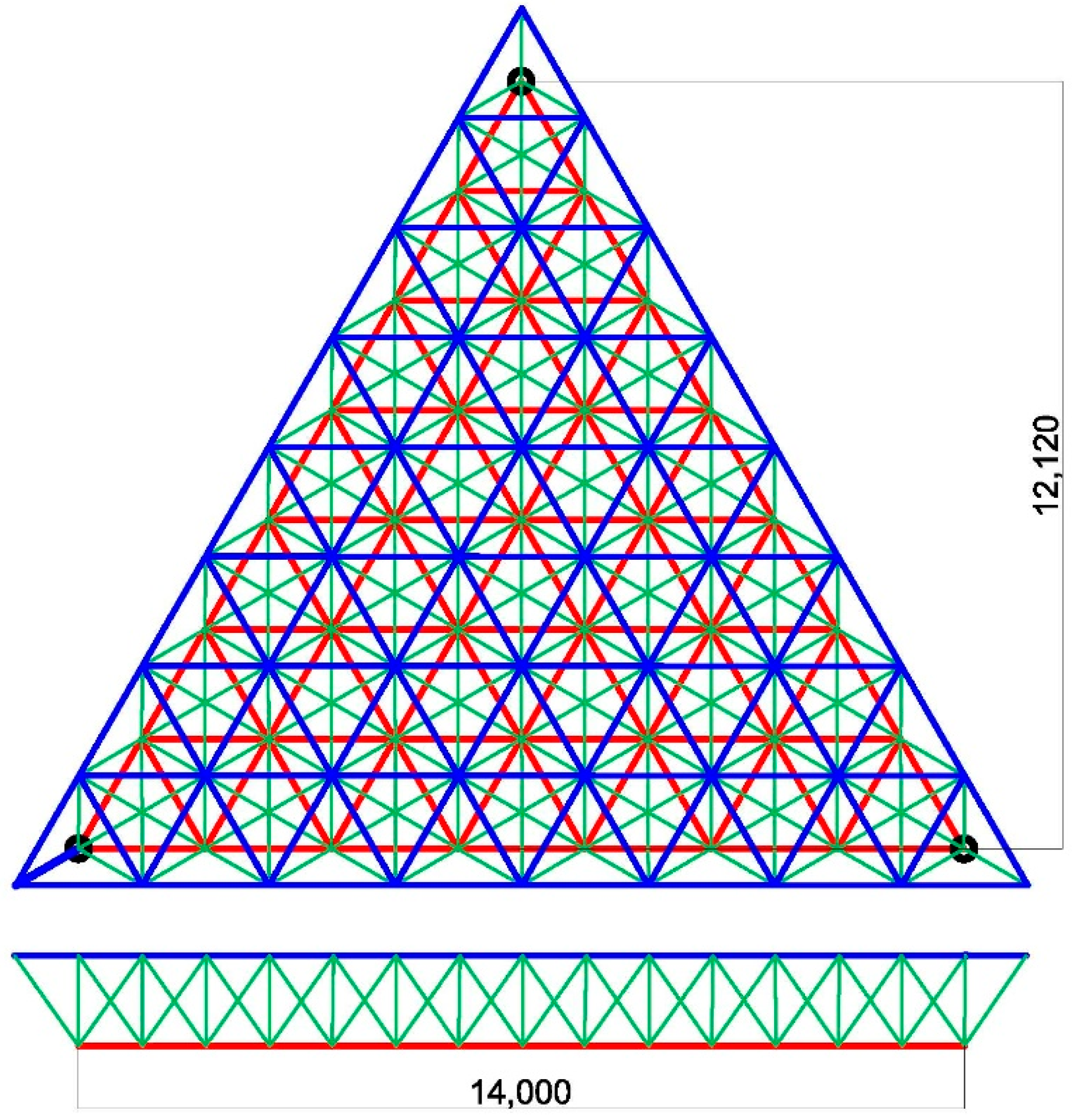
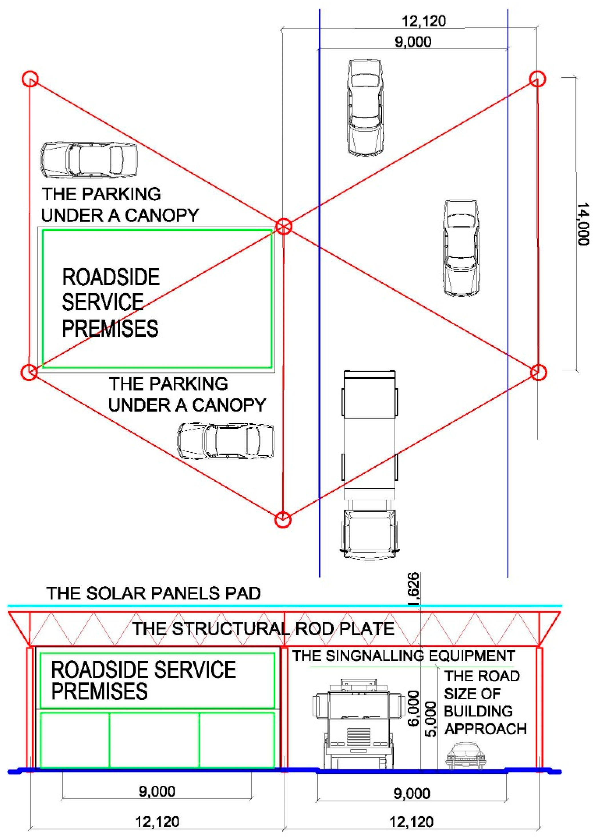
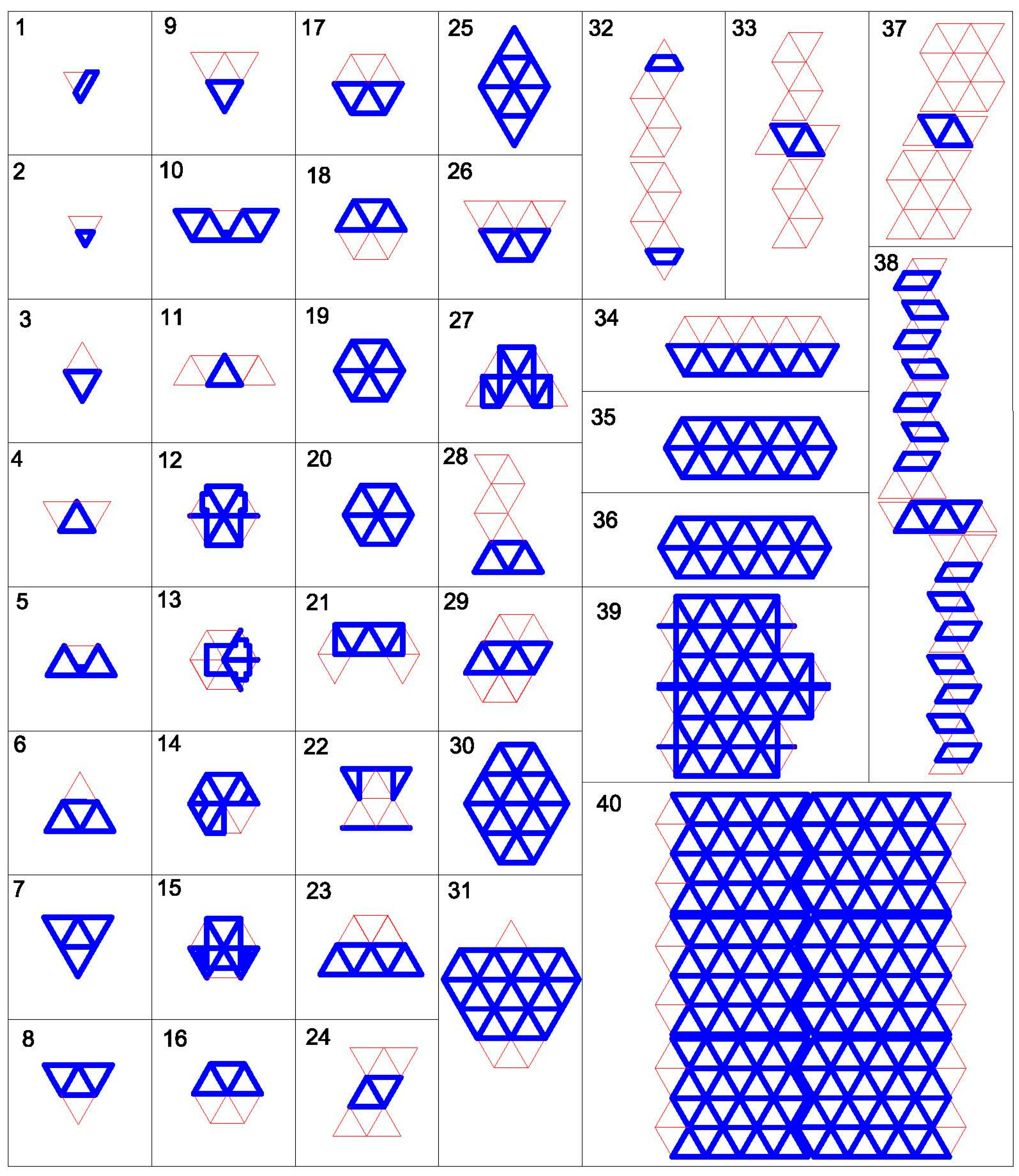
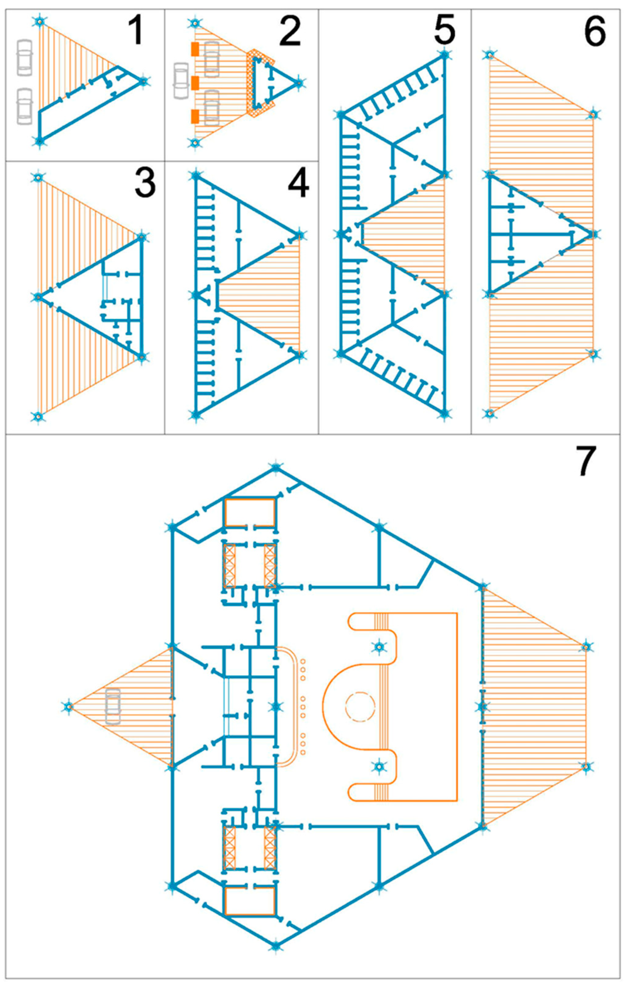
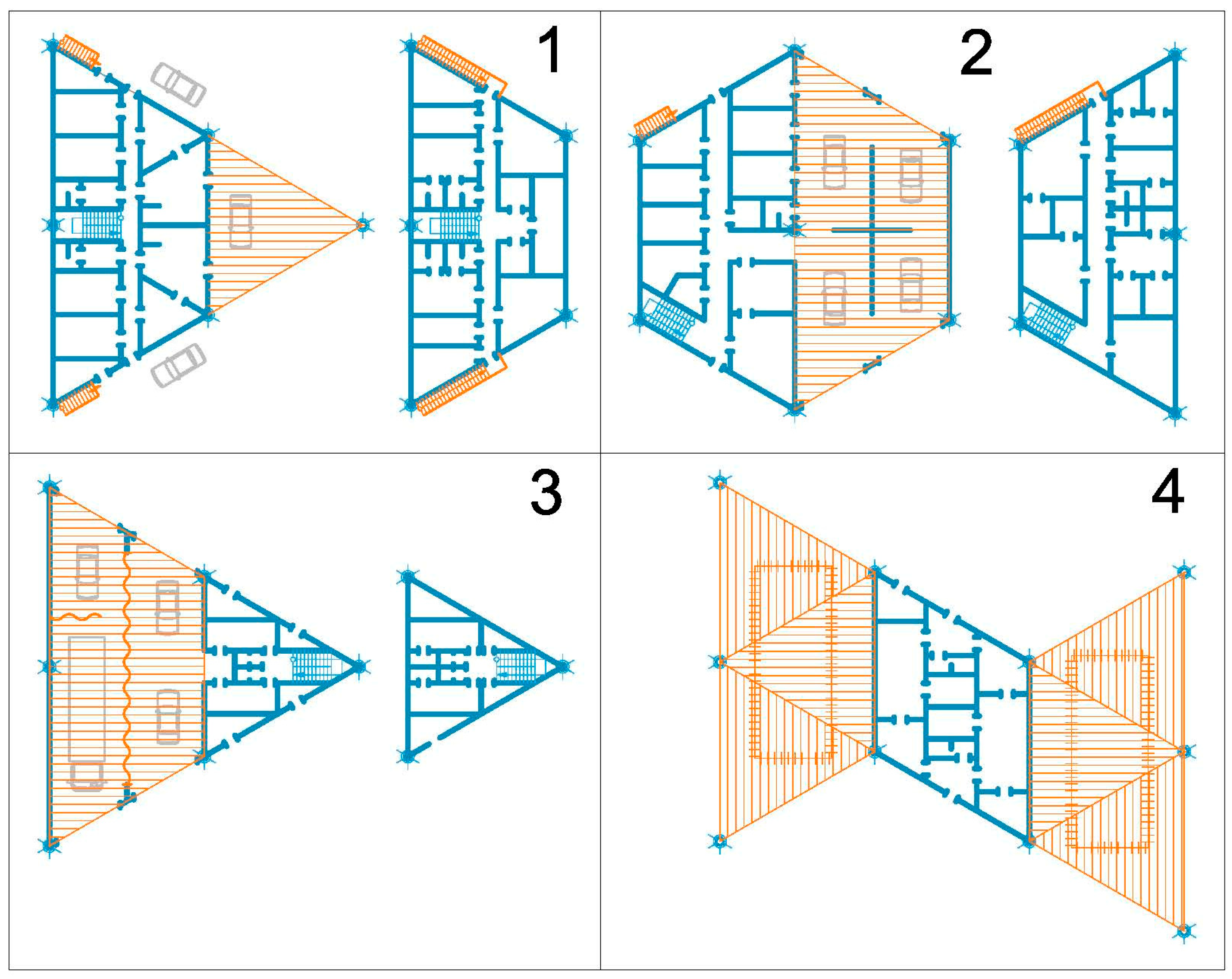
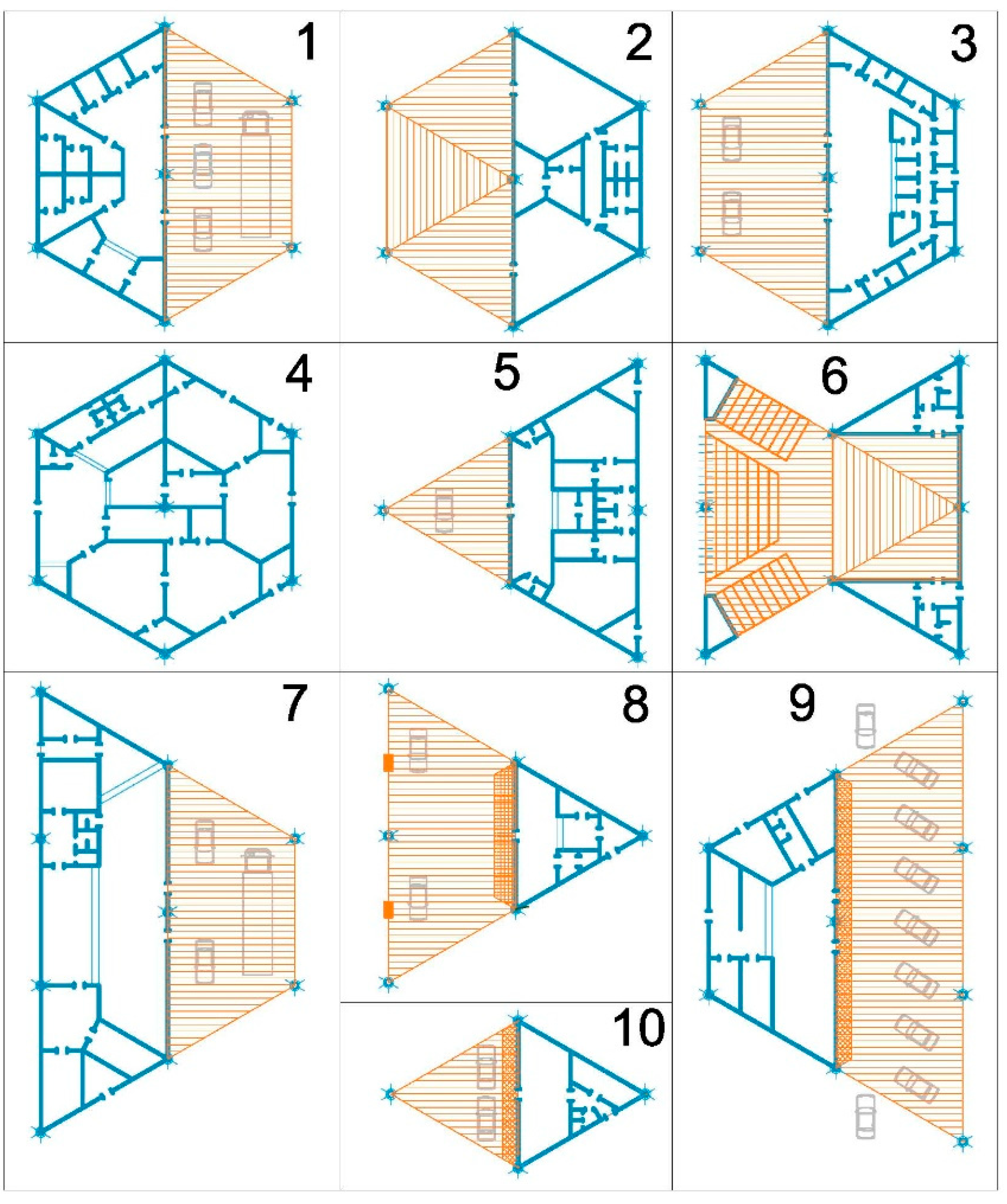
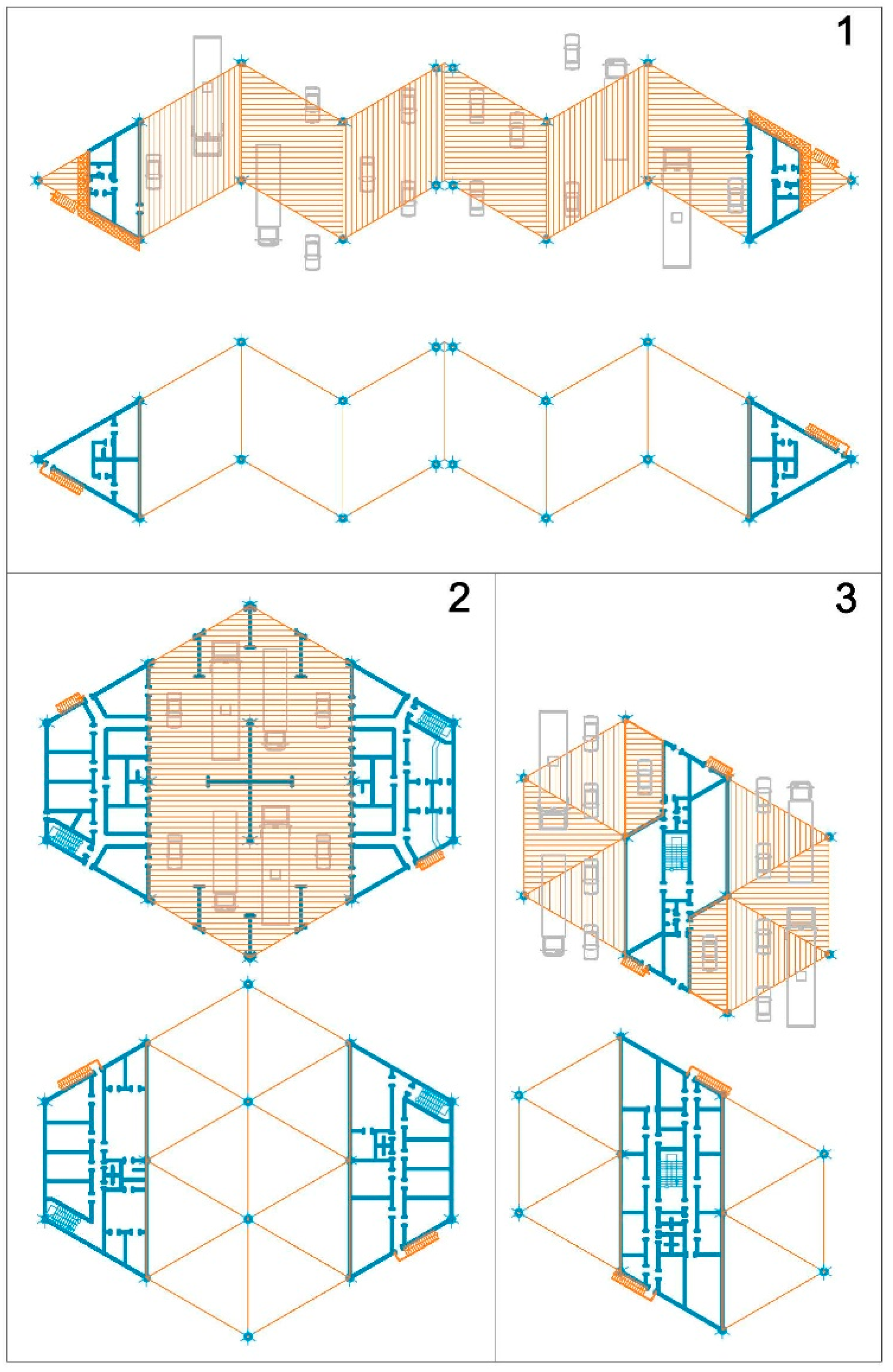
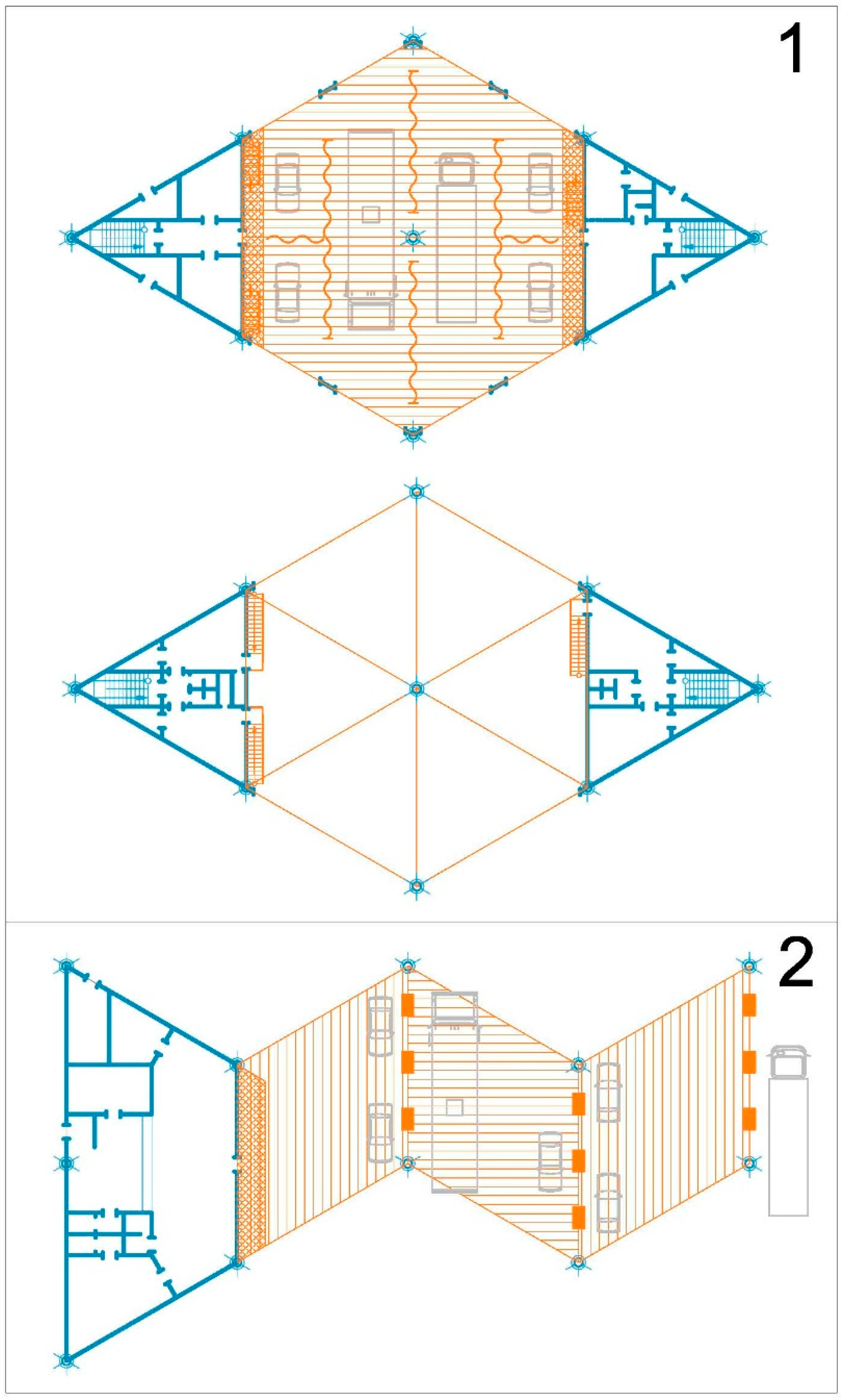
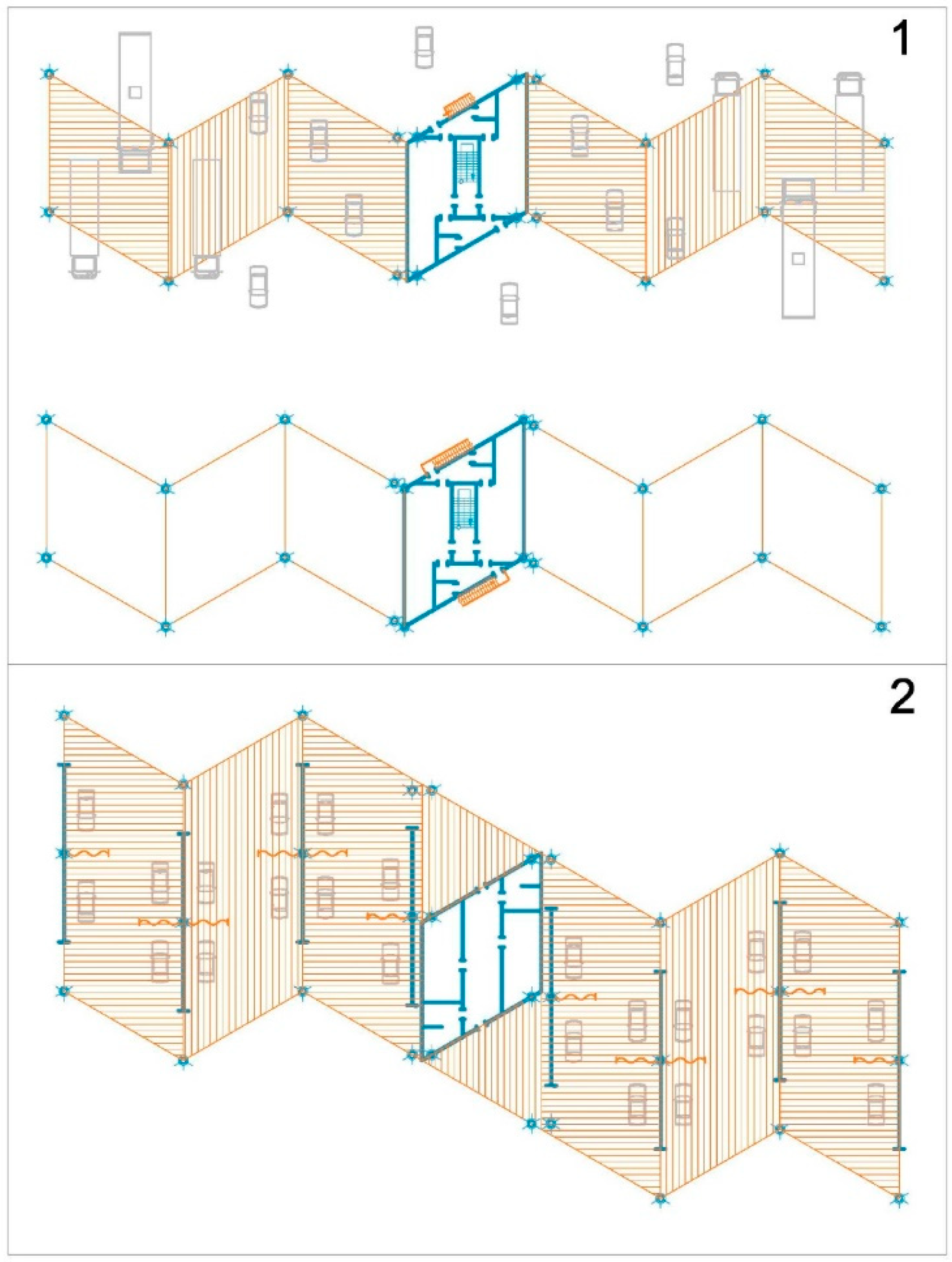
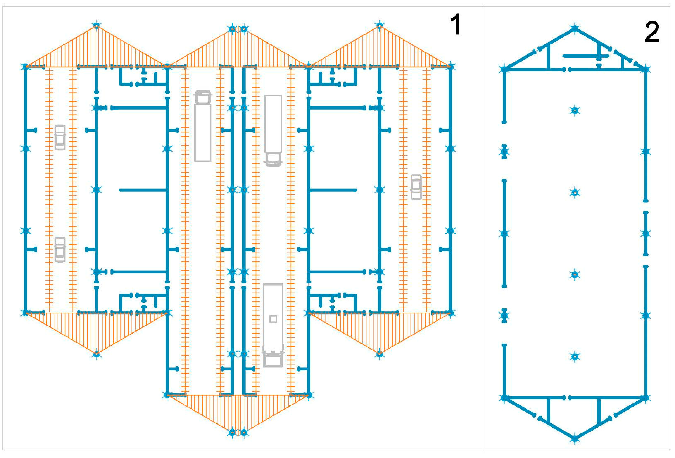
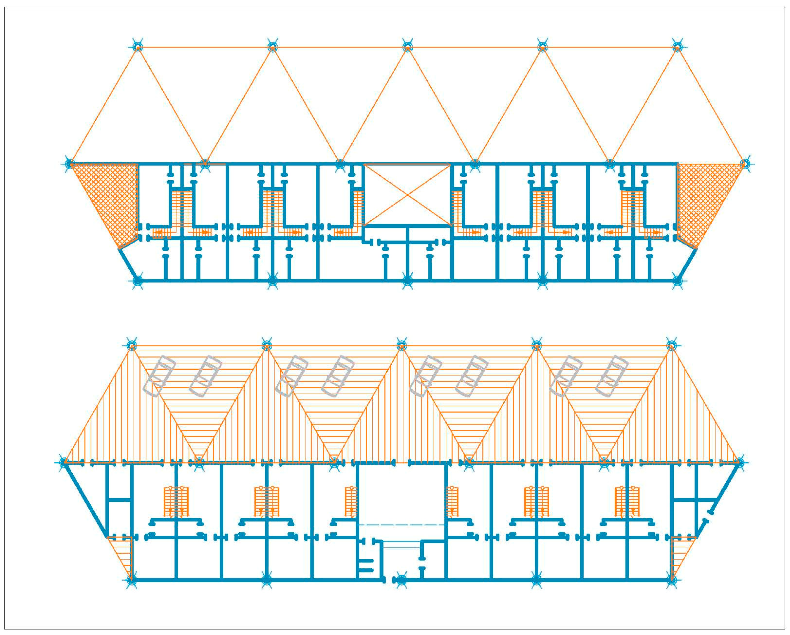
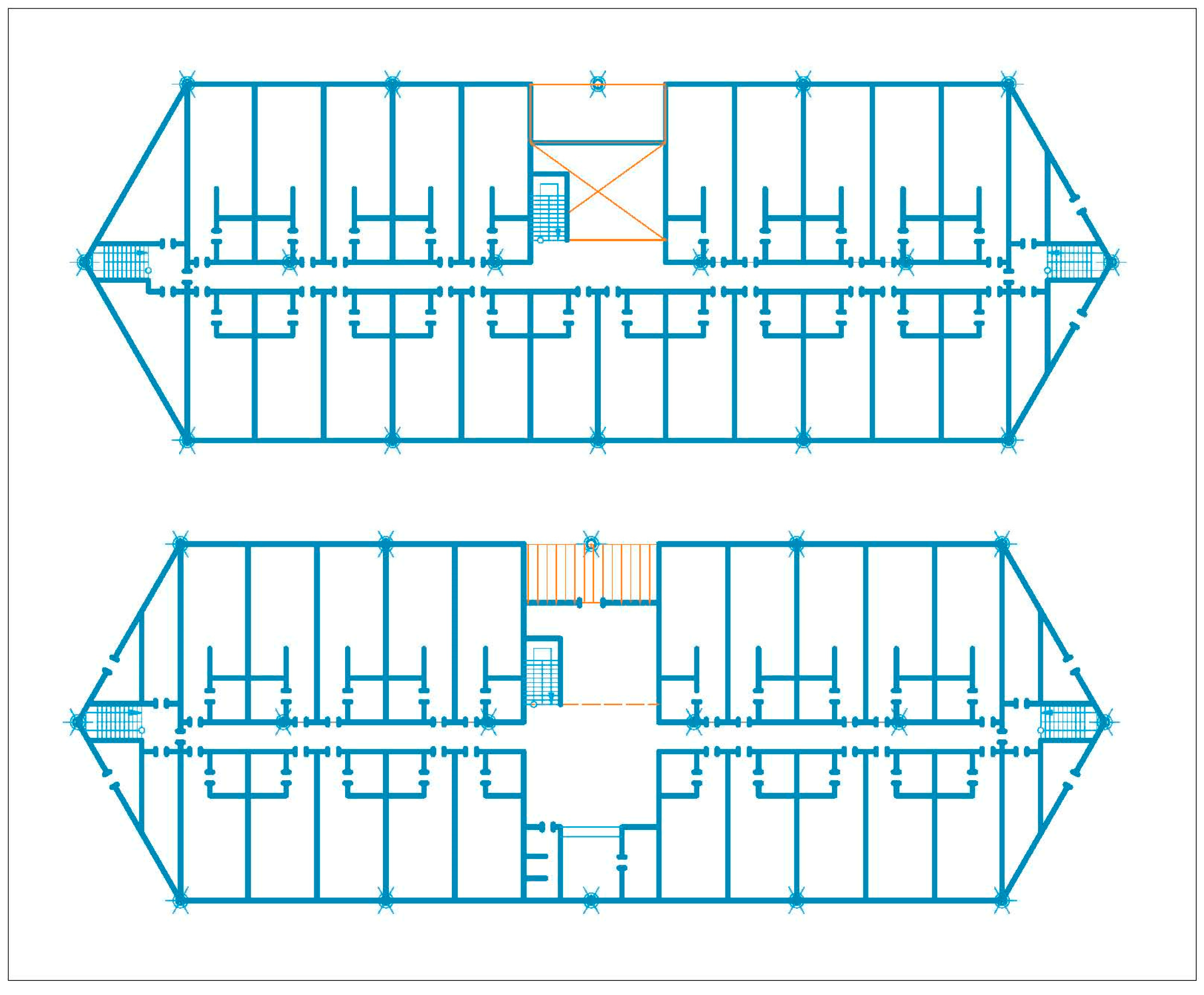
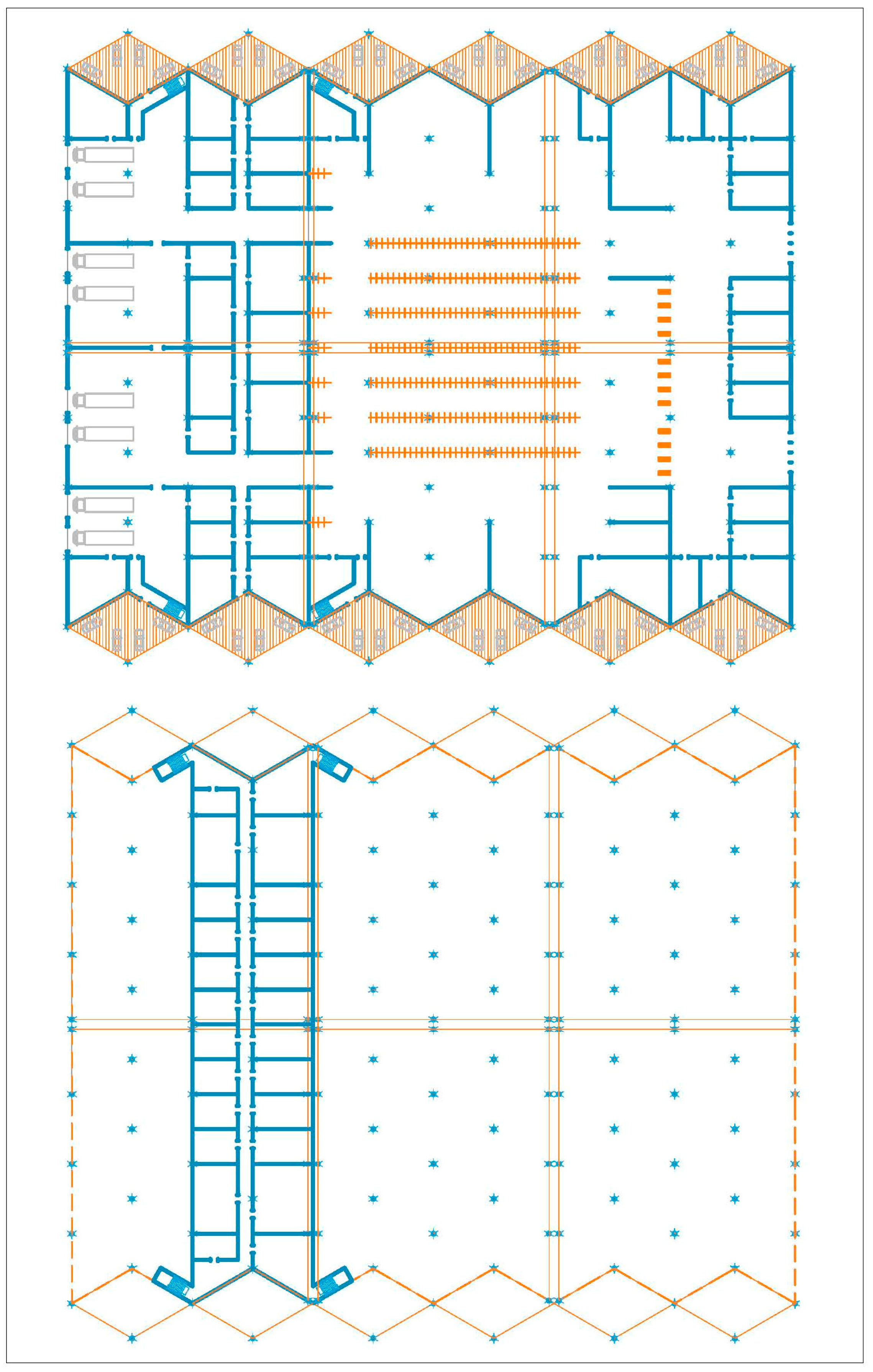
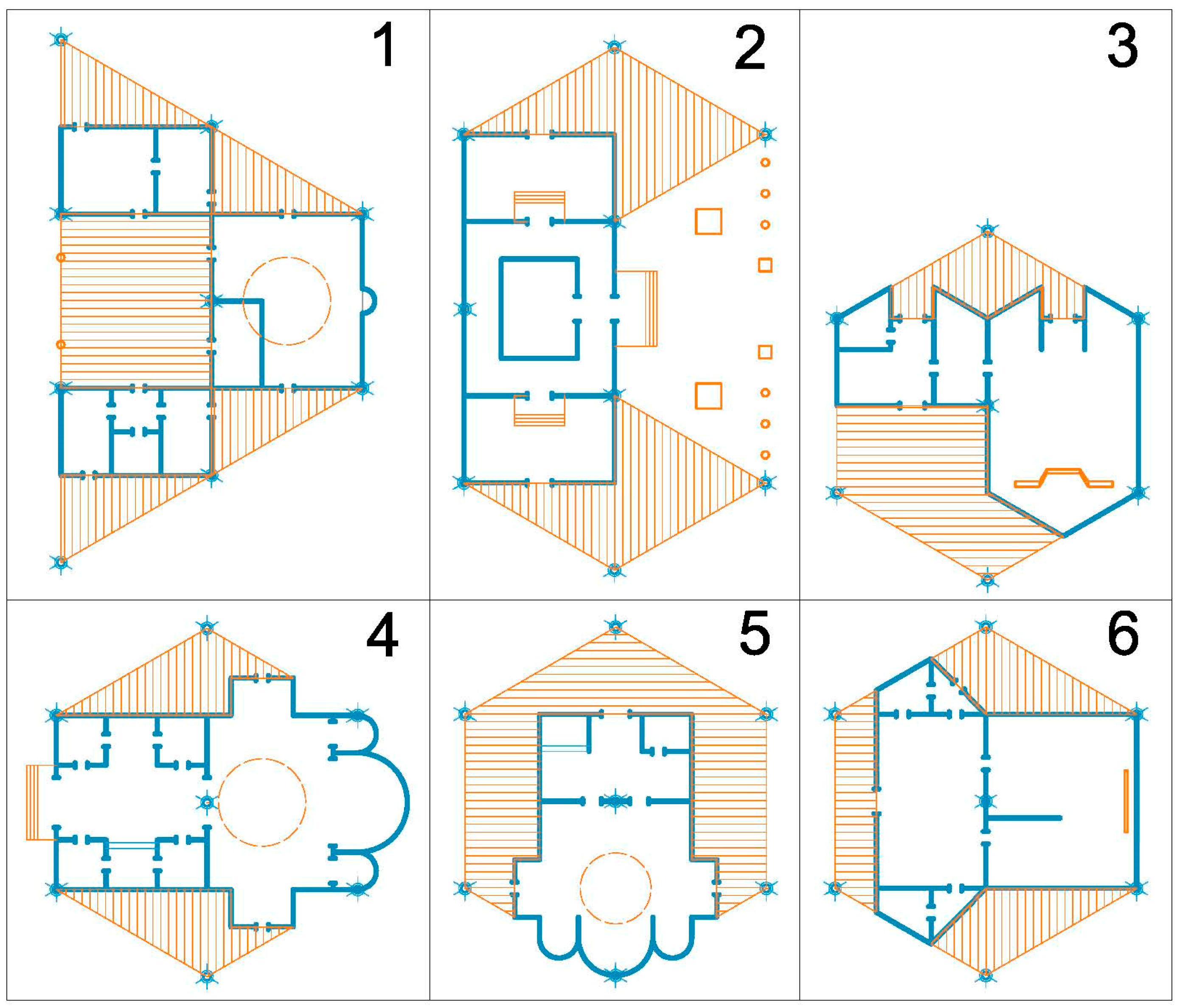
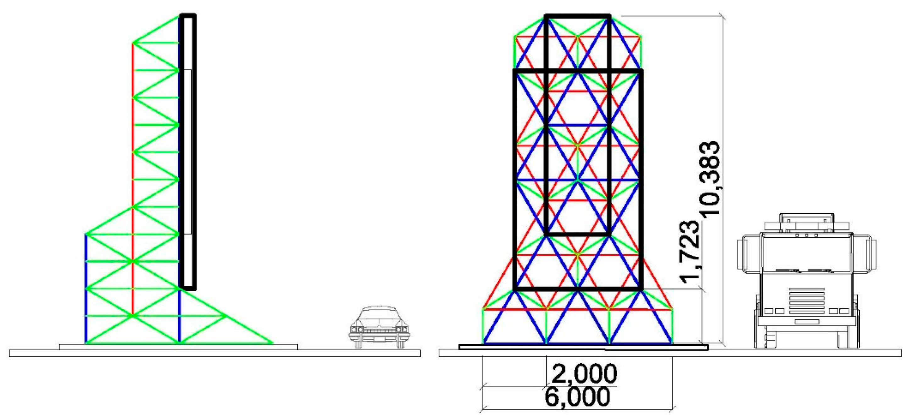


