
Development of Membrane Electrode Assembly with Double-Catalytic Layer for Micro Direct Methanol Fuel Cell


Abstract
:1. Introduction
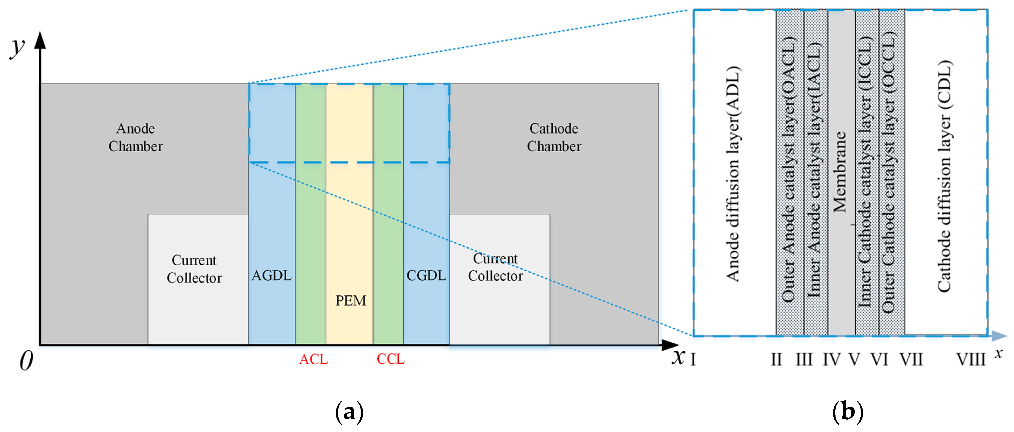
2. Materials and Methods
2.1. Mathematical
2.2. Experimental
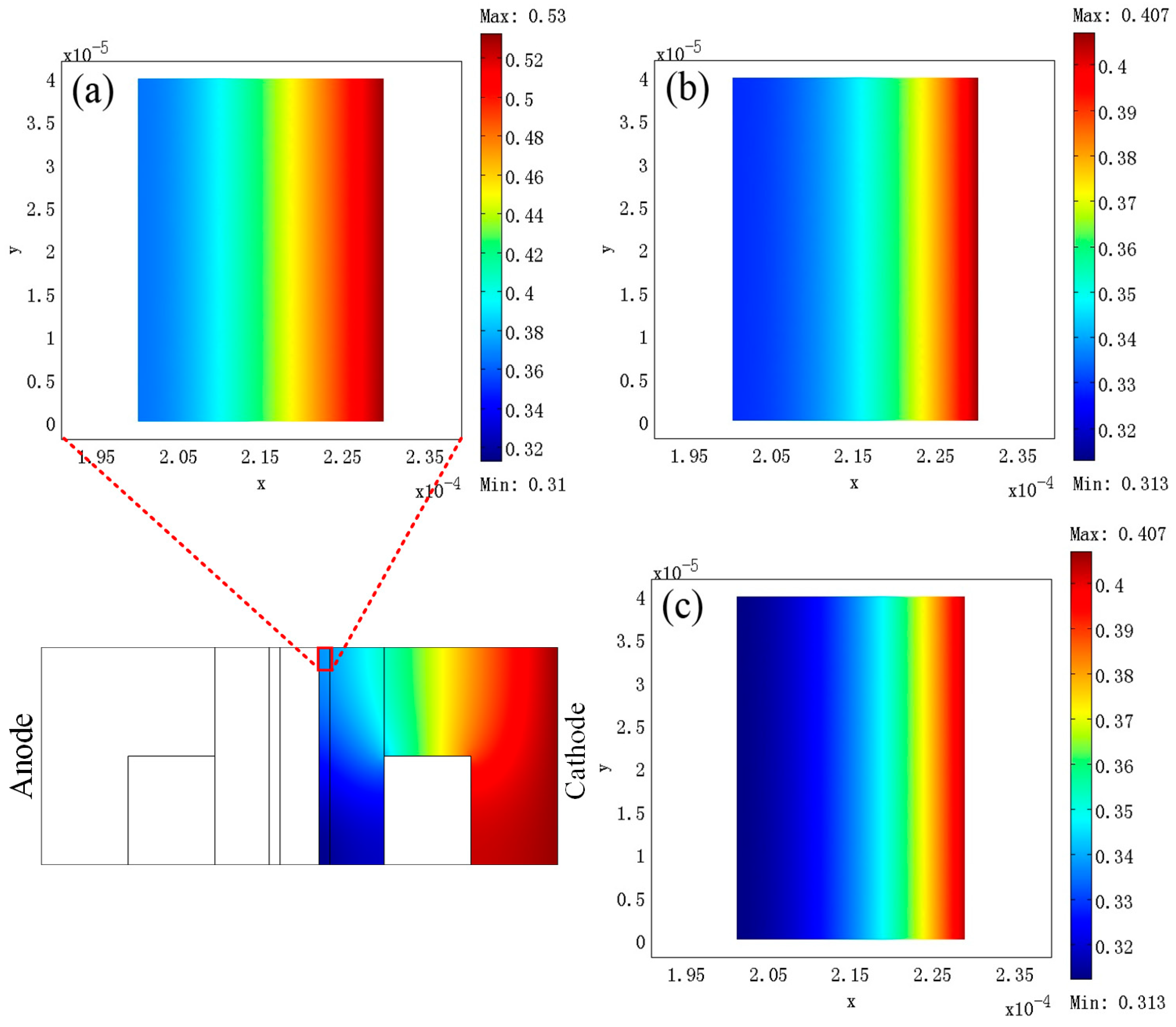
3. Results
4. Discussion
5. Conclusions
Author Contributions
Funding
Data Availability Statement
Acknowledgments
Conflicts of Interest
References
- Li, Y.R.; Li, H.W.; Zhao, Y.; Ji, D.; Guo, P.; Li, G.X.; Zhao, X.H. Insights on the Roles of Nitrogen Configuration in Enhancing the Performance of Electrocatalytic Methanol Oxidation over Pt Nanoparticles. Small 2023, 19, e2303065. [Google Scholar] [CrossRef] [PubMed]
- Zhao, M.L.; Xu, J.F.; Zhao, J.N.; Sun, S.S.; Tang, W.B.; Huang, Q.H.; Yu, N.F.; Wu, Y.P. Incorporation of ultralow manganese dioxide for improving the durability of sulfonated poly (ether ether ketone) membranes in passive direct methanol fuel cell. Polymer 2023, 283, 126204. [Google Scholar] [CrossRef]
- Guo, S.Q.; Yu, S.Y.; Chen, F.; Wang, L.; Guo, M.; Ren, T.L.; Zhang, C.; Li, C.J. Direct methanol fuel cell with enhanced oxygen reduction performance enabled by CoFe alloys embedded into N-doped carbon nanofiber and bamboo-like carbon nanotube. J. Colloid Interface Sci. 2023, 652, 429–439. [Google Scholar] [CrossRef] [PubMed]
- Jia, F.S.; Zhang, Y.J.; Zhang, P.; Zhang, X.T.; Hu, T.P. In situ growth of Ni/Ni3S2-MoO2 nanocrystals on carbon cloth for the enhanced electrocatalytic oxidation of methanol. Appl. Surf. Sci. 2023, 640, 158348. [Google Scholar] [CrossRef]
- Zuo, Y.H.; Sheng, W.C.; Tao, W.Q.; Li, Z. Direct methanol fuel cells system-A review of dual-role electrocatalysts for oxygen reduction and methanol oxidation. J. Mater. Sci. Technol. 2022, 114, 29–41. [Google Scholar] [CrossRef]
- Bonham, D.; Choi, J.Y.; Kishimoto, T.; Ye, S.Y. Integrating PGM-Free Catalysts into Catalyst Layers and Proton Exchange Membrane Fuel Cell Devices. Adv. Mater. 2019, 31, e1804846. [Google Scholar] [CrossRef]
- Yang, L.J.; Shui, J.L.; Du, L.; Shao, Y.Y.; Liu, J.; Dai, L.M.; Hu, Z. Carbon-Based Metal-Free ORR Electrocatalysts for Fuel Cells: Past, Present, and Future. Adv. Mater. 2019, 31, 1804799. [Google Scholar] [CrossRef]
- Zhang, L.; Li, L.; Chen, H.M.; Wei, Z.D. Recent Progress in Precious Metal-Free Carbon-Based Materials towards the Oxygen Reduction Reaction: Activity, Stability, and Anti-Poisoning. Chem. Eur. J. 2020, 26, 3973–3990. [Google Scholar] [CrossRef]
- de Sá, M.H.; Moreira, C.S.; Pinto, A.M.F.R.; Oliveira, V.B. Recent Advances in the Development of Nanocatalysts for Direct Methanol Fuel Cells. Energies 2022, 15, 6335. [Google Scholar] [CrossRef]
- Kotp, A.A.; Abdelwahab, A.; Farghali, A.A.; El Rouby, W.M.A.; Allah, A.E. Evaluating the electrocatalytic activity of flower-like Co-MOF/CNT nanocomposites for methanol oxidation in basic electrolytes. RSC Adv. 2023, 13, 27934–27945. [Google Scholar] [CrossRef]
- Lou, W.H.; Ali, A.; Shen, P.K. Recent development of Au arched Pt nanomaterials as promising electrocatalysts for methanol oxidation reaction. Nano Res. 2022, 15, 18–37. [Google Scholar] [CrossRef]
- Reshetenko, T.V.; Kim, H.T.; Krewer, U.; Kweon, H.J. The effect of the anode loading and method of MEA fabrication on DMFC performance. Fuel Cells 2007, 7, 238–245. [Google Scholar] [CrossRef]
- Reshetenko, T.V.; Kim, H.T.; Kweon, H.J. Cathode structure optimization for air-breathing DMFC by application of pore-forming agents. J. Power Sources 2007, 171, 433–440. [Google Scholar] [CrossRef]
- Wang, G.X.; Sun, G.Q.; Wang, Q.; Wang, S.; Guo, J.S.; Gao, Y.; Xin, Q. Improving the DMFC performance with Ketien Black EC 300J as the additive in the cathode catalyst layer. J. Power Sources 2008, 180, 176–180. [Google Scholar] [CrossRef]
- Wang, G.X.; Sun, G.Q.; Wang, Q.; Wang, S.L.; Sun, H.; Xin, Q. Effect of carbon black additive in Pt black cathode catalyst layer on direct methanol fuel cell performance. Int. J. Hydrogen Energy 2010, 35, 11245–11253. [Google Scholar] [CrossRef]
- Roul, B.; Gorle, D.B.; Raj, G.; Kumar, K.; Kumari, M.; Nanda, K.K.; Krupanidhi, S.B. Solid-state synthesis of Pt/C cathode catalysts for direct methanol fuel cells. J. Mater. Chem. C 2023, 11, 11072–11081. [Google Scholar] [CrossRef]
- Singh, H.; Zhuang, S.Q.; Ingis, B.; Nunna, B.B.; Lee, E.S. Carbon-based catalysts for oxygen reduction reaction: A review on degradation mechanisms. Carbon 2019, 151, 160–174. [Google Scholar] [CrossRef]
- Kaur, A.; Kaur, G.; Singh, P.P.; Kaushal, S. Supported bimetallic nanoparticles as anode catalysts for direct methanol fuel cells: A review. Int. J. Hydrogen Energy 2021, 46, 15820–15849. [Google Scholar] [CrossRef]
- Yuan, W.J.; Hou, C.J.; Wu, J.F.; Zhang, Y.F.; Zhang, X.L. A direct methanol fuel cell with outstanding performance via capillary distillation. Chem. Eng. J. 2023, 470, 143663. [Google Scholar] [CrossRef]
- Alias, M.S.; Kamarudin, S.K.; Zainoodin, A.M.; Masdar, M.S. Active direct methanol fuel cell: An overview. Int. J. Hydrogen Energy 2020, 45, 19620–19641. [Google Scholar] [CrossRef]
- Moura, A.S.; Fajín, J.L.C.; Mandado, M.; Cordeiro, M.N.D.S. Ruthenium-Platinum Catalysts and Direct Methanol Fuel Cells (DMFC): A Review of Theoretical and Experimental Breakthroughs. Catalysts 2017, 7, 47. [Google Scholar] [CrossRef]
- Zhou, W.J.; Zhou, B.; Li, W.Z.; Zhou, Z.H.; Song, S.Q.; Sun, G.Q.; Xin, Q.; Douvartzides, S.; Goula, A.; Tsiakaras, P. Performance comparison of low-temperature direct alcohol fuel cells with different anode catalysts. J. Power Sources 2004, 126, 16–22. [Google Scholar] [CrossRef]
- Tsai, M.C.; Yeh, T.K.; Chen, C.Y.; Tsai, C.H. A catalytic gas diffusion layer for improving the efficiency of a direct methanol fuel cell. Electrochem. Commun. 2007, 9, 2299–2303. [Google Scholar] [CrossRef]
- Chang, Z.X.; Guan, L.; Zhang, J.J.; Zhang, W.Q.; Ma, Q.; Shah, A.; Xing, L.; Su, H.N.; Xu, Q. Construction of gradient catalyst layer anode by incorporating covalent organic framework to improve performance of direct methanol fuel cells. Int. J. Hydrogen Energy 2022, 47, 37013–37024. [Google Scholar] [CrossRef]
- Li, X.; Yao, K.X.; Zhao, F.L.; Yang, X.T.; Li, J.W.; Li, Y.F.; Yuan, Q. Interface-rich Au-doped PdBi alloy nanochains as multifunctional oxygen reduction catalysts boost the power density and durability of a direct methanol fuel cell device. Nano Res. 2022, 15, 6036–6044. [Google Scholar] [CrossRef]
- Wan, N.F. Durability study of direct methanol fuel cell under accelerated stress test. J. Power Sources 2023, 556, 232470. [Google Scholar] [CrossRef]
- Tang, H.L.; Wang, S.L.; Pan, M.; Jiang, S.P.; Ruan, Y.Z. Performance of direct methanol fuel cells prepared by hot-pressed MEA and catalyst-coated membrane (CCM). Electrochim. Acta 2007, 52, 3714–3718. [Google Scholar] [CrossRef]
- Xu, C.; Zhao, T.S.; Yang, W.W. Modeling of water transport through the membrane electrode assembly for direct methanol fuel cells. J. Power Sources 2008, 178, 291–308. [Google Scholar] [CrossRef]
- Yang, W.W.; Zhao, T.S.; He, Y.L. Modelling of coupled electron and mass transport in anisotropic proton-exchange membrane fuel cell electrodes. J. Power Sources 2008, 185, 765–775. [Google Scholar] [CrossRef]
- Yang, W.W.; Zhao, T.S. A transient two-phase mass transport model for liquid feed direct methanol fuel cells. J. Power Sources 2008, 185, 1131–1140. [Google Scholar] [CrossRef]
- Zhou, J.; Cao, J.M.; Zhang, Y.F.; Liu, J.F.; Chen, J.Y.; Li, M.X.; Wang, W.Q.; Liu, X.W. Overcoming undesired fuel crossover: Goals of methanol-resistant modification of polymer electrolyte membranes. Renew. Sustain. Energy Rev. 2021, 138, 110660. [Google Scholar] [CrossRef]
- Zhang, G.; Yang, Z.; Zhang, W.; Wang, Y.X. Nanosized Mo-doped CeO enhances the electrocatalytic properties of the Pt anode catalyst in direct methanol fuel cells. J. Mater. Chem. A 2017, 5, 1481–1487. [Google Scholar] [CrossRef]
- Lu, G.B.; Ning, F.D.; Wei, J.; Li, Y.B.; Bai, C.; Shen, Y.B.; Li, Y.L.; Zhou, X.C. All-solid-state passive direct methanol fuel cells with great orientation stability and high energy density based on solid methanol fuels. J. Power Sources 2020, 450, 227669. [Google Scholar] [CrossRef]
- Wu, H.J.; Yuan, T.; Huang, Q.H.; Zhang, H.F.; Zou, Z.Q.; Zheng, J.W.; Yang, H. Polypyrrole nanowire networks as anodic micro-porous layer for passive direct methanol fuel cells. Electrochim. Acta 2014, 141, 1–5. [Google Scholar] [CrossRef]


| Parameters | Symbols | Value | Unit | Ref. | |
|---|---|---|---|---|---|
| Thickness Porosity Permeability | ADL | δADL, εADL, KADL | 2 × 10⁻⁴, 0.7, 1 × 10⁻¹² | m, -, m2 | [28] |
| OACL | δOACL, εOACL, KOACL | 2 × 10⁻⁵, 0.3, 2 × 10⁻¹⁴ | m, -, m2 | [28] | |
| IACL | δIACL, εIACL, KIACL | 1 × 10⁻⁵, 0.1, 2 × 10⁻¹⁴ | m, -, m2 | [28] | |
| MEM | δMEM, -, KMEM | 1.8 × 10⁻⁴, -, 2 × 10⁻¹⁸ | m, -, m2 | [28] | |
| ICCL | δICCL, εICCL, KICCL | 0.1 × 10⁻⁴, 0.1, 2 × 10⁻¹⁴ | m, -, m2 | [28] | |
| OCCL | δOCCL, εOCCL, KOCCL | 0.2 × 10⁻⁴, 0.3, 2 × 10⁻¹⁴ | m, -, m2 | [28] | |
| CDL | δCDL, εCDL, KCDL | 2 × 10⁻⁴, 0.7, 1 × 10⁻¹² | m, -, m2 | [28] | |
| Diffusivities | Dm | 1.58 × 10⁻⁹e0.02623(T−298) | m2 s−1 | [28] | |
| 1.78 × 10⁻⁵(T/273)1.823 | m2 s−1 | [28] | |||
| Dm,mem | 4.9 × 10⁻¹⁰e[2463(1/333−1/T)] | m2 s−1 | [28] | ||
| Operating temperature | T | 298 | K | - | |
| Anode inlet pressure | 1.01 × 10⁵ | Pa | - | ||
| Cathode inlet pressure | 1.01 × 10⁵ | Pa | - | ||
| Inlet methanol concentration | Cm,in | 2.0 | M | - | |
| Inlet oxygen concentration | 9.35 × 10⁻³ | M | - | ||
| Viscosity of gas phase | μg | 2.03 × 10⁻⁵ | kg m−1 s−1 | [28] | |
| Viscosity of liquid phase | μl | 4.05 × 10⁻⁴ | kg m−1 s−1 | [28] | |
| Electro-osmotic drag coefficients of water and methanol | 2.9e[1029(1/333−1/T)] | - | [29] | ||
| - | [28] | ||||
| Proton conductivity in membrane and catalyst layers | κm κc | 7.3e[1268(1/298−1/T)] 0.1416 | S m−1 S m−1 | [28] [30] | |
| Thermodynamic potential | E0 | 1.21 | V | [28] | |
| Transfer coefficient of anode and cathode | αa αc | 0.5 1.0 | - - | [28] [28] | |
| Anode exchange current density in OACL and IACL | 1.0 × 10⁵ 1.5 × 10⁵ | A m−3 A m−3 | [28] - | ||
| Cathode exchange current density in ICCL and OCCL | 6.97 × 10² 1.05 × 10³ | A m−3 A m−3 | [28] - | ||
| Anode reference concentration | 0.1 | M | [28] | ||
| cathode reference concentration | 3.65 × 10⁻² | M | [28] | ||
| Surface tension | σ | 0.0644 | N m−1 | [28] | |
| Contact resistance | Rcontact | 8 × 10⁻⁵ | Ω m2 | [28] | |
| Ref. | Catalyst Layer Design | Temperature (°C) | Power Density (mW cm−2) | Total Noble Metal Loadings (mg cm−2) |
|---|---|---|---|---|
| This work | Double-catalytic layer | 25 | 25.1 | 2.4 |
| Non-supported Pt | 19.6 | |||
| Pt/C | 18.8 | |||
| [16] | Pt/C | 60 | 82.28 | 3.2 |
| [19] | Pt/C | 25 | 22.3 | 2.4 |
| [32] | Pt-CeMoO/C | 60 | 69.4 | 3.2 |
| [33] | Pt/C | 25 | 17.2 | 3 |
| [34] | Pt/Polypyrrole nanowire | 25 | 34.3 | 5 |
Disclaimer/Publisher’s Note: The statements, opinions and data contained in all publications are solely those of the individual author(s) and contributor(s) and not of MDPI and/or the editor(s). MDPI and/or the editor(s) disclaim responsibility for any injury to people or property resulting from any ideas, methods, instructions or products referred to in the content. |
© 2024 by the authors. Licensee MDPI, Basel, Switzerland. This article is an open access article distributed under the terms and conditions of the Creative Commons Attribution (CC BY) license (https://creativecommons.org/licenses/by/4.0/).
Share and Cite
Zhang, S.; Jiang, Y. Development of Membrane Electrode Assembly with Double-Catalytic Layer for Micro Direct Methanol Fuel Cell. Inventions 2024, 9, 19. https://doi.org/10.3390/inventions9010019
Zhang S, Jiang Y. Development of Membrane Electrode Assembly with Double-Catalytic Layer for Micro Direct Methanol Fuel Cell. Inventions. 2024; 9(1):19. https://doi.org/10.3390/inventions9010019
Chicago/Turabian StyleZhang, Shubin, and Yanfeng Jiang. 2024. "Development of Membrane Electrode Assembly with Double-Catalytic Layer for Micro Direct Methanol Fuel Cell" Inventions 9, no. 1: 19. https://doi.org/10.3390/inventions9010019