Article

Design and Fabrication of an In Situ Short-Fiber Doser for Fused Filament Fabrication 3D Printer: A Novel Method to Manufacture Fiber–Polymer Composite

School of Engineering and Physical Sciences, Heriot-Watt University Malaysia, No 1, Jalan Venna P5/2, Precinct 5, Putrajaya 62200, Malaysia
*
Author to whom correspondence should be addressed.
Inventions 2023, 8(1), 10; https://doi.org/10.3390/inventions8010010
Submission received: 11 November 2022 / Revised: 12 December 2022 / Accepted: 19 December 2022 / Published: 3 January 2023
(This article belongs to the Special Issue Innovations in 3D Printing 2.0)

Abstract

:
Fused filament fabrication (FFF) 3D-printed parts are mostly used as prototypes instead of functional parts because they have a weaker mechanical strength compared to their injection molded counterparts. Various methods including a fiber-reinforced polymer composite were proposed to enhance the properties of FFF 3D-printed parts. A new concept to fabricate a polymer composite via FFF 3D printing is proposed, where fiber is deposited during printing, instead of using a premixed composite filament. In order to investigate the workability of this concept, a new device is needed. Firstly, the design requirements were identified, and a fiber doser that can be mounted on a commercial 3D printer was designed. Prototype testing was conducted to improve the design. The improved fiber doser was able to deposit varied fiber contents during FFF 3D printing. Thermogravimetric analysis (TGA) was used to quantify the fiber contents of the fabricated composites. With this newly designed doser, short glass fiber–polylactic acid (PLA) composites with three different fiber contents (1.02 wt.%, 2.39 wt.%, and 4.98 wt.%) were successfully manufactured. A new technique to manufacture a polymer composite is proven; nevertheless, the mechanical and tribological properties of the newly fabricated composites are under investigation and will be reported in a subsequent article.

1. Introduction

Additive manufacturing (AM) or 3D printing is one of the new technologies with great potential for the design and manufacturing industry. With 3D printing, components with complex geometries can be produced using computer software. The common techniques for printing 3D parts are selective laser sintering (SLS), fused filament fabrication (FFF), also called fused deposition modelling (FDM), stereolithography (SLA), and 3D inkjet printing. The advantages of additive manufacturing are ease of customization of parts, reduced part count, decreased design time, etc. FFF is the most widely used AM technique. However, most FFF 3D-printed polymer products are still used as prototypes rather than functional components. This is due to the lower strength of FFF 3D-printed polymer products in comparison to conventionally manufactured polymer products. The main reasons for the lower strength of 3D-printed FFF parts are the lack of adhesion strength of the intermediate layers and the occurrence of voids between the layers, as the products are printed layer by layer [1]. To solve this problem, three approaches are used: (i) post-processing [2], (ii) adding an additional process, such as chemically melting finishing [1], or (iii) adding reinforcement/s [3,4]. Among the three approaches, the reinforcement method is widely studied. Various forms and materials are used to reinforce 3D-printed products [3,4].
Particles [5], fibers [6,7], and nanofillers such as graphene [8], carbon nanotubes [9], nano clay [10], etc., have been used as reinforcement. Nanomaterials can improve 3D-printed AM materials by modifying their basic material properties [11]. Furthermore, different materials can be added to the polymer matrix to achieve different outcomes such as better strength, better thermal conductivity, better dielectric constant, or even better tribological properties. For example, carbon fibers are added to improve the thermal conductivity of nylon [12]; aluminum and alumina are added to improve the wear resistance and frictional behavior of nylon [13]; and tungsten is added to improve the dielectric constant and impact resistance of polycarbonate [14]. In addition to the types of fibers used, the final properties of composites are also affected by the fiber length and fiber-implementation techniques [15]. Three fabrication techniques based on the timing and location of the embedding of the fibers are commonly used to produce fiber-reinforced thermoplastic composites. The three techniques, namely ‘embedding before the printing process (M1)’, ‘embedding in the nozzle (M2)’, and ‘embedding on the component (M3)’, were summarized in a recent review paper [15]. Goh et al. (2019) reviewed the recent advances in the additive manufacturing of fiber-reinforced polymer composites [4]. The research works based on ‘embedding before the printing process’ or ‘pre-reinforced filament’ are extensive. In general, the reinforcements were mixed with polymer matrix to produce composite filaments before 3D printing, and then these composite filaments were used to print objects. Love et al. investigated 3D-printed parts with their premixed carbon fiber–acrylonitrile butadiene styrene (ABS) filament, and they succeeded in improving the strength of 3D-printed ABS parts [16]. Similar techniques were used to produce short fiber/particle polymer composites, but with different combinations of matrixes and reinforcements [6,7,17]. Meanwhile, continuous fiber-reinforced polymer composites, fabricated by ‘embedding before the printing process’, were produced by a self-developed machine/techniques [18,19].
In addition to pre-reinforced filament, polymer composites formed during printing have also been investigated. Mori et al. [20] investigated embedding long, continuous carbon fibers directly into the printed ABS part after the nozzle (embedding on the component). In their work, two layers of carbon fibers were manually placed on the top and bottom plates of an ABS train and then thermally bonded. Their results showed that thermally bonded carbon fiber-reinforced ABS has a higher strength compared to pure ABS. A similar work was presented by Baumann et al. [21], where long carbon fibers or glass fibers were manually placed on an ABS matrix using three different fiber-implementation methods—direct overpressure, injection needle, and solvents. Their results showed that using solvents was the best method in terms of tensile strength, while the glass-fiber-reinforced method for ABS with solvents and direct overpressure gave the best results in terms of elastic modulus. Franco-Urquiza et al. placed jute fiber fabric onto 3D-printed polylactic acid (PLA) specimens during 3D printing to produce a PLA/jute fiber composite [22]. Five different fiber treatment strategies were investigated, and they found that PLA has a better tensile modulus and higher plastic deformation than all PLA/jute fiber composites. While Mori et al., Baumann et al., and Franco-Urquiza et al. applied the reinforced fibers manually, Dickson et al. [23] used a commercially available Markforged Markone 3D printer to produce carbon, glass, and Kevlar fiber-reinforced nylon composites. They found that the fiber-reinforced nylon composites are five–six times better than pure nylon in terms of tensile and flexural strengths. In addition, carbon fibers are better than glass fibers and Kevlar fibers in terms of tensile and flexural strengths. A similar technique was used by Caminero et al., where they investigated the process parameters for the optimal interlaminar shear strength of continuous fiber-reinforced thermoplastic composites, and the results showed that carbon fiber is the best reinforcement among carbon fiber, glass fiber, and Kevlar fiber [24]. Van de Werken et al. used finite element analysis to investigate the mechanism and failure modes of continuous fiber-reinforced 3D-printed parts, but no study on in situ reinforcement has been completed [25]. The fiber content in a fiber composite is an important factor for determining the properties of the composite. Various methods such as the digestion method (ASTM D3171-22) [26], the microscopy method [27], and the thermogravimetric analysis method [28,29,30] have been used to determine fiber content. The thermal gravimetric analysis (TGA) method has been successfully used by Yee et al. [31], Moon et al. [28], Buecheler et al., and Grund et al. [29,30] to determine the glass fiber or carbon fiber content of fiber-reinforced polymer composites.
Although studies have showed the addition of reinforcements can improve the mechanical properties of 3D-printed polymers, the mechanical properties of 3D-printed polymers are still weaker compared to polymers produced by traditional molding methods [10]. Existing 3D-printed FFF short fiber composites were reinforced before printing, though the reinforcement was missing in the weakest region, i.e., the area between the layers. Therefore, 3D-printed composites made from polymer filament reinforced with particles/fibers/nanocomposites (pre-reinforced filament) may not be the best solution to address this problem.
Previous research [20,21,22] has shown the potential of an in situ fiber–polymer composite, but the composites were fabricated manually. Furthermore, no previous work on an in situ short fiber–polymer composite has been reported. In situ reinforcement during printing is a possible method to further improve the mechanical properties of 3D-printed parts. A comparison of 3D-printed parts by a neat polymer, a premixed composite filament, and the proposed in situ short fiber reinforcement is presented in Figure 1. The short fiber is placed in between the layers and also fills the voids. The in situ short fiber reinforcement method (ISSFRM) has the potential to address the interlayer adhesion and voids problem mentioned earlier. The formation of voids and the actual size of theses voids in the composite depend on various factors such as the type of fillers, printing speed, printing temperature, bed temperature, layer height, raster width, infill pattern, infill density, etc. [32]. The percentage of voids in an FFF 3D-printed part generally ranges from 4% to 18.5% [15]. To explore the potential of in situ short fiber reinforcement in FFF 3D printing, and to discover the best combination of polymer matrix/fiber, an automated technique to produce an in situ short fiber–polymer composite is needed. This study designed, fabricated, and tested a fiber doser that can apply short fibers to the deposited material/road during FFF 3D printing.

2. Design and Development of Fiber Doser

2.1. Engineering Requirements and Design Specification

Commercial FFF 3D printers are equipped with one or two nozzles that can apply building and support materials. To apply short fiber reinforcements to the deposited material/molten road during FFF 3D printing, an additional doser that can be added to a commercial FFF printer is needed. There are several design specifications that need to be met. First, the fiber doser should be able to extrude short fibers at a constant rate. Next, the deposition rate of the fibers should be adjustable. Moreover, the fiber doser should be able to be mounted and de-mounted on a standard Cartesian FFF 3D printer, so that the doser can be removed when it is not needed. The doser should be able to move along the original nozzle of the FFF 3D printer. Furthermore, the size and mass of the additional doser must not affect or impinge the original 3D printer’s operation. Finally, the position and angle of the doser must be adjustable.

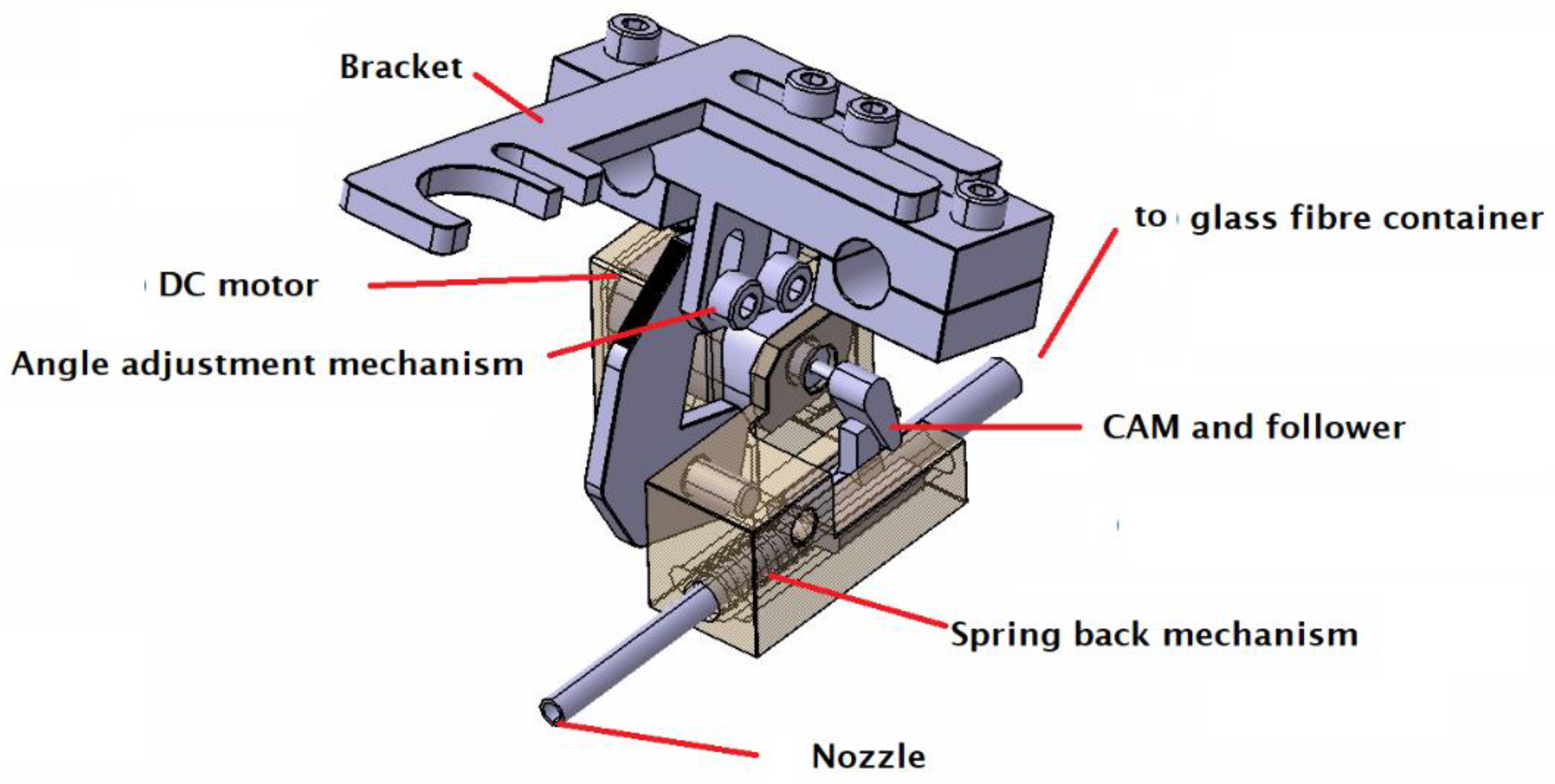
2.2. Design of Fiber Doser

Several design mechanisms such as vibration and gravity effect were considered in preliminary works [33], and a new mechanism using a motor to shake a fiber container was selected for this current work. A computer-aided design (CAD) of the final fiber doser design is shown in Figure 2. The design consists of a nozzle, a container for reinforcement, a springback mechanism, a DC motor, a cam, a follower, an angle-adjustment mechanism, brackets, and an Arduino-based speed controller (Figure 3). To enable a 3D-printed fiber-reinforced polymer composite, the fiber doser is first mounted on a commercially available 3D printer via a fixture/bracket. Reinforcement materials such as fibers or particles are loaded into the container. As soon as the DC motor is switched on, the CAM and driver mechanism convert the rotary motion into a vibration and apply the reinforcement. The application rate of the reinforcement is proportional to the rotation speed of the DC motor, and the rotation speed is controlled by a rotary potentiometer. The motor speed is then shown on an LCD display. The actual fiber content of the composite produced is then determined by thermogravimetric analysis.

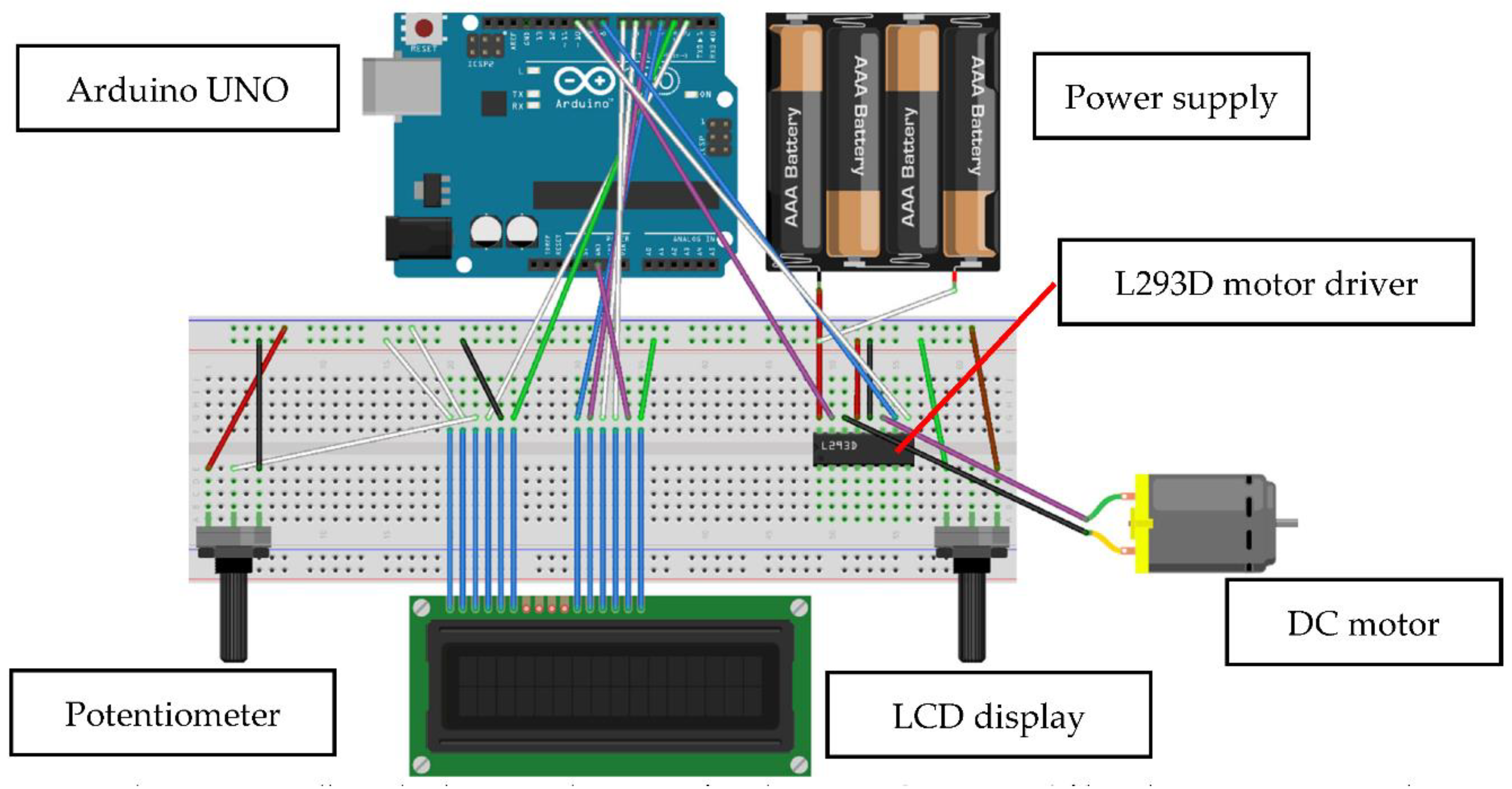
2.3. Prototyping and Testing

Several iterations of prototyping and testing were conducted to refine the design. A prototype of the fiber doser was fabricated by using an FFF 3D printer/PLA material and then mounting on a 3D printer (Forcemaker S220), as shown in Figure 4. FFF 3D printing with the addition of glass fibers between the printing layers was conducted to test the concept. The dimension of the fiber doser, angle of deposition, and driver mechanism were refined and optimized after several iterations. The design of the fiber doser was then finalized based on the prototype tests.

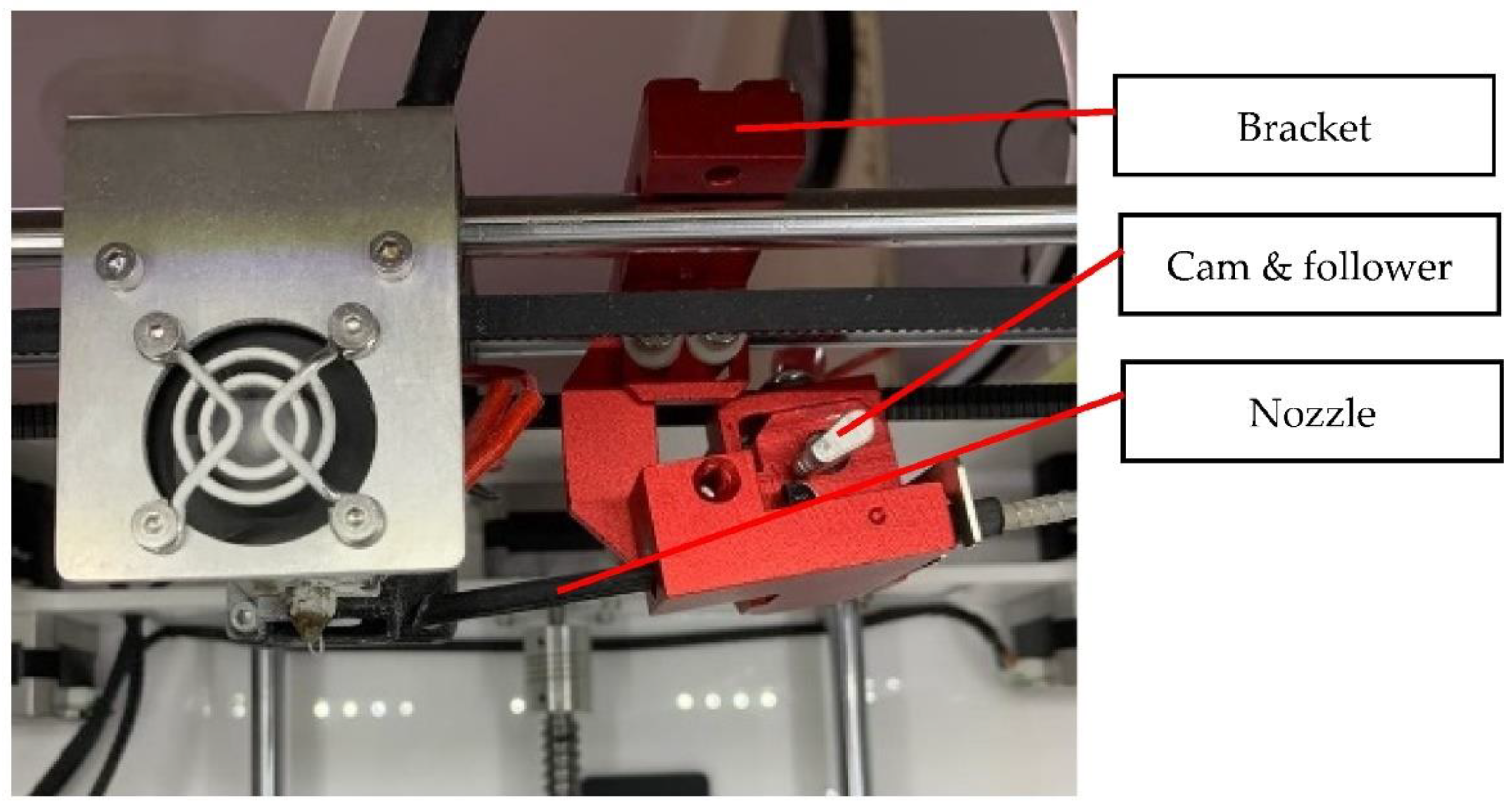
2.4. Commisioning of Fiber Doser

Based on the results from prototype tests, an actual fiber doser was then manufactured with an aluminum alloy. The completed fiber doser was mounted on a Forcemaker S220 3D printer (as shown in Figure 5) to produce an in-situ fiber-reinforced composite. A schematic diagram of the original nozzle and doser is shown in Figure 6, where polymer is deposited by the nozzle, and reinforcement material such as glass fiber is deposited by the additional doser onto the printed polymer layers to form the composite.

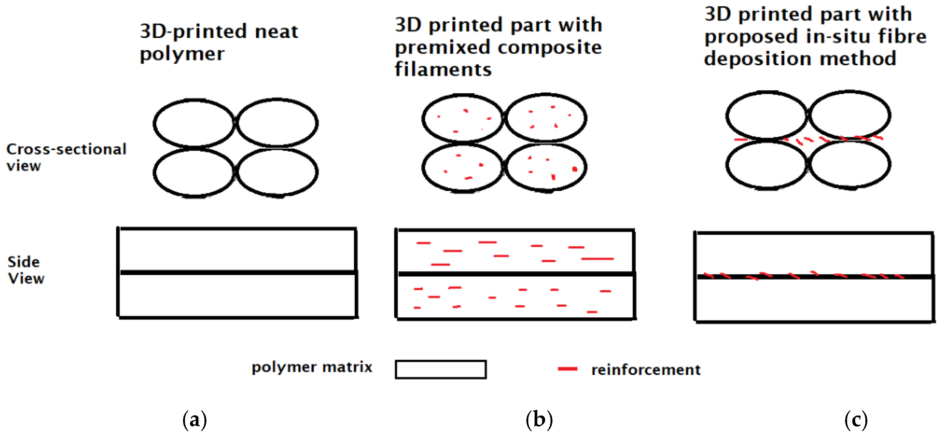
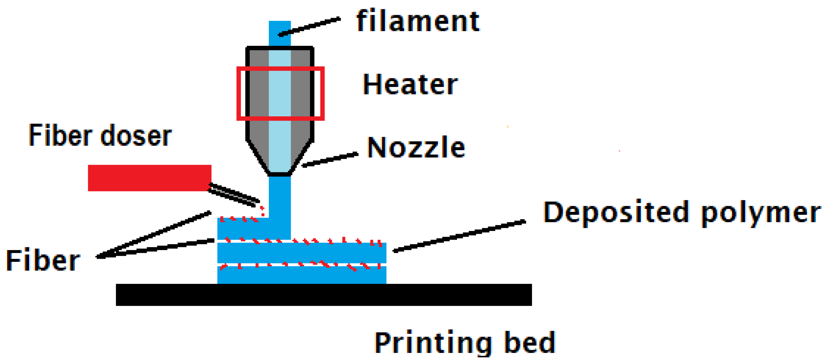
2.5. Fabrication of In Situ 3D-Printed Polymer Composite

Forcemaker’s PLA filament with a diameter of 1.75 mm was used as the matrix, and glass fiber powder was used as the reinforcement. The FFF 3D printing was performed with a nozzle diameter of 0.4 mm, a printing speed of 60 mm/min, a layer thickness of 0.2 mm, a fill density of 100%, and a deposition direction of the fill pattern for the different layers alternating between 45° and 135°. Table 1 summarizes the standard printing parameters used in this study. Molten PLA was deposited on the printed bed or printed parts by the original nozzle, and then the glass fibers were dosed on the molten PLA by the additional dosing unit, as shown in Figure 6. Short glass-fiber-reinforced PLA (GF-PLA) specimens with different fiber contents were produced at different fiber deposition rates of 200, 235, and 250 rpm. The specification of the glass fiber used in the current work (MEF-13-100, Shenzhen Yataida High-Tech Co., Ltd. Shenzhen, China) is shown in Table 2. Samples of the neat PLA and GF-PLA composites are shown in Figure 7. Glass fibers were sandwiched between the PLA layers in the GF-PLA composite.

2.6. Fiber-Content Measurement Method and Inspection

The cross-sectional surface of both PLA and GF-PLA were inspected under SEM (LEO 1455VP) and an extension with energy-dispersive X-ray spectroscopy (EDX) operated at 4.51 kV in order to investigate element composition. The TGA method was chosen to measure the fiber content of the reinforced polymer, although digestion is the standard method proposed by ASTM because the TGA method requires less material and time compared to the digestion method. The residual weight of the composite samples was compared with the residual of the pure matrix sample. The different amount of residual is then considered as the amount of reinforcement. This is because the degradation point temperature of the reinforcement is different from that of the matrix.
In the current work, the weight loss tests of GF, PLA, and three different GF-PLA composites were performed using a thermogravimetric analyzer (METTLER TOLEDO TGA2, Mettler Toledo, Columbus, OH, USA). Pyrolysis was conducted by flowing inert gas (Nitrogen, 50 mL/min) to avoid any potential thermal effects. The data of the residual mass of the GF-PLA samples were compared with the residual mass of the pure PLA sample. The difference in masses was considered as the glass fiber content. All samples were obtained from the middle of the GF-PLA or neat PLA tensile samples. TGA samples were taken at the center of the post-tensile dog-bone-shaped samples. The fractured surface was filed using a mechanical file, and the powder collected was used for TGA. The samples weighed approximately 7–10 mg each, and six replicates were conducted for each composite. The heating program developed for this analysis started with a heating rate of 10 °C min−1 from room temperature to 600 °C, which was then held at 600 °C for 15 min. This heating program was developed based on a preliminary TGA test on pure PLA samples that burned completely.

3. Results and Discussion

Figure 8 showed the energy dispersive analysis (EDX) results of the 3D-printed PLA and GF-PLA. In neat PLA, only the Carbon and Oxygen elements were observed, which are the basic building elements of PLA. In the GF-PLA composites, additional elements such as Silica, Aluminum, and Calcium were observed. Silica and metal oxides are the basic building elements of glass fibers [34]. The elements observed for the neat PLA and GF-PLA composite are in agreement with Adrian et al. [35] and Arife et al. [34]. As such, EDX analysis confirms the presence of glass fiber in the 3D-printed part of a CF-PLA composite.
The degradation behavior of the neat PLA, neat glass fiber, and three PLA-GF composites, A, B, and C, is shown in Figure 9. Two major stages of degradation were observed for the neat PLA, as the neat PLA began to degrade at about 230 °C and ended at about 340 °C during the first stage; this was followed by the second stage with a slower degradation rate from 340 °C to 470 °C. The PLA is considered completely burnt off at 600 °C, with a residual of 0.000 mg. Next, Figure 9 also confirms that the neat glass fiber has not completely burnt off at 600 °C, as glass fiber has a melting temperature of 1135 °C. For the GF-PLA composite A shown in Figure 9, the PLA started to decompose at 260 °C and achieved a constant weight value around 490 °C. Similar trends were observed for GF-PLA B and GF-PLA C. For GF-PLA B, two stages of degradation were detected too, as the first stage started at about 260 °C, and the second stage started from 360 °C. CF-PLA C showed a similar behavior, but the second stage started at a lower temperature (~320 °C). The mean, standard deviation, and relative standard deviation of the mass residue for the six repetitive tests of the GF-PLA composites, collected from TGA, were calculated. Table 3 represent the mass percentage of the fiber volume fraction for each GF-PLA fabricated with different motor speeds.
The contents of glass fiber, α G F , in composites were estimated according to
α G F = [ ( R c R N ) / ( 100 R N ) ] × 100
where Rc is the residue of composite, and RN is the residual of the neat polymer [28,36] (for this study, RN = 0.000 mg, from the results of TGA).
Hence, the fiber contents for GF-PLA composites A, B, and C were found to be 1.02%, 2.39%, and 4.98%, respectively.
From the thermogravimetric analysis, it was proven that the newly designed fiber doser mounted on a commercial 3D printer is able to produce short glass-fiber-reinforced PLA composites with controllable fiber contents.

4. Future Works

A new method to 3D print fiber–polymer composites via an ‘in situ fiber deposition method’ was proposed and verified. Mechanical properties such as the tensile and flexural behaviors of the new composites are under investigation. The roles of fiber in the composite fabricated through the ‘in situ fiber deposition method’ have to be identified. Microscopy and analysis of the cross section of the composites have to be conducted.
Next, printing parameters such as the printing temperature and layer thickness, together with the deposition rate of reinforcement, have to be optimized for the mechanical properties.
Finally, while PLA and glass fiber were selected as the matrix and reinforcement, respectively, in the current study to prove the concept, this technique can be extended to different combinations of matrix–reinforcement such as natural fiber–PLA, carbon fiber–PLA, glass fiber–ABS, etc. The potential of fiber-reinforced polymer composites fabricated via the ‘in situ fiber deposition method’ needs to be further investigated.

5. Conclusions

In this paper, a new method for 3D printing polymer composites was proposed. A device, a fiber doser, was designed according to the design requirements, fabricated, and tested. The device was mounted on a commercial 3D printer and successfully produced three glass-fiber-reinforced PLA composites with different weight percentages: 1.02 wt.%, 2.39 wt.%, and 4.98 wt.% (GF-PLA composites A, B, and C). The deposition rate of the doser was controlled with a rotary potentiometer, and the weight percentages of the glass fibers were determined using TGA. With this newly designed mechanism, a new fiber–polymer composite, where fiber is deposited between the layers during FFF 3D printing, can be fabricated. EDX was used to confirm the elements of the composites, and TGA was used to estimate the content of the glass fiber in the composites. The mechanical and tribological properties of 3D-printed glass-fiber-reinforced PLA and 3D-printed PLA are still being investigated. In the current work, PLA and glass fiber were selected as the matrix and reinforcement material, respectively, to prove the new fabrication concept. The new composite-fabrication technique can be applied to other matrix and fiber materials/lengths to explore the full potential of this new proposed technique.

Author Contributions

Conceptualization, T.C.Y.; methodology, K.I.I., S.R. and T.C.Y.; design, K.I.I.; testing, K.I.I.; investigation, K.I.I., S.R. and T.C.Y.; writing—original draft preparation, K.I.I. and T.C.Y.; writing—review and editing, S.R. and T.C.Y.; supervision, S.R. and T.C.Y.; project administration, T.C.Y.; funding acquisition, T.C.Y. All authors have read and agreed to the published version of the manuscript.

Funding

This work was funded by the Malaysia Ministry of Higher Education (MOHE), under Fundamental Research Grant Scheme (FRGS) grant no. FRGS/1/2019/TK03/HWUM/02/01.

Data Availability Statement

Not applicable.

Acknowledgments

The authors thank Marcus Chay and the engineering team from Nazca Scientific Sdn. Bhd. for their technical support. K.I.I. would like to thank Malaysia Ministry of Higher Education (MOHE) and Heriot-Watt University Malaysia for the financial support. T.C.Y. would like to thank the funder of this project.

Conflicts of Interest

The authors declare no conflict of interest.

References

  1. Takagishi, K.; Umezu, S. Development of the Improving Process for the 3D Printed Structure. Sci. Rep. 2017, 7, 39852. [Google Scholar] [CrossRef] [PubMed] [Green Version]
  2. Lluch-Cerezo, J.; Benavente, R.; Meseguer, M.D.; García-Manrique, J.A. Effect of a Powder Mould in the Post-Process Thermal Treatment of ABS Parts Manufactured with FDM Technology. Polymers 2021, 13, 2422. [Google Scholar] [CrossRef] [PubMed]
  3. Hofstätter, T.; Pedersen, D.B.; Tosello, G.; Hansen, H.N. State-of-the-Art of Fiber-Reinforced Polymers in Additive Manufacturing Technologies. J. Reinf. Plast. Compos. 2017, 36, 1061–1073. [Google Scholar] [CrossRef] [Green Version]
  4. Goh, G.D.; Yap, Y.L.; Agarwala, S.; Yeong, W.Y. Recent Progress in Additive Manufacturing of Fiber Reinforced Polymer Composite. Adv. Mater. Technol. 2019, 4, 1800271. [Google Scholar] [CrossRef] [Green Version]
  5. Nikzad, M.; Masood, S.H.; Sbarski, I. Thermo-Mechanical Properties of a Highly Filled Polymeric Composites for Fused Deposition Modeling. Mater. Des. 2011, 32, 3448–3456. [Google Scholar] [CrossRef]
  6. Ning, F.; Cong, W.; Hu, Y.; Wang, H. Additive Manufacturing of Carbon Fiber-Reinforced Plastic Composites Using Fused Deposition Modeling: Effects of Process Parameters on Tensile Properties. J. Compos. Mater. 2017, 51, 451–462. [Google Scholar] [CrossRef]
  7. Ning, F.; Cong, W.; Qiu, J.; Wei, J.; Wang, S. Additive Manufacturing of Carbon Fiber Reinforced Thermoplastic Composites Using Fused Deposition Modeling. Compos. Part B Eng. 2015, 80, 369–378. [Google Scholar] [CrossRef]
  8. Dul, S.; Fambri, L.; Pegoretti, A. Fused Deposition Modelling with ABS–Graphene Nanocomposites. Compos. Part A Appl. Sci. Manuf. 2016, 85, 181–191. [Google Scholar] [CrossRef]
  9. Zhao, G.; Liu, H.Y.; Cui, X.; Du, X.; Zhou, H.; Mai, Y.W.; Jia, Y.Y.; Yan, W. Tensile Properties of 3D-Printed CNT-SGF Reinforced PLA Composites. Compos. Sci. Technol. 2022, 109333, in press. [Google Scholar] [CrossRef]
  10. Wang, X.; Jiang, M.; Zhou, Z.; Gou, J.; Hui, D. 3D Printing of Polymer Matrix Composites: A Review and Prospective. Compos. Part B Eng. 2017, 110, 442–458. [Google Scholar] [CrossRef]
  11. Ivanova, O.; Williams, C.; Campbell, T. Additive Manufacturing (AM) and Nanotechnology: Promises and Challenges. Rapid Prototyp. J. 2013, 19, 353–364. [Google Scholar] [CrossRef] [Green Version]
  12. Ibrahim, Y.; Elkholy, A.; Schofield, J.S.; Melenka, G.W.; Kempers, R. Effective Thermal Conductivity of 3D-Printed Continuous Fiber Polymer Composites. Adv. Manuf. Polym. Compos. Sci. 2020, 6, 17–28. [Google Scholar] [CrossRef]
  13. Boparai, K.; Singh, R.; Singh, H. Comparison of Tribological Behaviour for Nylon6-Al-Al2O3 and ABS Parts Fabricated by Fused Deposition Modelling. Virtual Phys. Prototyp. 2015, 10, 59–66. [Google Scholar] [CrossRef]
  14. Shemelya, C.M.; Rivera, A.; Perez, A.T.; Rocha, C.; Liang, M.; Yu, X.; Kief, C.; Alexander, D.; Stegeman, J.; Xin, H.; et al. Mechanical, Electromagnetic, and X-Ray Shielding Characterization of a 3D Printable Tungsten–Polycarbonate Polymer Matrix Composite for Space-Based Applications. J. Electron. Mater. 2015, 44, 2598–2607. [Google Scholar] [CrossRef]
  15. Ismail, K.I.; Yap, T.C.; Ahmed, R. 3D-Printed Fibre-Reinforced Polymer Composites by Fused Deposition Modelling (FDM): Fibres’ Length and Fibre Implementation Techniques. Polymers 2022, 14, 4659. [Google Scholar] [CrossRef] [PubMed]
  16. Love, L.J.; Kunc, V.; Rios, O.; Duty, C.E.; Elliott, A.M.; Post, B.K.; Smith, R.J.; Blue, C.A. The Importance of Carbon Fiber to Polymer Additive Manufacturing. J. Mater. Res. 2014, 29, 1893–1898. [Google Scholar] [CrossRef] [Green Version]
  17. Ahmad, M.N.; Ishak, M.R.; Mohammad Taha, M.; Mustapha, F.; Leman, Z.; Anak Lukista, D.D.; Irianto; Ghazali, I. Application of Taguchi Method to Optimize the Parameter of Fused Deposition Modeling (FDM) Using Oil Palm Fiber Reinforced Thermoplastic Composites. Polymers 2022, 14, 2140. [Google Scholar] [CrossRef]
  18. Hu, Q.; Duan, Y.; Zhang, H.; Liu, D.; Yan, B.; Peng, F. Manufacturing and 3D Printing of Continuous Carbon Fiber Prepreg Filament. J. Mater. Sci. 2018, 53, 1887–1898. [Google Scholar] [CrossRef]
  19. Li, X.; He, J.; Hu, Z.; Ye, X.; Wang, S.; Zhao, Y.; Wang, B.; Ou, Y.; Zhang, J. High Strength Carbon-Fiber Reinforced Polyamide 6 Composites Additively Manufactured by Screw-Based Extrusion. Compos. Sci. Technol. 2022, 229, 109707. [Google Scholar] [CrossRef]
  20. Mori, K.I.; Maeno, T.; Nakagawa, Y. Dieless Forming of Carbon Fibre Reinforced Plastic Parts Using 3D Printer. Procedia Eng. 2014, 81, 1595–1600. [Google Scholar] [CrossRef]
  21. Baumann, F.; Scholz, J.; Fleischer, J. Investigation of a New Approach for Additively Manufactured Continuous Fiber-Reinforced Polymers. Procedia CIRP 2017, 66, 323–328. [Google Scholar] [CrossRef]
  22. Franco-Urquiza, E.A.; Escamilla, Y.R.; Llanas, P.I.A. Characterization of 3D Printing on Jute Fabrics. Polymers 2021, 13, 3202. [Google Scholar] [CrossRef]
  23. Dickson, A.N.; Barry, J.N.; McDonnell, K.A.; Dowling, D.P. Fabrication of Continuous Carbon, Glass and Kevlar Fibre Reinforced Polymer Composites Using Additive Manufacturing. Addit. Manuf. 2017, 16, 146–152. [Google Scholar] [CrossRef]
  24. Caminero, M.A.; Chacón, J.M.; García-Moreno, I.; Reverte, J.M. Interlaminar Bonding Performance of 3D Printed Continuous Fibre Reinforced Thermoplastic Composites Using Fused Deposition Modelling. Polym. Test. 2018, 68, 415–423. [Google Scholar] [CrossRef]
  25. van de Werken, N.; Hurley, J.; Khanbolouki, P.; Sarvestani, A.N.; Tamijani, A.Y.; Tehrani, M. Design Considerations and Modeling of Fiber Reinforced 3D Printed Parts. Compos. Part B Eng. 2019, 160, 684–692. [Google Scholar] [CrossRef]
  26. ASTM. ASTM D3171-22; Standard Test Methods for Constituent Content of Composite Materials 2022. ASTM International: West Conshohocken, PA, USA, 2022. Available online: https://www.astm.org/d3171-22.html (accessed on 17 September 2022).
  27. Wang, P.H.; Sterkenburg, R.; Kim, G.; He, Y. Investigating the Void Content, Fiber Content, and Fiber Orientation of 3D Printed Recycled Carbon Fiber. Key Eng. Mater. 2019, 801, 276–281. [Google Scholar] [CrossRef]
  28. Moon, C.R.; Bang, B.R.; Choi, W.J.; Kang, G.H.; Park, S.Y. A Technique for Determining Fiber Content in FRP by Thermogravimetric Analyzer. Polym. Test. 2005, 24, 376–380. [Google Scholar] [CrossRef]
  29. Bücheler, D.; Kaiser, A.; Henning, F. Using Thermogravimetric Analysis to Determine Carbon Fiber Weight Percentage of Fiber-Reinforced Plastics. Compos. Part B Eng. 2016, 106, 218–223. [Google Scholar] [CrossRef]
  30. Grund, D.; Orlishausen, M.; Taha, I. Determination of Fiber Volume Fraction of Carbon Fiber-Reinforced Polymer Using Thermogravimetric Methods. Polym. Test. 2019, 75, 358–366. [Google Scholar] [CrossRef]
  31. Yee, R.Y.; Stephens, T.S. A TGA Technique for Determining Graphite Fiber Content in Epoxy Composites. Thermochim. Acta 1996, 272, 191–199. [Google Scholar] [CrossRef]
  32. Tao, Y.; Kong, F.; Li, Z.; Zhang, J.; Zhao, X.; Yin, Q.; Xing, D.; Li, P. A Review on Voids of 3D Printed Parts by Fused Filament Fabrication. J. Mater. Res. Technol. 2021, 15, 4860–4879. [Google Scholar] [CrossRef]
  33. Lee, K.S.; Yap, T.C. Design and Development of Solid Particle Ejector for an FDM 3D Printer|Engineering Archive. Engrxiv 2022. [Google Scholar] [CrossRef]
  34. Yurdakul, A.; Günkaya, G.; Kavas, T.; Dölekçekiç, E.; Karasu, B. Electron Microscopy Observations on Glass Fiber Reinforced Concrete ( GFRC ) Materials. AKU J. Sci. Eng 2014, 14, 185–191. [Google Scholar]
  35. Leonés, A.; Peponi, L.; Lieblich, M.; Benavente, R.; Fiori, S. In Vitro Degradation of Plasticized PLA Electrospun Fiber Mats: Morphological, Thermal and Crystalline Evolution. Polymers 2020, 12, 2975. [Google Scholar] [CrossRef]
  36. METTLER TOLEDO. Determination of the Fiber Content of Composites by Thermogravimetric Analysis. Available online: https://www.mt.com/my/en/home/supportive_content/matchar_apps/MatChar_HB57.html (accessed on 17 September 2022).
Figure 1. Schematic of 3D-printed parts: (a) neat polymer part, (b) polymer composite, using premixed composite filament, and (c) polymer composite, by proposed in situ fiber deposition method.
Inventions 08 00010 g001
Figure 2. CAD of fiber doser.
Inventions 08 00010 g002
Figure 3. Breadboard schematic diagram of Arduino UNO to control fiber doser’s motor speed.
Inventions 08 00010 g003
Figure 4. Prototype attached to a 3D printer.
Inventions 08 00010 g004
Figure 5. Fiber doser (in red color) attached to 3D printer.
Inventions 08 00010 g005
Figure 6. Fabrication of 3D-printed in situ fiber-reinforced polymer (blue—polymer; red particles—short fiber).
Inventions 08 00010 g006
Figure 7. The 3D-printed parts of neat PLA and GF-PLA samples.
Inventions 08 00010 g007
Figure 8. SEM and EDX of (a) neat PLA and (b) CF-PLA composite A. In neat PLA, only Carbon and Oxygen elements were observed, which are the basic building elements of PLA. In GF-PLA composite, additional elements such as Silica, Aluminum, and Calcium were observed. Silica and metal oxides are the basic building elements of glass fibers.
Inventions 08 00010 g008
Figure 9. Mass loss as a function of temperature for PLA, glass fiber, and PLA–glass fiber composites A, B, and C at 600 °C in nitrogen.
Inventions 08 00010 g009
Table 1. Printing parameters used in this study.
ParameterStandard Value
Nozzle temperature (°C)210
Heating bed temperature (°C)70
Number of shells3
Infill patternrectilinear
Raster angle (°)(+45/−45)
Layer thickness (mm)0.2
Printing speed (mm/min)60
Build orientationFlat
Table 2. Specification of glass fiber used.
SpecificationsAverage value
ModelMEF-13-100
ColorWhite
Glass typeE-glass
Mesh100
Fiber diameter13 microns
Fiber length160 microns
Aspect ratio12:1
Bulk density0.67 g/cc
Moisture content<1.5%
Loss of ignition<1%
Alkali content/R2O (%)<0.80
SizingSilane
ContaminationFree from dirt, lumps, and unmilled fiber
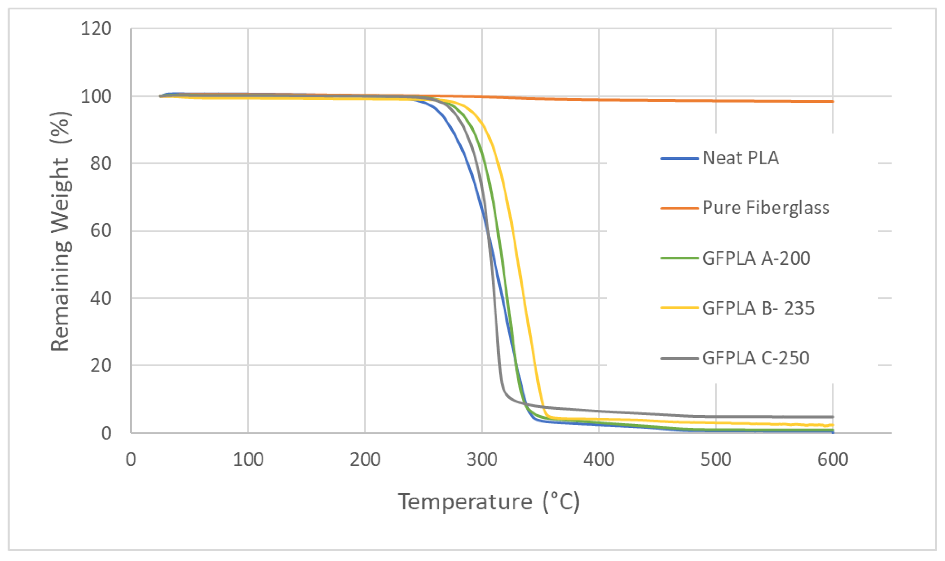
Table 3. Mass residue and standard deviation of six repetitive tests for PLA and GF-PLA composites A, B, and C.
SampleAverage Sample Mass (mg)Average Degradation Temperature (°C)Average Mass Residue (mg)Average Residue (%)/Fiberglass ContentRelative Standard Deviation (%)
PLA5.085284.580.000--
GF-PLA A7.824302.900.081.017111.0
GF-PLA B9.022319.390.222.38954.6
GF-PLA C7.746297.120.374.98828.6
Disclaimer/Publisher’s Note: The statements, opinions and data contained in all publications are solely those of the individual author(s) and contributor(s) and not of MDPI and/or the editor(s). MDPI and/or the editor(s) disclaim responsibility for any injury to people or property resulting from any ideas, methods, instructions or products referred to in the content.

